Article

Theoretical and Numerical Investigation of Reduction of Viscous Friction in Circular and Non-Circular Journal Bearings Using Active Lubrication

Department of Mechatronics, Mechanics and Robotics, Orel State University, 302015 Orel, Russia
*
Author to whom correspondence should be addressed.
Lubricants 2023, 11(5), 218; https://doi.org/10.3390/lubricants11050218
Submission received: 7 April 2023 / Revised: 9 May 2023 / Accepted: 11 May 2023 / Published: 13 May 2023
(This article belongs to the Special Issue Tribology Problems in Rotating Machinery)

Abstract

:
Reducing friction losses is one of the most common ways to improve fluid film bearings, whose adjustable design provides additional opportunities to improve their dynamic and tribological properties. Previous studies have shown the possibility of reducing viscous friction in actively lubricated bearings by adjusting the rotor position. This work provides a theoretical justification for the mechanism of this effect for the cases of purely laminar lubricant flows in journal bearings. The operating modes connected with the transition to turbulent phenomena and the occurrence of Taylor vortices are beyond the scope of this paper. Conditions that ensure the minimization of friction losses in hydrodynamic and hybrid bearings with hydrostatic parts are determined based on the equations describing viscous friction in a fluid film. In non-adjustable plain hydrodynamic bearings, the minimum of friction is achieved with the centered shaft position that is actually unstable due to the resulting forces configuration. In actively lubricated hybrid bearings, a further reduction in viscous friction is possible by combining film thickness and pressure distributions. Recombining them, along with adjustment of the shaft position, allows the optimization of the distribution of shear stresses in the fluid film. As a result, the shear stresses caused by the rotation of the shaft can be partially compensated by the stresses caused by the pressure gradient, reducing the torque-resisting rotation. In addition, additional benefits can be obtained in the minimum friction state by the reduced lubricant flow and power losses to its pumping. A series of numerical calculations for elliptical, 3-, and 4-lobe bearings show that non-circular bores provide additional variability in film thickness distribution and a premise for optimizing the bearing tribological parameters. Four-lobe bearing demonstrated the best ability for reducing viscous friction among the considered designs. The results obtained can be used as a basis for further optimization of the geometry of fluid film bearings of both active and passive designs by reducing power losses due to viscous friction.

Graphical Abstract

1. Introduction

Although fluid film bearings provide a relatively low friction coefficient in hydrodynamic lubrication mode, the total energy costs to overcome viscous friction can be significant, especially in some high-speed and/or powerful machines [1]. Reduction of friction in fluid film bearings also provides a reduction in heat generation, in the lubricant degradation rate, an increase in the minimum film thickness, and in the overall reliability of the machine. Papers [2,3] provide an overview of the most common and advanced ways to reduce friction in sliding bearings. The problem is most relevant for vehicle engines [4,5], power-generating machines [1,6], and a number of other applications.
Improving the lubricants’ properties is one of the most obvious ways to reduce friction in fluid film bearings. The most common ways are including additives in oils [7] and using less viscous liquids for lubrication [8].
A number of known methods for reducing friction assume improving the bearing geometry at different spatial scales. Considering the micro- and meso-levels, good results, such as reducing friction by tens of percentage, are obtained by texturing the bearing and/or rotor surfaces [9,10]. A review of such methods is presented, for example, in [11].
Regarding the macro-level, friction in bearings is reduced, for example, by introducing deformable regions [12] and optimizing the design and geometry of the unit as a whole [13]. An overview of actual and prospective design solutions for reducing friction in hydrostatic bearings, for example, is given in the already-mentioned paper [1].
The development of adjustable bearings gives additional potential to improve their tribological parameters, although, at the moment, friction is still quite rarely considered a controlled parameter in such systems. In [14,15], friction is considered an adjustable parameter for the general case of flat shear-pressure flows. Paper [16] describes a reduction in friction in linear sliding bearings by applying vibration actuators. In [17], viscous friction in a fluid film bearing is considered a parameter influenced by other adjustable parameters, in particular, by the lubricant supply pressure. However, the approaches to reducing friction in passive and active bearings are not limited to this.
This work is based on our previous research on actively lubricated journal bearings. In [18], the presence of minimum viscous friction was found numerically for the first time during the investigation of the bearing controller in connection with the adjustable shaft position in the bearing. Paper [19] considered the friction control in an actively lubricated journal and thrust bearings together with the control of the rotor position in more detail. A classification of the mechanisms for the formation and reduction of viscous friction was given. In [20], an initial experimental confirmation of the effect was given to justify the choice of setpoints for active fluid film bearings.
The present study develops the issue and proposes an in-depth and extended look at the effect of friction reduction in actively lubricated journal fluid film bearings. The theoretical analysis shows in more detail the mechanisms of reducing viscous friction when adjusting the shaft position in them. The numerical calculations illustrate the application of this approach to both circular and non-circular fixed geometry bearings. The obtained results and the conclusions made relate to the operating regimes of bearings with laminar lubricant flow. The states associated with the transition to turbulent flow, including the occurrence of Taylor vortices and the corresponding increase in torque required to rotate the shaft [21], are beyond the scope of this work. The results can be used to further optimize the design of fluid film bearings to provide reduced losses due to viscous friction. An additional advantage of the considered approach is that it can be combined with most of the other friction reduction methods mentioned above.

2. Materials & Methods

2.1. Subject Description

A fixed geometry hybrid journal bearing with active lubrication is considered the main subject in this paper. A part of the load capacity in it is created by the hydrodynamic effect. A controllable force impact on the rotor is created by the hydrostatic effect due to the lubricant supplied under pressure through the injectors. Point injectors (inlet orifices) are used for relatively light rotors, while heavier ones can be replaced by rectangular hydrostatic pockets. The pocket size should be small enough to keep the hydrodynamic effect significant. Active lubrication implies separate regulation of the lubricant supply pressure in each supply channel. A scheme and a photo of an experimental sample of the actively lubricated hybrid bearing (ALHB) are shown in Figure 1. Unlike ALHB, a conventional passive hybrid bearing (PHB) includes a common collector for all injectors so that the inlet lubricant pressure is equal in each of them.
The AHLB model is based on the numerical solution of the two-dimensional Reynolds equation:
x h 3 p x + z h 3 p z = 12 μ V + 6 μ U h x .
In addition to the basic assumptions required to apply Reynolds Equation (1), a number of additional assumptions have been introduced to focus on the physical basics of the viscous friction reduction effect. The problem was considered isothermal, also excluding taking into account the rotor misalignments, cavitation, and two-phase flows. The parameters of a basic circular hybrid journal bearing considered in this work are shown in Table 1.
The lubricant flow in the bearing in this work was considered laminar. The maximum Reynolds number of the considered bearing at 3000 rpm is Re = 630. The critical Reynolds number Rec for thin film flows is usually estimated at 2000–2300 [22,23,24]; however, Taylor vortices can start occurring in journal bearing at lower Reynolds numbers, in a range of 400–900 according to some experimental data [21], or theoretically more specifically, at Re = 580 [25]. According to this, most of the range of the operating conditions considered in this work, namely n = 0–3000 rpm, belongs to the purely laminar lubricant flow regime.
The externally pressurized lubricant supply through the hydrostatic injectors was taken into account during the numerical solution of Equation (1) as boundary conditions. The decrease in pressure as a result of throttling in the injectors and the bearing gaps was taken into account by joint solving the flow balance equation:
Q H = Q x + Q z + Q y = π d H 4 128 l H p 0 p H ρ K H μ .
KH is a coefficient for taking into account the flow turbulence in injectors:
K H = R e H R e * 3 4 .
ReH in (3) is the Reynolds number characterizing the lubricant flow in an injector; the limit Reynolds number is Re* = 2300.
The basic equation describing the film thickness in a circular bearing is:
h α = h 0 X sin ( α ) Y cos ( α ) .
For modeling the gap shape in non-circular bearings, the offsets C2, C3, and C4 were used for elliptical, 3-, and 4-lobe bores correspondingly for defining the fixed lobes geometry [26,27].
In simulation model Reynolds Equation (1) was solved together with Equations (2)–(4) numerically using the conventional finite differences method, using the ambient pressure at the ends of the bearing and the adjustable pressures in the lubricant supply channels as the boundary conditions.
A relatively simple proportional control law was used to adjust the lubricant pressure in the supply channels separately at each control axis, X and Y:
p 0 = K S V U 0 ± K P ε .
In Equation (5), KSV is a servo valve transfer ratio, U0 is a basic control signal level corresponding to the PHB state, KP is the proportional gain, and ε is the control error, i.e., the deviation of the rotor position from the setpoint. The variable sign in the degree means that in order to create some control action along the considered coordinate axis, the servo valve increases the pressure in one of the supply channels relative to the initial level provided by U0, while another servo valve decreases it in the opposite channel. The control system and the control process in an ALHB are described in more detail in [19].
Only a perfectly balanced and aligned rigid symmetric rotor was considered in the numerical procedures in this work, so the load applied to bearings is provided by its weight of 30 N in total. Its single-mass model was implemented by numerical solution of Lagrange equations used for the calculation of its motion in bearings, also as in [19].
The described simulation model has been tested in [19,20] by comparing it with different experimental results and showed good agreement both in the calculation of pressure distribution in bearings and in rotor motion calculation.

2.2. Initial Numerical and Experimental Background

Initially, the relationship between the magnitude of viscous friction and the rotor position in an ALHB was found during a numerical study of its controller in [18]. Due to the presence of a pronounced friction minimum in the calculation results, experimental studies were additionally carried out to confirm the effect. The appearance and structure of the experimental rig are shown in Figure 2.
A torque sensor between the motor and the rotor was used to measure the friction torque from hybrid bearings resisting the shaft rotation. The tested ALHB is located at the free end of the rotor, while the motor end bearing is a PHB. The lubricant supply pressure is controlled with servo valves. The rotor position is measured using displacement sensors.
The experiment carried out partially reproduced the numerical calculation in [18] and showed the dependence of the friction torque on the rotor position in the ALHB. The results of the experiment were partially presented in [20] and used as the basis for choosing the ALHB controllers’ setpoints. The comparison of the numerical and experimental results in a more visual and convenient form for analysis is shown in Figure 3.
The obtained results generally confirm the presence of a friction minimum at a more centered position of the rotor. However, there were some shortcomings in the design of the experimental rig; namely, it did not allow measuring the friction torque separately in the ALHB, and the measured torque values were close to the sensor’s lower measurement limit. The results did not allow us to fully evaluate certain aspects of the considered effect, such as the location of the supposed minimum friction point at a certain distance from the ALHB center, as well as the absolute values and range of change of the friction torque. Nevertheless, the general nature of the obtained results provides grounds to carry out a theoretical investigation of the effect of reducing viscous friction in ALHB when adjusting the rotor position compared to PHBs. Theoretical provisions and additional numerical results in this work are aimed to become the basis for an improved experimental study and understanding of the nature of the tribological behavior of adjustable rotor-bearing systems with various types of bearings. Section 3 presents a theoretical analysis of the mechanisms of the formation of viscous friction in fluid film bearings of various designs, followed by a number of numerical results for circular and non-circular bearings and their further discussion.

3. Results and Discussion

3.1. Theoretical Substantiation of the Minimum of Fluid Friction in Journal Fluid Film Bearings

The main equation for calculation of the torque created by the viscous friction forces in the lubricant film of a journal bearing is as follows:
T v f = R S h 2 p x + U μ h d S = S R h 2 p x d S + S R U μ h d S = T v f Pr + T v f Rot .
Equation (6) is derived using Newton’s equation of viscosity [28,29] and describes the viscous friction torque caused by the viscous stresses in the thin film lubricant flow within the bearing gap with a rotating shaft. As noted in Section 2.1, the lubricant flow under the given conditions is considered laminar, so the influence of turbulence is excluded from consideration. The first component of (6) T v f Pr shows the contribution of the stresses caused pressure drops within the fluid film, while the second part T v f Rot describes the contribution of the stresses caused by the partial entrainment of the lubricant film by the shaft surface moving along the bearing walls. The resulting viscous friction torque Tvf resists the shaft rotation in the bearing at the considered conditions.
The active lubrication system in the ALHB affects both directly the pressure distribution and, indirectly, the rotor position. The rotor displacements lead to a change in the gap function h and, as a result, to a change in the hydrodynamic pressure distribution, which is described by Reynolds Equation (1).
An analysis of the conditions providing minimization of the viscous friction forces (6) in fluid film bearings will be presented below.

3.1.1. Plain Hydrodynamic Bearings

A plain hydrodynamic bearing is the basic system for a hybrid bearing. The active lubrication system can be considered a superstructure that influences the pressure distribution in the fluid film and the rotor position in the bearing.
If the shaft takes a steady position in the hydrodynamic bearing, then according to Equation (6) and under the assumptions made, the pressure distribution depends on the lubricant viscosity µ, the shaft rotation speed U and its position in bearing h. The first two parameters are considered constant since they are set by the design and operating conditions of the machine. The shaft position in the bearing is described by the gap function (4). Thus, the equilibrium position of the shaft heq = f(U,µ,h0) is one of the design characteristics of a plain bearing along with the minimum film thickness, hminheq. In this case, the condition for the minimum of Tvf can be formulated if the parameter h is considered variable. The shaft can change position relative to the equilibrium in a plain bearing under disturbing and/or control forces, for example, as in [30]. In this case, the right part of Equation (6) T v f Rot will be a constant for given U and µ at a constant bearing clearance geometry:
S R U μ h d S = const .
Thus, the condition for minimizing Tvf can be formulated as
h 2 p x min .
The ultimate case of condition (8) is the uniform pressure distribution in the entire bearing. Taking into account Equation (7), in a circular plain bearing, this is ensured by the centered position of the rotating shaft when the film thickness is constant over the entire circumference, h = h0. With that, in non-circular bearings, the centered shaft position is not associated with constant clearance.
In the general case, the most centered position of the rotor can be called the condition for minimizing viscous friction in a plain hydrodynamic bearing. In practice, this configuration is of little use since the bearing forces and the load capacity are minimal with a centered shaft position. The close-to-center shaft position can be achieved either at high rotational speeds and/or lubricant viscosity, as an instantaneous (non-equilibrium) position, or under external control, as in [30]. In this case, the rotor motion may be unstable in the absence of restraining forces, and the bearing turns into a damper or a safety device in the machine.

3.1.2. Hydrostatic and Hybrid Bearings

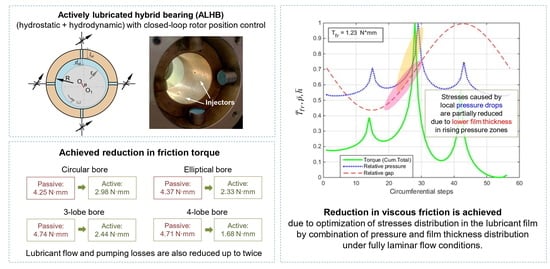
Unlike a hydrodynamic bearing, hydrostatic, and hybrid (combination of hydrostatic and hydrodynamic) bearings, the hydrostatic forces provide a stabilizing effect even with the centered shaft. Four lubricant supply channels create four pressure peaks evenly distributed around the circumference in the considered hybrid bearing design, as shown in Figure 4. Injectors create local zones with modified pressure regulated with the control system and servo valves. The pressure ratio and throttling effect determine the equilibrium position of a balanced rotor in the bearing.
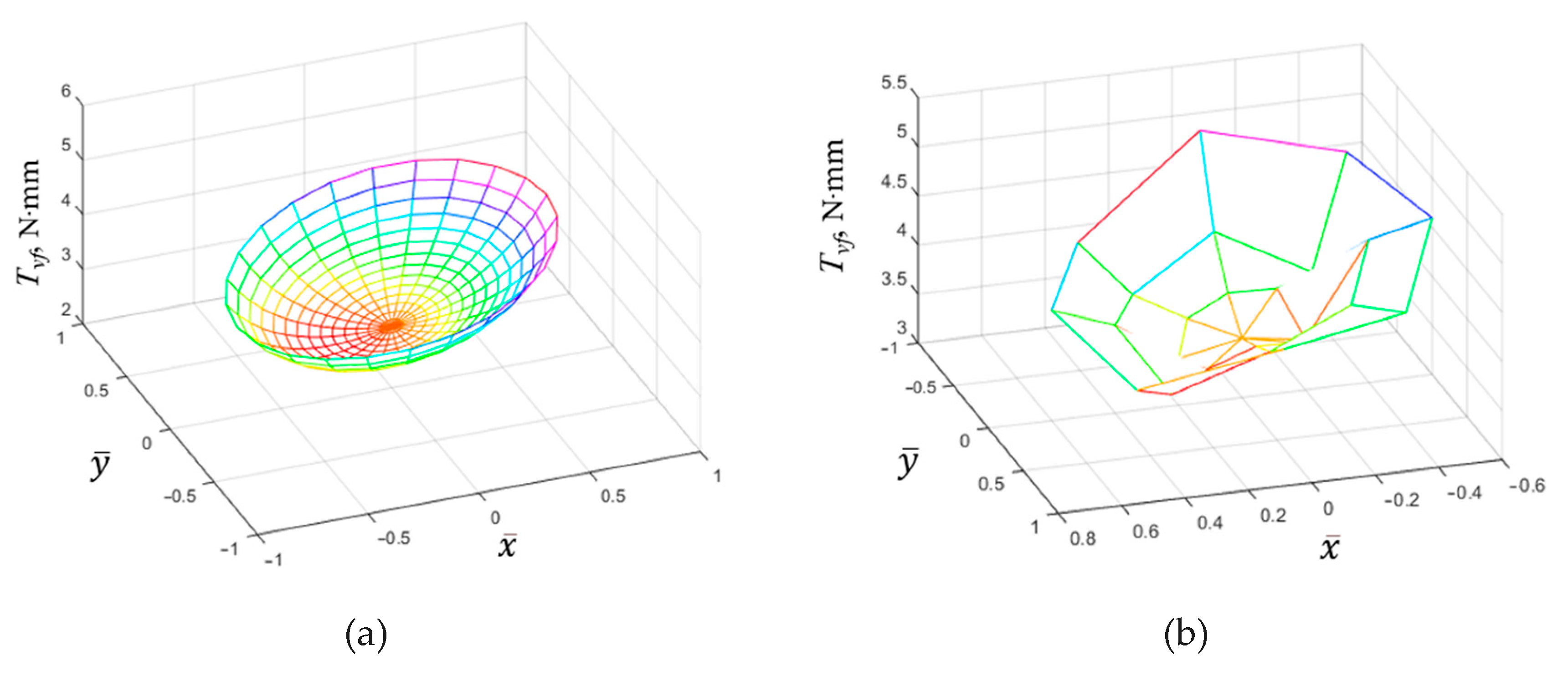
A change in the pressure and film thickness distribution compared to a plain bearing also provides a change in the distribution of shear stresses in the fluid film and hence the viscous friction torque. In particular, Figure 4a shows the pressure distribution in a conventional passive hybrid bearing (PHB), and Figure 4b shows the pressure distribution in an ALHB holding the shaft in the minimum friction according to [18]. This effect will be analyzed in more detail below.
The contribution of the right part of (1) T v f Rot to the total viscous friction in a hybrid bearing remains the same as for a hydrodynamic bearing. On the contrary, due to the presence of multiple pressure drop zones in the central region of the hybrid bearing, the structure of the shear stresses resulting in viscous friction differs from plain bearing. The differences are primarily provided by the left side of (1) T v f Pr . A number of states of a rotary system with the hybrid bearing were calculated to evaluate its tribological behavior:
(1)
centered equilibrium shaft position, provided by operation of the ALHB control system;
(2)
centered non-equilibrium shaft position in the PHB;
(3)
equilibrium shaft position with minimal friction, provided by the operation of the ALHB control system, as in the case in Figure 4b;
(4)
non-equilibrium shaft position at the same point as in the previous case (item 3), but in the PHB;
(5)
equilibrium natural shaft position in the PHB, as in the case in Figure 4a.
The calculation results are presented in 
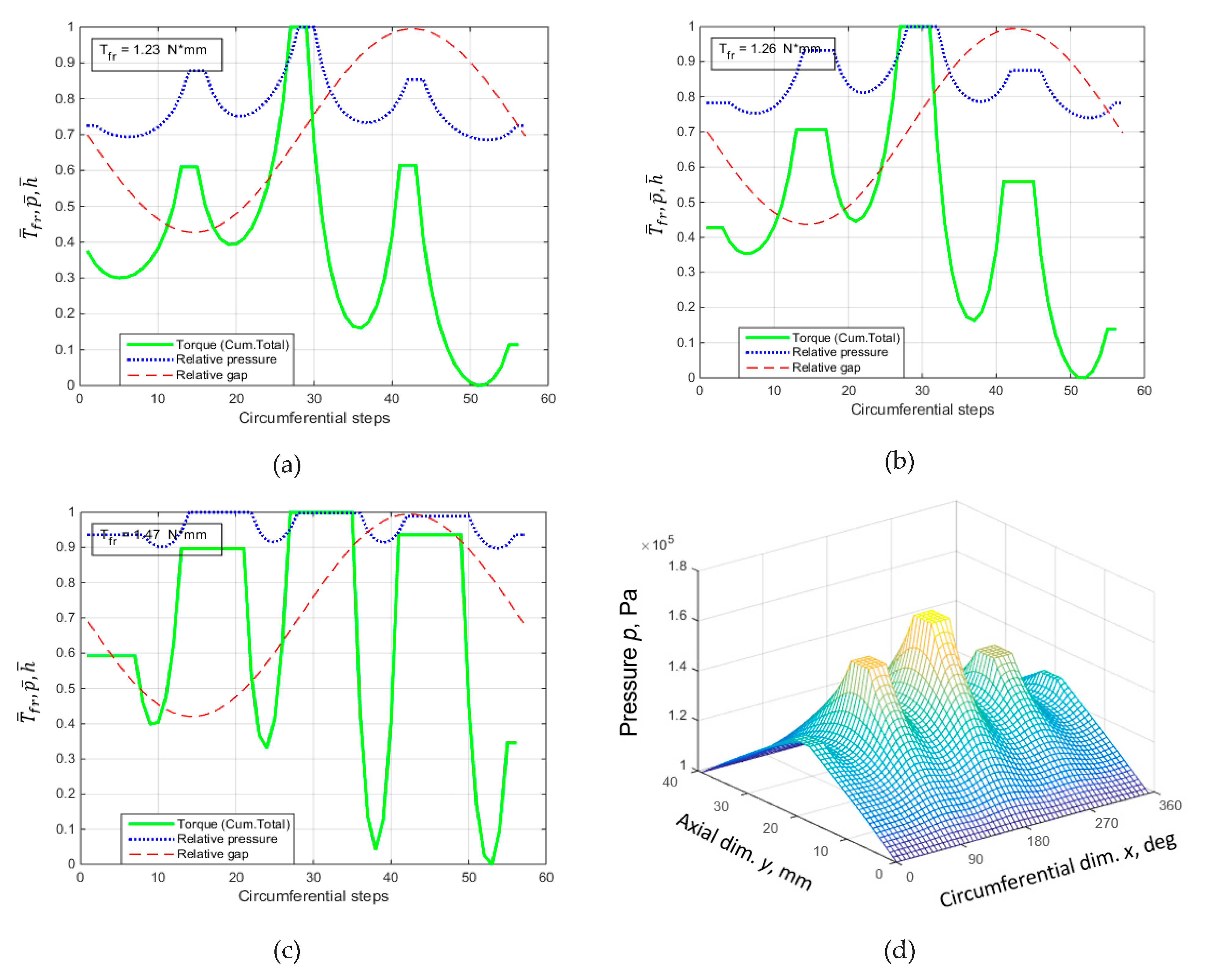
Figure 5 in the corresponding order, adding the diagram illustrating the shaft positions in the bearing for these cases. The rotation speed of a perfectly balanced rotor in all cases was 750 rpm. With it, the contribution of the hydrodynamic effect to the bearing pressure distribution is relatively small, and the effect of the hydrostatic component can be considered in a more isolated manner.
The pressure and film thickness distributions in Figure 5 are presented in a dimensionless form, respectively, p ¯ = p / p m a x and h ¯ = h / h 0 . Pressure distribution p = pcl is given for the central cross-section of the bearing passing through the centers of the injectors. This distribution characterizes the tribological state of the bearing quite fully due to its symmetry and the absence of misalignments. The friction torque Tvf is presented as the cumulative total of the integral in (1) for the same pressure distribution pcl at the bearing center line. The resulting graph shows, in fact, the change in the integral sum of the moments of shear-pressure stresses in the central zone of the bearing when integration in the direction of the bearing z-axis is excluded from (1):
T v f = R 2 π R h 2 p c l x + U μ h d x .
A joint analysis of the T ¯ f r , p ¯ ,   a n d   h ¯ graphs in Figure 5 with Equation (9) clarifies the contribution of shear-pressure stresses in different zones of the fluid film in the circumferential direction to the total viscous friction Tvf for the various system states.
Figure 5a,b demonstrates that, like in a plain bearing, the resulting friction decreases at the centered shaft position in comparison with its natural position, Figure 5e. Indeed, in this case:
2 π R h 2 p x d x = h 0 2 2 π R p x d x = 0 ,
because in a circular bearing h = h0 = const. Additionally, since the pressure distribution is closed in the circumferential direction, and considering the assumptions made:
2 π R p x d x = 0 .
However, for any non-centered shaft positions in a circular bearing h ≠ const. The changing film thickness corrects Equation (10) so that:
2 π R h 2 p x d x 0 .
Indeed, Figure 5a,b represent the centered shaft position. In the (b) case, it is a non-equilibrium state, while in the (a) case, it is equilibrium provided by an active lubrication system, which affects the pressure distribution. Since the film thickness is constant in the whole bearing gap, a change in the pressure distribution does not lead to a change in the friction torque. The stresses in the fluid film caused by the pressure gradient cancel each other out. The friction torque value Tvf = 1.46 N∙mm in this case, calculated numerically according to (1), is equal to the minimum possible torque for a plain hydrodynamic bearing, provided only by the shear stresses in the Couette flow.
Further analysis of Figure 5 shows that for some system states, the combination of clearance and pressure functions is such that the total viscous friction torque can become even smaller than in the case of the mentioned centered shaft position. Figure 5c,d shows the states with the shaft at the calculated friction minimum position at 750 rpm. In case (c), like in case (b), the system state is equilibrium, provided by an active lubrication system, and in case (d), it is non-equilibrium, for the case of the PHB. While the film thickness distribution is equal in cases (c) and (d), the difference is in the pressure distribution. In case (c), in the ALHB, the largest pressure changes occur in the divergent part of the bearing gap. The zone of the greatest increase in pressure falls on the region with a smaller gap than the almost symmetrical zone of the greatest pressure fall. The stresses caused by the pressure gradient in the area of increasing pressure around the injector make a smaller contribution to the total viscous friction torque due to the thinner fluid film. In Figure 5c, this can be seen in the drop in the T ¯ f r value after this region in comparison to the (d) case in the PHB, where such a drop is not observed due to a more uniform pressure distribution. As a result, the total friction torque in the PHB is 1.88 N∙mm, which is 29% greater than at the centered shaft position and 53% greater than at the same shaft position in the ALHB.
Another effect seen in Figure 5 is the reduction in lubricant flow through the bearing when the shaft is in the minimum friction or centered position. For the considered case, the water flow rate changes approximately two times, from 4 to 2 L/min. This is primarily due to a change in the lubricant pressure in the supply channels and its relationship with local hydraulic resistances in the bearing gap near the injectors. In particular, to raise the rotor above the initial “natural” position, the control system increases the pressure in the lower channel and lowers it in the opposite upper one. The supply pressure to the channels along the X-axis partially changes. Further, due to the displacement of the shaft in the bearing, the clearance decreases, and the local hydraulic resistance increases in the area of those injectors through which the greatest consumption of lubricant occurs in the PHB. As a result, the total lubricant consumption is reduced, and hence the required power for its pumping, which will be further discussed below.
The shear stresses in the fluid film caused by the shaft rotation at the minimum friction position in the ALHB are partially offset by the stresses caused by the pressure gradient. Thus, the total viscous friction torque in the ALHB is lower than the theoretical minimum in a similar hydrodynamic plain and in a PHB. In addition, the theoretical minimum of friction is practically unattainable in plain hydrodynamic bearings due to the minimization of the load capacity at the centered shaft position of the rotor. At the same time, an ALHB is able to provide an equilibrium shaft position at the theoretical minimum friction region and maintain this state for the required time.
Another effect seen in Figure 5 is the reduction in the lubricant flow through the bearing when the shaft is at the minimum friction position or at the centered position. The water flow rate is approximately halved, from 4 to 2 L/min for the considered case. This is primarily due to the controllable change in the lubricant pressure in the supply channels and its relationship with local hydraulic resistances in the bearing gap near the injectors. In particular, the ALHB control system increases the pressure in the lower channel and decreases it in the opposite upper one in order to move the shaft above the initial natural position, typical for a PHB. The supply pressures to the channels along the X-axis are also partially adjusted. Due to the shaft displacement, the clearance decreases, and the local hydraulic resistance increases near the injectors that provide the greatest lubricant flow in the PHB. As a result, the total lubricant flow, and hence the power required for pumping it, is reduced, which will be further discussed below.

3.2. Minimization of Viscous Friction in Non-Circular ALHB

The conclusions of Section 3.1 are related primarily to circular fluid film bearings. The eccentric shaft position in them is characterized by the presence of only convergent and divergent regions. However, in practice, non-circular bearings with various types of bores are used. They improve the stability of the rotor motion with a certain decrease in load capacity and an increase in viscous friction [31]. With a non-circular profile, two or more convergent and divergent areas may appear in the bearing. The implementation of the active lubrication principle in them makes it possible to obtain more diverse ratios of pressure and film thickness than in circular bearings. This gives more opportunities for further optimization of the viscous friction parameters.
A number of friction-versus-shaft-position diagrams were obtained for actively lubricated elliptical, 3- and 4-lobe bearings. As in circular bearings, the active lubrication is implemented in them with four evenly spaced injectors. Although different local hydraulic resistances are possible for different injectors in non-circular bearings, the simulation shows that this has little effect on the quality of rotor position control. Adopting the control techniques to the gap shape is not quite necessary, although it could be one of the possible directions for optimizing active rotor-bearing systems.
Figure 6 shows the calculation results for the considered non-circular bearings. The elliptical bore is characterized by the parameter ER = C2/h0, the 3-lobe by LR = C3/h0, and the 4-lobe by WR = C4/h0. The C2, C3, and C4 values are the offsets of the boring radii relative to the radius of the circular bearing R. For a more complete analysis, several versions of each non-circular bearing with more and less pronounced geometric changes were additionally tested. The simulation was performed for three rotation speeds of 750, 1500, and 3000 rpm. The minimum speed of 750 rpm is set to be high enough to provide the rotor lift-off in the water-lubricated hydrodynamic bearing. The maximum speed of 3000 rpm was chosen because, under the conditions considered, the minimum friction position at this speed was situated quite close to the bearing center.
A summary of the friction parameters and minimum film thickness of the tested bearings is presented in Table 2. It shows the results for the rotation speed of 1500 rpm, as this is the most representative mode. Data for other speeds are presented in Appendix A, Table A1 and Table A2.
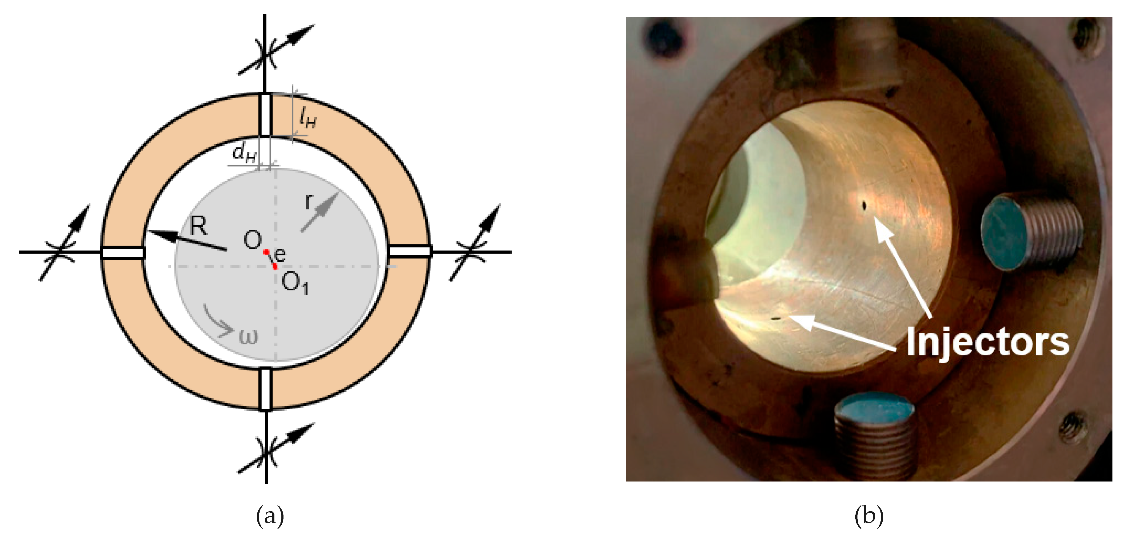
Figure 6 shows that the diagrams of the dependence of friction on the shaft position in the ALHB have the same pronounced friction minima for all considered types of non-circular bearings as for circular ones. In addition, one can note their characteristic shape with local zones of increased friction at higher eccentricities. The number of such zones coincides with the number of constituent elements of the bearing profile. This is due to a local decrease in the gap when the rotor in the ALHB is positioned near the protruding profile elements. In all cases, the position with minimum friction is located near the x-axis and tends to move towards the bearing center with increasing rotation speed. In all cases, the minimum friction points for speeds of 750, 1500, and 3000 rpm are farther apart for non-circular bearings and also for more pronounced non-circularity.
The calculations show, as expected, that the load capacity of the bearings with a more pronounced non-circular profile tends to decrease. This is manifested in a decrease in the minimum film thickness hmin. The viscous friction torque at the natural shaft position in the PHB also tends to be higher than in a circular bearing due to the increase in pressure gradient zones.
As in circular bearings, the implementation of rotor position control using active lubrication in non-circular cases allows the reduction of viscous friction relative to the corresponding PHBs. At the same time, non-circular bearings demonstrate the ability to achieve an even greater reduction in friction. Thus, according to the data in Table 2, a reduction in viscous friction of up to 30% was achieved for the circular bearing. For non-circular ones with comparable initial friction, the active lubrication reduced it by up to 47% for elliptical (ER = 0.4), 49% for 3-lobe (LR = 0.5), and 74% for 4-lobe (WR = 0.5) bores. At the same time, if the friction in the PHB increases for more pronounced non-circularities, the ability of ALHB to reduce it increases in such cases. Therefore, the greatest achieved reduction in friction was 53% for elliptical and 3-lobe bearings and 83% for the 4-lobe design. The latter result thus shows a friction reduction of almost six times compared to the PHB. This result stands out against the background of other bearings and, possibly, can be associated with simplifications in modeling the geometry of fixed wedges, for example, in the omission of the rounding of their trailing edges. However, despite the possible computational inaccuracies, the result is consistent with the general trend when the non-circular bearings provide additional opportunities in optimizing the tribological state behavior when using active lubrication.
In addition, a number of diagrams similar to those shown in Figure 5 were calculated for non-circular bearings to further illustrate the phenomena. The diagrams are presented in Appendix B and show data for each of the considered types of bearings at 1500 rpm in the configurations that provide the greatest reduction in friction.

3.3. Discussion

The obtained results demonstrate how active lubrication in hybrid fluid film bearings can not only improve the parameters of rotor motion but also optimize their tribological behavior. It allows the rotor-bearing system to achieve such states that the resulting viscous friction torque can become significantly lower than its minimum possible value for similar plain bearings without external pressurizing. The key factor for this is the relation between the film thickness and pressure distributions that determine the stresses caused by the pressure gradient in the lubricant film. The viscous friction forces in the bearing can be reduced by optimizing the stress distribution through active lubrication. This technique allows influencing the pressure distribution both in direct and indirect ways through adjusting the lubricant pressure in supply channels and the shaft position, correspondingly. As a result, more variations of film thickness and pressure distributions can be obtained in the ALHB compared to the passive plain bearing and PHB.
In the general case, the minimization of viscous friction, in this case, is provided by the coincidence of the zones of the largest pressure drops with the divergent area or areas of the fluid film. Using this provision as a criterion during calculations provides more opportunities for optimizing the tribological behavior of various fluid film bearings. Being based on fundamental physical principles, this approach is likely to be applicable not only to actively lubricated bearings but also to active bearings utilizing other control principles, an overview of which is given, for example, in [32]. However, a detailed analysis of the possibility of reducing viscous friction due to the considered approach is required for each new control scheme.
It should be noted here that this work provides a basic theoretical justification for the considered effect and characterizes the main possibilities of the approach to reducing viscous friction. It is based on a number of mentioned simplifications and assumptions that should be taken into account when evaluating the results for practical implementation. Numerous studies show that such factors as rotor misalignment, turbulence, and multi-phase flows in the fluid film can have a significant impact on the bearing characteristics. In particular, they can significantly modify the pressure distribution and even the continuity of the lubricant film, especially in the divergent part of the bearing gap, which can significantly affect the considered phenomena of reducing viscous friction. On the other hand, the externally pressurized lubricant supply to the appropriate areas of the fluid film can possibly reduce the likelihood of the effects associated with its discontinuities. The influence of these factors on the implementation of the described principle of reducing viscous friction requires additional studies, also taking into account the design features and the operating modes of certain rotor-bearing systems.
The influence of turbulence in this issue is particularly important in the context of this study. The transition from fully laminar to turbulent lubricant flow in the bearing, including the initial occurrence of Taylor vortices with an increasing Reynolds number, increases the resistance of the fluid film to the rotation of the shaft [21]. These phenomena qualitatively change the tribological behavior of the rotor-bearing system and limit the applicability of the presented results to purely laminar operating modes of bearings. The issue of the influence of Taylor vortices and fully turbulent lubricant flow on the implementation of the considered approach requires additional research, including extending the mathematical and numerical simulation models. Additionally, while considering implementing the described approach in a certain application, other factors that bring the transition to turbulent regimes closer should be considered, such as thermal effects.
Further, a bearing with a relatively high h0/R ratio of 0.005 was simulated during the numerical procedures because it corresponds to the actual parameters of the experimental bearing considered in [19]. At the same time, the scope of this work includes only the phenomena in thin lubricant films, which are usually considered in the study of conventional fluid film bearings. In such films, the inertia forces in the lubricant flow are small compared to the viscous forces, and Reynolds Equation (1) is applicable. Since the considered ratio h0/R ratio of 0.005 puts the considered system relatively close to the corresponding limits, additional numerical tests were carried out to verify the validity of the obtained results for more conventional journal bearings. The tests have shown that for circular bearings with thinner films, the ratios of tribological parameters remain the same, as shown in this paper. In particular, in a circular ALHB with h0/R = 0.002 at 1500 rpm, the maximum reduction in friction relative to the same PHB at the same Sommerfeld number is 29% (from 10.80 to 7.68 N·mm), which coincides with the data in Table 2 for the tested bearing with h0/R = 0.005. Thus, in accordance with the principle of similarity, the results shown and the conclusions made can be considered valid for bearings in which inertia forces in the fluid film can be neglected according to their design and operation parameters [33].
Another interesting conclusion is that the reduction of viscous friction in the fluid film of hybrid bearings is not the only benefit of the implementation of the considered approach in terms of reducing energy costs. As the results show, a reduction in lubricant flow can lead to even more effect in energy saving in absolute terms than the reduction in the bearing friction torque. For the results in Figure 5, the viscous friction torque was reduced a maximum of 2.3 times in the ALHB compared to the PHB, and the lubricant flow was also reduced almost two times. The power losses for overcoming the viscous friction Nvf and for lubricant pumping through the bearing Np are:
N v f = T v f ω ;
N p = Q H p 0 .
In absolute terms, the corresponding power losses in the considered case were reduced from 2.2 to 1 W for Nvf, and from 27 to 14.5 W for Np in a single bearing. So, the expected energy savings due to the reduction in the lubricant flow is 10 times more than due to the reduction in the viscous friction. With that, the last can also provide some indirect additional advantages, like improvement in the dynamic rotor behavior under reduced friction, the possibility of refusing from the lubricant cooling facilities, etc. It also should be noted that the power losses in the lubricant supply pipelines are not considered, excluding the impedance in the bearing’s injectors required for the calculation of the hydrostatic effect. Such power losses depend on a specific configuration of the supply system and usually are subject to optimization.
Most of the associated energy costs for the ALHB control system operation are accounted for by computing facilities, the operation of sensors, and servo valves. The energy consumption of these elements can be tens of watts. However, when scaling the rotor system, the energy savings due to the implementation of the approach will increase, while the energy costs for the operation of the control system can remain almost unchanged. Thus, a brief analysis shows that the total energy balance can be positive starting from the scale of the considered rotor system, and with its increase, the gain can increase.
The final decision on implementing the approach in a certain application, both in general and in detail, should be based on a set of requirements and the operating conditions of the rotor machine. For example, the results indicate that a greater gain in reducing friction can be obtained for more heavily loaded machines with more eccentric initial rotor positions in bearings, i.e., characterized by a lower Sommerfeld number. However, as noted in Section 2.1, heavier rotors may require the use of rectangular hydrostatic pockets instead of the considered point injectors. The circumferential extent of the pockets affects the pressure and shears distribution in the fluid film and, correspondingly, the effect of viscous friction reduction. Results of numerical tests for ALHB with different pocket sizes are shown in Figure 7.
As Figure 7 shows, the circumferential size of hydrostatic pockets does not significantly affect the minimal achievable friction torque value to a certain extent. An increase in friction is observed when the total pocket area reaches approximately half of the bearing’s circumferential length. Thus, it is preferable to increase the pocket size in the axial direction to obtain more controlling hydrostatic force. Additionally, the zone with the greatest pressure drops around the lubricant supply points in the circumferential direction should remain significantly less than the size of the divergent gap zone in the corresponding direction.
Since the considered mechanism of viscous friction reduction is universal for all fluid film bearings from the point of view of its physics, further optimization of their design is reasonable in order to increase the effect. The considered example of a 4-lobe bearing shows that there is a perspective for optimizing the bore shape and the shape and location of the lubricant supply channels to further minimize friction. This problem may be quite challenging, so it can be solved, for example, by using the optimal design procedures [34,35]. In this case, a number of parameters, like the load capacity, lubricant consumption, as well as other integral and dynamic characteristics of rotor-bearing systems, can also be considered objective functions along with the friction.
Further investigation of the described approach requires more experimental results and numerical calculations, taking into account a number of factors omitted in the present work. First of all, it should be aimed to identify the realistic limitations on the practical use of the considered approach to the reduction of viscous friction in fluid film bearings.

4. Conclusions

This work studies the mechanism for reducing viscous friction in actively lubricated fluid film bearings from the point of view of fundamental physical dependencies. The possibility of such an approach was previously revealed in numerical studies and is partly confirmed by the experimental results. The key factor for the implementation of the considered effect is the optimization of the distribution of the stresses in the fluid film caused by the shaft rotation and the pressure drops. The effect was studied by analyzing the fundamental equations of hydrodynamics and jointly performing a series of numerical calculations. The results show that certain combinations of film thickness and pressure distributions are able to modify the stress distribution caused by the pressure gradient in such a way that the total friction torque resisting the shaft rotation in an actively lubricated hybrid bearing can be lower than the possible minimum of friction in a similar plain hydrodynamic bearing. The results obtained are valid for a fully laminar lubricant flow in the film before the occurrence of Taylor vortices and flow turbulence.
Non-circular bearings provide larger variability in film thickness that gives additional possibilities for optimizing their tribological parameters compared to circular ones. According to the numerical results obtained for elliptical, 3-, and 4-lobe fixed geometry actively lubricated bearings, the last one showed the best performance in reducing viscous friction. Calculations show the greatest decrease in viscous friction under ideal conditions for the 4-lobe bearing by almost six times, while a typical reduction ratio is two to three times for other tested bearings.
It was also found that commensurate in relative terms energy savings can be achieved when implementing the approach due to the concomitant reduction in lubricant flow through the bearing and, consequently, in the power for pumping it.
The presented theoretical explanation of the effect of reducing viscous friction by active lubrication gives a deeper look at the issue of designing high-end bearings and, in particular, the analysis and optimization of their tribological behavior. This applies to both adjustable and conventional passive fluid film bearings. In terms of adjustable bearings, viscous friction can be considered an adjustable parameter or, at least, taken into account during the development of controllers. For conventional passive bearings, the considered effect can be taken into account during formulation and solving optimal design problems.
At the same time, the issue requires further clarification through experimental and numerical studies, taking into account a larger number of factors to assess the perspectives and limitations of the actual application.

Author Contributions

Conceptualization, D.S.; Formal analysis, D.S.; Funding acquisition, D.S.; Investigation, D.S. and Y.K.; Methodology, D.S.; Project administration, D.S.; Resources, D.S.; Software, D.S. and Y.K.; Supervision, D.S.; Validation, D.S. and Y.K.; Visualization, D.S. and Y.K.; Writing—original draft, D.S. and Y.K.; Writing—review & editing, D.S. and Y.K. All authors have read and agreed to the published version of the manuscript.

Funding

The study was supported by the Russian Science Foundation grant No. 22-79-00289, https://rscf.ru/en/project/22-79-00289/, accessed on 10 May 2023.

Data Availability Statement

Not applicable.

Acknowledgments

The authors express their gratitude to the Russian Science Foundation for the provided financial support and to the reviewers for their contribution into improvement of the paper in several aspects.

Conflicts of Interest

The authors declare no conflict of interest.

Nomenclature

List of abbreviations
ALHBActively lubricated hybrid bearing
PHBPassive hybrid bearing
List of symbols
x, y, z, αCartesian and angle coordinates
X, YInstant coordinates of shaft center
V, UShaft radial and circumferential velocities
O, O1Center of bearing and shaft
hBearing radial clearance (function)
heqBearing radial clearance distribution at equilibrium state
h0, hminInitial and instant minimum film thickness
ρDensity of lubricant
µDynamic viscosity of lubricant
QH, Qx, Qy, QzLubricant flow rates
pPressure of lubricant (function)
pclPressure distribution along bearing centerline
p0, pmaxInstant and maximum lubricant supply pressure
TvfViscous friction torque in bearing
TPr, TRotParts of torque provided by pressure gradient and shaft rotation
Nvf, NpPower losses due to viscous friction and to lubricant pumping
n, ωRotation and angular shaft speed
r, dShaft radius and diameter
R, DBearing radius and diameter
LBearing length
SBearing surface area
ER, LR, WRNon-circularity (Ellipticity, Lobe and Wedge) rates
C2, C3, C4Offsets of non-circular bearings
R1, R2Radii of elliptical bearing
lH, dHInjector length and diameter
K, KHTurbulence coefficient in bearing and injectors
Re, ReHReynolds number in bearing and in injector
ReCCritical Reynolds number
KSVServo valve transfer ratio
KPControl system proportional gain
U0Basic control signal level
εControl error

Appendix A

Table A1. Parameters of the tested bearings at 750 rpm.
Bearing Typeh0, µmhmin, µm T v f P H B , N·mm T v f m i n , N·mm
Circular100602.821.23
EllipticalER = 0.2105772.401.00
ER = 0.4842.232.33
ER = 1872.040.68
3-LobeLR = 0.2105672.621.07
LR = 0.5682.552.44
LR = 1642.470.74
4-LobeWR = 0.2105652.511.18
WR = 0.5652.370.79
WR = 1582.400.50
Table A2. Parameters of the tested bearings at 3000 rpm.
Bearing Typeh0, µmhmin, µm T v f P H B , N·mm T v f m i n , N·mm
Circular1008010.026.17
EllipticalER = 0.2105848.905.36
ER = 0.4848.475.02
ER = 1837.824.49
3-LobeLR = 0.2105849.305.62
LR = 0.5848.995.31
LR = 1838.654.91
4-LobeWR = 0.2105828.846.27
WR = 0.5778.195.70
WR = 1677.965.35

Appendix B

Figure A1. Minimum friction states at 1500 rpm for non-circular ALHBs: (a) elliptical, ER = 1; (b) 3-lobe, LR = 1; (c) 4-lobe, WR = 1.
Lubricants 11 00218 g0a1aLubricants 11 00218 g0a1b

References

  1. Wasilczuk, M. Friction and Lubrication of Large Tilting-Pad Thrust Bearings. Lubricants 2015, 3, 164–180. [Google Scholar] [CrossRef]
  2. Shi, G.; Yu, X.; Meng, H.; Zhao, F.; Wang, J.; Jiao, J.; Jiang, H. Effect of surface modification on friction characteristics of sliding bearings: A review. Tribol. Int. 2023, 177, 107937. [Google Scholar] [CrossRef]
  3. Ligier, J.-L.; Noel, B. Friction Reduction and Reliability for Engines Bearings. Lubricants 2015, 3, 569–596. [Google Scholar] [CrossRef]
  4. Razavykia, A.; Delprete, C.; Baldissera, P. Numerical Study of Power Loss and Lubrication of Connecting Rod Big-End. Lubricants 2019, 7, 47. [Google Scholar] [CrossRef]
  5. Summer, F.; Grün, F.; Offenbecher, M.; Taylor, S. Challenges of friction reduction of engine plain bearings–Tackling the problem with novel bearing materials. Tribol. Int. 2018, 131, 238–250. [Google Scholar] [CrossRef]
  6. Tiwari, G.; Kumar, J.; Prasad, V.; Patel, V.K. Utility of CFD in the design and performance analysis of hydraulic turbines—A review. Energy Rep. 2020, 6, 2410–2429. [Google Scholar] [CrossRef]
  7. Zhang, X.; Yan, Y.; Wang, P.; Zhang, T.; Liu, S.; Ye, Q.; Zhou, F. Thiadiazole functionalized covalent organic frameworks as oil-based lubricant additives for anti-friction and anti-wear. Tribol. Int. 2023, 183, 108393. [Google Scholar] [CrossRef]
  8. Knauder, C.; Allmaier, H.; Sander, D.E.; Salhofer, S.; Reich, F.M.; Sams, T. Analysis of the Journal Bearing Friction Losses in a Heavy-Duty Diesel Engine. Lubricants 2015, 3, 142–154. [Google Scholar] [CrossRef]
  9. Furukawa, K.; Ochiai, M.; Hashimoto, H.; Kotani, S. Bearing characteristic of journal bearing applied biomimetics. Tribol. Int. 2020, 150, 106345. [Google Scholar] [CrossRef]
  10. Vlădescu, S.-C.; Fowell, M.; Mattsson, L.; Reddyhoff, T. The effects of laser surface texture applied to internal combustion engine journal bearing shells—An experimental study. Tribol. Int. 2019, 134, 317–327. [Google Scholar] [CrossRef]
  11. Wang, Z.; Ye, R.; Xiang, J. The performance of textured surface in friction reducing: A review. Tribol. Int. 2023, 177, 108010. [Google Scholar] [CrossRef]
  12. Rasheed, H.E. The reduction of friction in axially non-cylindrical journal bearings using grooved bearing shells. Tribol. Ser. 1998, 34, 535–541. [Google Scholar] [CrossRef]
  13. Ding, A.; Ren, X.; Li, X.; Gu, C. Friction power analysis and improvement for a tilting-pad journal bearing considering air entrainment. Appl. Therm. Eng. 2018, 145, 763–771. [Google Scholar] [CrossRef]
  14. Schulmeister, J.C.; Dahl, J.M.; Weymouth, G.D.; Triantafyllou, M.S. Flow control with rotating cylinders. J. Fluid Mech. 2017, 825, 743–763. [Google Scholar] [CrossRef]
  15. Floryan, J.M.; Zandi, S. Reduction of pressure losses and increase of mixing in laminar flows through channels with long-wavelength vibrations. J. Fluid Mech. 2019, 864, 670–707. [Google Scholar] [CrossRef]
  16. Engel, T.; Lechler, A.; Verl, A. Sliding bearing with adjustable friction properties. CIRP Ann. 2016, 65, 353–356. [Google Scholar] [CrossRef]
  17. Mansoor, Y.; Shayler, P. The effect of oil feed pressure on the friction torque of plain bearings under light, steady loads. Tribol. Int. 2018, 119, 316–328. [Google Scholar] [CrossRef]
  18. Shutin, D.; Savin, L.; Polyakov, R. Influence of a Control System in an Active Journal Hybrid Bearing on the Energy Parameters of Its Operation. Int. J. Energy Environ. 2017, 11, 1–4. [Google Scholar]
  19. Li, S.; Zhou, C.; Savin, L.; Shutin, D.; Kornaev, A.; Polyakov, R.; Chen, Z. Theoretical and experimental study of motion suppression and friction reduction of rotor systems with active hybrid fluid-film bearings. Mech. Syst. Signal Process. 2023, 182, 109548. [Google Scholar] [CrossRef]
  20. Li, S.; Babin, A.; Shutin, D.; Kazakov, Y.; Liu, Y.; Chen, Z.; Savin, L. Active hybrid journal bearings with lubrication control: Towards machine learning. Tribol. Int. 2022, 175, 107805. [Google Scholar] [CrossRef]
  21. Szeri, A.Z. Some Extensions of the Lubrication Theory of Osborne Reynolds. ASME Trans. J. Tribol. 1987, 109, 21. [Google Scholar] [CrossRef]
  22. Schlichting, H.; Gersten, K. Boundary-Layer Theory; Springer: Berlin/Heidelberg, Germany, 2016; pp. 1–799. [Google Scholar]
  23. Andrés, L. Hydrodynamic Fluid Film Bearings and Their Effect on the Stability of Rotating Machinery. In Design and Analysis of High Speed Pumps; Research & Technology Organisation (RTO): Neuilly, France, 2006. [Google Scholar]
  24. Szeri, A.Z.; Rohde, S.M. Tribology: Friction, Lubrication, and Wear. J. Lubr. Technol. 1981, 103, 320. [Google Scholar] [CrossRef]
  25. Betti, A.; Forte, P.; Ciulli, E. Turbulence Effects in Tilting Pad Journal Bearings: A Review. Lubricants 2022, 10, 171. [Google Scholar] [CrossRef]
  26. Rahmatabadi, A.D.; Meybodi, R.R.; Nekoeimehr, M. Preload effects on the static performance of multi-lobe fixed profile journal bearings with micropolar fluids. Proc. Inst. Mech. Eng. Part J J. Eng. Tribol. 2011, 225, 718–730. [Google Scholar] [CrossRef]
  27. Fixed Lobe Bearing Geometry. Available online: https://dyrobes.com/help1800/BePerf/html/bepe2fax.htm (accessed on 5 April 2023).
  28. Mustafa, B. Al-Hadithi Fundamentals of Fluid Mechanics. Available online: https://www.academia.edu/26502292/Fundamentals_of_Fluid_Mechanics (accessed on 5 April 2023).
  29. Schuh, J.K.; Lee, Y.H.; Allison, J.T.; Ewoldt, R.H. Design-Driven Modeling of Surface-Textured Full-Film Lubricated Sliding: Validation and Rationale of Nonstandard Thrust Observations. Tribol. Lett. 2017, 65, 35. [Google Scholar] [CrossRef]
  30. Aly, E.-S. Methods of Controlling the Instability in Fluid Film Bearings. Patent CA2570052A1 29 December 2005. [Google Scholar]
  31. Bernhauser, L.; Heinisch, M.; Schörgenhumer, M.; Nader, M. The Effect of Non-Circular Bearing Shapes in Hydrodynamic Journal Bearings on the Vibration Behavior of Turbocharger Structures. Lubricants 2017, 5, 6. [Google Scholar] [CrossRef]
  32. Santos, I.F. Controllable Sliding Bearings and Controllable Lubrication Principles—An Overview. Lubricants 2018, 6, 16. [Google Scholar] [CrossRef]
  33. San Andrés, L. Lectures Notes 1: The Fundamental Assumptions of Hydrodynamic Lubrication. TAMU Univ. Lect. Slides 2010, 15. Available online: https://rotorlab.tamu.edu/me626/Notes_pdf/Notes01%20Fundaments%20Lub%20Theory.pdf (accessed on 6 April 2023).
  34. Ghorbanian, J.; Ahmadi, M.; Soltani, R. Design predictive tool and optimization of journal bearing using neural network model and multi-objective genetic algorithm. Sci. Iran. 2011, 18, 1095–1105. [Google Scholar] [CrossRef]
  35. Wang, N.; Ho, C.-L.; Cha, K.-C. Engineering Optimum Design of Fluid-Film Lubricated Bearings. Tribol. Trans. 2000, 43, 377–386. [Google Scholar] [CrossRef]
Figure 1. Schematic (a) and photo (b) of an actively lubricated hybrid bearing (ALHB).
Lubricants 11 00218 g001
Figure 2. Rotor-bearing test rig with ALHB, PHB, torque, and displacement sensors.
Lubricants 11 00218 g002
Figure 3. Friction-position diagrams for the ALHB at 1500 rpm obtained: (a) numerically; (b) experimentally.
Lubricants 11 00218 g003
Figure 4. Pressure distributions: (a) in PHB; (a,b) in ALHB at the minimum friction shaft position.
Lubricants 11 00218 g004
Figure 5. Pressure, film thickness, and friction torque (cumulative total) for the following shaft positions: (a) centered equilibrium in ALHB; (b) centered non-equilibrium in PHB; (c) minimum friction equilibrium in ALHB; (d) same as in (c) but non-equilibrium in PHB; (e) equilibrium in PHB; (f) corresponding centerline loci.
Lubricants 11 00218 g005
Figure 6. Viscous friction diagrams and centerline loci for actively lubricated journal bearings: (a) circular; (b) elliptical; (c) 3-lobe; (d) 4-lobe.
Lubricants 11 00218 g006
Figure 7. Influence of the circumferential size of hydrostatic pockets on friction reduction: (a) small (4.5 mm/13°); (b) medium (9 mm/26°); (c) large (18 mm/52°); (d) pressure distribution in ALHB with medium (b) hydrostatic pockets.
Lubricants 11 00218 g007
Table 1. Basic ALHB parameters.
ParameterNotationValueUnit
Diameter of bearingD40mm
Length of bearingL40mm
Radial clearanceh0100μm
Injector lengthlH11mm
Injector diameterdH2mm
Lubricant supply pressure (regular/maximal)p0/pmax0.2/0.4MPa
Lubricant type-Water-
Lubricant density (@20 °C)ρ1000kg/m3
Lubricant viscosity (@20 °C)µ0.001Pa·s
Maximum rotation speedn3000rpm
Table 2. Parameters of the tested bearings at 1500 rpm.
Bearing Typeh0, µmhmin, µm T v f P H B , N·mm T v f m i n , N·mm
Circular100704.252.98
EllipticalER = 0.2105774.622.52
ER = 0.4794.372.33
ER = 1844.312.01
3-LobeLR = 0.2105754.892.65
LR = 0.5764.742.44
LR = 1774.582.15
4-LobeWR = 0.2105694.712.68
WR = 0.5654.461.68
WR = 1504.750.80
Disclaimer/Publisher’s Note: The statements, opinions and data contained in all publications are solely those of the individual author(s) and contributor(s) and not of MDPI and/or the editor(s). MDPI and/or the editor(s) disclaim responsibility for any injury to people or property resulting from any ideas, methods, instructions or products referred to in the content.

