Article

Synthesis, Wear and Corrosion of Novel Electrospark and Electrospark–Electrochemical Hybrid Coatings Based on Carbon Steels

1
Engineering and Technical Institute, T.G Shevchenko Pridnestrovian State University, MD-3200 Tiraspol, Moldova
2
Institute of Applied Physics, Moldova State University, MD-2028 Chisinau, Moldova
3
Department of Physical Chemistry, Vilnius University, LT-03225 Vilnius, Lithuania
4
Center for Physical Sciences and Technology, Sauletekio 3, 10257 Vilnius, Lithuania
*
Authors to whom correspondence should be addressed.
Lubricants 2023, 11(5), 205; https://doi.org/10.3390/lubricants11050205
Submission received: 7 April 2023 / Revised: 24 April 2023 / Accepted: 28 April 2023 / Published: 5 May 2023
(This article belongs to the Special Issue Friction and Wear of Coatings/Films)

Abstract

:
The electrospark deposition (ESD) technique is a low-heat-input process that has great potential for coating applications and the restoration of damaged high-value parts. Carbon steels are commonly used as a substrate material for ESD coatings. However, we demonstrated that carbon steels could be used successfully as the electrode tool for the ESD process. Furthermore, ESD coatings commonly have a high as–deposited roughness. In view of this, in order to reduce the roughness of the ESD coatings, electrodeposition as a tool to alter surface morphology was investigated. Hence, the micro-leveling power of several electrolytes for Ni, Fe-W, Fe, and Cr electrodeposition were evaluated. The maximum leveling effect was detected for Ni electroplated from the Watts electrolyte. Thus, the novel hybrid coatings based on an ESD layer and a subsequent layer of electrodeposited Ni were obtained. ESD layers were obtained by using the following electrode tools as anodes: several types of carbon steels (St20, St30, and St45), alloys T15K6 (WC + TiC + Co), CuNiZn; and NiCr. The morphology and structure of the obtained hybrid coatings with an electrodeposited Ni top-layer was analyzed and compared to ESD coatings from the point of view of their wear and corrosion behavior. The wear rate of the novel ESD coatings based on carbon steels was comparable with coatings obtained using the NiCr electrode tool. Moreover, for all the studied cases, the corrosion resistance of the hybrid coatings was higher than for their ESD counterparts and close to electrolytic chromium.

1. Introduction

Nowadays, versatile processes (electrodeposition, sol–gel, chemical/physical vapor deposition, micro-arc oxidation, thermal spraying etc.) have been adopted for various functional modifications of surfaces, ranging from wear and corrosion-resistant coatings to gas-barrier and biocoatings [1,2].
Protection and repair have a very important role in modern technology in industry. The coating and repair procedures that can be performed in situ and, at the same time, can take into account demands for energy saving and sustainability have gained increasing interest [3]. The electrospark deposition (ESD) process was developed by Lazarenko and has been known about since 1964 [4], but it has been recognized worldwide as a 21st century technology; many researchers have pointed out that this low-heat-input process has great potential for coating applications and the restoration of damaged high-value parts (see, e.g., [5]). The main advantage of ESD is a low-heat-input pulsed micro-bonding process that uses short-duration, high-current electrical pulses to weld a consumable electrode material to a metallic substrate, i.e., allows a good adhesion of coating to the substrate [6,7,8]. During the ESD process, the electric current short pulses generated between the tip of the electrode tool (anode) and the substrate (cathode) direct the molten droplets from the anode towards the cathode, where they produce strongly adhered deposits [9,10]. Moreover, the ESD does not produce significant high thermal stress because heat dissipates during the duty cycle [6]. Additionally, the rather high cooling rate of ESD yields the formation of versatile nanocrystalline or amorphous structures [9]. Other advantages of the ESD process are a pollution-free process, the technological feasibility of forming new phases under normal atmospheric conditions, relatively inexpensive equipment, which can even be portable for use in the field or lab [6].
Various compositions of electrode materials are available to increase the surface hardness and wear resistance, such as metal alloys [11,12], extra hard compounds (classic hard alloys based on carbides, borides, and nitrides of W, Ti, Zr, Cr, including nanostructured ones) [13,14], the addition of ceramic nanoparticles (e.g., ZrO2, Al2O3, NbC, Si3N4, W, WC, and WC-Co) to the composition of electrode materials leads to a modification in their structure and improvement of the physicomechanical properties [15].
It is known that the discontinuous nature of the ESD method results in deposits having rough surfaces. Such surfaces are not desirable for many applications of ESD. Therefore, as-deposited surface roughness should be lowered [6], decorative appearance or electromagnetic properties, the hybrid processes, i.e., obtaining coatings composed of two or more layers deposited by different methods [16], and multi-method and duplex coatings [17] can be used.
The aim of this study is to obtain hybrid coatings using the combination of ESD and electrodeposition methods, and perform an investigation of their functional properties, namely, structure, wear and corrosion. Such types of hybrid coatings have not been investigated previously. The ESD coatings were obtained by ESD using the following electrodes: (i) a conventional T15K6 hard metal, because it exhibited a good set of mechanical properties, which predetermine the prospects for its practical application in manufacturing cutting and stamping tools, operating under dynamic conditions [18]; (ii) a CuNiZn alloy obtained by the magnetron sputtering process demonstrated reasonable corrosion resistance [19], (iii) Ni-Cr because of the bond strength between the coating and the base metal [20], and high resistance to gas corrosion [21] (iv) pure Ni deposited by EDS for comparison with electrochemically deposited Ni; (v) electrodes of steel 45, steel 20 and steel 3 were used because of the low price of these materials.
The deposition of hybrid coatings was obtained by combining ESD with the electrodeposition of coatings possessing high resistance to corrosion such as nanocrystalline and resistive-to-corrosion Fe-W [22,23], Ni, and Cr. Indeed, electrodeposition has gained substantial attention due to its advantages, such as being efficient, reliable, economical and simple to operate among the different methods used to protect industrial components from corrosion, wear/abrasion failures [24]. Because of the exceptional improvement in hardness, corrosion and wear properties that can be achieved from electroplated nickel and chromium coatings, they are being widely utilized in the manufacturing, automotive, aviation and electrical industries. Ni-based coatings have been shown to improve the surface properties of various substrates, including the mechanical properties, adhesion, lubrication, corrosion, wear, and scratch resistance, and they have been widely used in the chemical, automobile, aerospace, and electrical industries. Ni coatings have been used to protect steel, Mg alloys, and other metals from corrosion [25,26,27]. It is known that even rough chromium coatings (roughness 85.5 nm) exhibit excellent friction reduction; while its wear rates increase with the increase in the normal load, the wear resistance becomes poor [28]. Cr-electrodeposited coatings are being tried for high temperature applications owing to their high thermal stabilities. Industries such as nuclear power plants and refineries are sectors that are beginning to benefit from Cr coatings. Comprehensively, assessments have shown that metallic Cr coating is the most promising technology for further development in tackling the problem of modular corrosion [29]. Therefore, these techniques have been chosen for the synthesis of novel ESD and hybrid coatings.

2. Materials and Methods

The novel hybrid coatings were formed by electrodeposition of metal layers on the already obtained ESD layer. The ESD layers were obtained in the manual mode using a portable installation “Alier 31” (Moldova) [30].
All layers were deposited under the same technological parameters provided in Table 1. The AISI 1030 (St30 carbon steel) plate having dimensions of 10x50x4mm was used as a substrate for all deposits. The surface of the substrate was mechanically ground in order to obtain the final roughness 0.3 μm.
The selection of material for the electrodeposited metal layer as a component of hybrid coatings was based on the assessment of the micro-leveling power of the corresponding electrolytes. Thus, several electrolytes were investigated in order to evaluate their micro-leveling power (P). Namely, nickel electrodeposition was carried out from the Watts electrolyte of the following composition (g/L): NiSO4∙7H2O–250, NiCl2·6H2O–40, H3BO3–30, saccharin–1; pH 4.0–4.5; 60 °C. The cathodic current density was 2 A/dm2, and nickel plate was used as a counter electrode. The nickel was deposited as “thin” (12 min, ~4.5 µm) and “thick” (100 min, ~36 µm) layers.
Hard chromium was deposited from the electrolyte (g/L): CrO3–250, H2SO4–2.5, at 60 °C; cathodic current density 30 A/dm2, deposition time 160 min (~ 44 µm).
The iron deposition was performed from the electrolyte (g/L): FeSO4·7H2O–200, Al2(SO4)3–100, pH 2.4–2.5; 60 °C. The counter electrode was steel plate. The cathodic current density was 5 A/dm2, and steel plate was used as a counter electrode.
Electrodeposition of Fe-W alloys was carried out from citrate electrolyte (g/L): FeSO4∙7H2O–55.6, Na2WO4∙2H2O–132.0, citric acid–32.7, Na3C6H5O7–85.2; pH 6.9; 80 °C; the cathodic current density was 5 A/dm2, and steel plate was used as a counter electrode.
The chemical composition, surface morphology and cross-sections of the deposits were studied by scanning electron microscope (SEM, Hitachi TM3000, Tokyo, Japan) equipped with an INCA energy dispersive X-ray spectroscopy detector (EDS, Oxford Instruments, Buckinghamshire, UK) at an accelerating voltage of 15 kV.
The structure of coatings was examined by means of X-ray diffractometer SmartLab (Rigaku) equipped with an X-ray tube with a 9 kW rotating Cu anode. The measurements were performed using Bragg–Brentano geometry with a graphite monochromator on the diffracted beam and a step scan mode with a step size of 0.02° (in 2θ scale) and counting time of 1 s per step. The XRD patterns of the upper electrodeposited Ni layer were investigated using the grazing incidence (GIXRD) method. The angle between the parallel X-ray beam and the surface of the specimen (angle ω) was adjusted to 0.5°. Phase identification was performed using the software package PDXL (Rigaku) and the ICDD powder diffraction database PDF4+ (2022 release). The size of the electrodeposited Ni-layer crystallites was calculated based on the broadening of XRD peaks using the graphical Halder–Wagner method implemented into PDXL software.
The profilograms of the obtained surfaces were recorded using a Surtronic 25 profilograph (Taylor-Hobson, UK). The micro-leveling power, P, of the electrolytes was determined based on variations in the height of the surface microprofile peak with an increase in the average coating thickness on the surface having sinusoidal profile as described in [22]. The obtained profiles were approximated by a sine-wave shape, and the height of the peaks was examined using the TalyMap Gold 5.0 software. The parameter P was calculated for each electrodeposit according to the Formula (1) [31]:
P = a 2 π d m ln H t H 0
where a is a profile wavelength, dm is an average thickness of electrodeposited coating, H0 and Ht is an initial peak height (peak–trough height difference) and current peak height.
The friction and wear behavior of the deposits were evaluated in unlubricated ball-on-disk conditions. The following test parameters were applied: normal load was 10 N, sliding speed was 0.3 m/s, sliding distance was 500 m, diameter of track 9 mm. The samples were oscillated against a rigidly fixed corundum ball counterbody with a diameter of 6.35 mm. All tests were performed at room temperature and at 50% relative humidity. The typical morphologies of wear tracks were analyzed with an optical microscope. The wear rate of the coatings was assessed by analyzing mass loss using a ViBRA AF-225DRCE analytical balance.
Electrochemical measurements were performed in a conventional three-electrode cell using a SP-150 potentiostat (Biologic, France). The tests were carried out in corrosive media (3.5% NaCl) using an Ag/AgCl reference electrode and an auxiliary graphite electrode. OCP was measured as a function of time for 30 min until a stationary state was reached. Potentiodynamic polarization measurements were carried out at electrode potentials from −400 to +400 mV with respect to the OCP at a scanning rate of 1 mV/s. Values of corrosion current density were calculated using Evans diagrams and applying the Tafel approximation.
The standard deviations of wear rate (20%) and corrosion current density (30%) were rather elevated, which were linked to the varied roughness and porosity in different spots of the ESD and hybrid coatings.

3. Results and Discussions

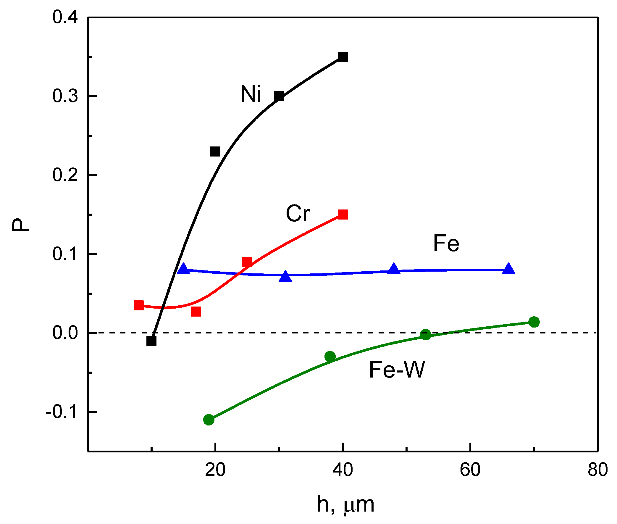
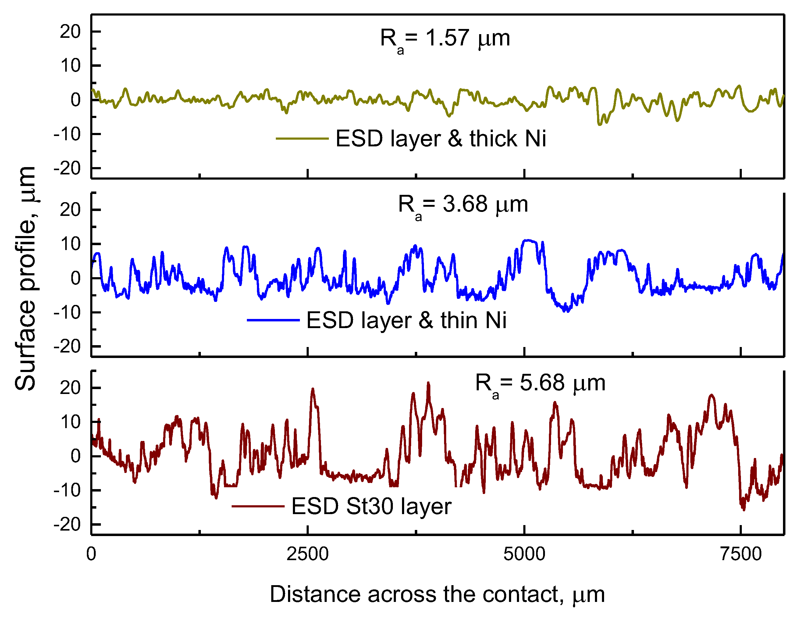
3.1. Leveling Power of Investigated Electrolytes

One of the ways to reduce the roughness of the surfaces obtained by ESD is to electrodeposit another layer from the electrolyte that possesses a high leveling power. Leveling power (P) describes the distribution of the electrodeposition rate of a metal/alloy over the cathodic microprofile. The microdistribution has a nonuniform character which appears due to the uneven availability of the microprofile for the diffusion. Diffusion limitations can occur both for the deposited metal ions and for some other of the electrolyte’s components (e.g., hydrogen, other molecules/ions from the electrolytes forming on the anode) that could affect the electrodeposition kinetics and uniformity of the deposited layer, including inhibition of the electrodeposition process by adsorption of any organic compounds present in the electrolyte at a rate sufficient for its inhibiting action to become diffusion controlled. Thus, the inhibition might be different on certain parts of the surface that are unequally accessible for diffusion. All these considerations are effective if the parameters of the cathode microprofile (depth and distances between asperities) are close to a diffusion layer (usually ca. 10 µm). Therefore, the leveling power is a multivariable parameter that for any given electrolyte can only be evaluated experimentally.
Thus, the micro-leveling power can be expressed as the distribution of the thickness of the deposit along the surface profile and its value can be positive (P > 0) or negative (P < 0) depending on the evolution of the microprofile of the electrodepositing coating from the given solution.
When P > 0, the electrodeposit grows predominantly in the grooves (valleys) compared to the microprotrusions, and consequently the initial profile is leveled. The micro-leveling power (P) of the electrolytes for the deposition of nickel, chromium, iron and Fe-W alloy was evaluated (Figure 1). The performed investigation showed that the maximum micro-leveling power (maximal values of P) was obtained for Ni electrodeposition in comparison to the other studied electrolytes. This can be related to a higher hydrogen evolution rate in the cases of Fe-W, Fe and Cr deposition. The leveling effect of nickel was evident when the thickness of it exceeded 10 μm on the surfaces with a sinusoidal profile.
In order to obtain hybrid coatings with decreased roughness, the combination of ESD with electrodeposited Ni was chosen based on the nickel leveling effect. The measured roughness, Ra of the hybrid coatings (see Table 2) also proved the positive leveling power of the Ni electrolyte. Namely, the surface roughness of all samples tended to decrease even after a short deposition time (12 min). Moreover, by electrodeposition of thicker Ni layers, the leveling effect was even more pronounced (see Table 2 and Figure 2). Because of the poor leveling effect of Fe-W alloys and Fe, these materials were not used in further investigations of hybrid coatings.

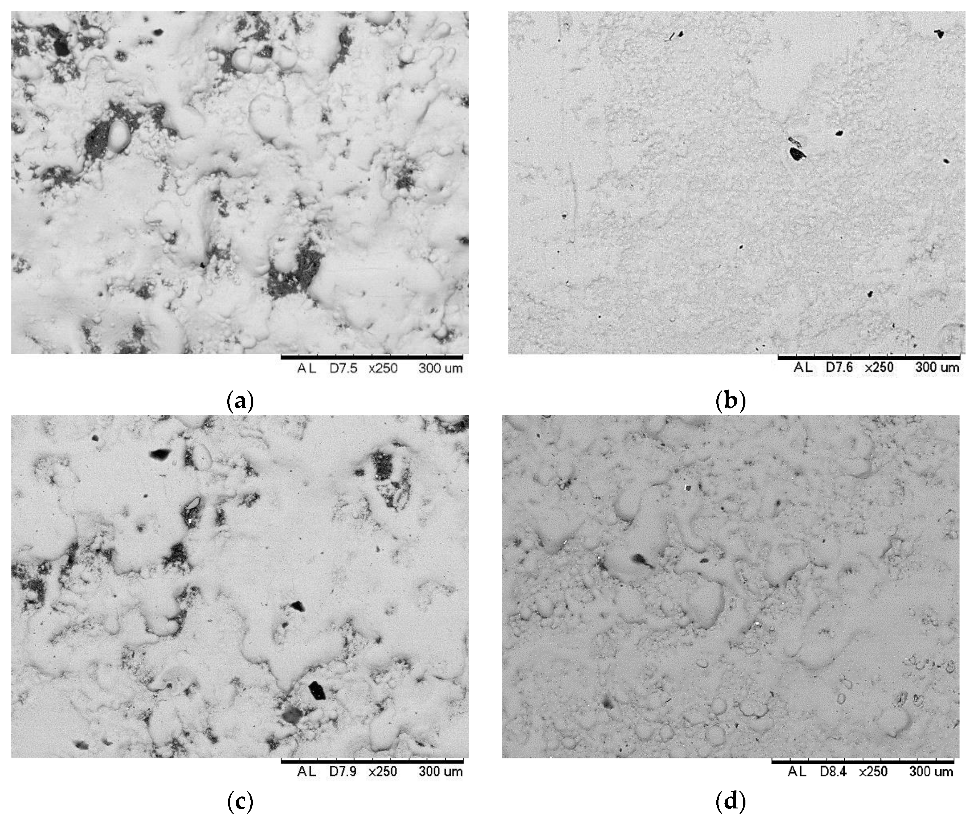
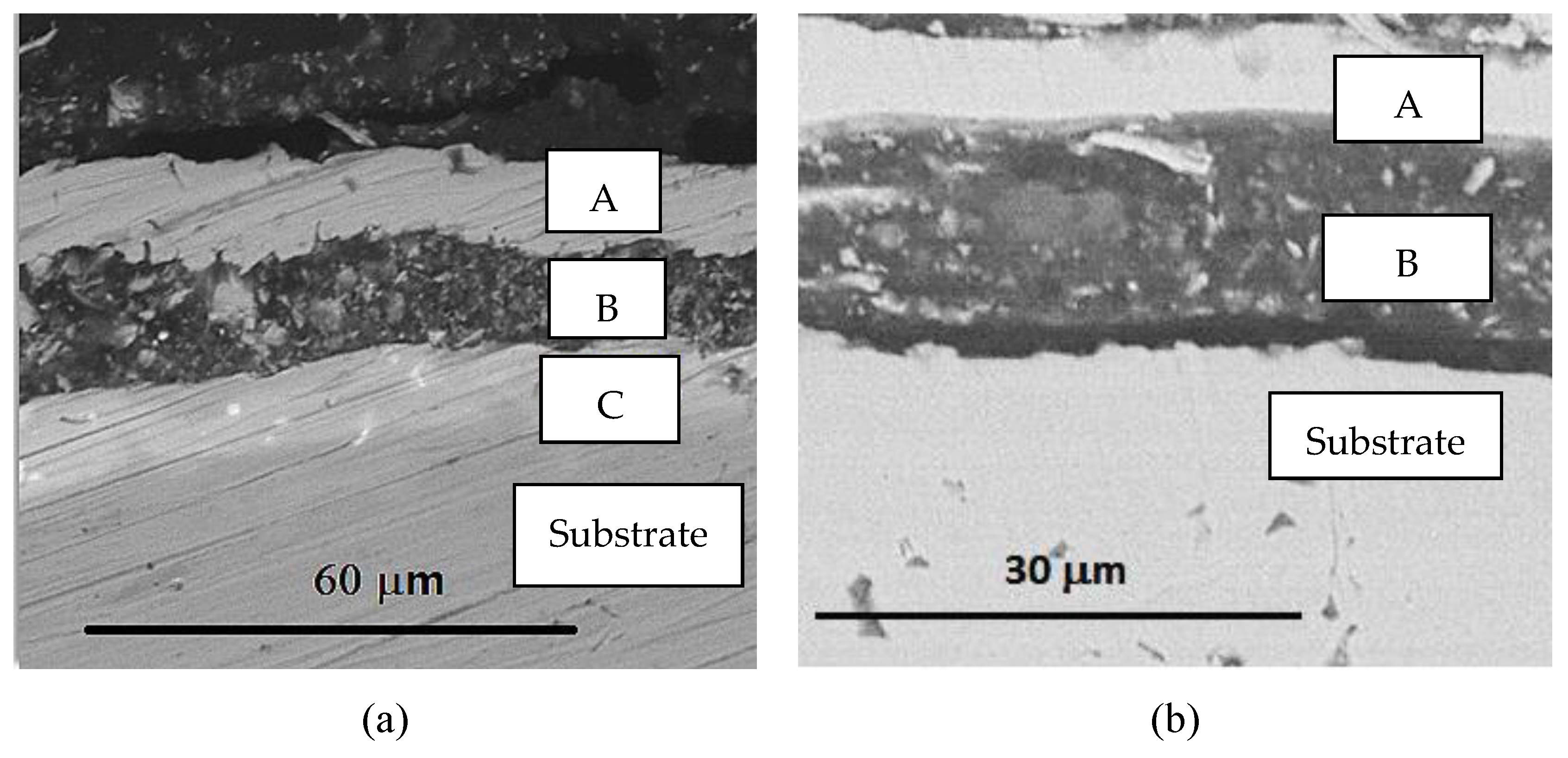
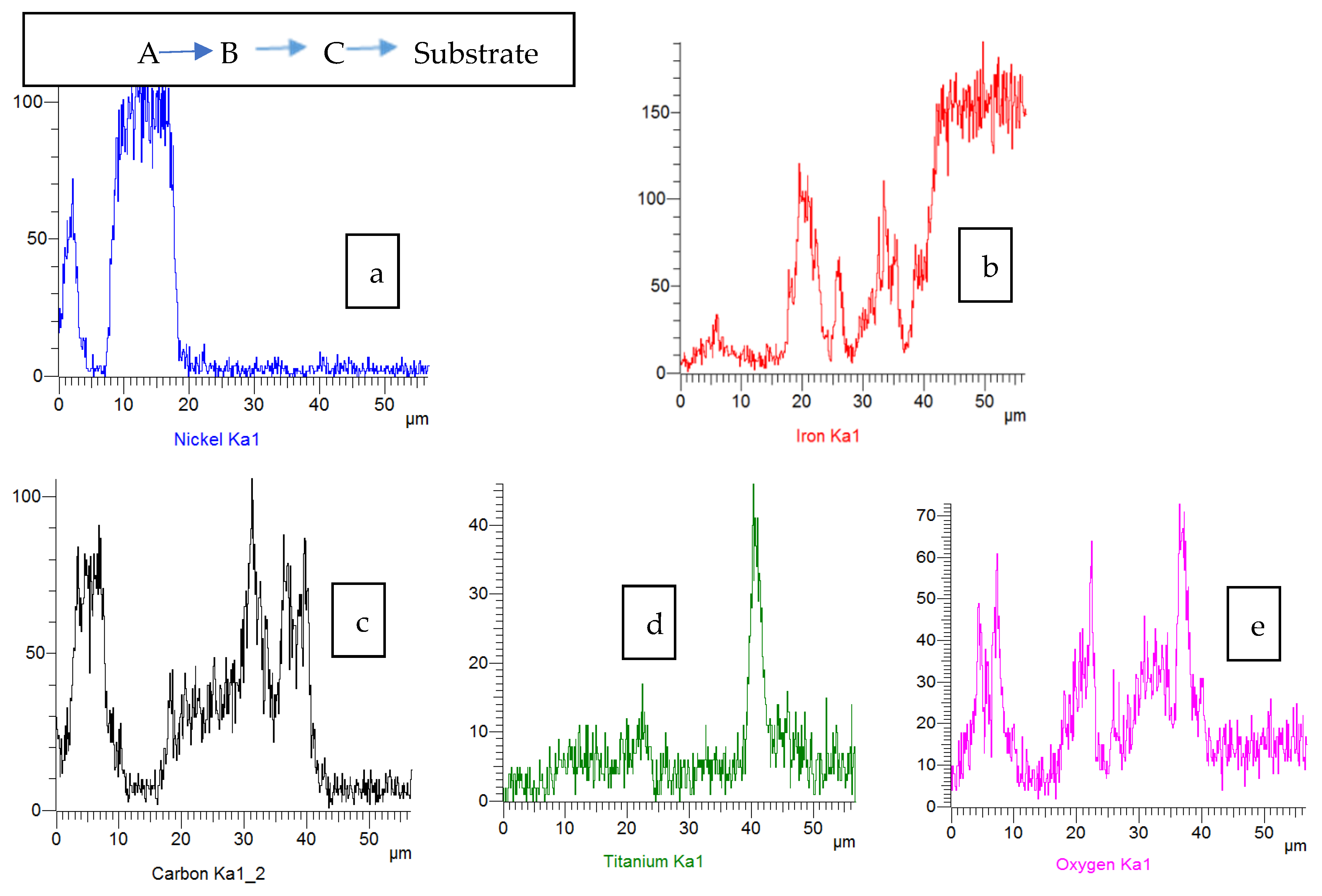
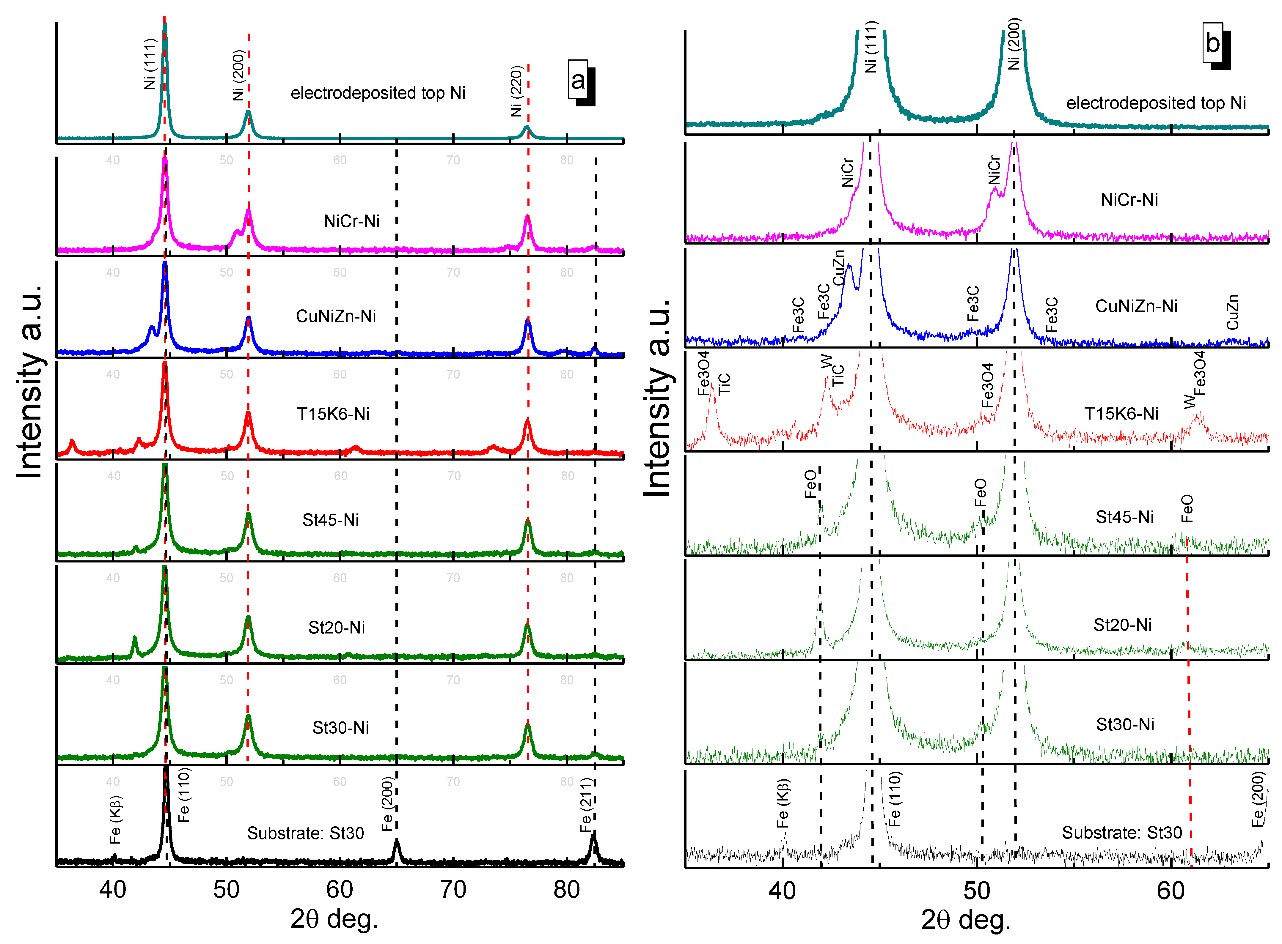
3.2. Surface Morphology, Composition and Structure of ESD-Ni Hybrid Coatings

The morphology of some hybrid coatings with “thin” deposited Ni is presented in Figure 3. It can be seen that morphology of these samples reflects the results obtained for surface roughness. Namely, the surface morphology of hybrid coatings synthesized using T15K6 hard alloy or NiCr was rather irregular (Figure 3a,c) in comparison to the more uniform surface obtained by deposits obtained using the CuNiZn electrode (Figure 3b) or the carbon steel St30 electrode (Figure 3d). Moreover, CuNiZn has minimal roughness and high degree of Ni coverage in comparison with the other obtained hybrid coatings, probably due to less oxidation of the surface after the electrospark treatment.
A cross-sectional investigation of the samples was also performed (Figure 4), including the elemental semi-quantitative line-scan analysis (Figure 5). Three layers could be detected on T15K6-Ni cross-section (Figure 4a), consisting of electrodeposited Ni (A), and two layers appearing after ESD treatment (B and C). The layer C is a so-called “white layer”, which is formed between the substrate and the electro-spark layer. It forms during each electrical discharge that generates heat energy in a narrow area that melts, evaporates and even ionizes the work-piece material. Some of the melted and all of the evaporated material is then quenched and flushed away by dielectric liquid and the remaining melt recast on the finished surface.
The recast layer is referred to as a “white layer” [32]. However, the layer C does not necessarily occur in all ESD processes (e.g., Figure 4b), but only in some cases and is based on the displacement of the electrode with respect to the substrate. This is an intermediate and non-uniform region. Generally, when the deposition is performed manually, it is difficult to calculate the overlap percentage, as this depends on the movement speed of the electrode [6]. Moreover, the novel ESD and hybrid coatings based on carbon steels and Ni are much more uniform and compact (Figure 4b).
Furthermore, the components of one layer often penetrate into another (Figure 5) due to roughness propagation during the ESD layer-deposition process. Thus, in the composition of the electrodeposited Ni layer (B), the elements of the second layer may be present as Fe and C. Apparently, this is a consequence of high roughness in the ESD layer and the measurement limits of EDX analysis (a few microns).
In order to gain a more comprehensive knowledge of the structure and composition of the fabricated hybrid coatings, XRD analysis was employed (Figure 6). The top electrodeposited Ni layer of the hybrid coatings was investigated by the grazing angle XRD method to distinguish its peaks from the ESD layers below. In the XRD pattern of the top Ni layer (Figure 6a), the crystallographic planes (111), (200), and (220) of the cubic structure of Ni (ICDD # 00-004-0850) were present (corresponding peaks are at 2θ = 44.51, 51.85, and 76.37°). Moreover, the Ni layer deposited on the ESD coatings consisted of 11.3 ± 0.5 nm crystallites (determined by the Halder–Wagner method), and the mentioned nanocrystalline Ni peaks were observed in all studied coatings (Figure 6).
Furthermore, in order to differentiate the peaks appearing from the substrate St30 (Figure 6a, bottom pattern) and coating, the XRD pattern of the St30 was recorded. The XRD pattern of the substrate indicated a cubic Fe structure (ICDD # 00-006-0696) with high intensity peaks at 2θ = 44.67, 65.02 and 82.33°. The Fe (Kβ) peak at 2θ = 40.2° appeared due to high-power X-ray radiation.
The abovementioned data obtained on the position and intensities of the diffraction peaks of St30 substrate and the top Ni layer were essential for further investigation of chemical compounds formed during the layers’ fabrication by the electro-spark method. Here, it should be mentioned that for studies of deeper electrospark deposited layers Bragg–Brentano geometry matched optics was used.
It was found (Figure 6b) that the ESD layers of the hybrid coatings obtained using St30, St20 and St45 electrode tools contained a small amount of Fe0.92O (ICDD # 04-011-7333) (corresponding diffraction peaks at 36.08, 41.9, and 60.75°). Moreover, based on the intensities of the peaks, it can be concluded that the maximum amount of FeO was formed in the St20-Ni hybrid coating.
The formation of the T15K6-Ni hybrid coating (Figure 6b) was characterized by additional XRD peaks, which could be attributed to Fe3O4 (ICDD # 04-025-3486), W (ICDD # 00-004-0806) and TiC (ICDD # 01-080-4397). Their appearance is a natural consequence of the use of T15K6 hard alloy for ESD. Furthermore, the peaks attributed to these compounds were broad, which indicated that they were composed of nanocrystallites (below 4 nm) and had very close crystal lattice parameters, which complicates the exact assignment of the peaks.
The XRD pattern of the CuNiZn-Ni coating was characterized by the appearance of diffraction peaks at 2θ = 43.4 and 63.05°, which could be attributed to Cu0.57Zn0.43 (ICDD # 04-021-2017). In addition, a small amount of Fe3C (ICDD # 00-003-0400) may have been formed during the preparation of this coating, as the weak diffractions peaks were visible for this compound.
The XRD pattern of the obtained NiCr-Ni and Ni-Ni coatings (Figure 6b) were similar in terms of structural changes. The diffraction peaks of the formed alloys/solid solutions had shifts towards smaller 2θ diffraction angles compared to the peaks of the electrodeposited Ni layer (and St30 substrate), which indicates that compounds with higher crystal lattice parameters were formed. These alloys can be matched with Cr0.4Ni0.6 (ICDD # 04-001-3422) for NiCr-Ni and Fe0.64Ni0.36 (ICDD # 00-047-1405) for Ni-Ni coatings, respectively.

3.3. Wear and Corrosion Resistance of Hybrid Coatings
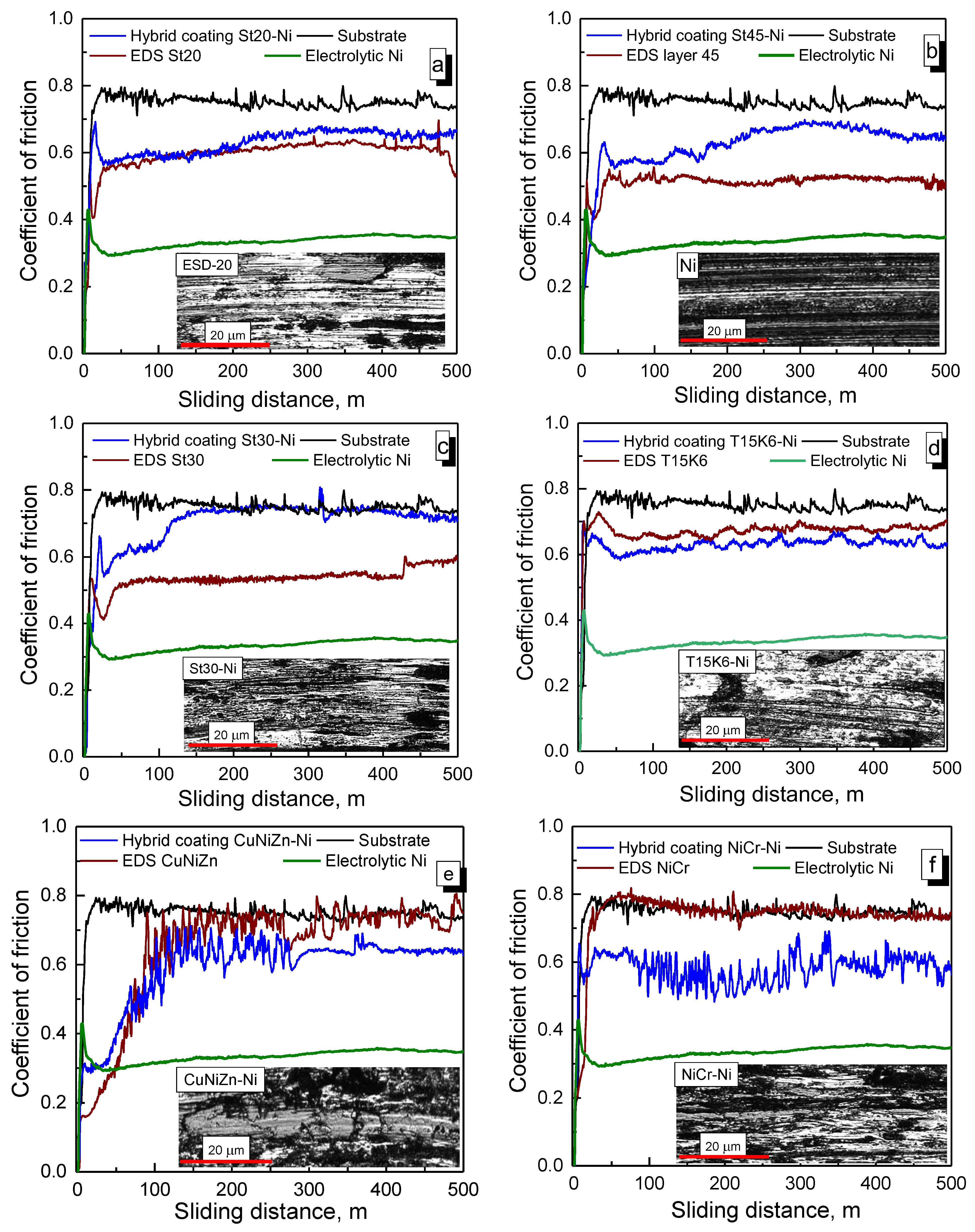
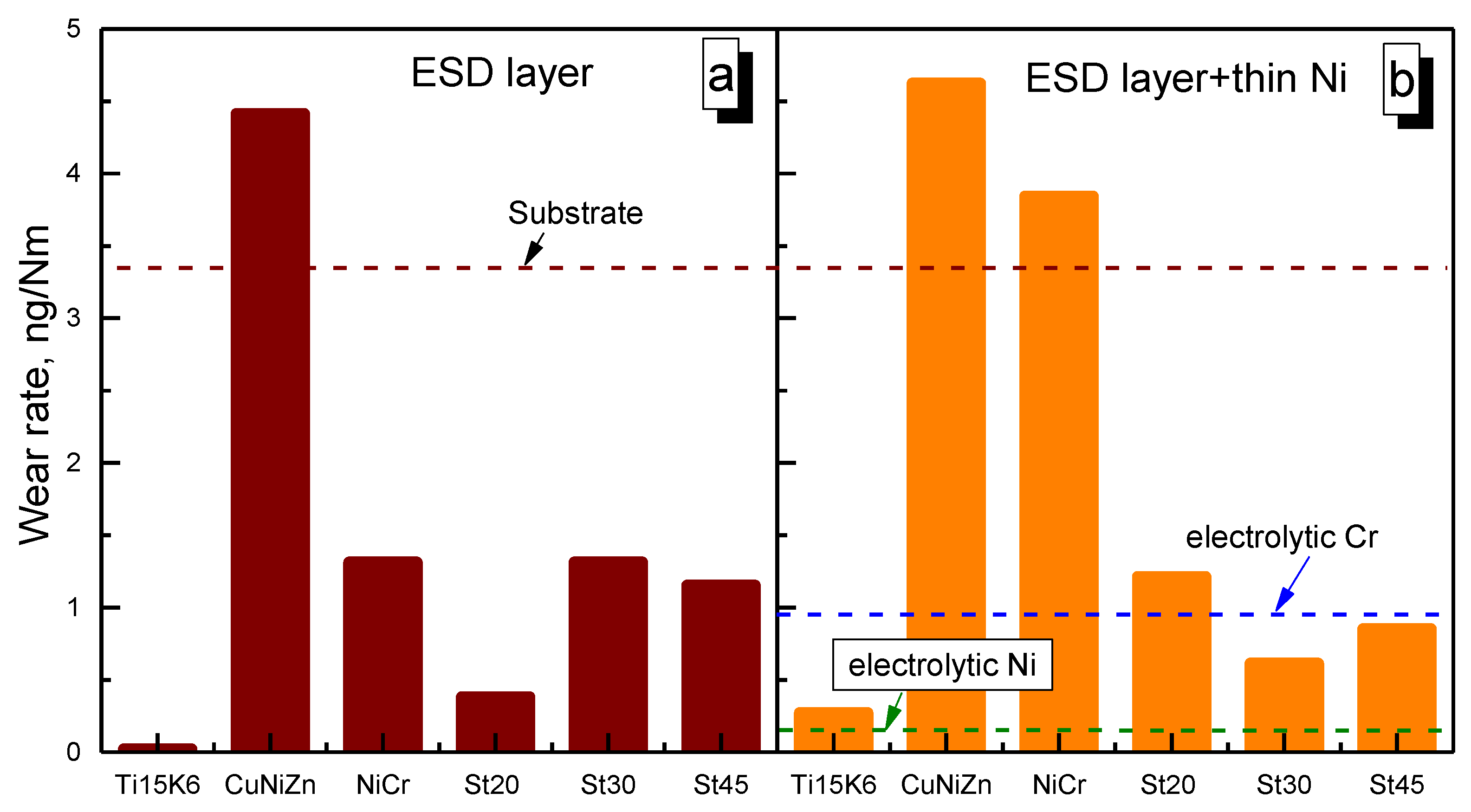
3.3.1. Wear Tests

The friction behavior (Figure 7) and wear rate (Figure 8), measured as weight loss after total sliding distance of 500 m and an applied load of 10 N, were evaluated for the synthesized coatings under unlubricated conditions and ball-on-disk configuration. Furthermore, to the best of our knowledge, this is the first attempt to design and evaluate the wear of ESD and hybrid coatings based on carbon steels, as normally they are only used as substrate material. In order to investigate the wear behavior of the hybrid coatings, the “thin” Ni (~4.5 µm) was electrodeposited on the top of the ESD layer. Moreover, as discussed above (Figure 2, Table 2), the roughness decreased only slightly when “thin” Ni was deposited. Thus, similar surface conditions for ESD and hybrid coatings could be expected. Therefore, the obtained coatings “as-deposited” were investigated.
The evaluation of the coefficient of friction for EDS, hybrid coatings, reference materials such as substrate, and electrodeposited Ni is shown in Figure 7. In general, a running-in period appeared for all tested materials. The investigated ESD coatings based on carbon steels (Figure 7 a–c) had common friction behavior, linked to the presence of the FeO phase (Figure 6) in their structure. Namely, after ~25 m of sliding distance, the coefficient of friction dropped markedly (Figure 7a–c), probably due to the oxidation of FeO into Fe3O4, which is known for its lubricating properties [33]. Moreover, as can be seen in the example of the ESD-St20 coatings (Figure 7a, inset), the oxidized part of the wear track (dark sports) was not present on the entire area of wear track, but a larger part remained intact (white areas) even at the end of the wear test. This could be attributed to superior wear resistance (Figure 8), but also to the role of the high roughness of these coatings.
A similar effect of decrease in the coefficient of friction, but after ~50 m of sliding, could be depicted for the case of the ESD coatings based on T15K6 (Figure 7d), which could also be attributed to the Fe3O4 presence in the coating (Figure 6). Here, it should be noted that the hard phases (TiC, W) present in these coatings will have an impact on the coefficient of friction due to the interaction with the hard corundum counterbody, which leads to a less pronounced decrease in the coefficient of friction (Figure 7d) compared to the coatings based on carbon steels.
Furthermore, a decrease in the coefficient of friction at the beginning of the wear test for the novel hybrid coatings and the electrodeposited Ni could be attributed to the formation of nickel oxides. It could be suggested that the heat generated during the dry-sliding wear test resulted in an increase in the interfacial temperature between the corundum and the electrodeposited Ni. Indeed, nickel-containing coatings can easily oxidize and form a stable nickel oxide layer [34]. Thus, these coatings demonstrated quite pronounced oxidative wear or tribo-oxidation, which was optically visible throughout the wear track (see Figure 7b, inset).
Moreover, when comparing the ESD and Ni hybrid coatings based on carbon steels, it was noted that the ESD coatings had a lower coefficient of friction than the hybrid ones (Figure 7a–c). Probably, this can be related to the interplay of iron and nickel oxides in the case of hybrid coatings. In contrast, the addition of Ni decreased the coefficient of friction for the T15K6 hybrid coating (Figure 7d), but the wear rate was higher for this coating than for its ESD counterpart (Figure 8). This could be attributed to a higher degree of oxidation of the hybrid coating (Figure 7d, inset) than for the electrospark ones, which were practically intact during the friction test.
After the running-in period, for all investigated cases, the coefficient of friction mostly reached the steady state value. However, in the case of the ESD and hybrid coatings based on CuNiZn, a longer running-in period and the smallest starting coefficient of friction were noted (Figure 7e), which could be linked to the presence of soft phases as CuZn and NiO in this coating (Figure 6). Furthermore, it could be seen that a pronounced scattering in the first 300 m was characteristics for these coatings. The last could be attributed to the continuous interaction of soft and hard phases as Fe3C (Figure 6) in these ESD and hybrid coatings with the counterbody. Fe3C is known for its mechanical properties [35], but coupling to soft phases leads to accumulation and plastic deformation of debris inside the wear track (Figure 7e, inset) and three-body abrasive wear, leading to the highest wear rates (Figure 8).
A similar wear mechanism was realized for the NiCr-Ni hybrid coating, where high scattering was noted throughout the whole duration of the wear test (Figure 7f). Although, as was shown in [36], the addition of metal oxide to the NiCr phase results in the decrease in the coefficient of friction and an improvement of the wear resistance. In the present study, the NiCr-Ni hybrid coating had a high degree of visible oxidation inside the wear track (Figure 7f, inset) and thus, a lower coefficient of friction in comparison to the ESD coating (Figure 7f); however, the wear resistance of the hybrid coating decreased (Figure 8).
Among all the ESD coatings, deposits based on T15K6 and carbon steels exhibit the highest wear rate (Figure 8a). Here, it should be specified that the ESD St20 coating had the highest wear resistance of the carbon steels used, probably due to a higher amount of FeO in the coating (Figure 6b) and the wear rate for this coating was even lower than for electrolytic hard chromium (Figure 8). The hybrid coatings were manifesting a lower wear rate in comparison to their ESD counterparts (Figure 8b). However, in the case of St45-Ni and St30-Ni coatings, the wear resistance was improved, especially for the St30 case. This could be attributed to the more uniform coverage of the ESD layer by electrodeposited Ni for St30-Ni coating (Figure 3d) and a higher oxidation degree inside the wear track (Figure 7c, inset). Remarkably, the electrodeposited Ni coating had a very low wear rate (Figure 8b), which approached the values of the T15K6 hard coatings.
Moreover, this study reflects the possibilities that can be associated with the use of carbon steels as an electrode tool for the design of new coatings. However, future experiments would generate more insight into the actual applications for these coatings.

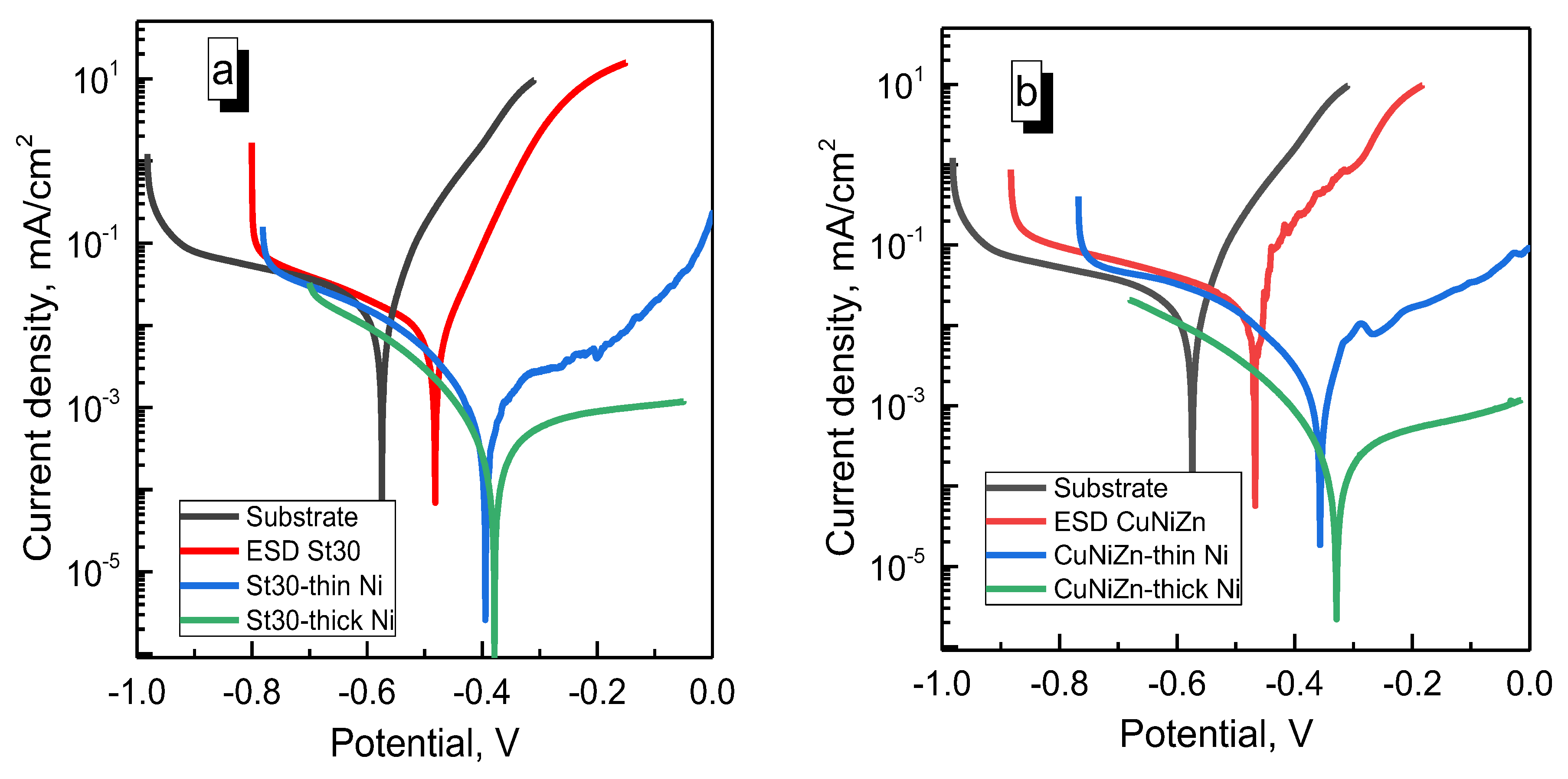
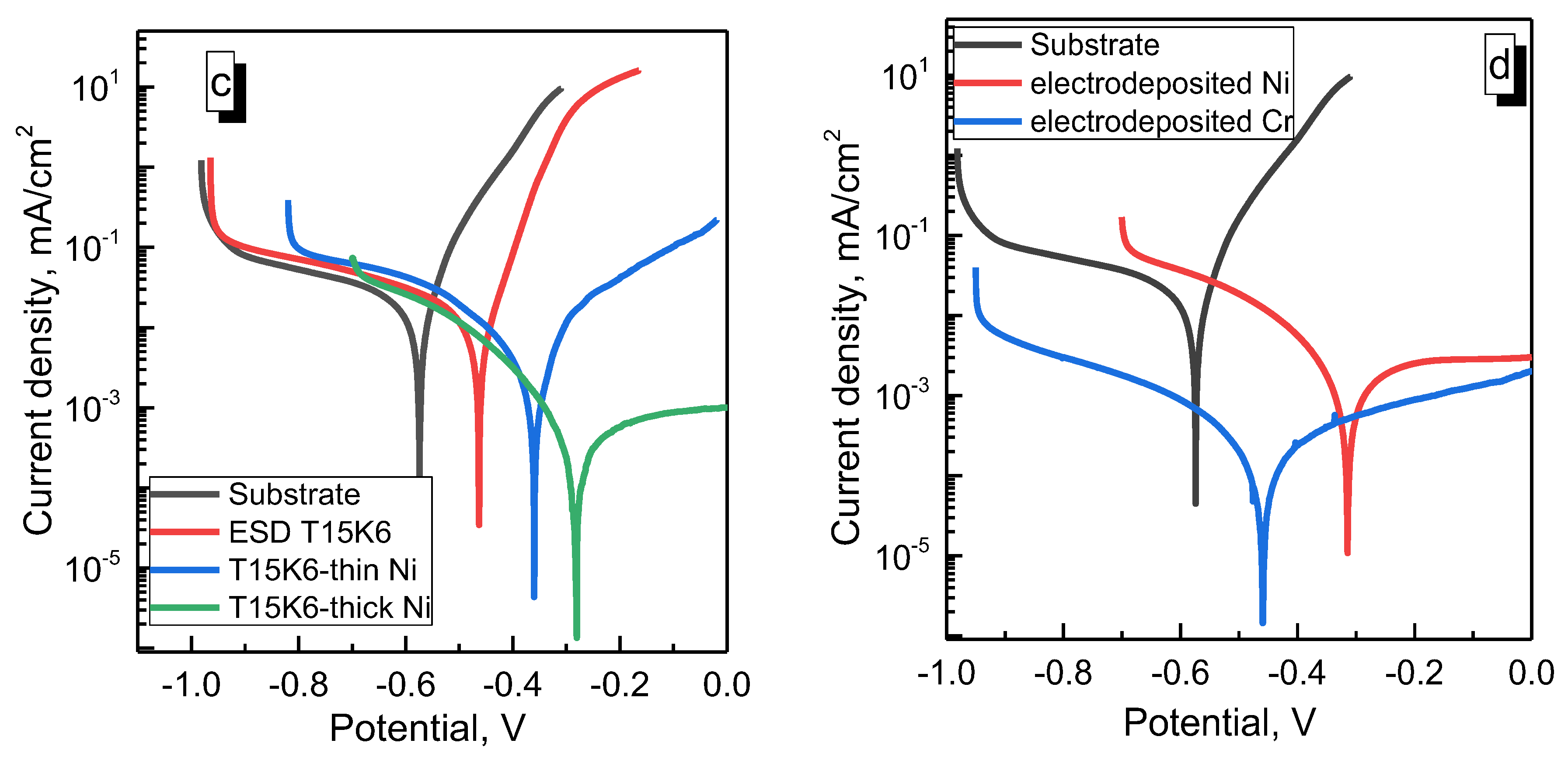
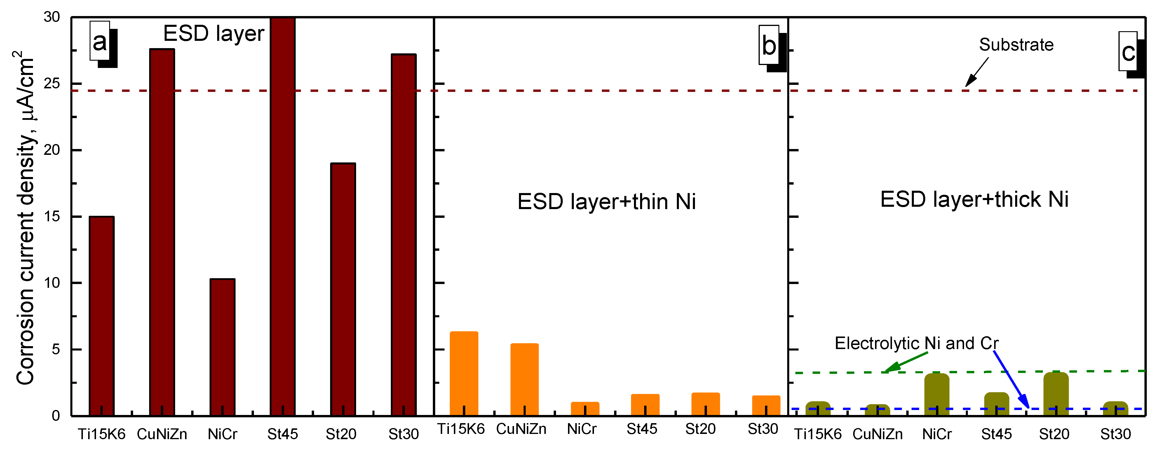
3.3.2. Corrosion Tests

The composition, microstructure and density of the deposits are dependent on the preparation methods and conditions. The variation in the corrosion rates and other properties of the surfaces with their fabrication method and structure are well known [37,38]. Therefore, examination of the corrosion properties of the obtained materials is an integral part of modern materials science.
There were two types of hybrid coatings used for the corrosion tests: “thin” and “thick” electrodeposited layers of Ni. The typical Evans diagrams obtained for the examined ESD and hybrid coatings in the 3.5% NaCl solution are shown in Figure 9. In addition, for the comparison of the corrosion properties, the coatings of Ni and Cr were electrodeposited on the substrate (see Figure 9d); also, the corrosion of the substrate was investigated. As can be seen, the corrosion potential for the ESD and hybrid coatings were essentially shifted toward more positive values in comparison with the ones for the substrate: even the thin Ni layer electrodeposited onto ESD coating caused the shift of corrosion potential to more positive values by 100 mV that may have indicated the decrease in corrosion rate.
The extracted corrosion current densities for all the investigated systems are summarised in Figure 10. Notably, the obtained corrosion current density for nickel electrodeposited on the substrate was higher than that obtained under similar conditions in [39] (i.e., ~0.8 μA/cm2 calculated using the provided data of electrochemical impedance spectroscopy). The difference in corrosion current densities was probably caused by the higher initial roughness of substrate and coatings than in the cited work.
As seen in Figure 10a, the ESD coatings of Ti15K6, Ni-Cr and St20 possessed a lower corrosion current than the substrate applied. In the other cases, the corrosion currents for the ESD coatings were higher than for the substrate even if the material of both the substrate and anode for the coating by ESD was the same (St30). Actually, the ESD coating contained some small amount of FeO (see XRD data in Figure 6) that did not reinforce the iron matrix, and the included particles did not act as a physical barrier to the propagation of defects, similar to [40].
In contrast, the presence of iron oxide particles in the metallic matrix probably formed galvanic microcells, which increased the dissolution of the iron matrix, and with the increased roughness of the ESD-coating surface resulted in the initiation of local corrosion and an increase in the apparent corrosion current density.
However, the corrosion current densities became essentially lower for hybrid coatings compared to ESD coatings (see Figure 9a–c and Figure 10b,c). Even the electrodeposited thin Ni layer caused a decrease in corrosion current densities of up to 10 times for the hybrid coatings based on ESD layers of St20, St30, St45, and NiCr (see Figure 10b). Such values of corrosion current densities for hybrid coatings were lower than for electrodeposited nickel (see Figure 10b) and were compatible with the corrosion current density obtained for electrolytic chromium. Probably, some galvanic microcouples were formed resulting in a decrease in the apparent corrosion current density. When a thicker layer of Ni was electrodeposited onto the ESD coating of NiCr and St20, the corrosion current density became equal to the corrosion current densities obtained for thick electrodeposited nickel onto a substrate. Probably, on these ESD layers, dense, non-porous coatings of Ni were formed, and the electrochemical properties of the surface were governed by an entire nickel film. The essential decrease in apparent corrosion current densities was obtained for the hybrid coatings based on ESD layers of T15K16, CuNiZn and St45 and St20. In these cases, the decrease in corrosion current densities may be linked to the smoother surface (smaller values of roughness) obtained when Ni was electrodeposited onto the rough ESD layer, i.e., linking to the leveling effect of nickel deposition.

4. Conclusions

This study was devoted to new possibilities of using carbon steels as electrode tools for the design of new electrospark and novel hybrid (electrospark–electrochemical) coatings. It was shown that carbon steels can be successfully applied to obtain ESD coatings that possess reasonable wear resistance comparable to electrolytic chromium and even ESD-St20 coating may be close to hard ESD coating based on T15K6. The design of the electrospark–electrochemical hybrid coatings was related to the possibility of electrolytes causing a leveling effect on the surface profile, thus decreasing the roughness of ESD coatings.
It was found that the Ni electrodeposited from Watts electrolyte could manifest the highest microleveling power and effectively decrease the roughness of electrospark deposits by up to four times. However, the oxidation of the nickel during the friction tests led to ambiguous behavior by the tested coatings. Namely, nickel oxide appeared to interact with the other phases present or generated during the wear tests (e.g., Fe3O4, Fe3C, TiC), which, except for the St30-Ni coating, led to more pronounced tribo-oxidation wear in the case of the hybrid coatings.
In contrast to wear, the corrosion resistance was improved considerably for all the studied hybrid coatings in comparison to ESD. Remarkably, not only a thick deposit of Ni, but even a thin ~4.5 µm layer could decrease the corrosion current density of the ESD coatings by up to 15 times. The acquired data clearly show that ESD coatings based on carbon steels can be successfully used as a wear-resistant material under dry friction, and hybrid coatings for tribo-corrosion applications. However, future experiments would generate more insight into the actual potential of these coatings.

Author Contributions

Investigation, I.B., S.S., N.T., V.P. (Vladimir Petrenko) and V.P. (Vidas Pakstas); methodology and planning of experiments, A.D., S.S. and N.T.; visualization, N.T. and S.S.; writing—original draft preparation, N.T. and H.C.; writing—review and editing, all authors. All authors have read and agreed to the published version of the manuscript.

Funding

This research was funded by the European Union’s Horizon 2020 research and innovation programme under the MSCA grant №778357- SMARTELECTRODES, and partially from the ANCD project (Moldova) 20.80009.5007.18, as well as a budget funding from Pridnestrovian State University “T.G.Shevchenko”.

Conflicts of Interest

The authors declare no conflict of interest.

References

  1. Fotovvati, B.; Namdari, N.; Dehghanghadikolaei, A. On Coating Techniques for Surface Protection: A Review. J. Manuf. Mater. Process. 2019, 3, 28. [Google Scholar] [CrossRef]
  2. Zielinski, A.; Bartmanski, M. Electrodeposited Biocoatings, Their Properties and Fabrication Technologies: A Review. Coatings 2020, 10, 782. [Google Scholar] [CrossRef]
  3. Felix, L.M.; Kwan, C.C.; Zhou, N.Y. The Effect of Pulse Energy on the Defects and Microstructure of Electro-Spark-Deposited Inconel 718. Metall. Mater. Trans. A 2019, 50, 4223–4231. [Google Scholar] [CrossRef]
  4. Lazarenko, B.R.; Lazarenko, N.I. Electrospark Machining of Metals; US Cons Bureau: New York, NY, USA, 1964. [Google Scholar]
  5. Renna, G.; Leo, P.; Casalino, G.; Cerri, E. Repairing 2024 Aluminum Alloy via Electrospark Deposition Process: A Feasibility Study. Adv. Mater. Sci. Eng. 2018, 2018, 8563054. [Google Scholar] [CrossRef]
  6. Barile, C.; Casavola, C.; Pappalettera, G.; Renna, G. Advancements in Electrospark Deposition (ESD) Technique: A Short Review. Coatings 2022, 12, 1536. [Google Scholar] [CrossRef]
  7. Cao, G.; Zhng, X.; Tang, G.; Ma, X. Microstructure and corrosion behavior of Cr coating on M50 steel fabricated electrospark deposition. J. Mater. Eng. Perfom. 2019, 28, 4086–4094. [Google Scholar]
  8. Rukanskis, H. Control of metal surfaces mechanical and tribological characteristics using cast effective electrospark deposition. Surf. Eng. Appl. Electrochem. 2019, 55, 607–619. [Google Scholar] [CrossRef]
  9. Topala, P.; Ojegov, E.; Ursaki, V. Nanostructures of obtaining using electric discharges at atmospheric pressure. In Nanostructures and Thin Films of Multifunctional Applications; Tigineanu, I., Topala, P., Ursaki, V., Eds.; Springer International Publishing AG: Berlin/Heidelberg, Germany, 2016; pp. 43–83. [Google Scholar]
  10. Padgurskas, J.; Kreivaitis, R.; Rukuiža, R.; Mihailov, V.; Agafii, V.; Kriūkienė, R.; Baltušnikas, A. Tribological properties of coatings obtained by electro-spark alloying C45 steel surfaces. Surf. Coat. Technol. 2017, 311, 90–97. [Google Scholar] [CrossRef]
  11. Myslyvchenko, O.; Gaponova, O.; Tarelnyk, V.; Krapivka, M.O. The Structure Formation and Hardness of High-Entropy Alloy Coatings Obtained by Electrospark Deposition. Powder Metall. Met. Ceram. 2020, 59, 201–208. [Google Scholar] [CrossRef]
  12. Sheveyko, A.N.; Kuptsov, K.A.; Kiryukhantsev-Korneev, P.V.; Kaplansky, Y.Y.; Orekhov, A.S.; Levashov, E.A. Protective coatings for LPBF Ni-based superalloys using a combination of electrospark deposition and pulsed arc evaporation methods. Appl. Surf. Sci. 2022, 581, 152357. [Google Scholar] [CrossRef]
  13. Vizureanu, P.; Perju, M.; Achitei, D.; Nejneru, C. Advanced Electro-Spark Deposition Process on Metallic Alloys. In Advanced Surface Engineering Research; Chowdhury, M.A., Ed.; IntechOpen: London, UK, 2018; pp. 45–68. [Google Scholar]
  14. Paustovskii, A.V.; Tkachenko, Y.G.; Alfintseva, R.A.; Kirilenko, S.N.; Yurchenko, D.Z. Optimization of the composition, structure, and properties of electrode materials and electrospark coatings for strengthening and reconditioning of metal surfaces. Surf. Engin. Appl. Electrochem. 2013, 49, 4–12. [Google Scholar] [CrossRef]
  15. Levashov, E.A.; Malochkin, O.V.; Kudryashov, A.E.; Gammel, F.; Suchentrunk, R. Effects of nanocrystalline powders additions on the characteristics of combustion process, phase and structure-formation, and properties of SHS alloys on titanium carbide base. J. Mater. Synth. Process. 2002, 10, 231–236. [Google Scholar] [CrossRef]
  16. Celis, J.P.; Drees, D.; Huq, M.Z.; Wu, P.Q.; De Bonte, M. Hybrid processes—A versatile technique to match process requirements and coating needs. Surf. Coat. Technol. 1999, 113, 165–181. [Google Scholar] [CrossRef]
  17. Gleiter, H. Nanostructural materials: Basic concepts. Acta Mater. 2000, 48, 1–29. [Google Scholar] [CrossRef]
  18. Onishchenko, D.V.; Reva, V.P.; Kuryavyi, V.G.; Petrov, V.V.; Kim, V.A. Innovative Technology for Forming Hard Alloy T15K6 Using Amorphous Carbon from Renewable Plant Raw Material. Metallurgist 2013, 57, 548–552. [Google Scholar] [CrossRef]
  19. Dobruchowska, E.; Koprowska, J. Corrosion Behaviour of CuSn- and CuZnNi-coated Polypropylene Nonwoven. Fibres Text. East. Eur. 2006, 24, 72–78. [Google Scholar] [CrossRef]
  20. Yu, H.; Shi, H.X.; Wang, Y.L.; Zhang, K.K.; Wang, W.Y.; Han, L.J.; Pang, Q.H. NiCr alloy coating deposited on the surface of 35CrMo steel by the electrospark process. Mater. Sci. Forum 2008, 575–578, 827–832. [Google Scholar] [CrossRef]
  21. Kozyr, A.; Konevtsov, L.; Konovalov, S.; Kovalenko, S.; Ivashenko, V. Research on heat resistance properties of coatings deposited by electrospark alloying on steel C45 by nickel-chromium alloys. Lett. Mater. 2018, 8, 140–145. [Google Scholar] [CrossRef]
  22. Bobanova, Z.; Petrenko, V.; Tsyntsaru, N.; Dikusar, A. Leveling power of Co-W and Fe-W electrodeposited coatings. Key Eng. Mater. 2019, 813, 248–253. [Google Scholar] [CrossRef]
  23. Cesiulis, H.; Tsyntsaru, N.; Podlaha, E.; Li, D.; Sort, J. Electrodeposition of iron-group alloys into nanostructured oxide membranes: Synthetic challenges and properties. Curr. Nanosci. 2018, 14, 1–16. [Google Scholar] [CrossRef]
  24. Revathy, S.; Nair, A.S.; Sreejakumari, S.S. Recent trends and developments in two-dimensional materials based electrodeposited nickel nanocomposite coatings. FlatChem 2022, 36, 100434. [Google Scholar]
  25. Zhao, H.; Liu, L.; Zhu, J.; Tang, Y.; Hu, W. Microstructure and corrosion behavior of electrodeposited nickel prepared from a sulphamate bath. Mater. Lett. 2007, 61, 1605–1608. [Google Scholar] [CrossRef]
  26. Hasanpour, P.; Salehikahrizsangi, P.; Raeissi, K.; Santamaria, M.; Calabrese, L.; Proverbio, E. Dual Ni/Ni-Co Electrodeposited Coatings for Improved Erosion-Corrosion Behaviour. Surf. Coat. Technol. 2019, 368, 147–161. [Google Scholar] [CrossRef]
  27. Yang, W.; Liang, Z.; Yang, D.; Chen, D.; Luo, X.; Xilin Luo, X.; Gong, C. Corrosion of Electrodeposited Ni Coatings of Agricultural Machinery by Farming Fertilizers. J. Mater. Eng. Perform. 2021, 30, 7275–7282. [Google Scholar] [CrossRef]
  28. Zhu, W.; Xu, Y.; Kong, D. Microstructure and Tribological Performance of Electrodeposited Cr Coating with Trivalent–Chromium Electrolyte. JOM 2022, 74, 4575–4582. [Google Scholar] [CrossRef]
  29. Wei, T.; Zhang, R.; Yang, H.; Liu, H.; Qiu, S.; Wang, Y.; Du, P.; He, K.; Hu, X.; Dong, C. Microstructure, corrosion resistance and oxidation behavior of Cr-coatings on Zircaloy-4 prepared by vacuum arc plasma deposition. Corros. Sci. 2019, 158, 108077. [Google Scholar] [CrossRef]
  30. Scinti.net. Available online: https://www.scinti.net/electrospark-treatment-edm/alier-31 (accessed on 29 March 2023).
  31. Kruglikov, S.S. Leveling Power of Electrolytes and Microgeometric Characteristics of Surfaces of Electrodeposited Metals. Russ. J. Electrochem. 2001, 37, 657–660. [Google Scholar] [CrossRef]
  32. Huang, C.A.; Hsu, F.Y.; Yao, S.J. Microstructure analysis of the martensitic stainless steel surface fine-cut by the wire electrode discharge machining (WEDM). Mater. Sci. Eng. 2004, A371, 119–126. [Google Scholar] [CrossRef]
  33. Zhou, G.; Zhu, Y.; Wang, X.; Xia, M.; Zhang, Y.; Ding, H. Sliding tribological properties of 0.45% carbon steel lubricated with Fe3O4 magnetic nano-particle additives in baseoil. Wear 2013, 301, 753–757. [Google Scholar] [CrossRef]
  34. Hatipoglu, G.; Kartal, M.; Uysal, M.; Cetinkaya, T.; Akbulut, H. The effect of sliding speed on the wear behavior of pulse electro Co-deposited Ni/MWCNT nanocomposite coatings. Tribol. Int. 2016, 98, 59–73. [Google Scholar] [CrossRef]
  35. Goel, S.; Joshi, S.S.; Abdelal, G.; Agrawal, A. Molecular dynamics simulation of nanoindentation of Fe3C and Fe4C. Mater. Sci. Eng. A 2014, 597, 331–341. [Google Scholar] [CrossRef]
  36. Medabalimi, S.R.; Ramesh, M.R.; Kadoli, R. Developing partially oxidized NiCr coatings using the combined flame spray and plasma spray process for improved wear behaviour at high temperature. Wear 2021, 478–479, 203885. [Google Scholar] [CrossRef]
  37. Bersirova, O.; Cesiulis, H.; Donten, M.; Krolikowski, A.; Stojek, Z.; Baltrunas, G. Corrosion and anodic behavior of electrodeposited Ni-Mo alloys. Physchem. Mech. Mat. 2004, 4, 620–625. [Google Scholar]
  38. Safonov, V.A.; Vykhodtseva, L.N.; Edigaryan, A.A.; Aliev, A.D.; Molodkina, E.B.; Danilov, A.I.; Lubnin, E.N.; Polukarov, Y.M. Corrosion–electrochemical behavior of chromium deposits obtained from sulfuric acid solutions containing oxalates. Russ. J. Electrochem. 2001, 37, 127–134. [Google Scholar] [CrossRef]
  39. Makarava, I.; Esmaeili, M.; Kharytonau, D.S.; Pelcastre, L.; Ryl, J.; Bilesan, M.R.; Vuorinen, E.; Repo, E. Influence of CeO2 and TiO2 Particles on Physicochemical Properties of Composite Nickel Coatings Electrodeposited at Ambient Temperature. Materials 2022, 15, 5550. [Google Scholar] [CrossRef]
  40. Shozib, I.; Ahmad, A.; Abdul-Rani, A.; Beheshti, M.; Aliyu, A. A review on the corrosion resistance of electroless Ni-P based composite coatings and electrochemical corrosion testing methods. Corros. Rev. 2022, 40, 1–37. [Google Scholar] [CrossRef]
Figure 1. The micro-leveling power (P) as a function of the thickness of Ni, Cr, Fe and Fe-W electrodeposits.
Lubricants 11 00205 g001
Figure 2. The profile of surface roughness of hybrid coatings consisting of electrodeposited thin Ni (12 min) and thick Ni (100 min) layers and the ESD layer using St30 electrode tool.
Lubricants 11 00205 g002
Figure 3. SEM images of representative hybrid coatings deposited on St30. ESD layers were obtained using T15K6 (a), CuNiZn (b), NiCr (c) and St30 (d) electrode tools.
Lubricants 11 00205 g003
Figure 4. SEM images of T15K6-Ni (a) and NiCr-Ni (b), where: A—electrodeposited Ni layer; B—ESD layer; C—“white layer”; substrate—steel St30.
Lubricants 11 00205 g004
Figure 5. Line-scan EDS analysis of elemental composition of T15K6-Ni coating demonstrating the variation of each element (Ni (a), Fe (b), C (c), Ti (d) and O (e)) across the different layers, where: A—electrodeposited Ni layer; B—ESD layer; C—“white layer”; substrate—steel St30.
Lubricants 11 00205 g005
Figure 6. XRD full patterns (a) and magnified patterns (b) of investigated hybrid coatings with top electrodeposited Ni layer and substrate (see Table 2 for the coating abbreviations).
Lubricants 11 00205 g006
Figure 7. Evolution of coefficient of friction against corundum with the total sliding distance at 10 N for: ESD and hybrid coatings, electrodeposited Ni and substrate. The insets are the optical images of the wear tracks at the end of the tests of hybrid: St20-Ni (a), St30-Ni (c), T15K6-Ni (d), CuNiZn (e) and electrodeposited Ni (b) coatings.
Lubricants 11 00205 g007
Figure 8. Wear rate of the ESD layers (a), hybrid coatings (b), also substrate and electrodeposited Ni and Cr (dashed lines) are presented for comparison.
Lubricants 11 00205 g008
Figure 9. Typical Evans diagrams obtained for ESD, hybrid and electrodeposited coatings recorded in 3.5% NaCl. The examined coatings are indicated in the legend, where electrode-tools of: St30 (a), CuNiZn (b), T15K6 (c) were used for ESD and hybrid layers, and electrodeposited Ni and Cr (d) coatings are presented for comparison.
Lubricants 11 00205 g009aLubricants 11 00205 g009b
Figure 10. Corrosion current densities in 3.5% NaCl of ESD layers (a), hybrid coatings with 12 min. deposited Ni (b), and hybrid coatings with 100 min. deposited Ni (c). Dashed lines: St30 substrate; deposited Ni (100 min) and deposited Cr (160 min).
Lubricants 11 00205 g010
Table 1. Electrospark deposition parameters and composition of electrode tools used for ESD layers.
Sample No.Electrode Material Used for ESD LayerESD Parameters
1T15K6 (WC 79 %; TiC 15 %, Co 6%)Manual mode
Pulse energy: 0.07 J;
Application speed 2.5 cm2/min;
Deposition time: 4 min.
2CuNiZn (Cu 52%, Ni 11%, Zn 33%, Mn 4%)
3Ni-Cr (Ni 79%, Cr 19%, Fe 2%)
4AISI 1045 (St45)
5AISI 1020 (St20)
6AISI 1030 (St30)
Table 2. Roughness of ESD and hybrid coatings with “thin” and “thick” electrodeposited Ni.
NoSt30 Substrate
Ra, µm
ESD LayerHybrid Coating
“thin” Ni“thick” NiAbbreviation
Electrode toolRa, µmRa, µm
10.3 ± 0.1T15K64.9 ± 0.43.8 ± 0.42.3 ± 0.2T15K6-Ni
2CuNiZn2.3 ± 0.42.5 ± 0.71.2 ± 0.2CuNiZn-Ni
3NiCr3.8 ± 0.53.1 ± 0.42.5 ± 0.1NiCr-Ni
4St453.8 ± 0.34.4 ± 0.42.3 ± 0.1St45-Ni
5St203.7 ± 0.24.7 ± 0.93.7 ± 0.3St20-Ni
6St305.7 ± 0.53.6 ± 0.61.6 ± 0.2St30-Ni
Disclaimer/Publisher’s Note: The statements, opinions and data contained in all publications are solely those of the individual author(s) and contributor(s) and not of MDPI and/or the editor(s). MDPI and/or the editor(s) disclaim responsibility for any injury to people or property resulting from any ideas, methods, instructions or products referred to in the content.

