Influence of Water Contamination, Iron Particles, and Energy Input on the NVH Behavior of Wet Clutches

 , , , , ,
  ,
,  and
and 
Abstract
:1. Introduction
1.1. Motivation and State of the Art
1.2. Research Objective
2. Experimental Setup and Methodology
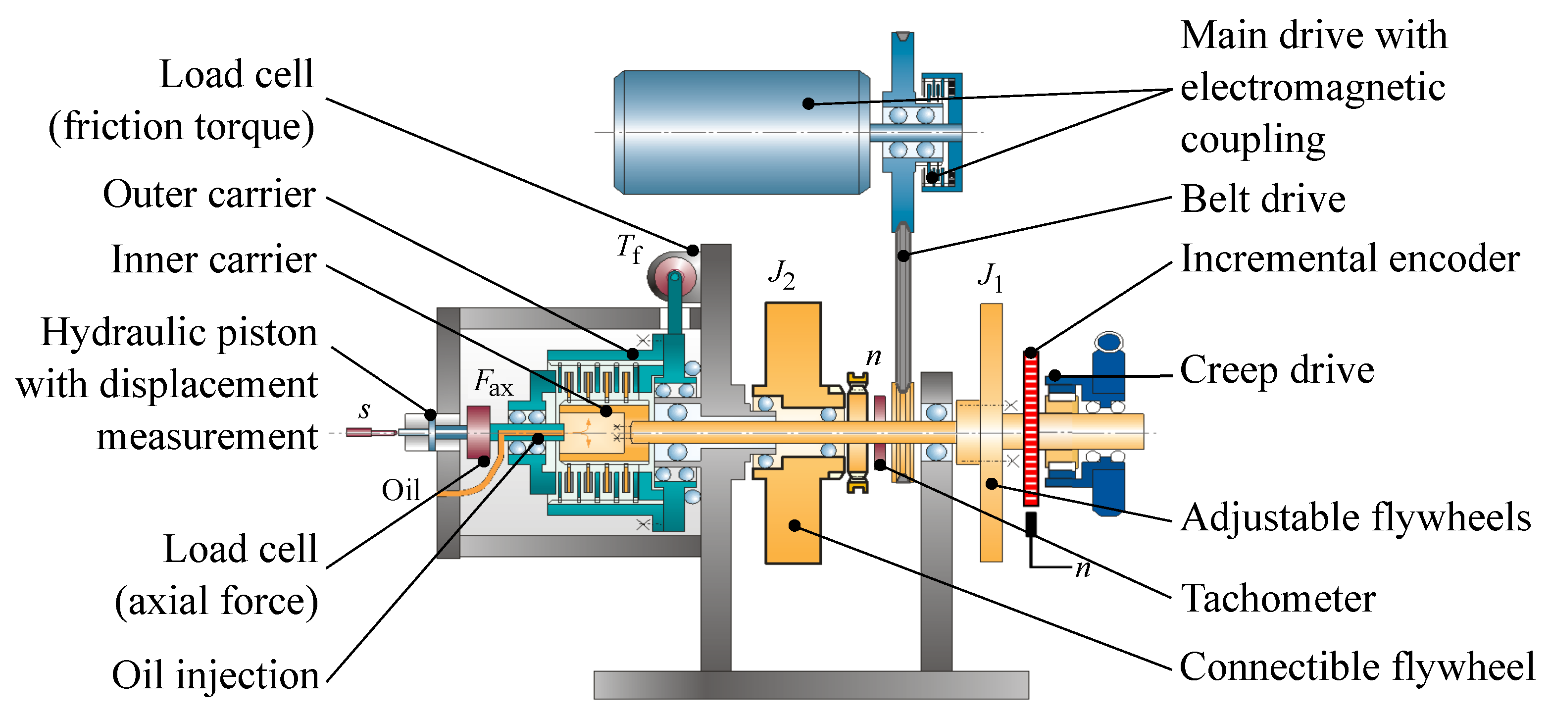
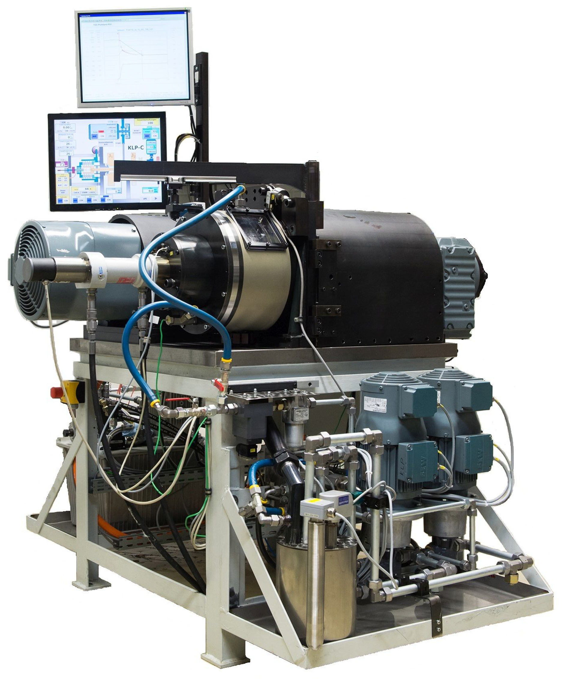
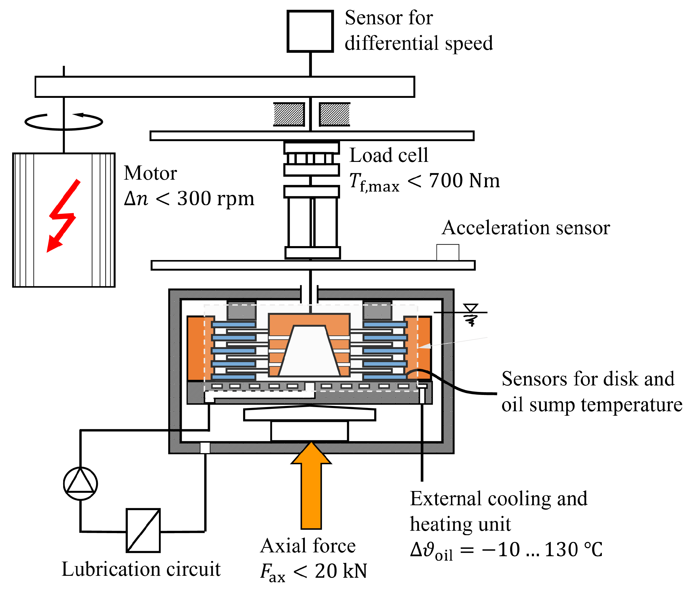
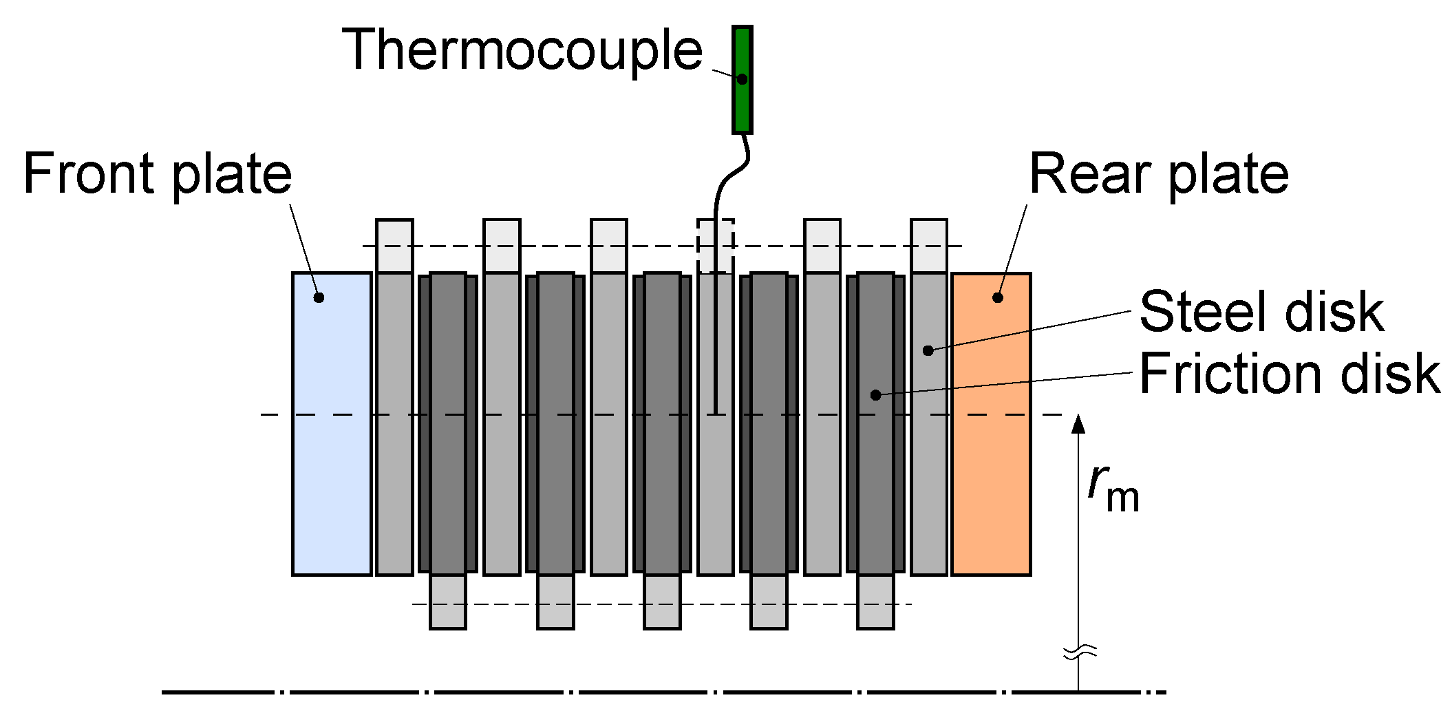
2.1. Test Setup
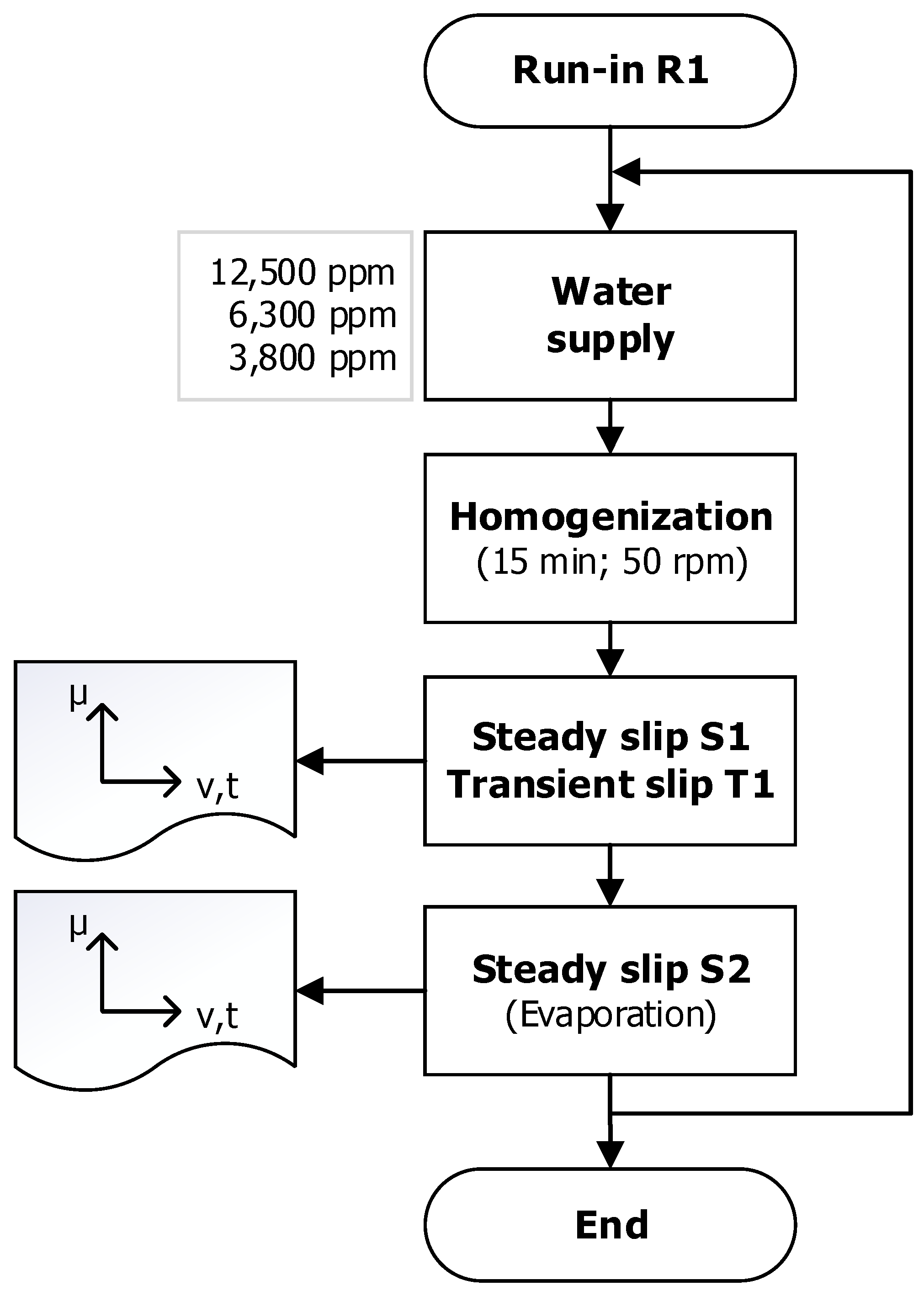
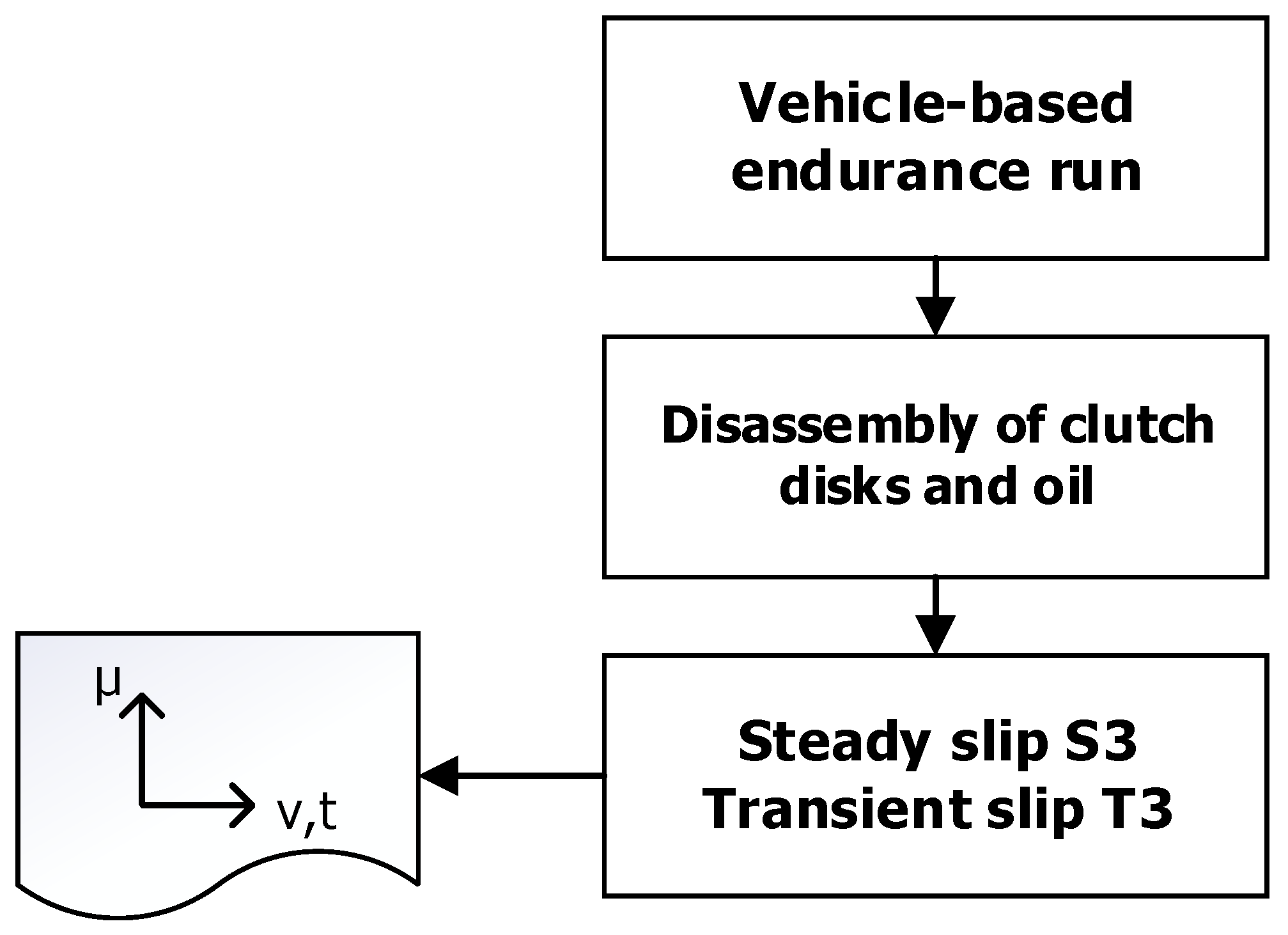
2.2. Operation Modes
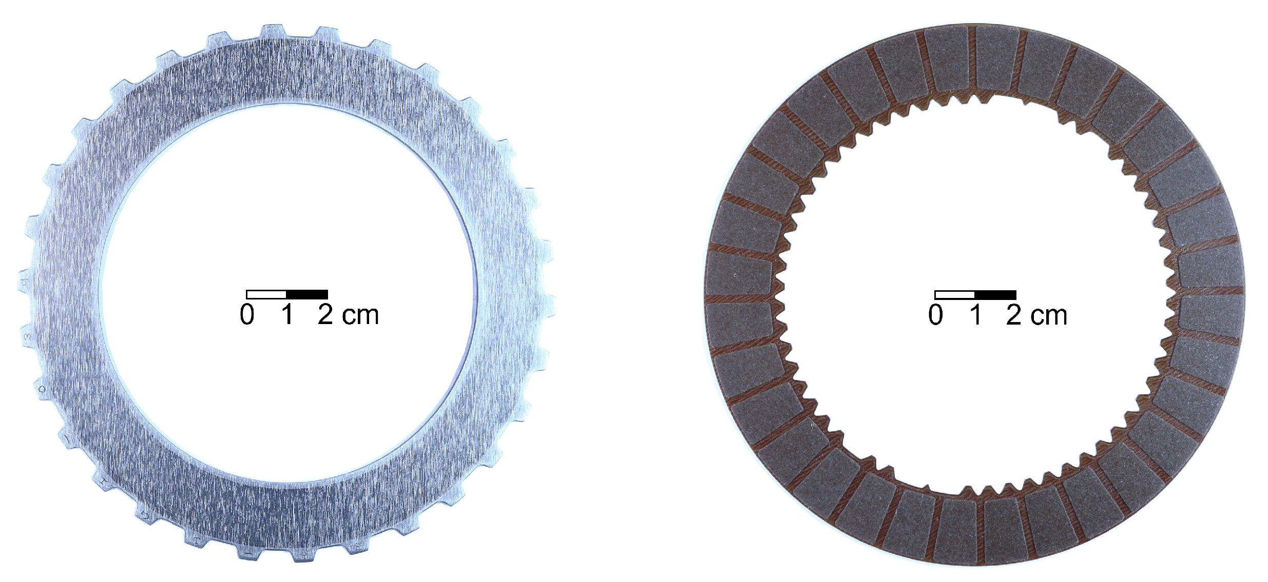
2.3. Materials
2.4. Test Procedure
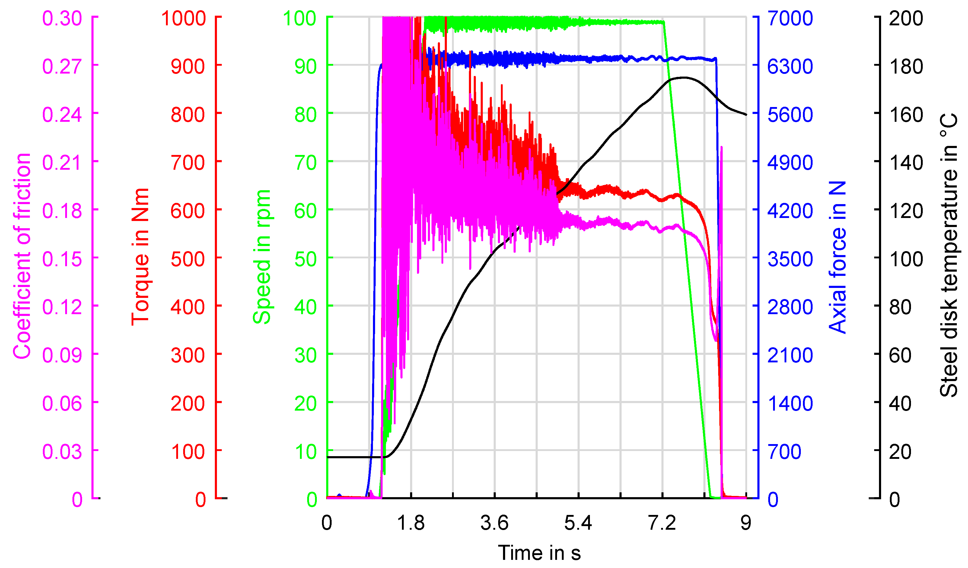
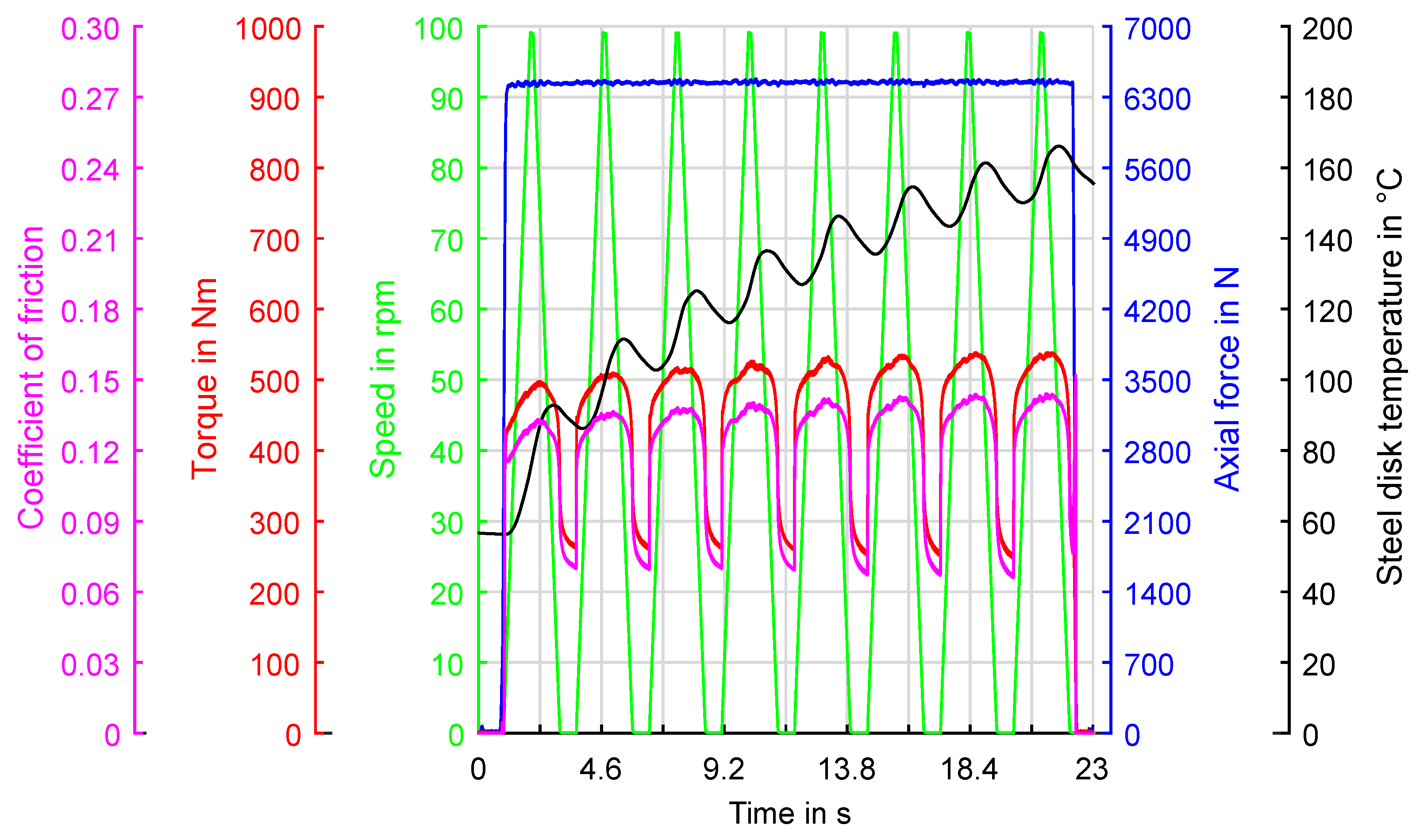
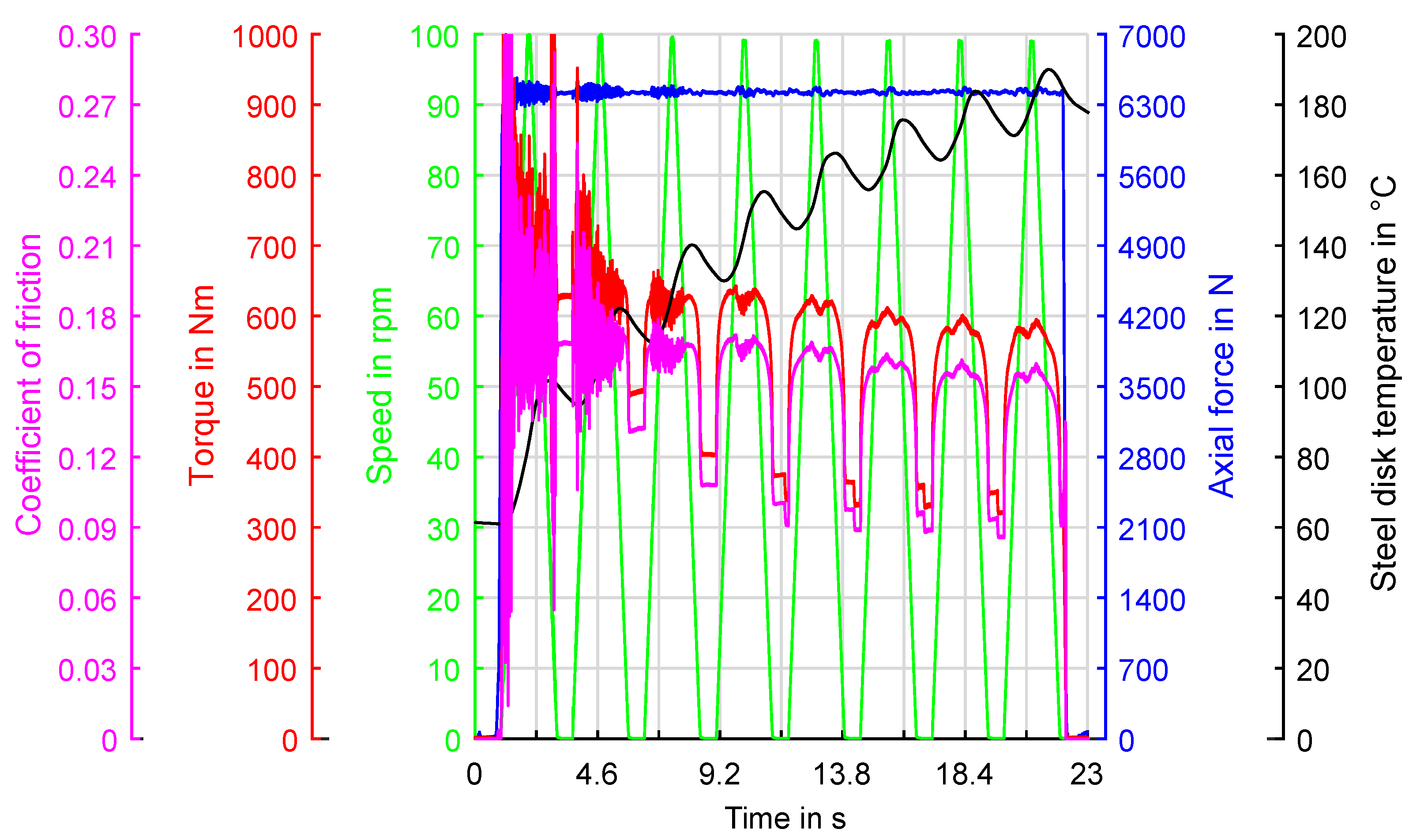
3. Results
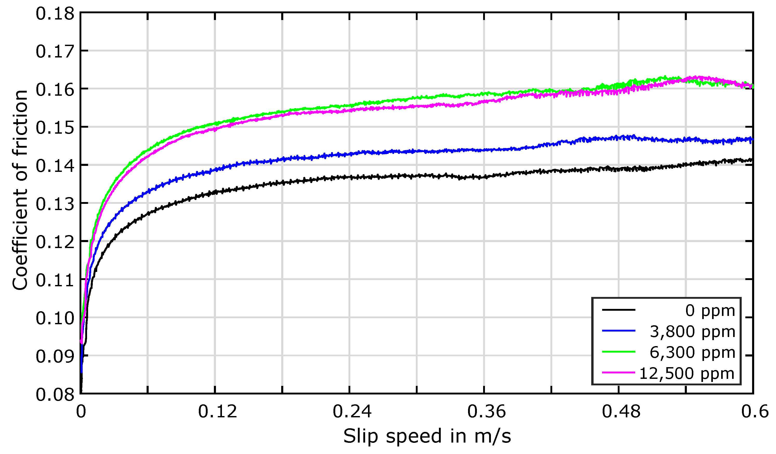
3.1. Effects of Water Contamination
3.2. Influence of Iron Particles and Energy Input
4. Discussion
5. Conclusions
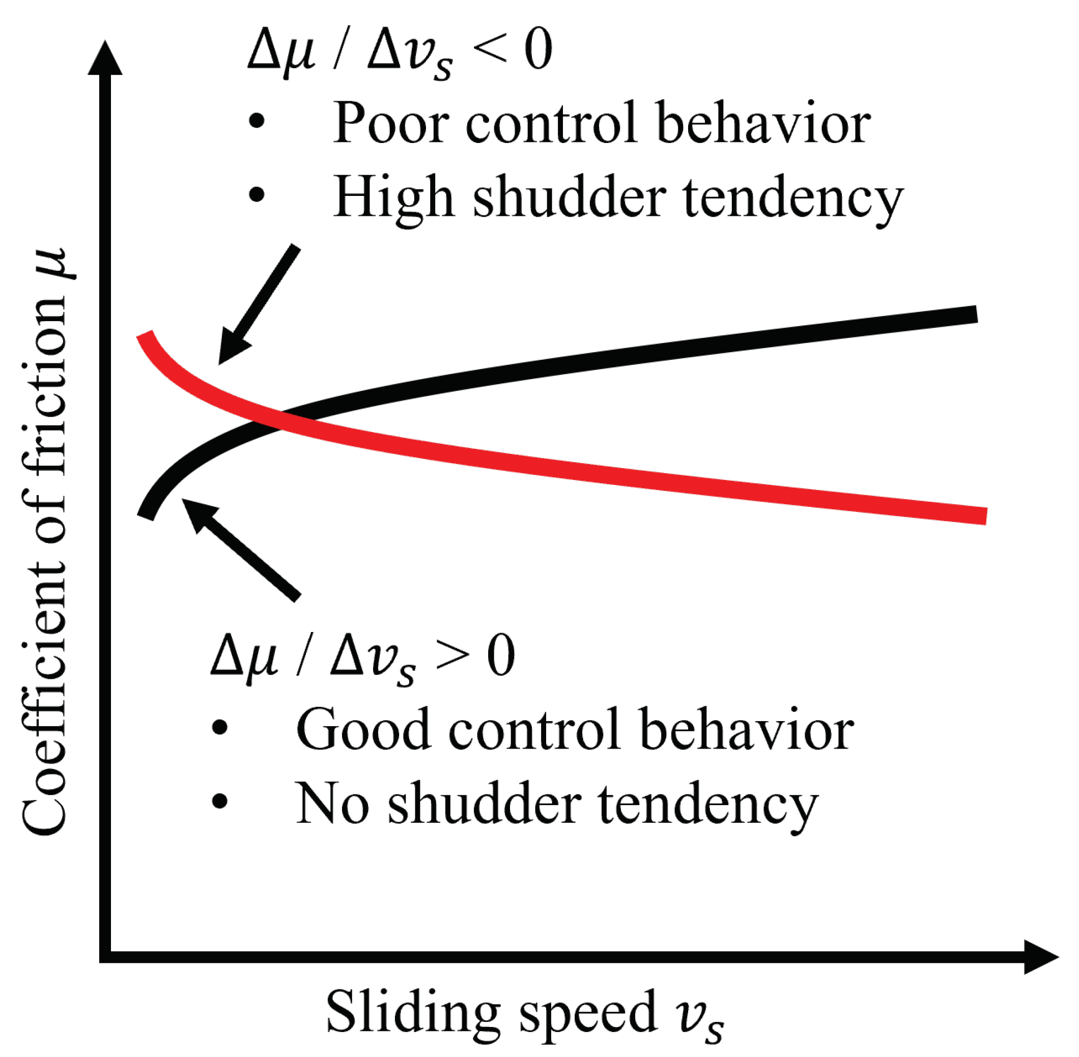
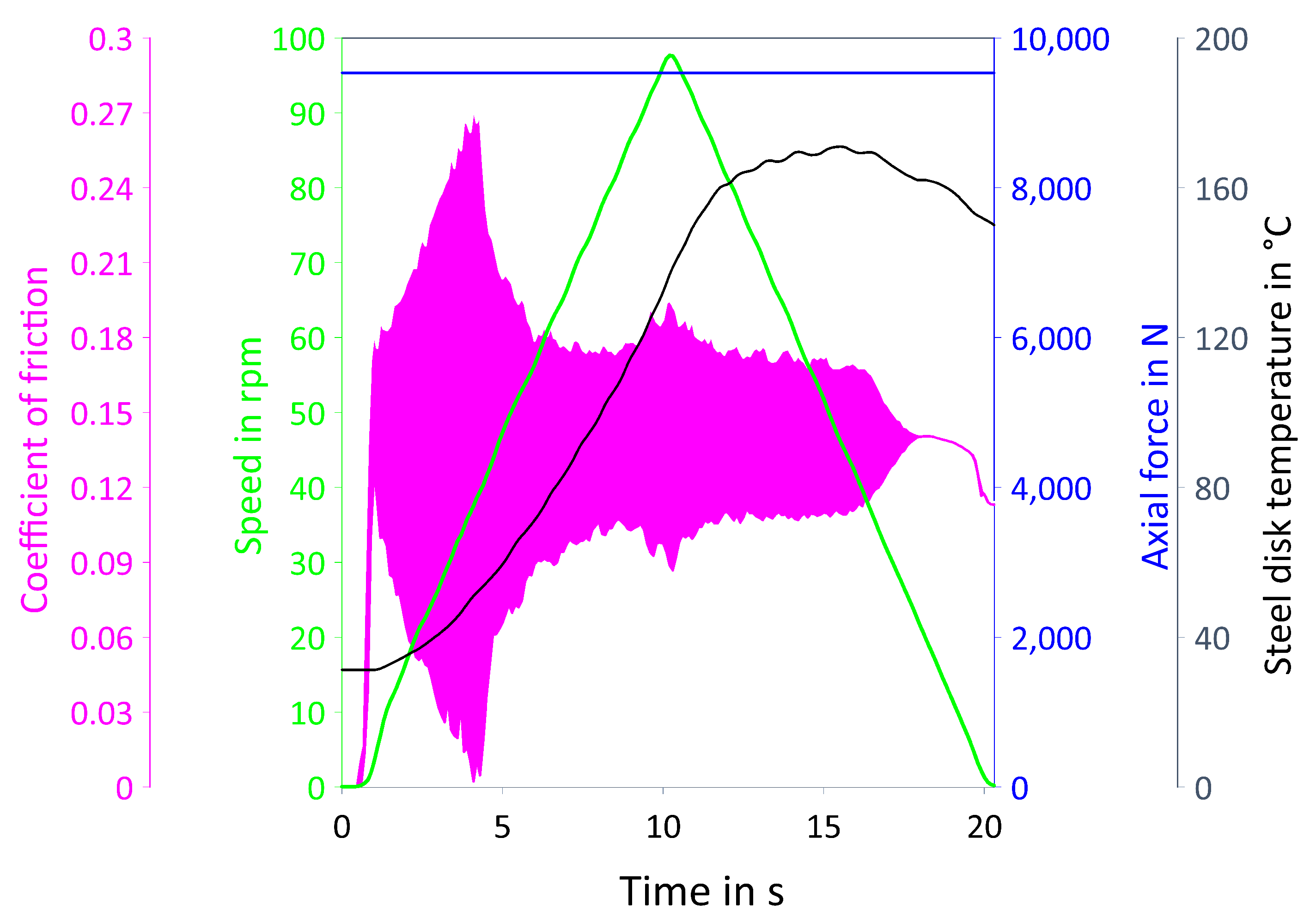
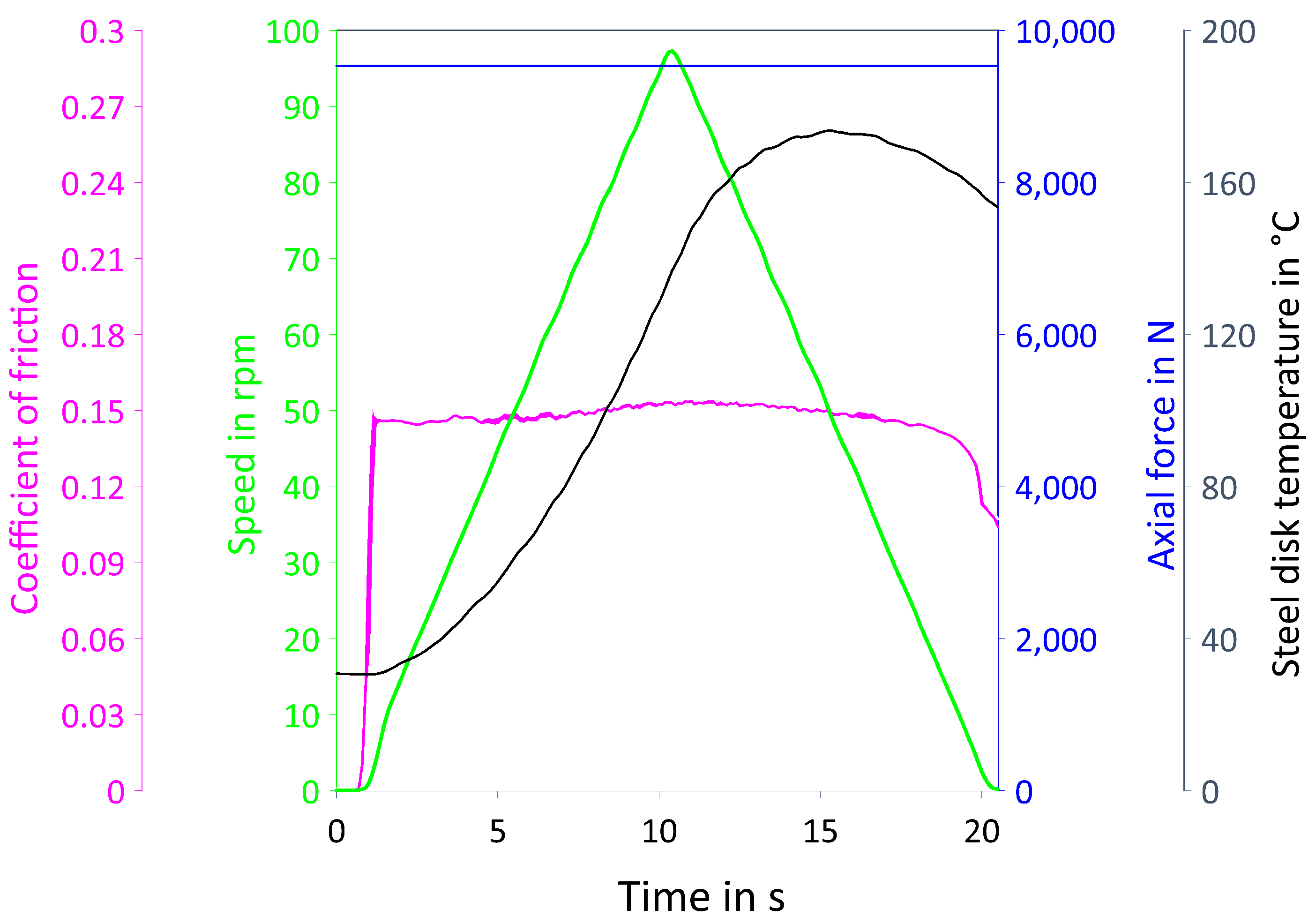
- Water as a contaminant inhibits additives in the lubricant from performing their intended function by building reverse micelles with additive molecules and adsorbing on the metallic surface of the steel plate [40].
- Thus, water addition leads to an instantaneous increase in the CoF. After evaporation, irreversible changes persist, as the CoF tends to be lower compared to an uncontaminated lubricant.
- Significantly high water levels tend to cause shudder behavior of the clutch, resulting in NVH issues or early-state damage of machine elements.
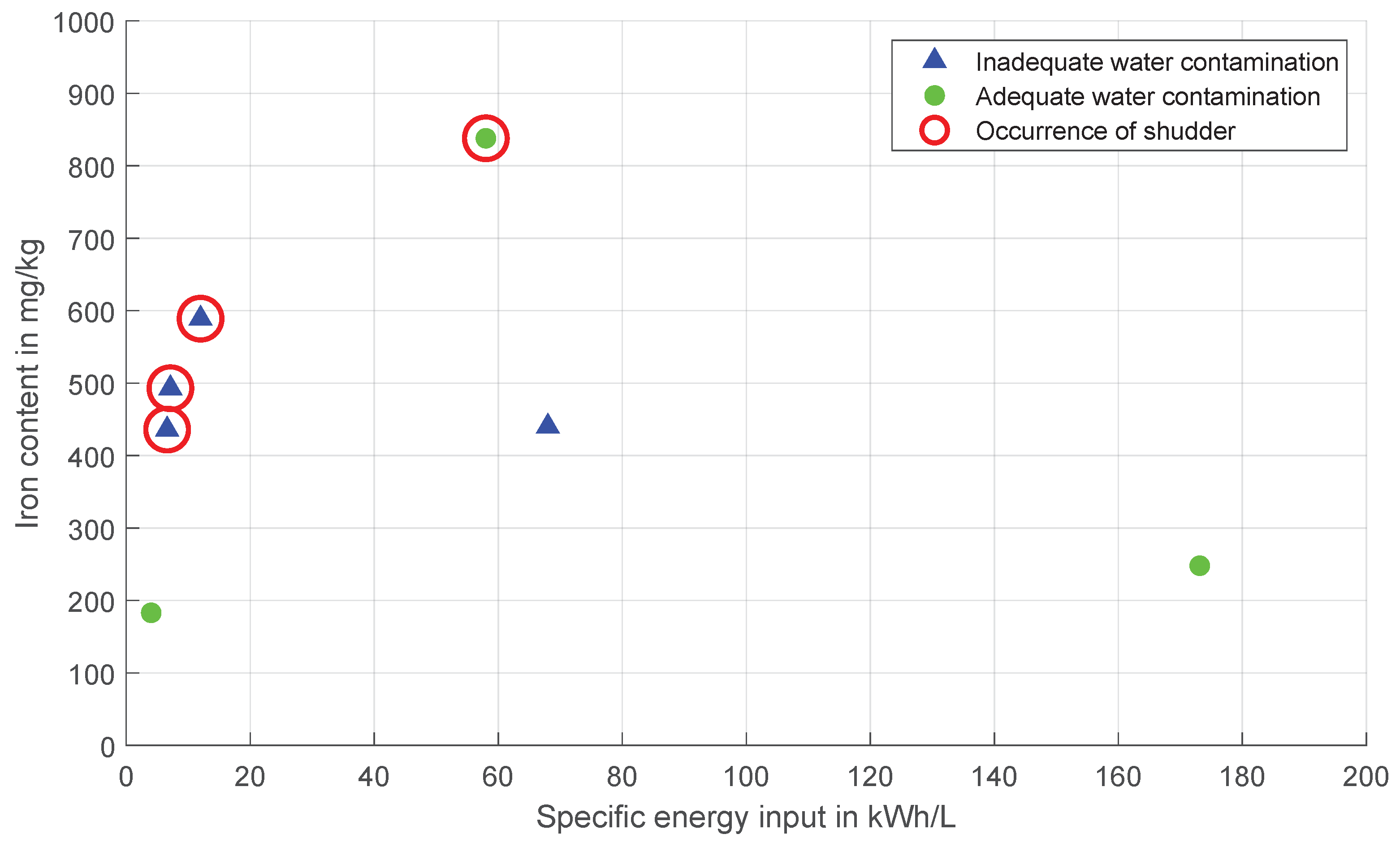
- Tests with oil samples out of vehicle-based endurance runs have underlined that iron particles, as well as their correlation to water contamination, contribute inherently to a performance loss of the lubricant. At the same time, the influence of the energy input is secondary.
Author Contributions
Funding
Institutional Review Board Statement
Informed Consent Statement
Data Availability Statement
Acknowledgments
Conflicts of Interest
Abbreviations
| CoF | Coefficient of friction |
| FM | Friction modifier |
| ICP-OES | Inductively coupled plasma optical emission spectrometry |
| KLP | Kupplungs–Lebensdauer–Pruefstand (clutch lifetime test rig) |
| NVH | Noise, vibration, harshness |
| PAO | Polyalphaolefin |
| R | Run-in shift |
| RMS | Root mean square |
| RRV | Ring-Reibungs-und-Verschleiss Tribometer (ring friction and wear test rig) |
| S | Steady slip shift |
| T | Transient slip shift |
References
- Baese, M.; Lebel, A.; Franz, R.; Prost, J. Analysis of Wet Vehicle Clutch Damage Mechanism caused by Water. Tribol. Schmier. 2022, 69, 7–13. [Google Scholar] [CrossRef]
- Bischofberger, A.; Ott, S.; Albers, A. Wet-Running Clutch as Actuator for Reduction of Oscillation in the Power Train—Influences of the Tribological System. Forsch. Ingenieurwesen 2020, 85, 1–10. [Google Scholar] [CrossRef]
- Naunheimer, H.; Bertsche, B.; Ryborz, J. Fahrzeuggetriebe: Grundlagen, Auswahl, Auslegung und Konstruktion, 3rd ed.; Springer Veiweg: Berlin, Germany, 2019. [Google Scholar]
- Hoehn, B.R.; Pflaum, H.; Mosbach, C. Methodik zur Beurteilung des Schmierstoffeinflusses auf das Reibschwingverhalten Nasslaufender Lamellenkupplungen; VDI Berichte: Dusseldorf, Germany, 2003; pp. 455–468. [Google Scholar]
- Neumueller, M. Einfluss der Oelalterung auf Reibungs- und Verschleissverhalten von Synchronisierungen. Ph.D. Thesis, Technical University of Munich, Munich, Germany, 2001. [Google Scholar]
- Mosbach, C. Das Reibungs- und Reibschwingverhalten Nasslaufender Lamellenkupplungen. Ph.D. Thesis, Technical University of Munich, Munich, Germany, 2002. [Google Scholar]
- Kugimiya, T.; Yoshimura, N.; Mitsui, J. Tribology of Automatic Transmission Fluid. Tribol. Lett. 1998, 5, 49–56. [Google Scholar] [CrossRef]
- Layher, M. Einfluss der Schmierstoffadditivierung auf das Reibungsverhalten Nasslaufender Reibschaltelemente. Ph.D. Thesis, Technische Universität München, München, Germany, 2011. [Google Scholar]
- Miyazaki, M.; Hoshino, M. Evaluation of Vibration-Preventive Properties of Lubricating Oils in Wet Friction Plates and Retation of Such Properties Using a Friction Tester; SAE Technical Paper No. 881674; SAE International: Warrendale, PA, USA, 1988; Volume 97, pp. 1061–1067. [Google Scholar] [CrossRef]
- Nakada, T.; Nomura, T.; Yoshioka, T.; Nonoyama, M. A Study of Additive Effects on ATF Frictional Properties Using New Test Methods; SAE Technical Paper No. 902150; SAE International: Warrendale, PA, USA, 1990. [Google Scholar] [CrossRef]
- Ohtani, H.; Hartley, R.J.; Stinnett, D.W. Prediction of Anti-Shudder Properties of Automatic Transmission Fluids Using a Modified SAE No. 2 Machine. SAE Trans. 1994, 103, 456–467. [Google Scholar]
- Maeki, R.; Nyman, P.; Olsson, R.; Ganemi, B. Measurement and Characterization of Anti-Shudder Properties in Wet Clutch Applications; SAE Technical Paper No. 2005-01-0878; SAE International: Warrendale, PA, USA, 2005. [Google Scholar] [CrossRef]
- Zhao, H.; Morina, A.; Neville, A.; Vickerman, R. Anti-Shudder Properties of ATFs—Investigation into Tribofilm Composition on Clutch Friction Material and Steel Surfaces and the Link to Frictional Performance. Tribol. Trans. 2012, 55, 782–797. [Google Scholar] [CrossRef]
- Hauser, C. Einfluss der Oelalterung auf Reibcharakteristik und Reibschwingverhalten von Lamellenkupplungen. Ph.D. Thesis, Technical University of Munich, Munich, Germany, 2006. [Google Scholar]
- Bischofberger, A.; Ott, S.; Albers, A. Influence of Operating Parameters on the Vibration Reduction Effect in the Wet-Running Clutch System. Forsch. Ingenieurwesen 2021, 85, 933–944. [Google Scholar] [CrossRef]
- Fatima, N.; Marklund, P.; Larsson, R. Water Contamination Effect in Wet Clutch System. Proc. Inst. Mech. Eng. Part D J. Automob. Eng. 2013, 227, 376–389. [Google Scholar] [CrossRef]
- Fatima, N. Impact of Water Contamination and System Design on Wet Clutch Tribological Performance. Ph.D. Thesis, Lulea University of Technology, Lulea, Sweden, 2014. [Google Scholar]
- Wang, H. Effects of Water in All-Wheel-Drive Clutch Oil on All-Wheel-Drive Cornering Noise; SAE Technical Paper No. 2022-01-5103; SAE International: Warrendale, PA, USA, 2022. [Google Scholar] [CrossRef]
- Akita, Y.; Abe, K.; Osawa, Y.; Goto, Y.; Nagasawa, Y.; Sugiura, N.; Wakamatsu, S.; Kosaka, K. Analysis of Friction Coefficient Variation with Moisture between Friction Surfaces; SAE Technical Paper No. 2016-01-0411; SAE International: Warrendale, PA, USA, 2016. [Google Scholar] [CrossRef]
- Williamson, W.; Rhodillegible, B. The Effects of Water on Cellulose-Based Frictional Surfaces in Automatic Transmission Clutch Plates; SAE Technical Paper 961917; SAE International: Warrendale, PA, USA, 1996. [Google Scholar] [CrossRef]
- Baese, M.; Heipl, O.; Cokdogru, I.; Lipinsky, D.; Mallach, D.; Franz, R. Analysis of Wet Clutch Wear Mechanism with Tribological Tests and Time of Flight Secondary Mass Spectroscopy (ToF-SIMS). Forsch. Ingenieurwesen 2019, 83, 247–258. [Google Scholar] [CrossRef]
- Fatima, N.; Marklund, P.; Mathew, A.P.; Larsson, R. Wet Clutch Friction Interfaces under Water-Contaminated Lubricant Conditions. Tribol. Trans. 2016, 59, 441–450. [Google Scholar] [CrossRef]
- Engelhardt, C.M. Einfluss von Wasser in Getriebeoelen auf die Zahnflankentragfaehigkeit Einsatzgehaerteter Stirnraeder. Ph.D. Thesis, Technical University of Munich, Munich, Germany, 2019. [Google Scholar]
- Barthel, A.J.; Al-Azizi, A.; Kim, S.H. Fundamental Understanding of Environmental Effects on Adhesion and Friction: Alcohol and Water Adsorption Cases. Tribol. Lett. 2013, 50, 157–168. [Google Scholar] [CrossRef]
- Dorgham, A.; Azam, A.; Parsaeian, P.; Wang, C.; Morina, A.; Neville, A. An Assessment of the Effect of Relative Humidity on the Decomposition of the ZDDP Antiwear Additive. Tribol. Lett. 2021, 69, 72. [Google Scholar] [CrossRef]
- SAE No. 2 Clutch Friction Test Machine Guidelines; SAE International: Warrendale, PA, USA, 2012.
- Fernandes, G.; Zanotto, P.; Sinatora, A. The Role of Counter-Face Roughness on the Tribological Performance of a Clutch System Tested with a Pin-On-Disc Tribometer. Lubricants 2016, 4, 18. [Google Scholar] [CrossRef]
- Meingaßner, G.J.; Pflaum, H.; Stahl, K. Test-Rig Based Evaluation of Performance Data of Wet Disk Clutches. In Proceedings of the 14th International CTI Symposium, Berlin, Germany, 7–10 December 2015; pp. 1–11. [Google Scholar]
- Strobl, P.; Schermer, E.; Groetsch, D.; Pointner-Gabriel, L.; Voelkel, K.; Pflaum, H.; Stahl, K. Identification and Validation of Linear Friction Models Using ANOVA and Stepwise Regression. Lubricants 2022, 10, 286. [Google Scholar] [CrossRef]
- Baumgartner, A. Reibungsverhalten Nasslaufender Lamellenkupplungen—Messunsicherheiten und Auswertemethoden. Master’s Thesis, Technical University of Munich, Munich, Germany, 2020. [Google Scholar]
- Shui, H.; Zhang, Y.; Yang, H.; Upadhyay, D.; Fujii, Y. Machine Learning Approach for Constructing Wet Clutch Torque Transfer Function. SAE Int. J. Adv. Curr. Pract. Mobil. 2021, 3, 2738–2744. [Google Scholar] [CrossRef]
- Berger, E.J.; Sadeghi, F.; Krousgrill, C.M. Finite Element Modeling of Engagement of Rough and Grooved Wet Clutches. J. Tribol. 1996, 118, 137–146. [Google Scholar] [CrossRef]
- Berger, E.J.; Sadeghi, F.; Krousgrill, C.M. Analytical and Numerical Modeling of Engagement of Rough, Permeable, Grooved Wet Clutches. J. Tribol. 1997, 119, 143. [Google Scholar] [CrossRef]
- Gao, H.; Barber, G.C.; Shillor, M. Numerical Simulation of Engagement of a Wet Clutch with Skewed Surface Roughness. J. Tribol. 2002, 124, 305–312. [Google Scholar] [CrossRef]
- Gao, H.; Barber, G.C. Microcontact Model for Paper-Based Wet Friction Materials. J. Tribol. 2002, 124, 414–419. [Google Scholar] [CrossRef]
- Kimura, Y.; Otani, C. Contact and Wear of Paper-Based Friction Materials for Oil-Immersed Clutches—Wear Model for Composite Materials. Tribol. Int. 2005, 29, 943–950. [Google Scholar] [CrossRef]
- Crawford, J.; Psaila, A. Miscellaneous Additives. In Chemistry and Technology of Lubricants; Mortier, R.M., Orszulik, S.T., Eds.; Springer Science+Business Media: Berlin/Heidelberg, Germany, 1994; Volume 1, pp. 160–173. [Google Scholar]
- Dorgham, A.; Azam, A.; Parsaeian, P.; Khan, T.; Sleiman, M.; Wang, C.; Morina, A.; Neville, A. Understanding the Effect of Water on the Transient Decomposition of Zinc Dialkyldithiophosphate (ZDDP). Tribol. Int. 2021, 157, 106855. [Google Scholar] [CrossRef]
- Fatima, N.; Holmgren, A.; Marklund, P.; Minami, I.; Larsson, R. Degradation Mechanism of Automatic Transmission Fluid by Water as a Contaminant. Proc. Inst. Mech. Eng. Part D J. Automob. Eng. 2015, 229, 74–85. [Google Scholar] [CrossRef]
- Colyer, C.C.; Gergel, W.C. Detergants/Dispersants. In Chemistry and Technology of Lubricants; Mortier, R.M., Orszulik, S.T., Eds.; Springer Science+Business Media: Berlin/Heidelberg, Germany, 1994; Volume 1, pp. 62–82. [Google Scholar]


| Parameter | Value | |
|---|---|---|
| General | Maximum axial force | |
| Disk dimensions | ||
| Oil temperature | ||
| Oil flow rate | ||
| Oil pressure | ||
| Variable inertia | ||
| Basic inertia | ||
| Creep drive | Slip speed | |
| Max. torque | ||
| Main drive | Slip speed | |
| Max. torque |
| Parameter | Measurement Uncertainty |
|---|---|
| Axial force | ± |
| Torque | ± |
| CoF | ± |
| Slip speed (main drive) | ± |
| Slip speed (creep drive) | ± |
| Lubricant | Kinematic Viscosity at C | Kinematic Viscosity at C |
|---|---|---|
| L-204 |
| Lubricant | Ca | Mg | B | P | S |
|---|---|---|---|---|---|
| L-204 |
| Name | Test Rig | Pressure p | Differential Speed | Number of Slip Phases | Iterations |
|---|---|---|---|---|---|
| R1 | KLP-260 | 1 | 100 | ||
| S1 | KLP-260 | 1 | 10 | ||
| T1 | KLP-260 | 8 | 10 | ||
| S2 | KLP-260 | 1 | 90 | ||
| S3 | RRV | 1 | 3 | ||
| T3 | RRV | 1 | 3 |
| Sample Number | Water Contamination | Specific Energy Input | Iron Content | CoF at and | Occurrence of Shudder |
|---|---|---|---|---|---|
| 1 | inadequate | no shudder | |||
| 2 | inadequate | shudder | |||
| 3 | inadequate | shudder | |||
| 4 | inadequate | shudder | |||
| 5 | adequate | no shudder | |||
| 6 | adequate | no shudder | |||
| 7 | adequate | shudder |
Disclaimer/Publisher’s Note: The statements, opinions and data contained in all publications are solely those of the individual author(s) and contributor(s) and not of MDPI and/or the editor(s). MDPI and/or the editor(s) disclaim responsibility for any injury to people or property resulting from any ideas, methods, instructions or products referred to in the content. |
© 2023 by the authors. Licensee MDPI, Basel, Switzerland. This article is an open access article distributed under the terms and conditions of the Creative Commons Attribution (CC BY) license (https://creativecommons.org/licenses/by/4.0/).
Share and Cite
Wirkner, J.; Baese, M.; Lebel, A.; Pflaum, H.; Voelkel, K.; Pointner-Gabriel, L.; Besser, C.; Schneider, T.; Stahl, K. Influence of Water Contamination, Iron Particles, and Energy Input on the NVH Behavior of Wet Clutches. Lubricants 2023, 11, 459. https://doi.org/10.3390/lubricants11110459
Wirkner J, Baese M, Lebel A, Pflaum H, Voelkel K, Pointner-Gabriel L, Besser C, Schneider T, Stahl K. Influence of Water Contamination, Iron Particles, and Energy Input on the NVH Behavior of Wet Clutches. Lubricants. 2023; 11(11):459. https://doi.org/10.3390/lubricants11110459
Chicago/Turabian StyleWirkner, Johannes, Mirjam Baese, Astrid Lebel, Hermann Pflaum, Katharina Voelkel, Lukas Pointner-Gabriel, Charlotte Besser, Thomas Schneider, and Karsten Stahl. 2023. "Influence of Water Contamination, Iron Particles, and Energy Input on the NVH Behavior of Wet Clutches" Lubricants 11, no. 11: 459. https://doi.org/10.3390/lubricants11110459
APA StyleWirkner, J., Baese, M., Lebel, A., Pflaum, H., Voelkel, K., Pointner-Gabriel, L., Besser, C., Schneider, T., & Stahl, K. (2023). Influence of Water Contamination, Iron Particles, and Energy Input on the NVH Behavior of Wet Clutches. Lubricants, 11(11), 459. https://doi.org/10.3390/lubricants11110459