Article

Effects of Oil Supply Condition on Spinning–Sliding EHL

1
School of Mechanical & Automotive Engineering, Qingdao University of Technology, Qingdao 266520, China
2
School of Mechanical Engineering, University of Leeds, Leeds LS2 9JT, UK
*
Author to whom correspondence should be addressed.
Lubricants 2023, 11(10), 451; https://doi.org/10.3390/lubricants11100451
Submission received: 12 September 2023 / Revised: 13 October 2023 / Accepted: 16 October 2023 / Published: 19 October 2023
(This article belongs to the Special Issue Friction and Wear of Rolling-Element Bearings)

Abstract

:
An optical interference test rig with spinning elastohydrodynamic lubrication (EHL) was established to investigate the spinning lubrication performance under different oil-supply conditions. Variations in the shape and thickness of the film versus the velocity, the load, and the spinning factor under fully flooded lubrication were discussed, and the effects of the inlet-starvation position and oil-supply quantity were analyzed. The results show that the symmetry for the classical horseshoe shape does not exist under both spinning–rolling and spinning–sliding EHL conditions. Different from spinning–rolling, a dimple is generated more easily under the spinning–sliding condition. The dimple is related to the load and the speed. The effects of the inlet-starvation position on spinning EHL are different. When the inlet starvation is on the low-speed side of the contact, that is, proximal to the center of rotation, the inlet-starvation position extends from the proximal side to the center of rotation to the distal side to the center of rotation, i.e., the high-speed side of the contact, which is starved easily. When the starvation happens on the high-speed side, i.e., distal to the center of rotation, the starvation at this position becomes much more severe, and lubrication failure and a risk of wear will occur. In addition, the effects of oil-supply quantity on spinning EHL are important.

1. Introduction

Elastohydrodynamic lubrication (EHL) mainly studies pure-rolling (i.e., the slide–roll ratio, defined as the ratio of rolling to sliding velocity is 0), slide–rolling, or simple-sliding (i.e., the slide-to-roll ratio is 2.0) conditions between two contact solids [1,2,3,4]). However, the spinning motion, which is the rotation of the roller about its contact normal line, also exists in angular contact ball bearings due to the existence of the contact angle, defined as the angle between the normal line of the ball-to-raceway contact point and the radial direction of the rolling bearing. The failure caused by the spinning motion is common in aero-engine, main-shaft bearings under high-speed conditions [5].
The investigation into the effects of the spinning motion on the tribological performance of bearings began in the 1960s. A test rig for measuring the frictional moment in the case of spinning was developed by the National Aeronautics and Space Administration(NASA) Lewis Research Center in 1965 [6]. Parker et al. [7] and Dietrich et al. [8] carried out an experiment and concluded that the traction coefficient under the spinning condition was larger than that in the simple-sliding condition. Allen et al. [9] presented an EHL solution for the spinning torque of a ball spinning without rolling in a non-conforming groove and predicted an increase in torque with increasing stress and spinning speed. Therefore, the spinning motion is very important to consider in engineering practice.
Thorp and Gohar [10] measured the lubricant film shape of the EHL problems, considering the spinning rotation (termed “spinning EHL” in this paper), using the optical interference technique. Johnson and Roberts [11] analyzed the rheological property of the lubricant with spinning. Dowson et al. [12] investigated spinning EHL, and their numerical solution was consistent with experimental results [13]. With extremely low velocity, Jiang et al. [14] and Li et al. [15] investigated the performance of spinning–sliding and spinning–rolling EHL with an optical interference technique, respectively. Dormois et al. [16] presented a study of the spinning influence on film thickness and friction in EHL circular contacts under isothermal and fully flooded conditions. Based on the structural analysis of the inner rib and the large end of the roller and considering the spin–slide effects between the rib and the large end of the roller, a thermal elastohydrodynamic lubrication model with a Carreau rheological model was established in a tapered roller bearing [17].
In comparison with fully flooded lubrication, starvation refers to an inadequate lubricant supply at the inlet’s conjunction [18]. The assumption of fully flooded lubrication does not reflect the actual conditions of the contact in roller bearings, especially of large dimensions and higher oil viscosity. Moreover, in a complete bearing, the lubrication condition of each contact determines the oil supply available for the subsequent one. This implies that the roller-end/flange contact may operate under a starved condition. The starved EHL problems of elliptical contact between the riband and the roller end in tapered roller bearings have been solved numerically in which rolling speeds with additional sliding and spin are considered [19], and it is concluded that friction forces and moments are highly dependent on the inlet oil amount, the bearing speed, and the load. Very recently, Vazquez [20,21] investigated large-size spinning contacts located at the interface between the roller end and the flange in rolling-element bearings, evaluated the influence of lubricant starvation on the film thickness distribution of the contact, and analyzed how spinning might affect this mechanism. However, no dimple was observed in the experimental results due to the lower oil viscosity.
For the roller-end/flange contact [22,23,24,25,26], a spin motion would assist the inlet replenishment process by periodically bringing the oil left from the race side bands or the roller surface. Therefore, further research on spinning combined with the oil-starvation problem needs to be carried out in sliding EHL and the influence of the oil supply condition with slightly higher oil viscosity. The main goal of this study is to evaluate the influence of the oil-supply condition on spinning EHL and analyze how spinning might affect this oil-starvation mechanism.

2. Experimental Device and Methods

2.1. Test Rig

Based on the optical interferometry technique [27], a test rig, shown in Figure 1, was established to investigate spinning EHL. A glass disk (component 3 in Figure 1) was driven by a synchronous pulley (component 2 in Figure 1). A steel ball (component 4 in Figure 1) was loaded against the glass disk with a normal load w. A skew unit (component 5 in Figure 1) was used to adjust the position of the ball axis, and the XY table (component 6 in Figure 1) was employed to determine the offset r. Point O′ is the rotational center of the disk, and r is the offset distance between O′ and the contact center O. If r = 0, the schematic describes a pure spinning problem. When r > 0, the spinning can be realized by adjusting the XY table numbered 6 as shown in Figure 1.
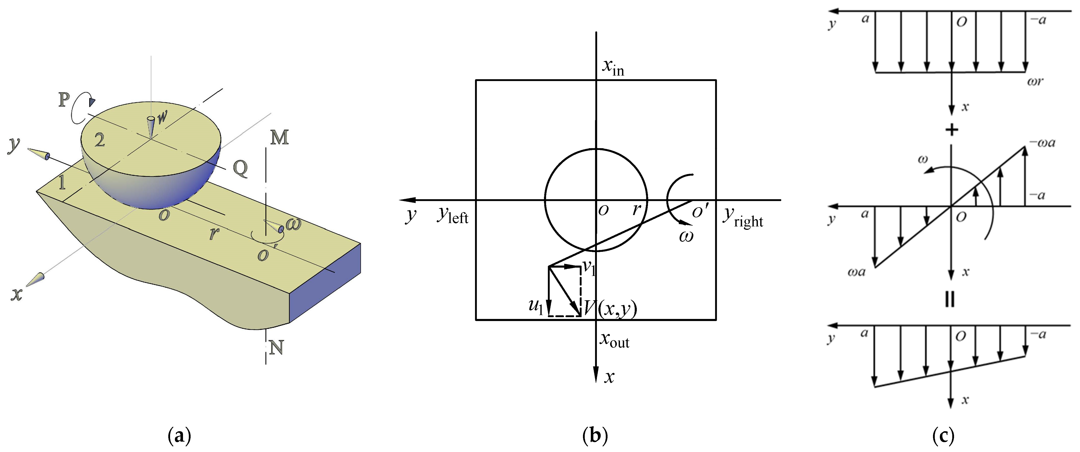
Figure 2a shows the schematic of a point-contact, spinning EHL problem in which a disk, defined as plane 1, rotates around its axis MN with an angular speed ω, and a steel ball can rotate around its axis PQ. If the steel ball rotates, it is a spinning–rolling problem because the spinning and rolling motion co-exist; if the steel ball is stationary, it becomes a spinning–sliding problem because there are spinning and sliding motions simultaneously. The variation in the velocity direction of the steel ball can be achieved by adjusting the skew unit horizontally in Figure 1 for the spinning–rolling condition. a is the Hertzian contact radius. From Figure 2b, when r is infinity, this is a simple-slide problem. When the contact center coincides with the center of rotation (r = 0), it becomes a pure-spin problem. When the contact center deviates from the center of rotation (r > 0), the slide and spin coexist, and it is called spinning–sliding.

2.2. Experimental Material and Condition

The properties of the polybutene oil used in the experiment (PB950) are listed in Table 1. The disk is made of BK7 glass and coated with a semi-reflecting chromium film on the loaded side of the disk as a beam-splitter. The diameter of the steel ball is 25.4 mm. The Ra values of the chromium film and the steel ball are 7 and 5 nanometers, respectively, which are measured with Form Talysurf PGI 800 manufactured by TAYLOR HOBSON LIMITED, Leicester, UK. The reduced modulus of elasticity between the steel ball and the glass disk is 117 GPa.
Ambient temperature, measured with a thermometer, remains at 18 ± 1 °C, and the relative humidity is at 50 ± 5%. In order to realize fully flooded and starved lubrication, different oil-supply quantities are selected during the experiments. The different oil-supply conditions are achieved using a dropper with an oil volume of 0.1 mL. The fully flooded condition requires more than 0. 03 mL of oil, while the oil-starvation conditions require initially placing 1/3 of the oil volume at the contact point O and then distributing the remaining 2/3 of the oil volume on one side to obtain different inlet-starvation positions.

2.3. Loading and Velocities

The maximum Hertzian pressure pH is 0.357, 0.393, 0.424, 0.495, 0.534, and 0.548 GPa, corresponding to the load w of 11.1, 14.8, 18.5, 29.6, 37.0, and 40 N in the experiment.
Figure 2b shows the velocity analysis of this spinning EHL contact. The velocity of an arbitrary point on plane 1 (shown in Figure 2a) along the x and y directions can be written as
{ u 1 ( x , y ) = ω ( r + y ) v 1 ( x , y ) = ω x
Figure 2c shows the velocity analysis for the spinning–sliding condition, i.e., the ball is stationary, where the top is for velocity without spinning, the middle is for velocity due to the spinning motion, and the bottom is the overall velocity. So, the overall velocity along the x-axis is composed of the disk velocity at the contact center, ur = v = ωr, and the velocity from the spin motion, us = ωa. The spinning factor can be defined as the ratio of us to ur:
S sp = a / r
The disk velocity at the Hertzian contact boundary on the y-axis is given by
{ u 1 L = ω ( r + a ) u 1 R = ω ( r a )
From Equation (3), the disk velocity u1 on the two sides of the contact region on the y-axis is asymmetric, and the velocity proximal to the center of rotation of the disc is lower, so the film at this side will be thinner.
When the ball is stationary, the entrainment velocities (the mean velocity of the ball and the disk) of the lubricant along the x direction at the contact point is uR = v/2 = ωr/2.
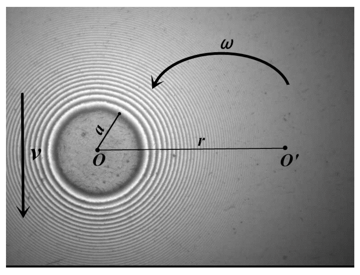
For the interferometry images shown in Figure 3, the contact zone is circular, the Hertzian contact radius is defined as a, and v is the disk velocity at the contact point. The velocity distal to the center of rotation is u1L, and the velocity proximal to the center of rotation is u1R.

3. Results

3.1. Preliminary Results of Measurement

To show the accuracy on normal force, comparisons of the Hertzian contact radius between the theory and experiment are given in Table 2. It can be found that the theoretical and experimental Hertzian contact radii are identical.
Interference images of the oil at the spinning–sliding and spinning–rolling EHL status, respectively, are shown in Figure 4 for w = 40 N (the maximum Hertzian pressure is 0.548 GPa, the load parameter W = w/E′/Rx/Rx =2.1 × 10⁻⁶), Ssp = 0.1, and v = 0.0188 m/s (at the contact center, the entrainment velocity uR = 0.0094 m/s). It can be observed clearly that the film shape is asymmetric because of the spinning motion, and the thinner film appears in the contact region.
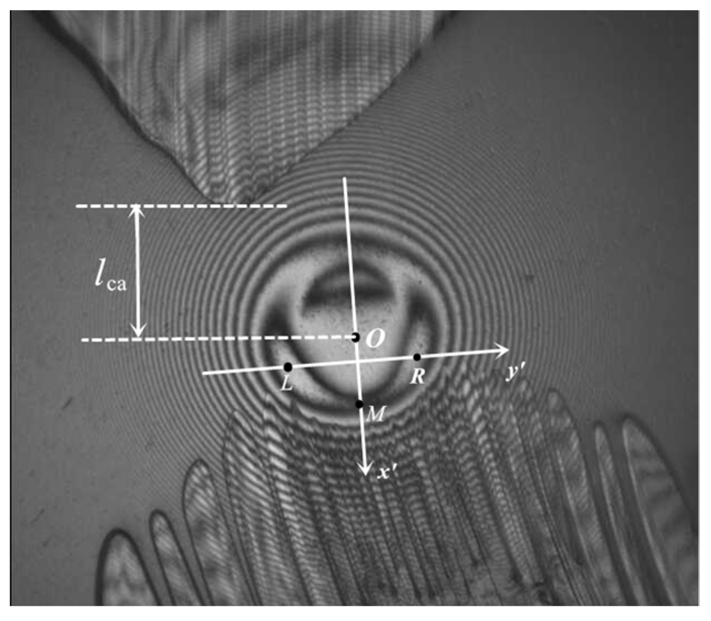
Note that the results in Section 3.2, Section 3.3, Section 3.4 and Section 3.5 are for spinning–sliding EHL. Figure 5 illustrates the information to describe the results for the spinning interferometry pattern, where the x′ axis goes through the contact center O and the position of the minimum film thickness M, and the y′ axis is perpendicular to the x′ axis and points to the rotational center O′. The points L and R are the minimum film thickness distal and proximal to the center of rotation, respectively. Moreover, y′ is passing through the minimum film thickness locations L and R. lca is the distance from the inlet meniscus to the contact center. The meniscus is a boundary that inhibits the generation of pressure and, consequently, the film thickness build up. The position of the air–oil meniscus, located upstream (inlet) of the contact region, was taken as an indicator of the degree of starvation: the closer the lubricant boundary was to the Hertzian contact region, the thinner the film thickness was expected to be throughout said area, and the shape of the meniscus resembles a parabola.
The inlet dimple is a film shape feature, which refers to a small dimple at the inlet. Horseshoe is a conventional point-contact EHL film shape, featuring a constant film thickness in the central region bounded by two side lobes and a film constriction at the outlet.

3.2. Effects of Speed and Load under Fully Flooded Condition

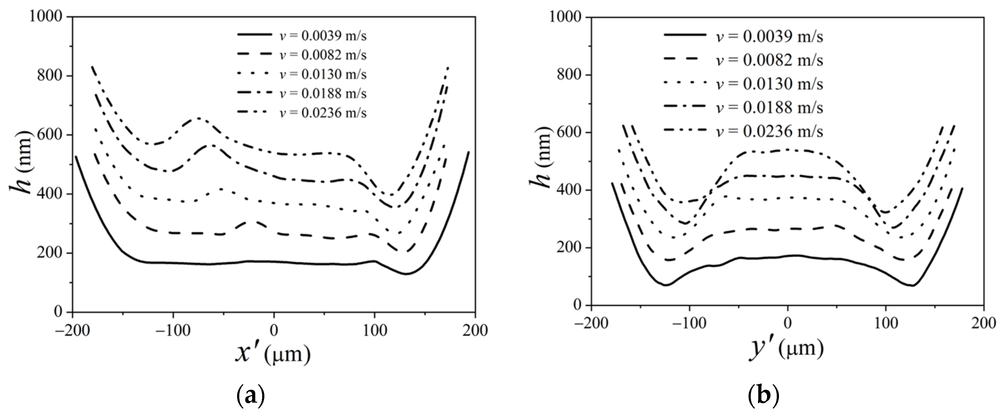
For Ssp = 0.1 and w = 18.5 N (W = 9.8 × 10⁻⁷), Figure 6 and Figure 7 show film interferometry images and film thickness profiles with different disk velocities on the x′-axis and y′-axis, respectively, where the entrainment at the contact point uR = 0.5 v. From Figure 7, the horseshoe shapes become obvious, and an inlet dimple appears as the velocity is high enough. In such circular contact, along the outlet (downstream in the x′-axis) and along the sides, there is a horseshoe-shaped constriction that prevents the lubricant from leaking out and balances the flows. The minimum film thickness will occur at two symmetrical positions along this horseshoe-shaped ridge, that is, on both sides at “earlobes” away from the centerline.
Figure 7a illustrates profiles of film thickness on the x′-axis (y′ = 0); the film is flat when the velocity is low, and its thickness increases with increasing velocity. Moreover, the dimple depth increases and moves towards the inlet area when the velocity increases. The film thickness on the y′-axis (x′ = 0) is shown in Figure 7b, and we can observe that, as the velocity increases, the film thickness increases, and the difference of the film thickness between the two sides becomes large. In addition, because of the side leakage in the y′ direction, the film thickness in the y′ direction is less than that in the x′ direction.
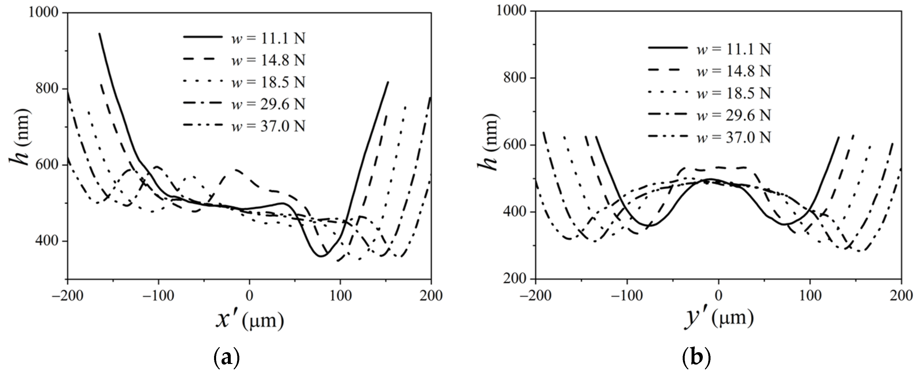
Figure 8 and Figure 9 present the interference images and film thickness profiles on the x′-axis and y′-axis, respectively, with various loads for Ssp = 0.1 and v = 0.0188 m/s. It can be observed from Figure 9 that, when the load is light, such as w = 11.1 N, there is no inlet dimple. A dimple is generated near the center of the contact region and moves to the inlet area when the load increases to a certain value (w = 18.5 N). As the load increases, the contact radius increases, and the horseshoe shape in the oil film interferogram becomes thinner and longer. It can be observed from the film thickness on the x′-axis in Figure 9a that, as the load increases, the depth of the dimple decreases slightly. Moreover, the film exit constriction moves towards the outlet. From Figure 9b, with the increase in the load, the central film thickness on the y′-axis changes little except for w = 14.8 N. Note that the large central film thickness for w = 14.8 N is caused by the central dimple.
Therefore, when the load and the velocity are large enough, a dimple will appear in the contact region and move toward the inlet.

3.3. Effects of the Spinning Factor under Fully Flooded Lubrication

For w = 18. 5 N and uR = 0.0094 m/s, the moderate parameters for a dimple formation, the film interferometry images and the film thickness profiles with the spinning factor on the x′-axis (y′ = 0) and y′-axis (x′ = 0), respectively, are shown in Figure 10 and Figure 11. It can be observed from Figure 11 that, as the spinning factor increases, the inlet deviates distally to the center of rotation, owing to the cavitation, the asymmetry of the film shape increase, the horseshoe shape, and the dimple depth change.
From the film thickness profiles on the x′-axis in Figure 11a, it can be found that, as Ssp = 0.3, due to the large spinning component, the depth of the dimple and the exit constriction are large, and the difference of the film thickness between the inlet and the outlet is significant. As the spinning factor is less than 0.1, with the decrease in the spin factor, the film thickness decreases, and there is a small difference when the spinning factors are 0.06 and 0.03. As the spinning factor increases, the film thickness proximal to the center of rotation becomes less.
Figure 11b shows the profile of the oil film on the x′ = 0 section. It can be observed that, when the spinning factor decreases, the asymmetry of the film thickness is converted to symmetry. When Ssp = 0.3, due to a larger spinning component, the difference in the oil film thickness between the two sides is apparent. When the spinning factor is less than 0.1, the difference between the two sides decreases. When Ssp = 0.03, because the spinning becomes weaker, the film thickness on both sides is basically equal, corresponding to symmetric interferometry in Figure 10. As the spinning factor decreases, the central film thickness remains essentially unchanged because the central entrainment velocity remains constant.

3.4. Effects of Inlet-Starvation Position on Spinning EHL

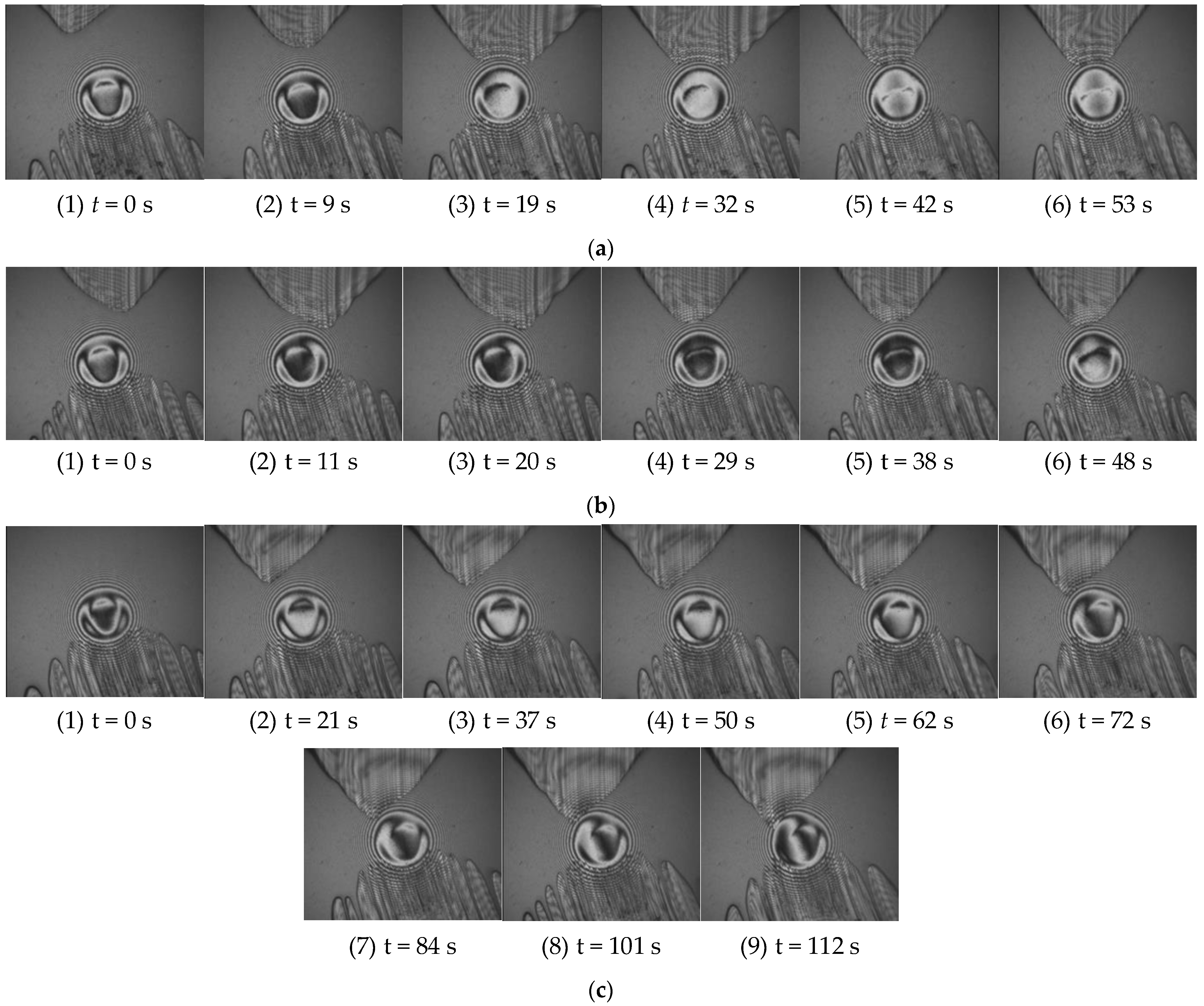
When controlling the volume of the oil supply, the high-speed side usually experiences oil starvation, resulting in a decrease in the film thickness. By maintaining a constant volume of the oil supply and studying the effect of the entrance oil-starvation position on the spin EHL performance under a certain load and speed, Figure 12 presents three different inlet-starvation positions: (1) oil starvation located in the middle position of the inlet, (2) oil starvation located at the low-speed end, i.e., proximal to the center of rotation of the entrance region, and (3) oil starvation located at the high-speed end, i.e., distal to the center of rotation of the inlet area. Interferometry images obtained at different instants are continuously collected. Figure 12a,b correspond to uR= 0.0106 m/s and Ssp = 0.1, while Figure 12c corresponds to uR= 0.01415 m/s and Ssp = 0.1. Corresponding to Figure 12, Figure 13 shows the variation in the central film thickness, minimum film thickness, and position of the inlet meniscus position with time.
Figure 12a presents the optical interference pattern of the oil film when the oil starvation is located in the middle part of the inlet. As can be observed from Figure 12a, as the degree of oil starvation increases, the influence of the spin on the film thickness at both sides is reduced, and the inlet dimple changes the original shape and moves towards the center of the contact region. When the oil starvation becomes more severe, the inlet meniscus approaches the Hertzian contact zone over time, and the shape of the oil film changes, transitioning from the circular shape at moments 1 (t = 0 s) and 2 (t = 9 s) to the pear shape at moments 5 (t = 42 s) and 6 (t = 53 s), forming a trapezoidal zone of oil starvation at the inlet. Corresponding to Figure 12a, Figure 13a shows the central film thickness, minimum film thickness, and position of the inlet meniscus at different moments. It can be observed that the central film thickness and minimum film thickness decrease, and the position of the inlet meniscus moves towards the contact zone over time. However, due to the spin effect, the meniscus has not yet reached the contact zone.
Figure 12b illustrates the oil film interference pattern when the oil starvation is on proximal to the center of rotation of the contact zone entrance, i.e., the low-speed side. Due to insufficient oil supply proximal to the center of rotation, the asymmetry of the oil film on both sides intensifies at moments 2 (t = 11 s) and 3 (t = 20 s). Because of the presence of spin motion, after some time, at moments 4 (t = 29 s) to 6 (t = 48 s), the oil-starvation zone gradually moves to the middle part of the inlet, and the asymmetry caused by the oil starvation gradually recovers with the oil starvation remaining in the middle part of the contact zone entrance. Subsequently, the shape of the oil film also changes, transitioning from the circular shape in the first three moments to the pear shape at moment 6, indicating a severe oil starvation. Corresponding to Figure 12b, Figure 13b shows the central film thickness, minimum film thickness, and position of the inlet meniscus at different moments. The central film thickness and minimum film thickness slightly decrease over time, and the position of the inlet meniscus moves towards the contact zone, showing a trend similar to Figure 13a.
Figure 12c depicts the oil film interference pattern when the oil starvation is distal to the center of rotation of the contact zone entrance, i.e., the high-speed side. Due to the combined effects of spin and oil starvation, the original symmetry gradually disappears, and the meniscus approaches the Hertzian contact zone, leading to a further increase in the oil starvation on the high-speed side. As the oil starvation on the low-speed side increases, the asymmetry of the oil film shape intensifies, and the inlet dimple moves to the other side of the oil starvation and becomes shallower, but the oil starvation zone still remains on the high-speed side of the contact zone entrance until the oil film ruptures. As observed from Figure 13c, as time goes by, the central film thickness and minimum film thickness first decrease and then remain constant, and the position of the inlet meniscus has entered the Hertzian contact zone.

3.5. Effects of Oil-Supply Quantity on Spinning EHL

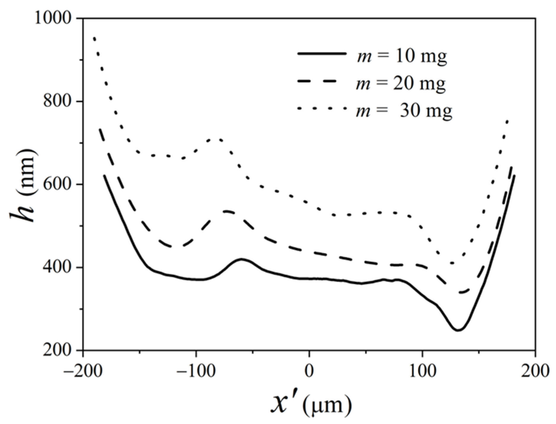
The lubricant is supplied at contact point O. Figure 14 shows the optical interferometry images with three oil-supply quantities, m, for w = 14.8 N, uR = 0.01415 m/s, and Ssp = 0.1 after running 120 min of the experiment. It can be found that, when the oil-supply quantity is 30 mg, no starvation appears, and it indicates fully flooded lubrication for the contact region. However, starvation occurs when the oil-supply quantity is 20 mg and 10 mg, respectively. The position of the meniscus approaches the Hertzian contact region as the oil-supply quantity is 10 mg. In addition, the positions of the meniscus are all at the high-speed side of the contact, which proves again that the high-speed side is easily starved due to the spinning motion.
From the profiles of the film thickness in Figure 15, it can be observed that the larger the oil-supply quantity, the larger the film thickness; moreover, the inlet dimple is further away from the contact center. Therefore, the oil-supply quantity has some influence on the lubrication status in spinning–sliding EHL.

4. Discussion

The conventional EHL film shape features a fairly flat central contact region and a constriction at the outlet. However, there is a deep dimple rather than a flat plateau in the central part of the contact for the non-conventional EHL film in the range of high sliding speeds. The inlet dimple is a film shape feature that refers to a small dimple at the inlet [28]. The inlet dimple in Figure 4 is generated in spinning–slide EHL due to the thermal-viscosity wedge effect because thermal effects are more obvious than those in [14] when the speed is high. However, there is no dimple in the spinning–rolling condition, and the reason is that the dimple is caused by the shear, but the shear is very small for the spinning–rolling case.
Cameron [29] referred to the changes in Couette flow owing to viscosity gradients, recognized as the ‘viscosity wedge’ action. The ‘viscosity wedge’ action would attribute the formation of the dimple to the temperature distribution in the film measured with the experiments, and the Couette flow, considering the ‘viscosity wedge’ action based on the results of the temperature measurements, can explain the dimple formation under the EHL conditions [30]. Under high sliding conditions, the shear heating that occurs in the contact area produces a complex temperature distribution in the film. As a result, the temperature distribution produced in the lubricant film becomes asymmetrical, resulting in the appearance of viscosity gradients across the film [30,31]. So, an extra pressure peak is generated, and thus, a dimple is formed [3].
The mechanism of the thermal-viscosity wedge effect has been confirmed, and the numerical simulation results are in good agreement with the experimental results [3,32]. The dimple and temperature distribution caused by the thermal effect have also been experimentally observed and measured by Yagi et al. [30,31,33,34,35,36,37]. But at the present stage, it is impossible for us to observe the temperature distributions in EHL contacts due to the limitation of the test device.
The larger the velocity, the deeper is the dimple, and the greater is the difference of the film thickness between the two sides of the contact area, as shown in Figure 7. The dimple depth increases and moves towards the inlet area when the velocity increases. The dimple is mainly dependent on the shear, and the shear is larger when the velocity is larger. So, the depth of the dimple becomes larger, and the effect of velocity is obvious. This is coherent with Guo’s conclusion [28] that the inlet dimple has obvious dependence on entrainment speed. The velocity difference between the two sides of the contact area becomes larger due to the spinning motion. Hence, the difference of the film thickness between the two sides along the y′ direction becomes larger. As the offset r is fixed, the velocity increase means there is an increase in the spinning angular speed ω, as shown in Figure 2b; both the velocity u1L distal to the center of rotation of the contact region, ω(r + a), and the velocity u1R proximal to the center of rotation of the contact region, ω(ra), increase. Moreover, the velocity difference, 2ωa, between the two sides increases much more, so the difference of the film thickness between the two sides becomes large. To avoid influential shear heating, Jiang et al. [14] employed ultra-low entrainment speed. However, the speed in our experiment is much higher than that in [14], so the thermal effects are significant. Therefore, the inlet dimple is related to the thermal-viscosity wedge mechanism [3].
As the load increases, the difference between the two sides increases, as shown in Figure 9. This is because the contact radius increases, the effects of the spinning on the film thickness at the left side of the contact are more obvious, and the film thickness decreases, whereas the film thickness proximal to the center of rotation declines due to weak spinning effects.
As shown in Figure 10 and Figure 11, the spinning component has much more influence on the exit film constriction and the dimple. As the spinning factor increases, from Equation (2), it means that the distance r between the rotational center and the contact center decreases; so, the area proximal to the center of rotation is closer to the rotational center. The spinning effects are so strong that the film thickness proximal to the center of rotation becomes less. Therefore, the larger the spinning factor, the less the r, and the contact center is closer to the rotational center. The effects of spinning are significant. They will change the supply of the lubricant, drag the cavitation region from the exit to the inlet, and contribute to the film thickness at the exit film constriction. It should be noted that the inlet flow condition is different for different distance r with the same oil supply. When r is infinity, this is a simple-slide problem, and the oil flows along the entrainment direction. When r = 0, the oil flows around the center of the rotation. When r > 0, the oil flows along the entrainment direction and around the center of the rotation for the spinning–sliding case.
Previous studies reveal that spinning causes an asymmetric film thickness distribution, as shown in Figure 5, producing a local maximum and minimum value at each side of the contact area. From the film thickness profiles in the y′ direction where the oil starvation does not occur, as shown in Figure 2, it can be observed that the oil film thickness distal to the center of rotation is generally thicker. This is because, on one hand, the area distal to the center of rotation has a higher velocity, leading to a thicker oil film. On the other hand, due to the presence of spin motion, the cavitation in the exit region rotates towards the high-speed side of the entrance region, causing asymmetric oil supply and the shape of the oil film [14]. Starvation reduces the overall film thickness of the whole contact area [21].
The inlet-starvation positions on the EHL film are different, as shown in Figure 12 and Figure 13. When the starvation is in the middle part of the inlet area, the starvation becomes more severe with time, the round shape of the film changes into the pear shape, and the inlet-starvation area keeps stable. This phenomenon is caused by the spinning. The oil-supplied quantity in the middle part of the inlet is almost fixed compared to the two sides of the contact area. As the time goes past, the extra oil cannot be supplied; therefore, the inlet starvation becomes severe.
When the inlet-starvation position is proximal to the center of rotation, i.e., the low-speed side of the contact region, the asymmetry of the film thickness on the two sides becomes significant at first and then weakens. The reason is that the high-speed side is starved easily compared to the low-speed side of the contact region, and it requires a greater lubricant supply to sustain the lubricant film. Unfortunately, the lubricant supply volume is fixed. The lubricant volume that transports from the low-speed side to the high-speed side is less than that from the high-speed side to the low-speed side due to the spinning motion, so the high-speed side cannot be supplied with much more lubricant, and it begins to starve. Hence, the starvation position is extended quickly from the low-speed side toward the high-speed side for spinning EHL, and the inlet-starvation position goes back to the middle part of the inlet approximately vs. time.
It is revealed that starvation occurred when the speed of the bearing became high [38,39]. For the starvation position distal to the center of rotation of the inlet area, i.e., the high-speed side, the starvation distal to the center of rotation becomes more severe. The reason is that the high-speed side needs a high oil-supply quantity, but the lubricant supply is limited. As mentioned before, due to the spinning effects, the lubricant supply on the high-speed side may be less than that of the low-speed side, so the starvation becomes severe over time on this position. With the increase in the starvation distal to the center of rotation, the asymmetry of the film shape becomes obvious, and the inlet dimple moves proximal to the center of rotation. However, the oil starvation still exists distal to the center of rotation of the inlet area until the oil film ruptures. It can be concluded that, as the starvation position is on the high-speed side of the contact, i.e., distal to the center of rotation of the inlet area, failure of the lubricant film and a risk of wear will be generated due to severe inlet starvation.
In the future, further study would focus on thermal effects on the dimple in spinning EHL for roller-end/flange contact.

5. Conclusions

A test rig for spinning EHL interferometry was built to investigate the spinning lubricating performance. The effects of the speed, the load, and the spinning factor under fully flooded lubrication have been discussed, and the effects of the inlet-starvation position and the oil-supply quantity on spinning EHL have been investigated. The main conclusions are as follows.
The classical symmetry of the horseshoe shape is lost for spinning–rolling and spinning–sliding EHL conditions due to spinning, and a local maximum and minimum film thickness is produced distal and proximal to the center of rotation. Different from the spinning–rolling case, a dimple is generated upon the spinning–sliding condition because of the thermal effects caused by large sliding.
At the spinning–sliding case, the difference between the areas distal and proximal to the center of rotation becomes larger with increasing speed and load. With the increase in the spinning factor, the difference of the film thickness distal and proximal to the center of rotation becomes large, but the central film thickness keeps constant due to the nearly constant velocity. When the spinning factor is large enough, the distance r between the rotational center and the contact center decreases, and the effects of the spinning motion on the inlet dimple and the exit constriction are evident.
The dimple is caused by a combined effect of both the speed and the load. The mechanism of the dimple is the thermal effects; because the speed is high, the thermal-viscosity wedge is the mechanism that forms the dimple. The dimple is generated near the center of the contact region and moves towards the inlet area as the load and the speed increase to a certain value.
The effects of the inlet-starvation position on the EHL film are different. When the starvation is on the side of low speed, i.e., proximal to the center of rotation, the spinning motion will lead to the inlet-starvation position extending from proximal to distal to the center of rotation because the high-speed side is starved easily. When the starvation happens on the high-speed side, i.e., distal to the center of rotation, the starvation at this position becomes much more severe, and lubricating failure and a risk of wear will be generated.

Author Contributions

Validation, M.M. and T.L.; investigation, W.L.; resources, W.L.; data curation, X.L.; writing—original draft preparation, W.L. and X.L.; writing—review and editing, Q.M.; supervision, F.G. All authors have read and agreed to the published version of the manuscript.

Funding

This research was funded by the National Natural Science Foundation of People’s Republic of China, grant number 51475250, and the ‘Taishan Scholar’ Talents Project from Shandong province, grant number No. TS20190943.

Data Availability Statement

Not applicable.

Acknowledgments

The authors are so grateful to the valuable suggestion from Peiran Yang and Xinming Li during the study.

Conflicts of Interest

The authors declare no conflict of interest.

References

  1. Cheng, H.S.; Sternlicht, S. A Numerical Solution for the Pressure, Temperature, and Film thickness Between Two Infinitely Long, Lubricated Rolling and Sliding Cylinders, Under Heavy Loads. ASME J. Basic Eng. 1965, 87, 695–707. [Google Scholar] [CrossRef]
  2. Zhu, D.; Wen, S. A Full Numerical Solution of the Thermal Elastohydrodynamic Lubrication Problem of Elliptic Contact. ASME J. Tribol. 1984, 106, 246–254. [Google Scholar] [CrossRef]
  3. Yang, P.; Qu, S.; Kaneta, M.; Nishikawa, H. Formation of Steady Dimples in Point TEHL Contacts. ASME J. Tribol. 2001, 123, 42–49. [Google Scholar] [CrossRef]
  4. Liu, X.; Jiang, M.; Yang, P.; Kaneta, M. Non-Newtonian Thermal Analyses of Point EHL Contacts Using the Eyring Model. ASME J. Tribol. 2005, 127, 70–81. [Google Scholar] [CrossRef]
  5. Shi, X.; Wang, L.; Mao, Y.; Qin, F. Coupling Study on Dynamics and TEHL Behavior of High-Speed and Heavy-Load Angular Contact Ball Bearing with Spinning. Tribol. Int. 2015, 88, 76–84. [Google Scholar] [CrossRef]
  6. Miller, S.T.; Parker, R.J.; Zaretsky, E.V. Apparatus for Studying Ball Spinning Friction; NASA Report, NASATN D-2796; National Aeronautics and Space Administration: Washington, DC, USA, 1965.
  7. Parker, R.J.; Zaretsky, E.V.; Anderson, W.J. Spinning Friction Coefficients with Three Lubricants. ASME J. Lubr. Tech. 1968, 90, 330–335. [Google Scholar] [CrossRef]
  8. Dietrich, N.W.; Parker, R.J.; Zaretsky, E.V.; Anderson, W.J. Contact Conformity Effects on Spinning Torque and Friction. ASME J. Lubr. Tech. 1969, 68, 308–313. [Google Scholar] [CrossRef]
  9. Allen, C.W.; Townsend, D.P.; Zaretsky, E.V. Elastohydrodynamic Lubrication of a Spinning Ball in a Nonconforming Groove. ASME J. Lubr. Tech. 1970, 92, 89–95. [Google Scholar] [CrossRef]
  10. Thorp, N.; Gohar, R. Oil Film Thickness and Shape for a Ball Sliding in a Grooved Raceway. ASME J. Lubr. Tech. 1972, 94, 199–204. [Google Scholar] [CrossRef]
  11. Johnson, K.L.; Roberts, A.D. Observation of Viscoelastic Behaviour of an Elastohydrodynamic Lubrication Film. Proc. R. Soc. Lond. A Math. Phys. Sci. 1974, 337, 217–242. [Google Scholar]
  12. Dowson, D.; Taylor, C.M.; Xu, H. Elastohydrodynamic Lubrication of Elliptical Contacts with Pure Spin. Proc. Inst. Mech. Eng. Part C Mech. Eng. Sci. 1993, 207, 83–92. [Google Scholar] [CrossRef]
  13. Wedeven, L.D.; Evans, D.; Cameron, A. Optical Analysis of Ball Bearing Starvation. ASME J. Lubr. Technol. 1971, 93, 349–353. [Google Scholar] [CrossRef]
  14. Jiang, P.; Li, X.M.; Guo, F.; Chen, J. Interferometry Measurement of Spin Effect on Sliding EHL. Tribol. Lett. 2009, 33, 161–168. [Google Scholar] [CrossRef]
  15. Li, X.M. Influence of Spinning on the Rolling EHL Films. Tribol. Int. 2010, 43, 2020–2028. [Google Scholar] [CrossRef]
  16. Dormois, H.; Fillot, N.; Habchi, W.; Dalmaz, G.; Vergne, P.; Morales-Espejel, G.E.; Ioannides, E. A Numerical Study of Friction in Isothermal EHD Rolling-Sliding Sphere-Plane Contacts with Spinning. J. Tribol. 2010, 132, 021501. [Google Scholar] [CrossRef]
  17. Liu, X.; Long, T.; Li, X.; Guo, F. Thermal EHL Analysis of the Inner Ring Rib and Roller End in Tapered Roller Bearings with the Carreau Model. Front. Manuf. Technol. 2023, 2, 1029860. [Google Scholar] [CrossRef]
  18. Gu, C.; Meng, X.; Xie, Y. A Universal Model for Both Flooded and Starved Lubrication Regimes and its Application in Ring-Liner System. Tribol. Trans. 2017, 60, 506–515. [Google Scholar] [CrossRef]
  19. Colin, F.; Chevalier, F.; Chaomleffel, J.-P.; De Mul, J.; Dalmaz, G. Starved Elastohydrodynamic Lubrication of the Rib-Roller End Contact in Tapered Roller Bearings: Film Thickness, Traction and Moments. In Proceedings of the 24th Leeds-Lyon Symposium on Tribology “Tribology for Energy Conservation”, London, UK, 4–6 September 1997; Tribology Series; Elsevier: Amsterdam, The Netherlands, 1998; Volume 34, pp. 253–263. [Google Scholar]
  20. Vazquez, A.P. Lubricant Starvation in Elastohydrodynamic Large-Size Spinning Contacts. Ph.D. Thesis, University of Lyon, Lyon, France, 2020. [Google Scholar]
  21. Vazquez, A.P.; Fillot, N.; Vergne, P.; Philippon, D.; Morales-Espejel, G.E. Influence of Spin on Film Thickness in Elastohydrodynamic Starved Point Contacts. Tribol. Int. 2021, 156, 106825. [Google Scholar] [CrossRef]
  22. Wu, Z.; Xu, Y.; Liu, K. Study on Logarithmic Crowning of Tapered Roller Profile Considering Angular Misalignment. ASME J. Tribol. 2020, 142, 111201. [Google Scholar] [CrossRef]
  23. Wirsching, S.; Marian, M.; Bartz, M.; Stahl, T.; Wartzack, S. Geometrical Optimization of the EHL Roller Face/Rib Contact for Energy Efficiency in Tapered Roller Bearings. Lubricants 2021, 9, 67. [Google Scholar] [CrossRef]
  24. Maccioni, L.; Chernoray, V.G.; Mastrone, M.N.; Bohnert, C.; Concli, F. Study of the Impact of Aeration on the Lubricant Behavior in a Tapered Roller Bearing: Innovative Numerical Modelling and Validation Via Particle Image Velocimetry. Tribol. Int. 2022, 165, 107301. [Google Scholar] [CrossRef]
  25. Liu, Y.; Kang, W.; Zhu, Y.; Yan, K.; Hong, J. Effects of Defect on Roller Raceway Contact State and Friction Torque of Tapered Roller Bearings. ASME J. Tribol. 2020, 142, 111501. [Google Scholar] [CrossRef]
  26. Gao, P.; Tang, W.; Cui, Y.; Wang, Y.; Mo, G.; Yin, J. Theoretical and Experimental Investigation on Thermal Characteristics of Railway Double-Row Tapered Roller Bearing. Energies 2022, 15, 4217. [Google Scholar] [CrossRef]
  27. Guo, F.; Wong, P.L. A Wide Range Measuring System for Thin Lubricating form: From Nano to Micro Thickness. Tribol. Lett. 2004, 17, 521–531. [Google Scholar] [CrossRef]
  28. Guo, F.; Wong, P.L. An Anomalous Elastohydrodynamic Lubrication Film: Inlet Dimple. ASME J. Tribol. 2005, 127, 425–434. [Google Scholar] [CrossRef]
  29. Cameron, A. The viscosity wedge. ASLE Trans. 1958, 1, 248–253. [Google Scholar] [CrossRef]
  30. Yagi, K.; Kyogoku, K.; Nakahara, T. Relationship Between Temperature Distribution in EHL Film and Dimple Formation. ASME J. Tribol. 2005, 127, 658–665. [Google Scholar] [CrossRef]
  31. Yagi, K.; Kyogoku, K.; Nakahara, T. Experimental Investigation of Effects of Slip Ratio on Elastohydrodynamic Lubrication Film Related to Temperature Distribution in Oil Films. Proc. Inst. Mech. Eng. Part J J. Eng. Tribol. 2006, 220, 353–363. [Google Scholar] [CrossRef]
  32. Qu, S.; Yang, P.; Guo, F. Theoretical Investigation on the Dimple Occurence in the Thermal EHL of Simple Sliding Steeling Steelnce in Contacts. Tribol. Int. 2000, 33, 59–65. [Google Scholar] [CrossRef]
  33. Yagi, K.; Vergne, P. Abnormal Film Shapes in Sliding Elastohydrodynamic Contacts Lubricated by Fatty Alcohols. Proc. Inst. Mech. Eng. Part J J. Eng. Tribol. 2007, 221, 287–300. [Google Scholar] [CrossRef]
  34. Nakahara, T.; Yagi, K. Influence of Temperature Distributions in EHL Film on its Thickness under High Slip Ratio Conditions. Tribol. Int. 2007, 40, 632–637. [Google Scholar] [CrossRef]
  35. Yagi, K.; Vergne, P.; Nakahara, T. In Situ Pressure Measurements in Dimpled Elastohydrodynamic Sliding Contacts by Raman Microspectroscopy. Tribol. Int. 2009, 42, 724–730. [Google Scholar] [CrossRef]
  36. Yagi, K.; Sugimura, J.; Vergne, P. Rheological Response of Fatty Alcohols in Sliding Elastohydrodynamic Contacts. Tribol. Int. 2012, 49, 58–66. [Google Scholar] [CrossRef]
  37. Yagi, K.; Kyogoku, K.; Nakahara, T. Mechanism of Dimple Formation under Elastohydrodynamic Conditions. In Tribological Research and Design for Engineering Systems: Proceedings of the 29th Leeds–Lyon Symposium on Tribology, Leeds, UK, 3–6 September 2002; Elsevier: Amsterdam, The Netherlands, 2003; pp. 111–120. [Google Scholar]
  38. Maruyama, T.; Nakano, K. In Situ Quantification of Oil Film Formation and Breakdown in EHD Contacts. Tribol. Trans. 2018, 61, 1057–1066. [Google Scholar] [CrossRef]
  39. Maruyama, T.; Maeda, M.; Nakano, K. Lubrication Condition Monitoring of Practical Ball Bearings by Electrical Impedance Method. Tribol. Online 2019, 14, 327–338. [Google Scholar] [CrossRef]
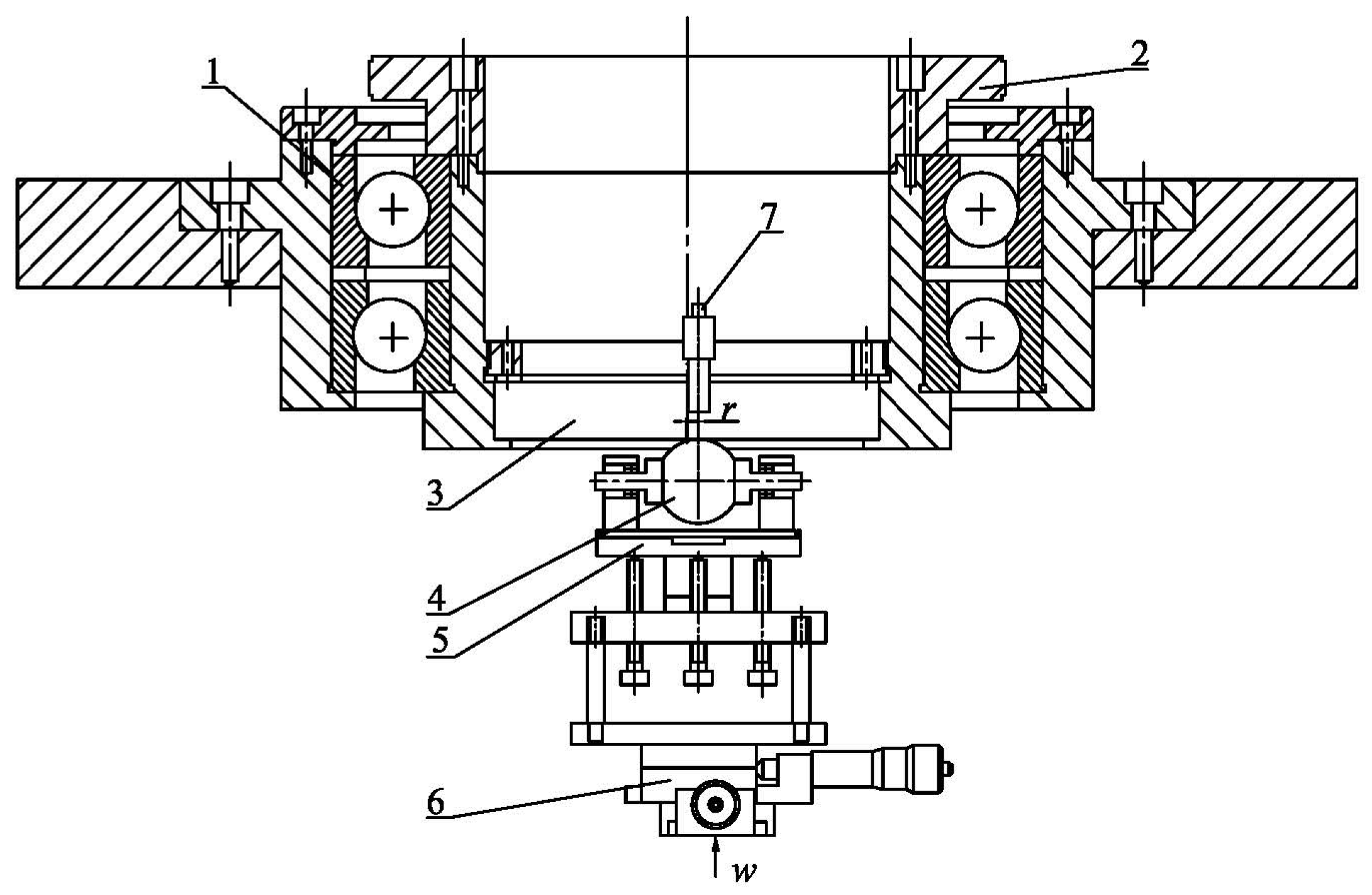
Figure 1. Ball–disc system. 1. Bearings; 2. Synchronous pulley; 3. Glass disk; 4. Steel ball; 5. Skew unit; 6. XY table; 7. Camera.
Lubricants 11 00451 g001
Figure 2. Schematic of a point-contact EHL with spinning and velocity analysis. (a) Spinning EHL model; (b) Velocity analysis; (c) Velocity decomposition.
Lubricants 11 00451 g002
Figure 3. Schematic diagram of the optical interference image.
Lubricants 11 00451 g003
Figure 4. Film interferometry images for spinning–sliding and spinning–rolling EHL status for w = 40 N, Ssp = 0.1, and uR = 0.0094 m/s: (a) Spinning–rolling; (b) Spinning–sliding.
Lubricants 11 00451 g004
Figure 5. Illustration for spinning EHL results.
Lubricants 11 00451 g005
Figure 6. Optical interferometry images with different velocities for Ssp = 0.1 and w = 18.5 N.
Lubricants 11 00451 g006
Figure 7. Profiles of film thickness with different velocities for Ssp = 0.1 and w = 18.5 N: (a) x′-axis (y′ = 0); (b) y′-axis (x′ = 0).
Lubricants 11 00451 g007
Figure 8. Optical interferometry images with different loads for Ssp = 0.1 and uR = 0.0094 m/s.
Lubricants 11 00451 g008
Figure 9. Curves of the film thickness with different loads for Ssp = 0.1 and uR = 0.0094 m/s: (a) x′-axis (y′ = 0); (b) y′-axis (x′ = 0).
Lubricants 11 00451 g009
Figure 10. Optical interferometry images with spinning factors for w = 18.5 N and uR = 0.0094 m/s.
Lubricants 11 00451 g010
Figure 11. Profiles of the film thickness with different spinning factors for w = 18.5 N and uR = 0.0094 m/s: (a) x′-axis (y′ = 0); (b) y′-axis (x′ = 0).
Lubricants 11 00451 g011
Figure 12. The influence of the inlet-starvation position: (a) Starvation in the middle part of the inlet for uR = 0.0106 m/s and Ssp = 0.1; (b) Inlet starvation proximal to the center of rotation for uR = 0.0106 m/s and Ssp = 0.1; (c) Inlet starvation distal to the center of rotation for uR = 0.01415 m/s and Ssp = 0.1.
Lubricants 11 00451 g012
Figure 13. Variations in central and minimum film thickness and inlet-starved position symbolically by triangle with cross versus time: (a) Middle part starvation for uR = 0.0106 m/s and Ssp = 0.1; (b) Inlet starvation proximal to the center of rotation for uR = 0.0106 m/s and Ssp = 0.1; (c) Inlet starvation distal to the center of rotation for uR = 0.01415 m/s and Ssp = 0.1.
Lubricants 11 00451 g013
Figure 14. Optical interferometry images with three oil-supply quantities for w = 14.8 N, uR = 0.01415 m/s, Ssp = 0.1, and PB950: (a) m = 30 mg; (b) m = 20 mg; (c) m = 10 mg.
Lubricants 11 00451 g014
Figure 15. Profiles of the film thickness of three oil-supply quantities on the x′ direction (y′ = 0) for w = 14.8 N, uR = 0.01415 m/s, Ssp = 0.1, and t = 120 min.
Lubricants 11 00451 g015
Table 1. Properties of the lubricant.
LubricantDynamic Viscosity (Pa·s) @ 20 °CDynamic Viscosity (Pa·s) @ 100 °CDensity (kg·m−3) @ 20 °CRefractive Index
PB95027.50.201 890 1.497
Table 2. Comparison of contact radius between the theory and experiment under dry contact.
Load (N)10203040
Theoretical a (μm)120149175188
Experimental a (μm)122150176188
Disclaimer/Publisher’s Note: The statements, opinions and data contained in all publications are solely those of the individual author(s) and contributor(s) and not of MDPI and/or the editor(s). MDPI and/or the editor(s) disclaim responsibility for any injury to people or property resulting from any ideas, methods, instructions or products referred to in the content.