Abstract
This paper presents a transient mixed-lubrication hydrodynamic and gas flow simulation model for a piston ring pack for a four-stroke internal combustion engine. The analyses carried out compare two fuel types, hydrogen and gasoline, at a 2000 rpm low engine load (20%), as well as 3000 rpm low (20%) and high (100%) engine loads, to investigate the effects of the different fuels and loading conditions on the ring pack. In particular, the minimum oil film thickness at the top compression ring, the total ring friction of the ring pack, the friction power loss and the blow-by are studied. The simulation shows that, under the high load conditions at 3000 rpm, the hydrogen variant exhibits larger friction power losses, around a 200 W peak difference and larger blow-by throughout the expansion stroke of the engine cycle. A similar trend can be observed for the low loads, where larger friction power losses with peak differences of 30 W and 40 W for 2000 rpm and 3000 rpm, respectively, are observed. The blow-by results for the low load at 2000 rpm show a slight increase of approximately 22% more gas flow into the crankcase, while the 3000 rpm simulation shows a 50% increase in blow-by for the hydrogen variant at low load and a 40% increase at high load. The findings that are presented indicate that, although alternative fuel sources such as hydrogen are very attractive alternatives to fossil fuels such as gasoline, there can be unwanted side effects that could lead to the permanent damage of components through quicker wear or hydrogen embrittlement from the blow-by gas.
1. Introduction
Reducing global emissions is of great interest, and presents engineers across the globe with significant challenges across the automotive and powertrain sectors, especially due to the stringent demands set by governments and legislators around the globe [1]. A mix of powertrain options are now available with the rise of electric and fuel cell vehicles, while the internal combustion engine (ICE) remains at large as alternative fuel sources are sought out to improve upon the overall system efficiency, as well as the noise, vibration and harshness (NVH) [2]. Alternative fuel technology is of great interest to the powertrain industry, whether it be natural gas, LPG, hythane or hydrogen. For spark-ignited ICEs, there is increasing interest in hydrogen as a fuel. Hydrogen-fueled ICEs are viable alternatives that do not produce any so-called tank-to-wheel CO2 tailpipe emissions [3]. The “hydrogen economy” continues to be one of the highest potential ways to provide a sustainable source of energy [4,5,6] and it is strongly believed that hydrogen ICEs can provide not only a reliable and durable solution to help transition towards carbon-free mobility, but also a cost-efficient one based on well-established and known technology.
Hydrogen engines can run on hydrogen that is of a lower purity than that required for a fuel cell [7]. This can be advantageous in the powertrain industry, as the transition to higher-quality and green hydrogen will take time. Another advantage is that hydrogen engines can be built using well-established technology from ICEs; this means that many parts can be re-used so that manufacturers can have a greater focus on the optimization of existing technologies rather than developing something new from scratch [8]. When compared directly to gasoline engines, port-fuel-injected hydrogen combustion has been shown to provide higher efficiency and very low emissions [9]. However, it was also observed in the same study that there was a reduced power output of the engine due to the volumetric efficiency of the engine being reduced. Hydrogen ICEs are also reported to produce more NOx emissions, as they require much higher combustion temperatures than gasoline [10].
The Otto cycle can be used to analyze the performance of hydrogen-fueled ICEs [11]. Using the Otto cycle, it is possible to identify several methods to theoretically improve the efficiency of hydrogen ICEs [12]; for example, by increasing the compression ratio, the power output could be enhanced. Another alternative to improve the efficiency of a hydrogen ICE would be to introduce more air into the chamber using a booster, such as a turbocharger, to increase the amount of complete combustion, improving the volumetric efficiency [13]. This was demonstrated by Lee et al., who compared a naturally aspirated and a turbo-charged port-fuel-injected hydrogen engine, finding that the engine power of the turbo-charged engine was increased by 41% [14].
An unwanted side effect of ICE operation is blow-by. Maximum blow-by occurs during the power stroke, when the pressure in the combustion chamber is highest and gas passes via the piston rings into the crankcase. In general, blow-by occurs at higher engine speeds and loads, as the gas flow is driven by large pressure differentials between the combustion chamber and the crankcase. As well as leading to reduced operational efficiency, blow-by can have a significant influence on the lubrication and damage the materials in an ICE. It has been reported that, in hydrogen-fueled engines, more blow-by occurs when compared to other engine fuels [15]. In the same study, it was noted that the lubricating oil has significant degradation in its properties following exposure to blow-by from a hydrogen-fueled engine. It was reported that both the lubricating and wear-resistive additives had greatly decreased, and the esters, which were found in the unused engine oil, had almost fully disappeared. Finally, it was also found that the oil viscosity had increased under atmospheric conditions, resulting in higher friction during startup, and decreased quickly as the temperatures rose to operating conditions, resulting in poor lubrication. Investigations and advancements have been made into alternative water-based and synthetic lubricants in recent years [16], as well as coating methods [17] and inlet particle road dust affecting wear in the ring pack [18]; however, these topics are out of scope for the current study and investigation.
Hydrogen-fueled ICEs tend to have higher rates of blow-by due hydrogen having a low density and due to the high in-cylinder pressures, resulting from high flame speeds and a fast burn rate [11]. The fast burn rate can be attributed to hydrogen having a wide flammability range, which means it can operate under very lean conditions. This, in turn, can lead to better fuel efficiency and emission-free combustion [19]. Hydrogen is also known to cause the embrittlement of iron and steel-based metals, which are commonly used in ICEs, that can reduce the ductility and the amount of stress that leads to failure. It has been found in studies [20] that the materials that are most sensitive to hydrogen embrittlement are nickel, titanium and their corresponding alloys, both of which are used for coating piston rings.
This paper compares a single-cylinder piston ring pack analysis for hydrogen and gasoline fuels to determine key characteristics through numerical simulations, which engineers should focus on during the design stage when evaluating the use of alternative fuel technologies in existing ICE power units. The side effects of hydrogen combustion can be lubricant degradation, leading to poor behavior within the ring-to-liner contact and resulting in bad efficiency, or hydrogen embrittlement, whereby the protective coatings can be destroyed or low-ductility regions form, resulting in component failure. The method of simulation is presented, and simulations are carried out at 2000 rpm at 20% engine load, and at 3000 rpm at 20% and 100% engine loads. At the time of writing, to the authors’ knowledge, such a numerical approach to comparing alternative fuel sources using simulation has not been reported in the literature.
2. Methodology
For this investigation, the numerical analysis of the piston ring friction is calculated using AVL EXCITETM Piston&Rings, a commercially available and industry-standard tool for tribodynamic simulation, in order to investigate engine friction, oil consumption and noise, vibration and harshness (NVH). In the simulation model, the piston rings and liner use a mixed friction model [21,22] as well as a gas flow model [23,24] in order to predict the amount of blow-by through the piston ring pack. An example of a validated simulation model compared to a single-cylinder test bed can be found in [25]. In addition, the further validation of the ring dynamics of the ring pack model against commercial finite element software can be found in [26].
3. Hydrodynamics
The Reynolds equation is applied to the contact for the representation of the oil film acting between two surfaces (the ring running face and the liner contact) and has been discretized using a finite volume method, with a ring surface discretization of 101 nodes on the ring running surface hydrodynamic mesh. The 1D Reynolds equation for a viscous compressible lubricant is
During simulation, the Reynolds equation is used to determine the hydrodynamic pressure within the tribo-contact whilst considering the density of the lubricant, the dynamic viscosity and the fill ratio. The Reynolds equation can be further extended to examine the effects of surface roughness for both isotropic and non-isotropic conditions, known as the averaged Reynolds equation [27,28], which is used as part of the simulation methodology:
where the pressure flow factor, , is
and the shear flow factor, , is
In order to guarantee mass conservation through the hydrodynamic contact, the Jakobsson–Floberg–Olsen (JFO) boundary conditions are applied [29,30]. The JFO boundary conditions introduce a fill ratio, , into the Reynolds equation, modeling the cavitation pressure, such that
Should the hydrodynamic pressure, , fall below the cavitation pressure (set to 500 MPa), the fill ratio is reduced in the cell, and vice versa; if the pressure is above cavitation pressure, the fill ratio is increased.
4. Lubricant Rheology
For the simulation, an SAE 5W-30 lubricant was specified, with the specific parameter details shown in Table 1.

Table 1.
Engine oil data.
The lubricant viscosity is temperature-dependent and calculated using Vogel’s equation:
An important consideration is that the Vogel viscosity model is dependent on all temperature values being provided in degrees Celsius. The lubricant oil temperature, , for each ring’s hydrodynamic grid cell is calculated from the liner inner wall surface temperature, and is linearly interpolated along the height of the liner. For this simulation, a 1D thermal profile was used from the top to the bottom of the liner, assuming no liner thermal distortions along the circumference. Furthermore, the lubricant is assumed to be Newtonian, so the viscosity remains constant with the increasing shear rate. This assumption is due to piston rings operating across the boundary and the mixed regimes of lubrication, where there is enough lubricant film to provide fully flooded lubrication, which can occur at mid-stroke. Only at the top and bottom dead centers, partial flooding can occur, as the piston speed is much slower. For this analysis, it is assumed that the inlet is fully flooded during the initial upstroke to help the mathematical model converge; after this, the mass conservation algorithm is applied to sustain good lubrication within the ring running face contact.
5. Asperity Contact Model
To predict the frictional losses due to the viscous shear of the thin lubricant film and the boundary friction, which results from the contact between two rough surfaces, we need to apply a contact model which considers the real surface topographies. To calculate this load share from the asperities, we use the model from Greenwood and Tripp [31,32]. The assumption of this model is that the summit heights have a Gaußian distribution; thus, the force–compliance relationship is based upon a statistical evaluation of all contact points. We can calculate the mean asperity pressure as
where the statistical function F5/2 is considered as
The mean asperity shear stress is then found using Coulomb’s friction law, such that
The approach reported by Offner and Knaus [21] is then applied to find a dimensionless friction coefficient which considers the abrasive, adhesive and micro-hydrodynamic components of friction. In combination with the lubrication number, this approach adjusts the friction coefficient at each grid cell of the hydrodynamic mesh relative to changes in the surface roughness, topography, dynamic viscosity and asperity pressure:
The total friction force generated within the contact can be calculated as
where the boundary friction, , and the viscous friction, , are found as the integrals of the asperity and hydrodynamic shear stresses.
6. Gas Flow Model
To find the gas forces, which act upon the piston rings, it is important to determine the pressures resulting from the gas flow. The method presented in [23,24] has been used to split the ring pack up into chambers, connected by orifices, as shown in Figure 1. As the combustion and crankcase pressures are known, a quasi-stationary calculation of the mass flow of the gas can be calculated through each throttling point.
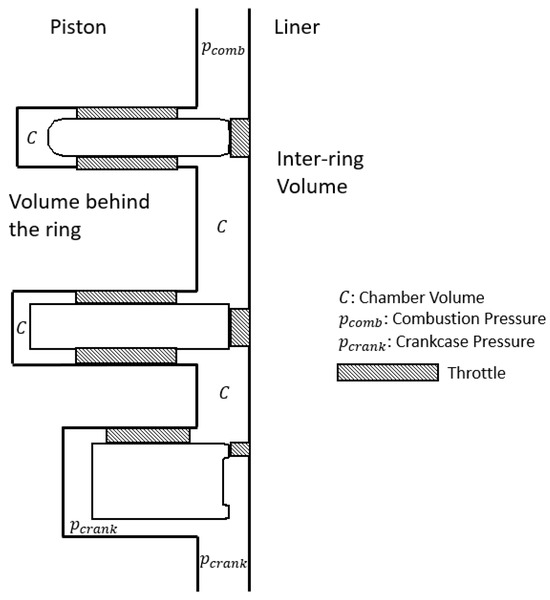
Figure 1.
Cross-section of the gas flow model for the complete ring pack.
An isothermal change in state is assumed for the gas mass flow rate in each chamber, where
where the change in mass is
and the chamber pressure is
The chamber temperature, , is calculated from the piston groove temperatures, which are assumed to be constants for the chambers behind the rings. For the top ring, the groove temperature is 170 °C; the second ring groove temperature is 140 °C, and for the oil control ring, the groove temperature is 125 °C. To find the chamber temperature at each land, the groove temperatures are interpolated linearly.
The model reported by Tian [33] is used for the gas flow at the ring end gap. This is an analytical method whereby the mass flow rate of gas at the end gap is found using
where the gas flow coefficient, and the function, are
This method is based on a differential between the upstream and downstream pressure.
7. Results and Discussion
The simulations are carried out for a single-cylinder model taken from a 1.4 L engine, with the fuel switched between gasoline and hydrogen. The detailed data, lubricant properties and material and surface properties can be found in Table 2 and Table 3.

Table 2.
Engine data.

Table 3.
Material properties and surface topographical parameters.
The combustion curves for hydrogen and gasoline at 2000 rpm and 20% load can be found in Figure 2, with 3000 rpm and 20% load in Figure 3, and the 3000 rpm and 100% load in Figure 4. The engine load refers to the actual engine output torque compared to the maximum engine output torque as a percentage for a particular operating speed. A 20% engine load can be considered as an idle condition, while a 100% engine load refers to a fully open throttle and the maximum output for the given speed condition.
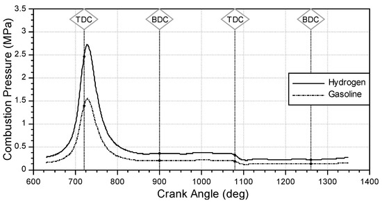
Figure 2.
Combustion pressure at 2000 rpm and 20% load.
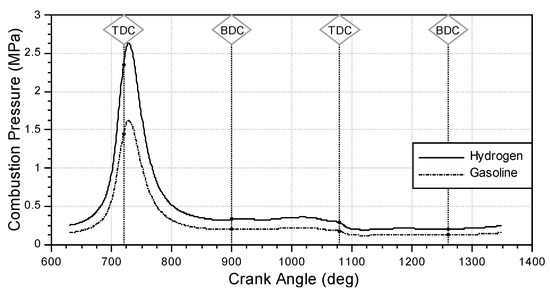
Figure 3.
Combustion pressure at 3000 rpm and 20% load.
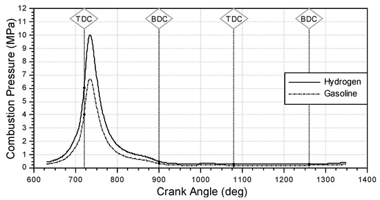
Figure 4.
Combustion pressure at 3000 rpm and 100% load.
At 2000 rpm, it can be observed that, at top dead center, the minimum oil film thickness of the gasoline engine is higher than that of the hydrogen engine (Figure 5). During the downstrokes, the minimum oil film thickness reaches a relatively steady state, even at the bottom dead center reversal point. At 3000 rpm, it can be observed in Figure 6 that, at low loads, during the downstrokes, the hydrogen engine has a higher minimum oil film thickness in the top compression ring than the gasoline engine. However, during the upstroke, the minimum film thickness is similar between the two fuels.
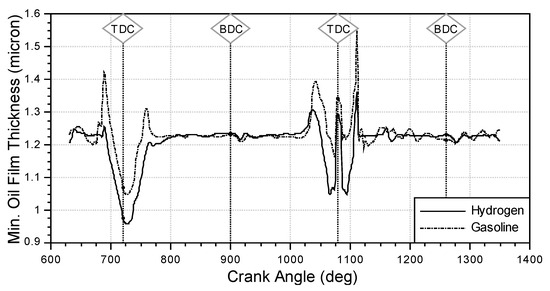
Figure 5.
Minimum oil film thickness at 2000 rpm and 20% load.
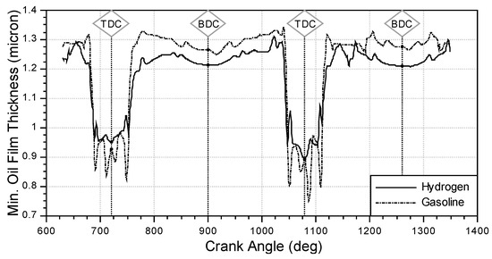
Figure 6.
Minimum oil film thickness at 3000 rpm and 20% load.
Figure 7 shows the opposite behavior to Figure 6. The hydrogen has a lower minimum oil film thickness for the top compression ring than the gasoline engine around combustion, with the biggest difference around the combustion point.
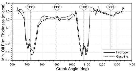
Figure 7.
Minimum oil film thickness at 3000 rpm and 100% load.
For the 20% load cases, the friction between the ring and the liner is very comparable between the hydrogen and gasoline variants, as can be observed in Figure 8 and Figure 9. Small differences can be observed in the 20% load cases around the mid-stroke for the different speeds. The difference around combustion is due to the higher combustion pressure of the hydrogen fuel. The same can also be observed for the 100% load case, with the only notable difference being at combustion (Figure 10).
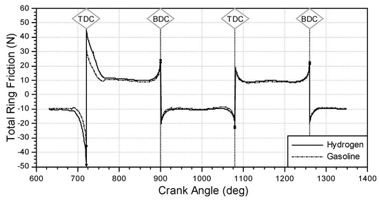
Figure 8.
Total ring friction at 2000 rpm and 20% load.
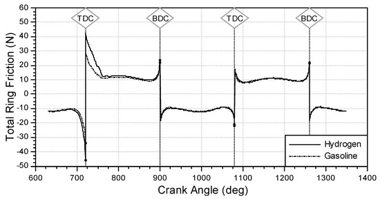
Figure 9.
Total ring friction at 3000 rpm and 20% load.
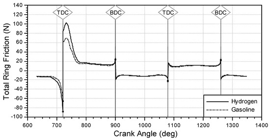
Figure 10.
Total ring friction at 3000 rpm and 100% load.
Frictional power loss can be calculated as the friction force multiplied by the piston pin velocity. Taking a look at the friction power loss for the 20% loads, Figure 11 and Figure 12 show what is expected based on the total ring friction results in Figure 8 and Figure 9. A larger friction power loss is seen for the hydrogen variant around combustion.
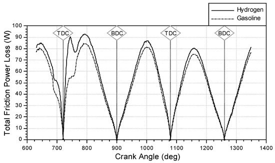
Figure 11.
Total friction power loss at 2000 rpm and 20% load.
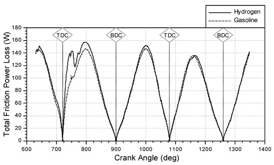
Figure 12.
Total friction power loss at 3000 rpm and 20% load.
More noticeable is the 100% load, where the hydrogen variant shows a much larger spike around the combustion point. In Figure 13, we can see an almost 200 W peak total friction power loss increase for the hydrogen variant when compared to gasoline.
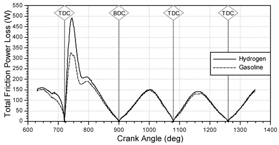
Figure 13.
Total friction power loss at 3000 rpm and 100% load.
By investigating the source of the 200 W difference observed in the 100% load case for hydrogen, it was found that the asperity power loss in the top compression ring is the cause, as can be seen in Figure 14. This is due to the metal-to-metal contact caused when entering the boundary regime of lubrication, as the asperity pressure rises (Figure 15) due to the lower minimum oil film thickness having reduced at this point, as could be observed in Figure 7.
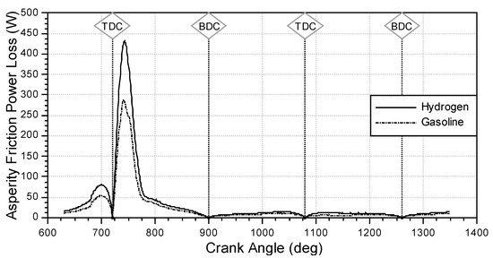
Figure 14.
Asperity power loss at 3000 rpm and 100% load.
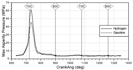
Figure 15.
Maximum asperity pressure at 3000 rpm and 100% load.
The increased asperity pressure in the case of hydrogen could also increase the amount of wear on the piston ring pack. Over prolonged running, if the hydrogen fuel removes the ring coatings and destroys the protective additives in the lubricant, as has been reported in the literature, this will also lead to increased wear, and more frequent service intervals will be required.
When inspecting the results for blow-by (Figure 16, Figure 17 and Figure 18), it can be observed for both speeds and for both the low and high loading conditions that the hydrogen variant is more susceptible than the gasoline one throughout the engine cycle. This trend matches that which has been seen in the literature [15]. Looking at the results, it can be seen that, for the 2000 rpm 20% load case, the average amount of blow-by for hydrogen is 5 and the gasoline has . This means that the hydrogen-fueled engine would have 22% more blow-by over the course of an engine cycle.
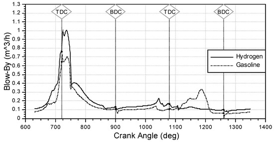
Figure 16.
Blow-by at 2000 rpm and 20% load.
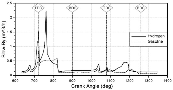
Figure 17.
Blow-by at 3000 rpm and 20% load.
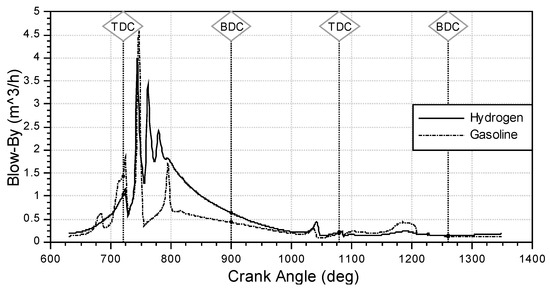
Figure 18.
Blow-by at 3000 rpm and 100% load.
For the 3000 rpm and 20% load case, the hydrogen has an average blow-by per engine cycle of and the gasoline has . This is more than a 50% increase over the course of an engine cycle. Similar trends are also observed in the 3000 rpm and 100% loading condition, where the average blow-by of the hydrogen variant is and for gasoline it is , again showing an increase by 40% across the engine cycle.
It is interesting to note in the results for the 100% loading condition that the peak blow-by of the gasoline variant is slightly higher than that of hydrogen. Although both fuel types have their peaks at combustion, the hydrogen variant also exhibits larger amounts of blow-by all through the expansion stroke. With continuous operation, this higher blow-by could lead to the reported effects of the hydrogen embrittlement of engine components, causing damage to the crank case or reducing the effects of coatings on the ring as well as destroying the lubricating properties and additives in the lubricant.
8. Concluding Remarks
A simulation model has been presented for an ICE and results have been presented for two fuel types, gasoline and hydrogen. The model was simulated for 2000 rpm at low load and 3000 rpm at high and low engine loading conditions. It was observed that the hydrogen variant of the model had both higher frictional power losses and blow-by in all cases, thus matching the trends reported in field testing that have been reported in the literature. It was also observed that the hydrogen variants exhibited more blow-by throughout the engine cycle, particularly in the expansion stroke, not just at combustion, where the difference between the in-cylinder pressure was greatest due to the higher flame speeds and burn rates required for hydrogen. If such behavior occurs in the field, it can lead to severe problems regarding the overall performance and lifetime of the engine due to unwanted side effects like lubricant degradation, leading to a loss of efficiency and hydrogen embrittlement which, if severe enough, could cause the complete failure of the engine and its components. This is especially important, as nickel, titanium and their corresponding alloys are some of the most susceptible materials to hydrogen embrittlement and they have been some of the most common coatings used in piston ring manufacture in recent times. As a result, it will be necessary to develop new ring geometries, coatings and lubrication methods to provide a more suitable sealing of the ring pack, which can be used in future hydrogen ICEs.
Author Contributions
Methodology, S.R.B.; Software, S.R.B. and G.O.; Formal analysis, S.R.B.; Investigation, S.R.B.; Writing—original draft, S.R.B. and G.O.; Writing—review & editing, S.R.B. and G.O.; Supervision, G.O. All authors have read and agreed to the published version of the manuscript.
Funding
This research received no external funding.
Data Availability Statement
The data presented in this study are available on request from the corresponding author.
Conflicts of Interest
The authors declare no potential conflict of interest with respect to the research, authorship and/or publication of this article.
Nomenclature
| Friction constants set to 2.718, 1000 and 1000, respectively | |
| Apparent contact area | |
| Cross-sectional area of gas flow | |
| Gas flow coefficient for ring end gap | |
| Composite Young’s modulus of elasticity | |
| Ring friction | |
| Boundary friction | |
| Function of gas mass flow | |
| Viscous friction | |
| Statistical function | |
| Lubricant film thickness | |
| Averaged lubricant film thickness | |
| Isentropic gas exponent | |
| Lubrication number (duty parameter) | |
| Reference length | |
| Gas mass flowrate | |
| Gas mass flowrate at ring end gap | |
| Change in gas mass | |
| Contact pressure | |
| Initial chamber pressure depending on stroke direction | |
| Asperity pressure | |
| Combustion pressure | |
| Crankcase pressure | |
| Chamber pressure | |
| Downstream pressure | |
| Pressure in the direction of lubricant film thickness | |
| Upstream pressure | |
| Pressure in the direction along the liner height | |
| Averaged pressure | |
| Asperity contact ratio | |
| Gas constant | |
| Time | |
| Lubricant oil temperature | |
| Chamber temperature | |
| Upstream temperature | |
| Sliding speed of surfaces 1 and 2 in direction | |
| Difference in sliding speed of surfaces 1 and 2 in direction | |
| Direction along the liner height | |
| Greek Symbols | |
| Asperity mean summit radius | |
| Number of asperities per unit area of contact | |
| Lubricant dynamic viscosity | |
| Fill ratio in Reynolds equation | |
| Asperity shear stress | |
| Dimensionless clearance height | |
| Friction coefficient | |
| Abrasive friction coefficient | |
| Adhesive friction coefficient | |
| Lubricant density | |
| Surface roughness (r.m.s.) | |
| Combined shear flow factor | |
| Pressure flow factor in direction | |
| Gas flow coefficient for orifice flow | |
References
- King, J. The King Review of Low-Carbon Cars: Part 1: The Potential for CO2 Reduction; Office of Public Sector Information, HM Treasury, HMSO: Richmond, UK, 2007. [Google Scholar]
- Capros, P.; De Vita, A.; Tasios, N.; Papadopoulos, D.; Siskos, P.; Apostolaki, E.; Zamapara, M.; Paroussos, L.; Fragiadakis, K.; Kouvaritakis, N.; et al. EU Energy, Transport and GHG Emissions—Trends to 2050. In European Commission, Directorate-General for Energy, Directorate-General for Climate Action and Directorate-General for Mobility and Transport; EU Publications: Luxembourg, 2013. [Google Scholar]
- Onorati, A.; Payri, R.; Vaglieco, B.M.; Agarwal, A.K.; Bae, C.; Bruneaux, G.; Canakci, M.; Gavaises, M.; Günthner, M.; Hasse, C.; et al. The role of hydrogen for future internal combustion engines. Int. J. Engine Res. 2022, 23, 529–540. [Google Scholar] [CrossRef]
- Ogden, J.M. Prospects for Building a Hydrogen Energy Infrastructure. Annu. Rev. Energy Environ. 1999, 24, 227–279. [Google Scholar] [CrossRef]
- Bockris, J.O. A Hydrogen Economy. In Comprehensive Treatise of Electrochemistry; Plenum Press: New York, NY, USA, 1981; pp. 505–526. [Google Scholar]
- Du, H.; Chen, Z.; Peng, B.; Southworth, F.; Ma, S.; Wang, Y. What drives CO2 emissions from the transport sector? A linkage analysis. Energy 2019, 175, 195–204. [Google Scholar] [CrossRef]
- Wróbel, K.; Wróbel, J.; Tokarz, W.; Lach, J.; Podsadni, K.; Czerwiński, A. Hydrogen Internal Combustion Engine Vehicles: A Review. Energies 2022, 15, 8937. [Google Scholar] [CrossRef]
- Sopena, C.; Diéguez, P.M.; Sáinz, D.; Urroz, J.C.; Guelbenzu, E.; Gandía, L.M. Conversion of a commercial spark ignition engine to run on hydrogen: Performance comparison using hydrogen and gasoline. Int. J. Hydrogen Energy 2010, 35, 1420–1429. [Google Scholar] [CrossRef]
- Sun, D.; Liu, F. Research on the Performance and Emission of a Port Fuel Injection Hydrogen Internal Combustion Engine. In Proceedings of the 2011 International Conference on Computer Distributed Control and Intelligent Environmental Monitoring, Changcha, China, 19–20 February 2011; pp. 963–966. [Google Scholar]
- Verhelst, S.; Sierens, R.; Verstraeten, S. A Critical Review of Experimental Research on Hydrogen Fueled SI Engines; Technical Paper 2006-01-0430; SAE: Warrendale, PA, USA, 2006; Volume 115, pp. 264–274. [Google Scholar]
- Verhelst, S.; Wallner, T. Hydrogen-fueled internal combustion engines. Prog. Energy Combust. Sci. 2009, 35, 490–527. [Google Scholar] [CrossRef]
- Stone, R. Introduction to Internal Combustion Engines; Springer: London, UK, 1999; Volume 3, pp. 1–16. [Google Scholar]
- Turner, J.W.G.; Popplewell, A.; Patel, R.; Johnson, T.R.; Darnton, N.J.; Richardson, S.; Bredda, S.W.; Tudor, R.J.; Bithell, C.I.; Jackson, R.; et al. Ultra Boost for Economy: Extending the Limits of Extreme Engine Downsizing. SAE Int. J. Engines 2014, 7, 387–417. [Google Scholar] [CrossRef]
- Lee, J.; Park, C.; Kim, Y.; Choi, Y.; Bae, J.; Lim, B. Effect of turbocharger on performance and thermal efficiency of hydrogen-fueled spark ignition engine. Int. J. Hydrogen Energy 2019, 44, 4350–4360. [Google Scholar] [CrossRef]
- Verhelst, S.; Sierens, R. Hydrogen engine-specific properties. Int. J. Hydrogen Energy 2001, 26, 987–990. [Google Scholar] [CrossRef]
- Allen, E.; Questa, H.; Walker, J.; Mohammadpour, M.; Bewsher, S.R.; Offner, G. Simulating the tribological performance of new water-based and mineral-oil-based lubricants for a journal bearing within an electrified powertrain. In Proceedings of the ÖTG-Symposium 2022, Wiener Neustadt, Austria, 15 September 2022. [Google Scholar]
- Wróblewski, P. Investigation of energy losses of the internal combustion engine taking into account the correlation of the hydrophobic and hydrophilic. Energy 2023, 264, 126002. [Google Scholar] [CrossRef]
- Dziubak, T.; Dziubak, S.D. A study on the effect of inlet air pollution on the engine component wear and operation. Energies 2022, 15, 1182. [Google Scholar] [CrossRef]
- Oh, S.; Park, C.; Nguyen, D.; Kim, S.; Kim, Y.; Choi, Y.; Lee, J. Investigation on the operable range and idle condition of hydrogen-fueled spark ignition engine for unmanned aerial vehicle (UAV). Energy 2021, 237, 121645. [Google Scholar] [CrossRef]
- Barthélémy, H. Compatibility of Metallic Materials with Hydrogen—Review of the present knowledge. In Proceedings of the 16th World Hydrogen Energy Conference, Lyon, France, 13–16 June 2006. [Google Scholar]
- Offner, G.; Knaus, O. A generic friction model for radial slider bearing simulation considering elastic and plastic deformation. Lubricants 2015, 3, 522–538. [Google Scholar] [CrossRef]
- AVL List GmbH. AVL List GmbH: AVL EXCITE Piston & Rings Theory: Version 2023; Software Documentation; AVL List GmbH: Graz, Austria, 2023. [Google Scholar]
- Herbst, H.; Priebsch, H. Simulation of piston ring dynamics and their effect on oil consumption. SAE Trans. 2000, 109, 862–873. [Google Scholar]
- Priebsch, H.-H.; Herbst, H.M. Simulation of Effects of Piston Ring Parameters on Ring Movement, Friction, Blow-by and LOC. MTZ Mot. Z. 1999, 60, 772–779. [Google Scholar]
- Götze, A.; Jaitner, D. Combined experimental and simulative approach for friction loss optimization od DLC coated piston rings. Automot. Engine Technol. 2022, 7, 283–293. [Google Scholar] [CrossRef]
- Mahmoud, K.G.; Knaus, O.; Parikyan, T.; Offner, G.; Sklepic, S. An integrated model for the performance of piston ring pack in internal combustion engines. Proc. Inst. Mech. Eng. Part K J. Multi-Body Dyn. 2018, 232, 371–384. [Google Scholar] [CrossRef]
- Patir, N.; Cheng, H.S. An Average Flow Model for Determining Effects of Three-Dimensional Roughness on Partial Hydrodynamic Lubrication. J. Lubr. Technol. 1978, 100, 12–17. [Google Scholar] [CrossRef]
- Patir, N.; Cheng, H.S. Application of average flow model to lubrication between rough sliding surfaces. J. Lubr. Technol. 1979, 101, 220–229. [Google Scholar] [CrossRef]
- Jakobsson, B.; Floberg, L. The Finite Journal Bearing Considering Vaporization; Transactions of Chalmers University of Technology: Gothenburg, Sweden, 1957; Volume 190, pp. 1–116. [Google Scholar]
- Olsson, K.O. Cavitation in Dynamically Loaded Bearings; Transactions of Chalmers University of Technology: Gothenburg, Sweden, 1965; Volume 308. [Google Scholar]
- Greenwood, J.A.; Tripp, J.H. The elastic contact of rough spheres. J. Appl. Mech. 1967, 34, 153–159. [Google Scholar] [CrossRef]
- Greenwood, J.A.; Tripp, J.H. The contact of two nominally flat rough surfaces. Proc. IMechE 1970, 185, 625–634. [Google Scholar] [CrossRef]
- Tian, T. Modeling the Performance of the Piston Ring-Pack in Internal Combustion Engines. Ph.D. Thesis, Massachusetts Institute of Technology, Cambridge, MA, USA, 1997. [Google Scholar]
Disclaimer/Publisher’s Note: The statements, opinions and data contained in all publications are solely those of the individual author(s) and contributor(s) and not of MDPI and/or the editor(s). MDPI and/or the editor(s) disclaim responsibility for any injury to people or property resulting from any ideas, methods, instructions or products referred to in the content. |
© 2023 by the authors. Licensee MDPI, Basel, Switzerland. This article is an open access article distributed under the terms and conditions of the Creative Commons Attribution (CC BY) license (https://creativecommons.org/licenses/by/4.0/).