Abstract
Tool wear behavior is mainly influenced by cutting parameters for a given tool–workpiece pair and cutting process. Rapid tool wear increases production costs and deteriorates machining quality in manufacturing industries. Inconel 718 is prone to severe tool wear in the milling process due to its high strength under elevated temperature and being prone to work hardening. The effects of cutting speed and feed rate on the tool chipping mechanism and tool wear multi-patterns in face milling Inconel 718 with cemented carbide tools are investigated in this research. Firstly, the face milling experiments of Inconel 718 were conducted with various cutting speeds and feed rates. The experimental results show that the tool wear morphology, especially the tool edge chipping on the flank face, is changed with the cutting parameters. Secondly, the tool chipping mechanism in the milling process is discussed. The effects of cutting speed and feed rate on the chipping and wear patterns of cutting tools are clarified. Finally, the ANOVA analysis is conducted to verify the effects of cutting parameters on cutting force, tool life, and tool edge chipping. This work provides an experimental basis for process parameter optimization to alleviate cutting tool wear in machining processes.
1. Introduction
Inconel 718 has extensive applications in aerospace industries because of its corrosion resistance and high oxidation resistance at high temperatures [1,2]. However, the high strength and low thermal conductivity of Inconel 718 lead to severe tool wear during machining processes [3,4,5]. Cemented carbide tools are considered promising candidates in cutting operations for nickel-based alloys due to their high hardness and excellent thermomechanical properties. Severe tool wear of cemented carbide inserts is an urgent problem in realizing the high-efficiency machining of nickel-based alloys [6].
Intense workpiece material deformation and severe friction on the tool–workpiece interface are involved in the metal cutting process. In recent years, dry cutting has been used to achieve cleaner production [7,8]. Rapid tool failure is triggered by drastic friction and large temperature gradients on the tool–workpiece interface in dry cutting. The tool wear on the flank face also affects the machined surface quality and machining accuracy [9]. Cutting parameters, cooling conditions, and tool geometry are regarded as the factors that affect tool wear and tool failure, while the cutting parameters have been recognized as the main factors [10].
Several researchers studied the tool wear patterns in machining nickel-based alloy Inconel 718 by using cemented carbide and ceramic cutting tools. Bhatt et al. [7] found that adhesive wear and abrasive wear were dominant wear patterns during finish turning Inconel 718. Imran et al. [11] compared abrasion, adhesion, diffusion, and chipping in dry cutting and wet cutting of Inconel 718. They found severe element diffusion occurred under dry cutting conditions. Hao et al. [12] reported that the intense element diffusion and oxidation during the dry cutting of Inconel 718 was the main reason for tool wear (vc = 20–45 m/min). Alagan et al. [13] observed that cracks propagated with an increase in cutting speed in turning Inconel 718. They found that the cracking of the tool caused drastic tool wear in high-speed turning. These results on tool wear mechanisms are limited to continuous cutting without considering interrupted cutting effects.
Interrupted cutting leads to alternating force and thermal shocks on the tool–workpiece and tool–chip contact interfaces [14,15]. The tool wear and chipping of the cutting edge are related to these shocks. Ma et al. [16] and Yu et al. [17] found that there are obvious micro-cracks and dislocations on the flank face in interrupted cutting Inconel 718. Banda et al. [18] investigated the wear progression of micro-cracks with different cutting parameters in milling Inconel 718. Such a failure mode is attributed to alternating force and thermal shocks, which are considerable in milling Inconel 718. The effect of cutting parameters on tool wear in turning has been studied in recent years [19,20]. However, the mechanism of tool edge chipping in interrupted cutting and the effects of cutting speed and feed rate on tool edge chipping are still poorly illustrated.
More research about the tool wear mechanism in the milling process has emerged in recent years. Li et al. [21] found that the instantaneous high thermal and mechanical stresses applied to the inserts were the reason for the rapid tool wear in the high-speed face milling process. Jiang et al. [22] investigated tool wear behavior in end milling and found that there was severe edge chipping on the cutting edge. The edge chipping would be observed on the worn tool. Halim et al. [23] observed that the chipping was generated during the development of tool wear in milling Inconel 718. However, the formation mechanism of edge chipping was barely explained. The mechanism of edge chipping in face milling nickel-based superalloy is required to be further explained.
The objective of this research is to investigate the effects of cutting speed and feed rate on tool edge chipping mechanism and multiple tool wear patterns in face milling Inconel 718 with carbide tools. Face milling experiments at different cutting parameters were conducted to measure tool wear morphology, tool life, and cutting force. The tool wear mechanism at different cutting parameters is discussed. Statistical analyses are performed to evaluate the effects of cutting speed and feed rate on tool life, cutting force, and tool edge chipping. Furthermore, the relationship between the cutting force and tool wear evolution on the flank face is analyzed.
2. Materials and Experiments
Forged Inconel 718 was used as the workpiece material. The chemical composition and mechanical properties of Inconel 718 obtained from a material supplier are shown in Table 1 and Table 2, respectively.

Table 1.
Chemical compositions of Inconel 718.
Table 2.
Physical–mechanical properties of Inconel 718.
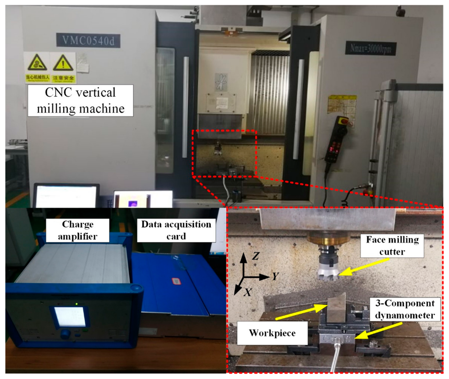
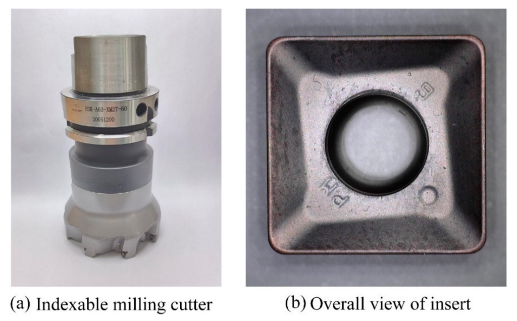
The experimental setup is shown in Figure 1. Face milling of Inconel 718 was conducted on a VMC0540d CNC vertical milling machine with cemented carbide inserts under a dry machining environment. The indexable face milling cutter (diameter D = 80 mm, maximum number of teeth z = 8) provided by cutting tool supplier ZCC·CT was used in the experiments, as shown in Figure 2. The milling experiment was conducted by applying one tooth to the cutter. A TiAlN-coated WC-Co cemented carbide insert with 0.8 mm tool nose radius was selected for experiments. The effective rake, clearance, and inclination angle were −15°, 5°, and 0°, respectively.

Figure 1.
Face milling experiments.
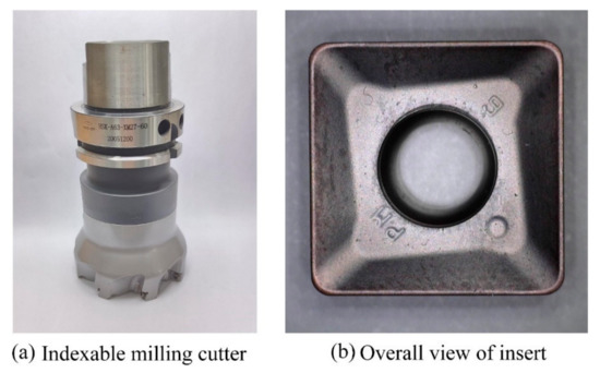
Figure 2.
Overall view of face milling cutter and insert.
The experiments were carried out with different cutting speeds and feed rates. The cutting depth was kept constant at 0.2 mm. The applied range of the cutting parameters (cutting speed vc = 45 m/min–75 m/min, feed rate per tooth fz = 0.05 mm/r–0.15 mm/r) was recommended by the technical support of cutting tool supplier ZCC·CT. The cutting parameters used in this study are shown in Table 3.
Table 3.
Cutting conditions for tool wear test.
The cutting force measurement system was composed of a Kistler 9129AA 3-component dynamometer, charge amplifier, and data acquisition card. The maximum flank wear width VB was measured with a Dino-Lite AM-413TL optical microscope every 20 s in each cutting condition until the 300 μm flank wear width (ISO-8688) was reached. A scanning electron microscope (SEM, JMS-7610F) equipped with energy-dispersive spectroscopy (EDS) was used to analyze the tool wear morphology and chemical compositions.
3. Results and Discussion
3.1. Cutting Forces
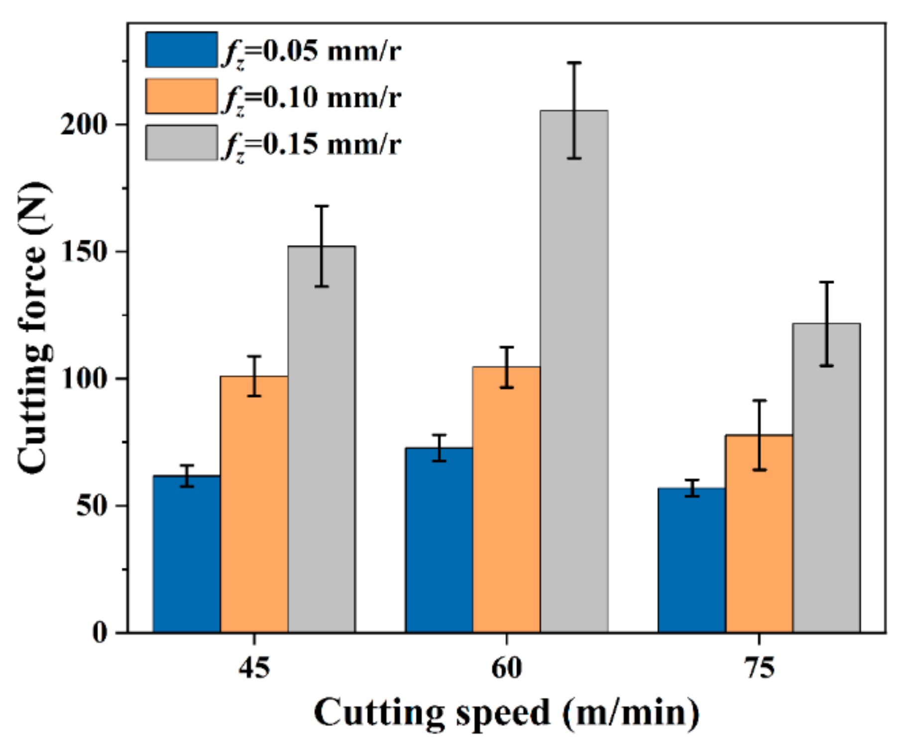
The resultant cutting forces of the new inserts at different cutting parameters are shown in Figure 3. The resultant cutting force of 152.1 N is observed at the cutting speed of 45 m/min and the feed rate of 0.15 mm/r, whereas the resultant cutting force is 61.7 N at the feed of 0.05 mm/r. It can be seen that the resultant cutting force increases with the increase in the feed rate. The same trend can be found at cutting speeds of 60 m/min and 75 m/min. This is because the variation in undeformed chip thickness at different feed rates has an effect on cutting force [24].

Figure 3.
Cutting force at different cutting parameters with new inserts.
However, the effect of cutting speed on resultant cutting force is found to be different from that of feed rate. The maximum value of resultant cutting forces of new inserts in every feed rate is achieved at the cutting speed of 60 m/min. The variation of cutting force is generated due to the change in the build-up edge and adhesion layer observed on the flank face in the milling process. The effective rake angle is added due to the generation of the build-up edge as the cutting speed increases. It results in an increase in the cutting force on the one hand. On the other hand, the temperature generation rate becomes higher at a higher cutting speed, which makes workpiece material soft [25]. It leads to a reduction in cutting force at a higher cutting speed. The variation of cutting force with cutting speed is attributed to these two factors.
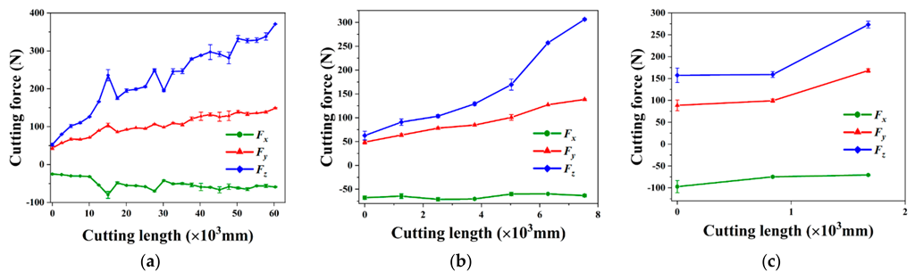
The evolution of cutting force over cutting length at the cutting speed of 60 m/min with different feed rates in milling Inconel 718 is shown in Figure 4. The force components, including feed force (Fx), tangential force (Fy), and axial force (Fz), force were measured with a dynamometer during each test until the critical flank wear width of 300 μm was reached. It can be seen that all three cutting force components increase with the cutting length. The Fx is observed to be almost constant over cutting length under the feed rates of 0.10 mm/r and 0.15 mm/r. The average growth rate of Fz 5.27 N/m is obtained at the feed rate of 0.05 mm/r. Such an evolution trend is observed in the cutting force component Fy. However, the average growth rate of Fy is 1.745 N/m, which is much smaller than Fz at the feed of 0.05 mm/r.
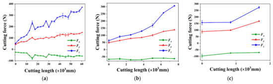
Figure 4.
Cutting forces vs. cutting length at vc = 60 m/min and (a) fz = 0.05 mm/r, (b) fz = 0.10 mm/r, and (c) fz = 0.15 mm/r.
The axial force Fz is observed as the largest of the three force components, while the feed force Fx is minimum. The pressure and friction between the workpiece and the negative chamfer render the Fz larger than the other components. The maximum Fz value of 370 N is measured at the feed rate of 0.05 mm/r and cutting speed of 60 m/min, while the maximum value of Fz at the feed rate of 0.15 mm/r and the cutting speed of 75 m/min is less than 250 N. The worn-out inserts are subjected to higher temperatures at larger cutting parameters, which is similar to the new inserts. Small cutting forces are obtained under the cutting speed of 75 m/min from both the new insert and worn-out insert.
The interaction between tool wear and cutting forces is shown in Figure 5. The friction behavior and the tool–workpiece contact condition are affected by the evolution of tool wear [26]. The evolution of cutting force is affected by the increase in contact area on the tool–workpiece interface induced by tool wear. Then the increase in cutting force results in an increase in the normal stress on the flank face, which further aggravates tool wear. The relationship between cutting force and tool wear width on the flank face at the cutting speed of 45 m/min and the feed rate of 0.5 mm/r is shown in Figure 5a, with the correlation coefficient of 0.9377. The correlation coefficient R values for the rest of the test are shown in Figure 5b. The values of the correlation coefficient R between tool wear and cutting force in each test group are all over 0.9. This indicates that the tool wear and cutting force are linear in the milling process.
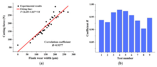
Figure 5.
(a) Cutting force vs. tool flank wear width at vc = 45 m/min and fz = 0.05 mm/r; (b) correlation coefficients at other cutting parameters as shown in Table 3.
3.2. Tool Wear Progress and Tool Worn Surface Morphology
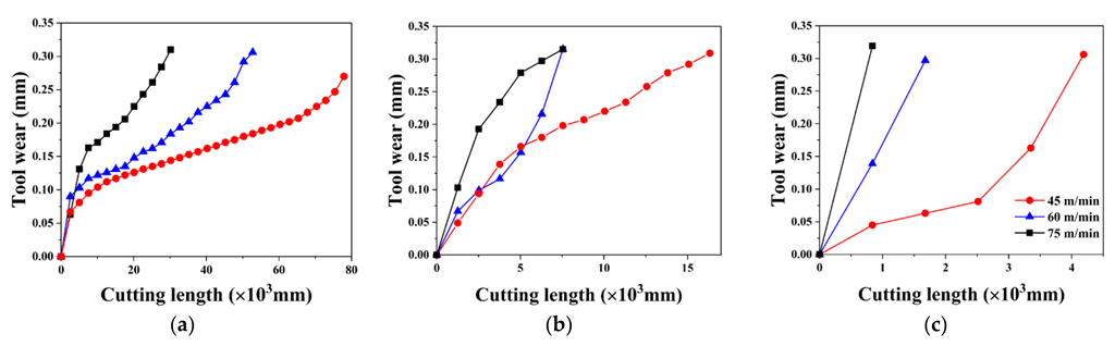
The flank wear curves of the coated carbide insert in face milling Inconel 718 under different cutting parameters are shown in Figure 6. The evolution of tool wear can be observed with an initial wear stage followed by a steady wear stage. A significant increase in the tool wear rate after the tool wear reaches a certain level is called the failure region. However, the failure region is less obvious at the larger cutting parameters. This is because the tool insert is worn out before the rapid wear occurs.

Figure 6.
Tool wear progress curves at (a) fz = 0.05 mm/r, (b) fz = 0.10 mm/r, and (c) fz = 0.15 mm/r.
The effect of cutting parameters on the tool wear evolution can be characterized by tool life. The carbide inserts wear faster when cutting parameters become larger. The tool life is reduced by 63% as cutting speed increases from 45 m/min to 75 m/min, whereas the tool life is reduced by 84% as feed increases from 0.05 mm/r to 0.15 mm/r. The effect of feed on tool life appears more significant under experimental conditions.
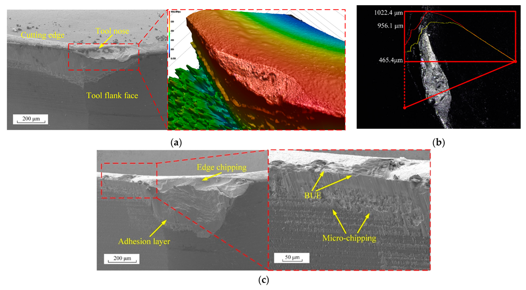
The tool wear morphology in milling Inconel 718 with a TiAlN-coated WC-Co cemented carbide insert is shown in Figure 7. The tool damage and failure modes can be classified into flank wear and tool edge chipping. The flank wear region is located at the tool nose under the experimental conditions. The tool wear patterns present different characteristics in different positions of the wear area, as shown in Figure 7a,c. The tool edge chippings caused by dramatic loads and the built-up edge appear on the flank face near the cutting edge. Traces of the adhesive layer and notching can be found on the flank face.
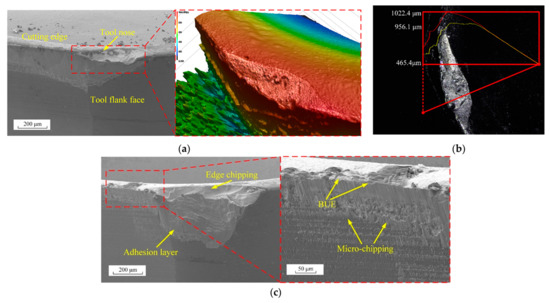
Figure 7.
Tool worn surface morphology under VB = 300 μm for (a,b) vc = 45 m/min and fz = 0.05 mm/r and (c) vc = 60 m/min and fz = 0.05 mm/r.
In addition, different features of wear morphology are presented with the feed rate increasing. As shown in Figure 7c, a large adhesive layer can be found on the flank face at the feed of 0.15 mm/r. The wear area caused by the tool edge chippings with the feed rate of 0.15 mm/r is larger than that with the feed rate of 0.05 mm/r. This indicates that the change in tool wear morphology is affected by the cutting parameters.
3.3. Tool Wear Multi-Patterns
The tool wear morphology is characterized by the tool wear patterns, which are affected by cutting parameters. The detailed information provided by SEM and EDS images is analyzed to determine the wear patterns of the worn inserts.
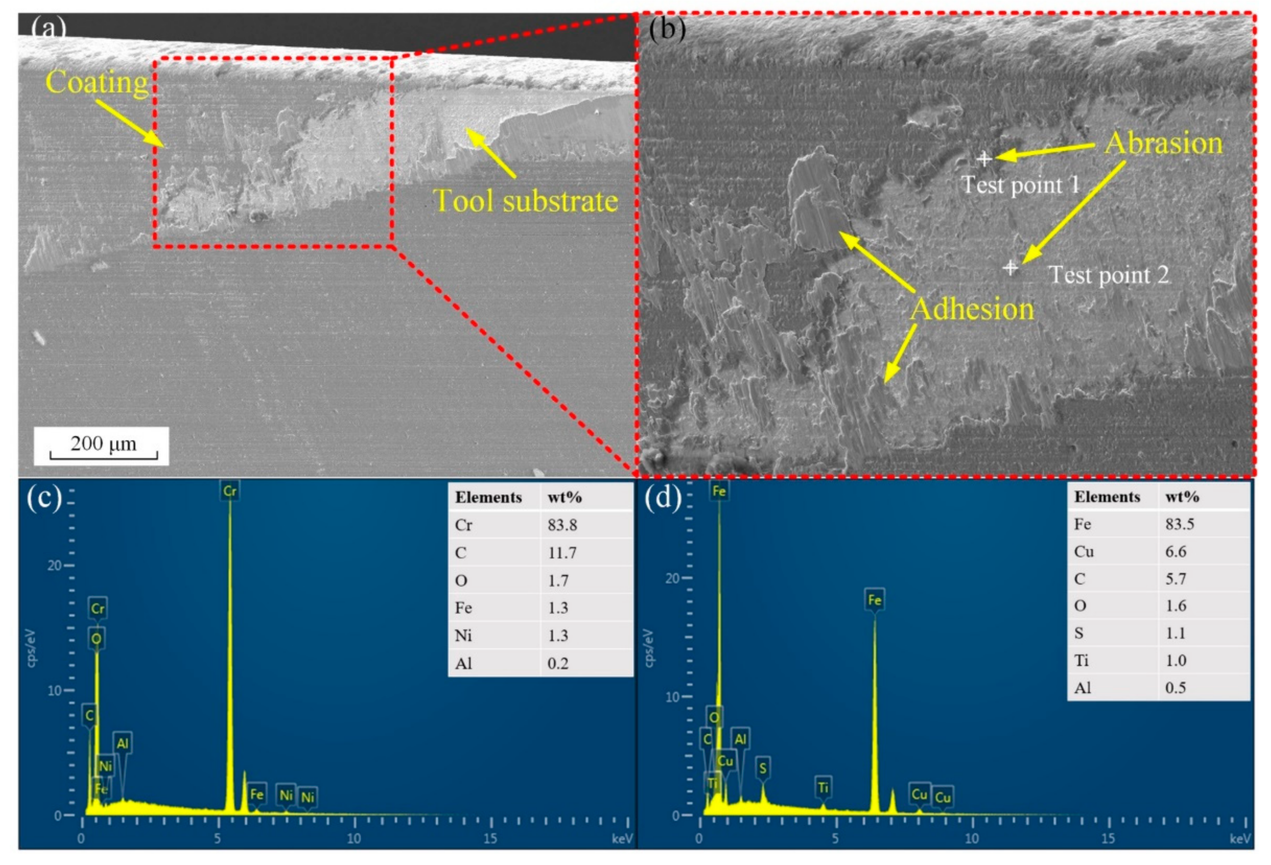
The effect of cutting parameters on abrasive wear and adhesive wear is shown in Figure 8. Multiple parallel marks on the flank face are the result of abrasion scraping. High-hardness particles are exposed to the surface and form abrasions due to high temperature and high pressure [7], which are likely to damage the flank face. The EDS results in Figure 8c,d show that the chemical compositions of abrasives are Cr and Fe carbides. These abrasives are the impurities caused by the precipitation of Cr and Fe elements during the heating and cooling process of workpiece forging [27].

Figure 8.
(a,b) Tool flank wear morphology at fz = 0.05 mm/r and vc = 75 m/min and (c,d) chemical compositions at Test point 1 and Test point 2, respectively.
Inconel 718 adheres to the tool substrate under high stress and temperature in the cutting process. The adhesion layer is composed of lamellar adhesion material as shown in Figure 9, which indicates that the workpiece material adheres to the flank face layer by layer. The formation and peeling of the adhesive layer reach the stable state under suitable temperature and shear strain rate conditions [28]. The stable adhesion layer is concentrated on the flank face near the tool nose as shown in Figure 9. The different characteristics of the adhesion layer and abrasive marks are shown at the given cutting parameters in face milling Inconel 718. The width of abrasive marks on the flank face can be considered as a feature of abrasive wear.
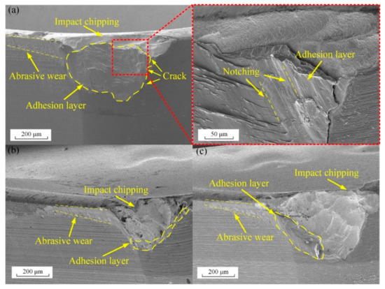
Figure 9.
SEM images of Inconel 718 adhesion layer on tool surface at feed rate of (a) 0.05 mm/r, (b) 0.10 mm/r, and (c) 0.15 mm/r.
The SEM images on the flank face at the cutting speed of 45 m/min and various feed rates are shown in Figure 9. The width of abrasive marks on the flank face reduces as the feed rate increases from 0.05 mm/r to 0.15 mm/r as shown in Figure 9. The area of the adhesion layer reduces as the feed rate increases from 0.05mm/r to 0.15 mm/r. The minimum proportion of adhesion layer in the flank wear region is observed in Figure 9c at the feed rate of 0.15 mm/r. The maximum cutting force is measured at the feed rate of 0.15 mm/r according to Figure 3. The larger alternating force at the feed rate of 0.15 mm/r in the milling process results in a reduction in the adhesive layer.
The effects of the cutting speeds on abrasive wear and adhesive wear are shown in Figure 10. The minimum width of abrasive marks is generated at the cutting speed of 60 m/min as shown in Figure 10b. However, the maximum adhesion layer can be found on the flank face at the cutting speed of 60 m/min. Cracks are observed at the edge of the adhesion layer in Figure 9a and Figure 10b. This indicates that the adhered material is unstable at these cutting parameters.
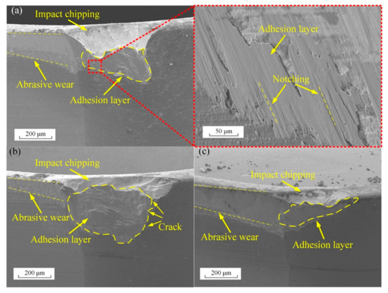
Figure 10.
SEM images of Inconel 718 adhesion layer on tool surface at the cutting speed of (a) 45 m/min, (b) 60 m/min, and (c) 75 m/min.
Traces of abrasive are also found on the adhesion layer in Figure 9a and Figure 10a. This indicates that intense friction occurs on the interface of the adhesive layer and workpiece. The adhesion layer replaces the tool substrate to interact with the workpiece material. The tool substrate is protected by the stable adhesion layer, which extends the tool life [29]. However, the tool wear is accelerated by the peeling of the unstable adhesion layer in the milling process.
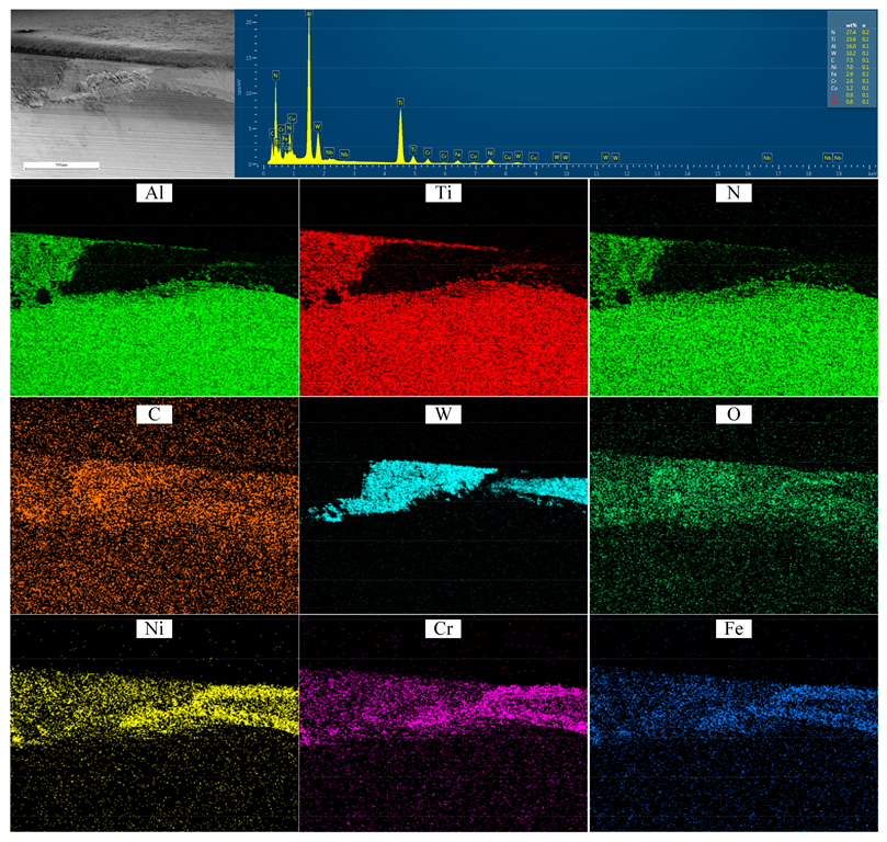
The element distribution on the worn surface was obtained by EDS mapping, as shown in Figure 11. The distribution of C and W is detected on the wear area, which indicates that the tool substrate is exposed on the worn flank face. The distribution Ni, Cr, and Fe is detected on the wear area on the flank face. In addition, the distribution of oxygen also appears on the flank face. It can be inferred that intense oxidation reactions occur on the worn surface.
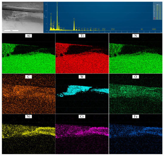
Figure 11.
EDS mapping on tool worn flank face.
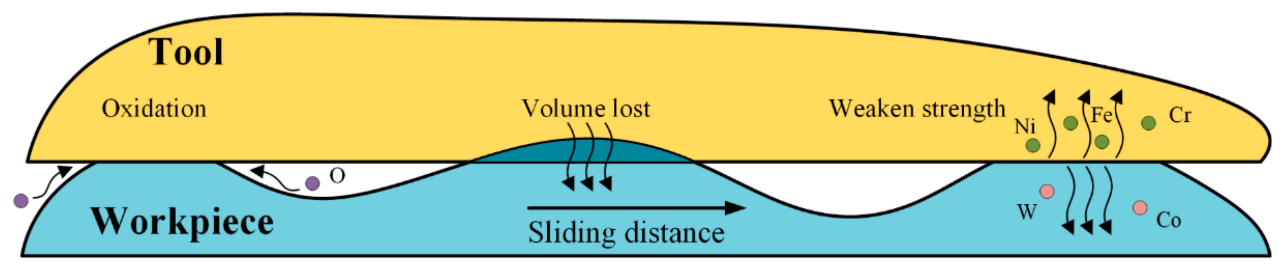
The process of diffusion wear is presented in the schematic in Figure 12 drawn by the authors. The contact interface between tool and workpiece material consists of mechanical and chemical bonding. The diffusion of elements through the contact interface is caused by the element concentration gradient and the high temperature. Intense oxidation reactions occur on the tool–workpiece interface. Therefore, the effect of diffusion and oxidation on tool wear can be classified into strength weakening, volume loss, and oxidation.

Figure 12.
Tool wear progress with diffusion and oxidation.
3.4. Tool Edge Chipping Wear Mechanism
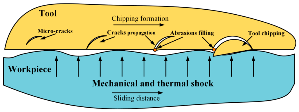
The failure of a cutting tool in machining Inconel 718 is caused by tool edge chipping together with flank wear [30]. The tool edge chipping plays a considerable role in tool failure due to the large area of this wear morphology on the flank face. The formation process of this wear pattern is shown in Figure 13 drawn by the authors. The micro-cracks and dislocation on the tool sub-surface layer are joined together under mechanical and thermal shock in milling. Cracks can be observed on the tool surface when the cracks propagate to the tool surface. The abrasions fill the cracks, leading to the further propagation of the cracks. The tool substrate is damaged by the generating and peeling of the lamellar chipping as the cutting process continues.
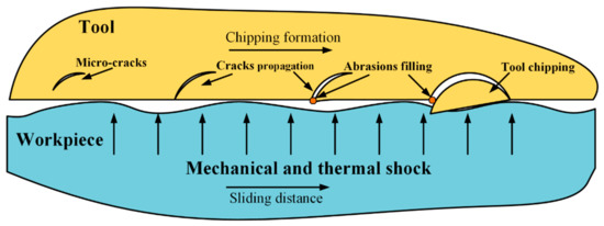
Figure 13.
Tool chipping formation due to mechanical and thermal shock.
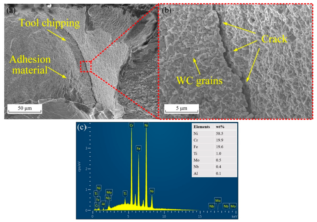
Evidence of crack propagation and peeling can be found on the worn surface at all cutting parameters in experimental conditions according to the tool wear morphology in Figure 14. The fracture-like appearance with the grain exposure is observed at the tool edge chipping surface. Some of the grains are covered with adhesion material as shown in Figure 14a,c. This indicates that the worn surface is under intense friction against the workpiece material. Additionally, it can be seen that micro-cracks propagate to the surface of tool edge chipping.

Figure 14.
SEM image of micro-crack propagations under tool surface with (a) low and (b) high magnifications, and (c) EDS results of adhesion material.
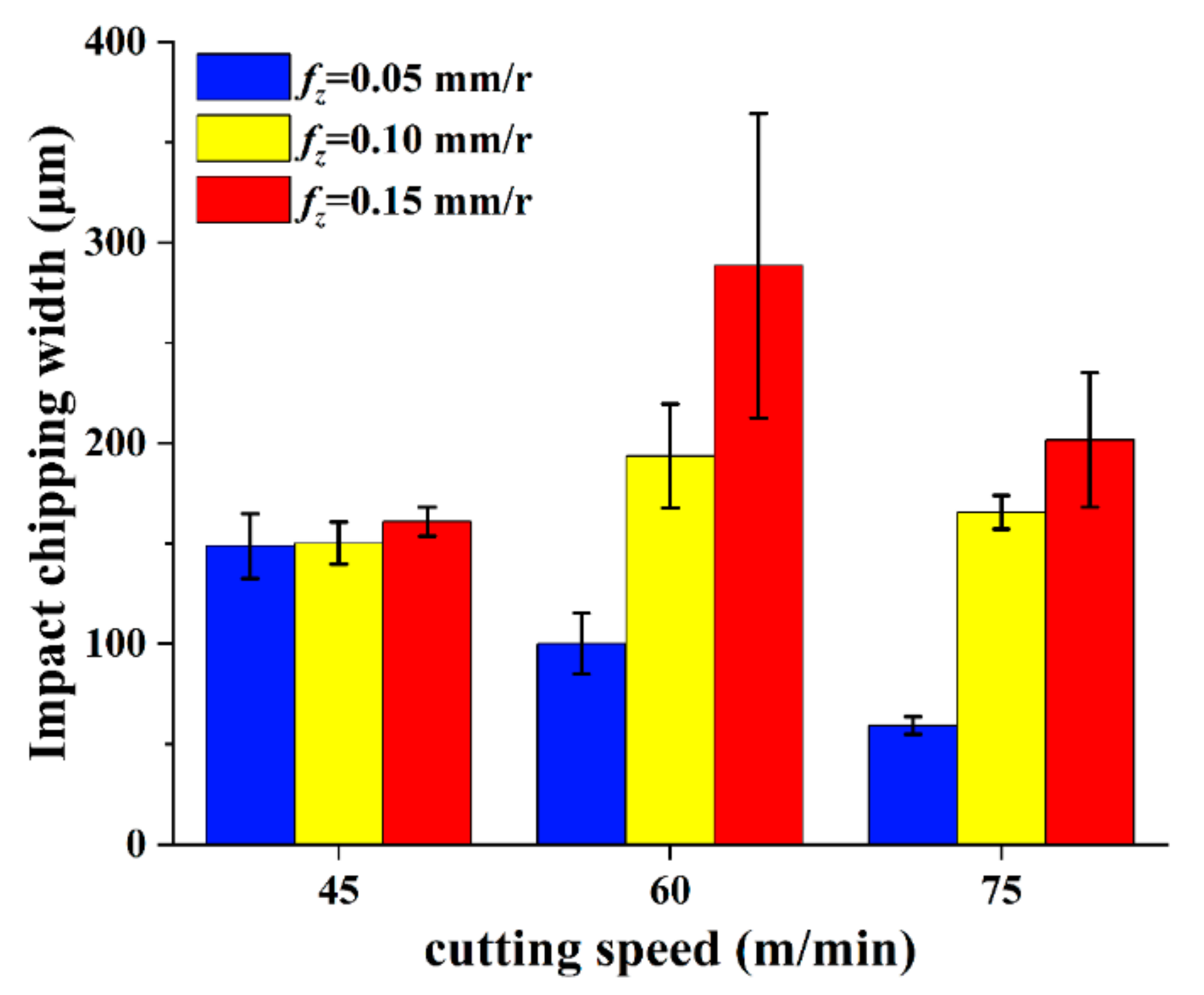
The tool edge chipping at various cutting parameters is shown in Figure 9 and Figure 10. The width of the tool edge chipping on flank face is used to evaluate the tool edge chipping. The average width of each chipping is measured from three equidistant positions, as shown in Figure 15. The width of tool edge chipping increases as the feed increases from 0.05 mm/r to 0.15 mm/r at every cutting speed. However, the maximum width of tool edge chipping is achieved at the cutting speed of 60 m/min and the feed rate of 0.10 mm/r. A similar phenomenon is also reported by Peng et al. [31] in their simulation and experiment results. The possible reason is the weakening of workpiece strength and hardness due to high cutting temperature as the cutting speed increases [32]. The reduction in crack propagation is faced as a result of the reduction in the strength and hardness of the workpiece.
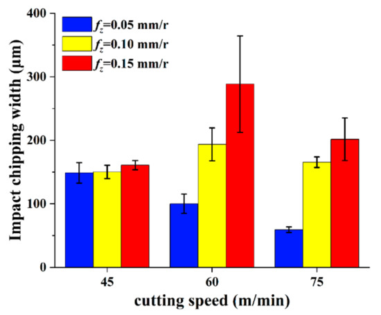
Figure 15.
Tool chipping width at various cutting parameters.
3.5. Statistical Analysis
An analysis of variance (ANOVA) analysis for the effect of cutting parameters on the output parameters is conducted. The input parameters are feed rate and cutting speed, while the output parameters are the cutting force, tool life, and tool edge chipping. The analysis employs a 90% confidence level, and the results are presented in Table 4. The relative contribution of each factor is shown in the last column of Table 4.
Table 4.
Analysis of variance for experimental results.
The analysis results show that the feed rate affects cutting force, tool life, and tool edge chipping by 61.4%, 78.0%, and 59.5%, respectively. The relative contributions of cutting speed on the effect of cutting force, tool life, and tool edge chipping are 19.2%, 17.6%, and 13.5%, respectively. It can be identified that the feed rate is the more important factor affecting output parameters under experimental conditions. The p value also shows the same result at a 90% confidence level. In addition, the analysis results indicate that the cutting speed for cutting force is statistically significant because the p value is lower than 0.10 in Table 4. Similar results could be obtained by comparison with experimental research data [33] of face milling Inconel 718 with ANOVA analysis. The p value of feed rate to tool life was 0.0412, while it was 0.1431 for cutting speed. This indicates that the effect of feed rate on tool life is more significant than that of cutting speed.
4. Conclusions
In this paper, the wear mode and associated wear mechanism of TiAlN-coated cemented carbide tools have been studied during their application in the face milling of Inconel 718. The main conclusions drawn are as follows:
- Cutting force and tool wear show a strong linear relationship. The values of the correlation coefficient R between cutting force and tool wear are all above 0.9 under different cutting parameters. The relationship between cutting force and tool wear propagation can be used for milling process planning and for the development of effective tool condition monitoring strategies.
- Mechanical and thermal shocks are the main reasons for tool edge chipping. The dislocations and micro-cracks extend to the tool surface, forming tool edge chipping. The tool edge chipping peels off due to the adhesion and friction of the workpiece material, which damages the tool surface.
- Tool flank wear multi-patterns present different behavior along the cutting edge direction. The adhesion and tool edge chipping on the flank face aggravate the tool wear. Adhesive wear, abrasive wear, diffusion wear, and tool edge chipping occur simultaneously as main wear patterns.
- Cutting parameters have a significant influence on tool wear patterns and tool life. The feed rate has a significant effect on the cutting force, tool life, and tool edge chipping at the 90% confidence level. The cutting speed only has a significant effect on the cutting force at the 90% confidence level.
An optimization model could be established in future research to optimize the machining parameters according to the comprehensive influence of cutting parameters on tool life, chipping, and cutting forces. This work provides an experimental basis for process parameter optimization to alleviate cutting tool wear in milling Inconel 718.
Author Contributions
Investigation, conceptualization, and writing—original draft, D.L.; resources, data curation, supervision, project administration, funding acquisition, Z.L.; writing—review and editing, validation, B.W. All authors have read and agreed to the published version of the manuscript.
Funding
This research was funded by the National Key Research and Development Program of China (2019YFB2005401) and the Shandong Provincial Key Research and Development Program (Major Scientific and Technological Innovation Project-2020CXGC010204), This work was also supported by grants from National Natural Science Foundation of China (No. 91860207), and Taishan Scholar Foundation.
Institutional Review Board Statement
Not applicable.
Informed Consent Statement
Not applicable.
Data Availability Statement
Not applicable.
Conflicts of Interest
The authors declare no conflict of interest. The funders had no role in the design of the study; in the collection, analyses, or interpretation of data; in the writing of the manuscript; or in the decision to publish the results.
References
- Thakur, A.; Gangopadhyay, S. State-of-the-Art in Surface Integrity in Machining of Nickel-Based Super Alloys. Int. J. Mach. Tools Manuf. 2016, 100, 25–54. [Google Scholar] [CrossRef]
- Rahman, M.; Seah, W.K.H.; Teo, T.T. The Machinability of Inconel 718. J. Mater. Process. Technol. 1997, 63, 199–204. [Google Scholar] [CrossRef]
- Ezugwu, E.O.; Bonney, J.; Yamane, Y. An Overview of the Machinability of Aeroengine Alloys. J. Mater. Process. Technol. 2003, 134, 233–253. [Google Scholar] [CrossRef]
- Anand Krishnan, N.; Mathew, J. Studies on Wear Behavior of AlTiN-Coated WC Tool and Machined Surface Quality in Micro Endmilling of Inconel 718. Int. J. Adv. Manuf. Technol. 2020, 110, 291–307. [Google Scholar] [CrossRef]
- Pawade, R.S.; Joshi, S.S. Mechanism of Chip Formation in High-Speed Turning of Inconel 718. Mach. Sci. Technol. 2011, 15, 132–152. [Google Scholar] [CrossRef]
- Liu, C.; Wang, G.F.; Li, Z.M. Incremental Learning for Online Tool Condition Monitoring Using Ellipsoid ARTMAP Network Model. Appl. Soft Comput. 2015, 35, 186–198. [Google Scholar] [CrossRef]
- Bhatt, A.; Attia, H.; Vargas, R.; Thomson, V. Wear Mechanisms of WC Coated and Uncoated Tools in Finish Turning of Inconel 718. Tribol. Int. 2010, 43, 1113–1121. [Google Scholar] [CrossRef]
- Li, Y.; Zou, B.; Shi, Z.; Huang, C.; Li, L.; Liu, H.; Zhu, H.; Yao, P.; Liu, J. Wear Patterns and Mechanisms of Sialon Ceramic End-Milling Tool during High Speed Machining of Nickel-Based Superalloy. Ceram. Int. 2021, 47, 5690–5698. [Google Scholar] [CrossRef]
- Duplak, J.; Duplakova, D.; Hatala, M.; Radchenko, S.; Sukic, E. Surveying the Topography and Examining the Quality of the Machined Surface of Selected Hardened Steels in the Milling Process. J. Eng. Res. 2021, 9, 285–301. [Google Scholar] [CrossRef]
- Thakur, D.G.; Ramamoorthy, B.; Vijayaraghavan, L. Effect of Cutting Parameters on the Degree of Work Hardening and Tool Life during High-Speed Machining of Inconel 718. Int. J. Adv. Manuf. Technol. 2012, 59, 483–489. [Google Scholar] [CrossRef]
- Imran, M.; Mativenga, P.T.; Gholinia, A.; Withers, P.J. Comparison of Tool Wear Mechanisms and Surface Integrity for Dry and Wet Micro-Drilling of Nickel-Base Superalloys. Int. J. Mach. Tools Manuf. 2014, 76, 49–60. [Google Scholar] [CrossRef]
- Hao, Z.; Gao, D.; Fan, Y.; Han, R. New Observations on Tool Wear Mechanism in Dry Machining Inconel718. Int. J. Mach. Tools Manuf. 2011, 51, 973–979. [Google Scholar] [CrossRef]
- Tamil Alagan, N.; Hoier, P.; Zeman, P.; Klement, U.; Beno, T.; Wretland, A. Effects of High-Pressure Cooling in the Flank and Rake Faces of WC Tool on the Tool Wear Mechanism and Process Conditions in Turning of Alloy 718. Wear 2019, 434–435, 102922. [Google Scholar] [CrossRef]
- Pekelharing, A.J. Cutting Tool Damage in Interrupted Cutting. Wear 1980, 62, 37–48. [Google Scholar] [CrossRef]
- De Oliveira, A.J.; Diniz, A.E.; Ursolino, D.J. Hard Turning in Continuous and Interrupted Cut with PCBN and Whisker-Reinforced Cutting Tools. J. Mater. Process. Technol. 2009, 209, 5262–5270. [Google Scholar] [CrossRef]
- Ma, Z.; Xu, X.; Huang, X.; Ming, W.; An, Q.; Chen, M. Cutting Performance and Tool Wear of SiAlON and TiC-Whisker-Reinforced Si3N4 Ceramic Tools in Side Milling Inconel 718. Ceram. Int. 2022, 48, 3096–3108. [Google Scholar] [CrossRef]
- Yu, W.; Ming, W.; An, Q.; Chen, M. Cutting Performance and Wear Mechanism of Honeycomb Ceramic Tools in Interrupted Cutting of Nickel-Based Superalloys. Ceram. Int. 2021, 47, 18075–18083. [Google Scholar] [CrossRef]
- Banda, T.; Ho, K.Y.; Akhavan Farid, A.; Lim, C.S. Characterization of Tool Wear Mechanisms and Failure Modes of TiAlN-NbN Coated Carbide Inserts in Face Milling of Inconel 718. J. Mater. Eng. Perform. 2022, 31, 2309–2320. [Google Scholar] [CrossRef]
- Gassner, M.; Schalk, N.; Tkadletz, M.; Pohler, M.; Czettl, C.; Mitterer, C. Influence of Cutting Speed and Workpiece Material on the Wear Mechanisms of CVD TiCN/Α-Al2O3 Coated Cutting Inserts during Turning. Wear 2018, 398–399, 90–98. [Google Scholar] [CrossRef]
- Zheng, G.; Xu, R.; Cheng, X.; Zhao, G.; Li, L.; Zhao, J. Effect of Cutting Parameters on Wear Behavior of Coated Tool and Surface Roughness in High-Speed Turning of 300M. Measurement 2018, 125, 99–108. [Google Scholar] [CrossRef]
- Li, A.; Zhao, J.; Hou, G. Effect of Cutting Speed on Chip Formation and Wear Mechanisms of Coated Carbide Tools When Ultra-High-Speed Face Milling Titanium Alloy Ti-6Al-4V. Adv. Mech. Eng. 2017, 9, 1–13. [Google Scholar] [CrossRef]
- Jiang, E.; Huang, L.; Jiang, F. Research on the Tool Wear Mechanism of the Wave-Edge End Mill Based on the Tool-Chip Contact Analysis. Int. J. Adv. Manuf. Technol. 2020, 108, 801–808. [Google Scholar] [CrossRef]
- Halim, N.H.A.; Haron, C.H.C.; Ghani, J.A.; Azhar, M.F. Tool Wear and Chip Morphology in High-Speed Milling of Hardened Inconel 718 under Dry and Cryogenic CO 2 Conditions. Wear 2019, 426–427, 1683–1690. [Google Scholar] [CrossRef]
- Li, K.; Zhu, K.; Mei, T. A Generic Instantaneous Undeformed Chip Thickness Model for the Cutting Force Modeling in Micromilling. Int. J. Mach. Tools Manuf. 2016, 105, 23–31. [Google Scholar] [CrossRef]
- Thakur, D.G.; Ramamoorthy, B.; Vijayaraghavan, L. Study on the Machinability Characteristics of Superalloy Inconel 718 during High Speed Turning. Mater. Des. 2009, 30, 1718–1725. [Google Scholar] [CrossRef]
- Li, K.M.; Liang, S.Y. Modeling of Cutting Forces in near Dry Machining under Tool Wear Effect. Int. J. Mach. Tools Manuf. 2007, 47, 1292–1301. [Google Scholar] [CrossRef]
- Zhang, Q.; Yao, J.; Mazumder, J. Laser Direct Metal Deposition Technology and Microstructure and Composition Segregation of Inconel 718 Superalloy. J. Iron Steel Res. Int. 2011, 18, 73–78. [Google Scholar] [CrossRef]
- Xue, C.; Chen, W. Adhering Layer Formation and Its Effect on the Wear of Coated Carbide Tools during Turning of a Nickel-Based Alloy. Wear 2011, 270, 895–902. [Google Scholar] [CrossRef]
- Khochtali, H.; Ayed, Y.; Zemzemi, F.; Bensalem, W. Tool Wear Characteristics in Rough Turning of Inconel 718 with Coated Carbide Tool under Conventional and High-Pressure Coolant Supplies. Int. J. Adv. Manuf. Technol. 2021, 114, 2371–2386. [Google Scholar] [CrossRef]
- Chen, Y.C.; Liao, Y.S. Study on Wear Mechanisms in Drilling of Inconel 718 Superalloy. J. Mater. Process. Technol. 2003, 140, 269–273. [Google Scholar] [CrossRef]
- Peng, R.; Tong, J.; Tang, X.; Chen, R.; Jiang, S. Crack Propagation and Wear Estimation of Ceramic Tool in Cutting Inconel 718 Based on Discrete Element Method. Tribol. Int. 2020, 142, 105998. [Google Scholar] [CrossRef]
- Jun, Z.; Jianxin, D.; Jianhua, Z.; Xing, A. Failure Mechanisms of a Whisker-Reinforced Ceramic Tool When Machining Nickel-Based Alloys. Wear 1997, 208, 220–225. [Google Scholar] [CrossRef]
- Jawaid, A.; Koksal, S.; Sharif, S. Cutting Performance and Wear Characteristics of PVD Coated and Uncoated Carbide Tools in Face Milling Inconel 718 Aerospace Alloy. J. Mater. Process. Technol. 2001, 116, 2–9. [Google Scholar] [CrossRef] [Green Version]


Publisher’s Note: MDPI stays neutral with regard to jurisdictional claims in published maps and institutional affiliations. |
© 2022 by the authors. Licensee MDPI, Basel, Switzerland. This article is an open access article distributed under the terms and conditions of the Creative Commons Attribution (CC BY) license (https://creativecommons.org/licenses/by/4.0/).