Article

Utilization of Metallurgical Slags in Cu-free Friction Material Formulations

by
Vlastimil Matějka
1,*,
Priyadarshini Jayashree
2,
Mara Leonardi
3,
Jozef Vlček
1,
Tomáš Sabovčík
4 and
Giovanni Straffelini
2
1
Faculty of Materials Science and Technology, VSB—Technical University of Ostrava, 17. Listopadu 2172/15, 708 33 Ostrava, Czech Republic
2
Department of Industrial Engineering, University of Trento, Via Sommarive 9, 38123 Trento, Italy
3
Brembo S.p.A., GCF Research & Development, 24040 Stezzano, Italy
4
Smolo a.s., nám. Svobody 527, Lybžice, 739 61 Třinec, Czech Republic
*
Author to whom correspondence should be addressed.
Lubricants 2022, 10(9), 219; https://doi.org/10.3390/lubricants10090219
Submission received: 17 August 2022 / Revised: 5 September 2022 / Accepted: 8 September 2022 / Published: 10 September 2022

Abstract

:
The aim of our research was to indicate the suitability of metallurgical slags (two blast furnace slags and one steel furnace slag) as the components of Cu-free friction materials. The base mixture consisted of nine components including phenolic resin, graphite, tin sulphide, steel and aramid fibers, iron powder, a mixture of barite with calcite, and vermiculite. To this base mixture, the slags with a particle size below 0.1 mm were added individually in the amount of 20 wt.%. A base friction mixture with alumina in the amount of 20 wt.% represented the reference. Samples for the friction-wear tests were produced in the form of pins by hot press molding. The prepared pins were tested using a pin-on-disc tester in a drag mode at the pressure of 1 MPa and a constant sliding speed of 1.51 m/s for 90 min. The samples with slags exhibited slightly lower values of steady-state friction coefficient compared to the reference composite with alumina, and at the same time produced lower wear particle emissions. The particle concentration was reduced for the samples with slowly cooled blast furnace and steel furnace slag. The results obtained indicated steel furnace slag as a promising component of Cu-free friction composites.

1. Introduction

Undoubtedly, the circular economy is one of the most important strategies toward sustainability connected to the saving of natural resources as well as toward the zero-waste manufacturing approach. With sustainability in mind, it is pivotal for current studies to focus on replacing primary raw materials with secondary sources. The nature and characteristics of industrial wastes depend on the utilized raw materials and the processing method. Most of the generated waste is disposed of in landfills, which could lead to soil pollution and an overall environmental imbalance [1]. Due to its possible negative environmental effects and the continued unavailability of sites for its disposal, the option of landfill utilization is steadily decreasing. Furthermore, the waste management legislation in the European Union stresses the decrease and reusing of generated waste or using only appropriate methods of disposal that may not affect the environment and humans [2,3].
The metallurgy industry is responsible for the production of a large portion of this industrial waste. The main kinds of these materials are metallurgical slags, sludge, and dust. Depending on the character of the waste, different methodologies of utilization are adopted. Different kinds of slags are produced from metallurgical processes or simply as a residue from the incineration process, and can be classified as ferrous, non-ferrous, and incineration slags. Slags are rich in important metals and have already been used in various applications; their possible utilization was comprehensively summarized in a book chapter published by Piatak [4]. Ferrous slags are produced mainly in blast and steel slag furnaces and are already used in building and road construction, but also, for example, during fertilizer production [5]. The blast furnace slag is predominantly composed of aluminosilicates and calcium silicates [6]. Moreover, steel slags contain a significant portion of Fe-based phases, predominantly oxides, followed by various phases based on CaO, MgO, and MnO, among other constituents [7]. The slags are thermally stable and require minimal pretreatment to be used in specific applications, making them valuable sources for substituting base raw materials, especially in the building industry [8,9].
Friction materials used for car brake linings are required to meet a wide range of requirements such as a stable and permissible friction coefficient, low system wear, thermal stability, desirable tribological properties in a varying range of working conditions, produce low noise and vibration, and they have to also be environmentally friendly [10,11]. The request for environmental friendliness of friction composites connected to wear particles released during the friction process has led several authors to comprehensively summarize this issue [12,13]. The production of wear particles during the friction process of composites designed for brake pads is affected by the wear mechanism. The detailed characterization of the wear mechanism in the case of friction composites designed for brake linings is difficult in comparison to the situation when the samples under investigation are of a small number of components and are usually ascribed to the combination of oxidative, adhesive, and abrasive wear mechanisms as reported in the paper published by Kukutschova et al. [14]. To reveal the processes occurring on the friction surface, which reflects the wear mechanism, the utilization of the advanced characterization techniques including scanning and transmission electron microscopy and methods of chemical and phase analysis is necessary, as evident, for example, from papers published by Österle et al. [15], Filip et al. [16], and recently of Günen et al. [17].
The friction materials for automotive braking applications can be classified into low-metallic, semi-metallic, and non-asbestos organic (NAO) types. Essentially, friction materials are made up of four categories of constituents: binders, reinforcements, fillers, and friction modifiers [18]. Binders help to hold all the components of friction material together [19], whereas the phenolic resin-based binder is the most commonly used. Reinforcements such as Cu and steel fibers provide strength and behave as primary contact plateaus, which helps in the formation of compacted and extended secondary contact plateaus, as proved, for example, by Lee et al. [20]. The utilization of Cu fibers is extremely restricted due to their adverse effects on human health and the environment [21]. Friction modifiers can be divided into lubricants and abrasives. Lubricants such as graphite, tin sulfides, molybdenum disulfide, and their relevant combinations effectively reduce wear and smooth and stabilize friction traces in a wear system [22]. Cho et al. [23] have explained that the appropriate addition of lubricants results in reduced vibration and noise produced by the stick-slip phenomenon at the mating interface. Alternatively, abrasives such as alumina, silicon carbide, magnesia, and zirconia are known to increase and stabilize the friction coefficient and remove the pyrolyzed film formed on the mating counterface, effectively eliminating negative wear [24]. It is widely known that the predominant constituent of the secondary contact plateaus is Fe oxides, which promote desirable friction and wear characteristics. Space fillers are inexpensive and abundant materials, and their role is to occupy a substantial volume of friction composites. Several research studies showed that the selection of space fillers affects the final behavior of friction composites. Park et al. [25] studied the effect of barite, calcite, and calcium hydroxide as the space fillers on the production of the wear particles and the authors observed that the utilization of barite led to the production of a higher amount of wear particles due to the increased abrasion of the brake disc.
The utilization of waste materials from different industrial processes in the formulation of friction composites represents the prospective approach towards their valorization. Recently, Wahlström et al. [26] and Matějka et al. [27] tested alkali activated granulated blast furnace slag (GBFS) as a component in the formulation of friction composites designed for car brake applications. Both authors confirmed that alkali activated GBFS behaves as an abrasive. Erdoğan et al. [28] studied the utilization of slags from a blast furnace, converter, and the slag from ferrochromium production as the fillers in epoxy composites. The authors found that epoxy composites reinforced with slags show comparable or even better tribological performance compared to epoxy composites filled with alumina. Wang et al. [29] tested blast furnace slag as the filler in phenolic resin-based friction composites designed for car brake application. The added amount of slag used ranged from 13–43 wt.%; the friction-wear performance test conducted on the speed friction tester revealed the best behavior for the samples with the highest amount of slag. Sathyamoorthy et al. [30] tested the effect of red mud, fly ash, and steel slag as fillers in non-asbestos organic friction composites and indicated that composites with fly ash are the most promising for light commercial vehicles and passenger cars. Rajan et al. [31] prepared friction composites based on phenolic resin filled with slag waste in amounts ranging from 50–65 wt.%. By evaluating the friction-wear properties obtained during the tests based on the ECE R 90 protocol, the authors observed the effect of the increasing amount of slag on different parameters. The composites with higher slag content performed better with respect to the friction coefficient, fade phenomenon, and friction stability, while the composites with lower slag content showed the best friction recovery and lower wear rate.
As is evident, there are only a few scientific papers dealing with slag as a component of friction composites dedicated to brake lining applications, and the often vague description of the slags makes it difficult to understand which of the slags was used for the preparation of friction composites. This study focuses on the friction and wear behavior of Cu-free friction composites containing three types of metallurgical slags. Two types of slags were collected from a blast furnace and differed in their cooling process. The third type of slag was produced in a basic oxygen steelmaking furnace. The friction mixtures were produced ‘in-house’ with the minimum constituents to highlight the role of the slag addition and were compared to the formulation that contains alumina. The friction-wear performance tests were conducted on a pin-on-disc tribometer. To the best of our knowledge, our paper is the first report addressing the effect of metallurgical slags as components of Cu-free friction composites on the concentration of released wear particles.

2. Materials and Methods

2.1. Materials

Granulated blast furnace slag (GBFS), blast furnace slag (BFS), and steel furnace slag (SFS) were used as the admixtures of the friction composites. The images of these slags are shown in Figure 1.
In the first step, the as received BFS and SFS slags were grounded using a jaw crusher to obtain a fraction with particle size less than 1 mm, the GBFS did not undergo this step. Subsequently, the slags were ground using a vibrational mill for 5 min and sieved to obtain a final fraction of less than 0.1 mm. The chemical composition of the slags obtained using X-ray fluorescence analysis is shown in Table 1.
Studied slags were tested as the components of two different types of friction material formulations. The first composition named ‘Basic Composition’ (BC) constituted only the essential ingredients in a typical formulation of friction material. This composition was selected to observe the role of given slags on the friction-wear and emission behavior. Four different types of BC were produced, as shown in Table 2.
The constituents of the slags are similar to the abrasives used in a typical friction material composition; with respect to this fact, the first BC constituted of alumina and was considered as a reference to the other three BCs, which contained three types of given slags, added individually in the same amount (20 wt.%) as alumina (Table 2) in reference. Figure 2 shows the morphology of the constituents of BC. This high addition of alumina and slags was intentionally carried out to prove the functionality of slags in copper-free formulations.
The different formulations of friction materials were tested in the form of pins. Pins were produced through a standardized procedure. In the first step, all the constituents in Table 2, except steel wool, were continuously mixed for an hour on a TURBULA® mixer (WAB group, Germany). Additionally, steel wool was added after step 1 and the mixture was mixed for an additional 10 min. The two-step procedure was conducted to ensure that the steel wool would not clump or form agglomerates due to prolonged mixing. The well-mixed powders were then subjected to a hot-pressing procedure. The powders were tap pressed in a tool steel cylindrical mold and hot pressed on a BUEHLER® Pneumet I (Buehler, Lake Bluff, IL, USA) hot mounting press at 100 MPa, 150 °C, and at a holding time of 10 min. Lastly, the green body was subjected to post-curing treatment in a generic muffle furnace at 200 °C for 4 h. On average, the height and diameter of the pins were 8 and 10 mm, respectively. Regardless of the formulation of friction materials, the apparent density of the pins, as evaluated from the knowledge of the volume and weight of the pins, ranged between 2.4–2.6 g/cm3.
The discs of diameter 60 mm and thickness 6 mm were machined from real pearlitic grey cast iron brake discs. The microstructure and properties of the discs are shown in Figure 3 and Table 3, respectively.

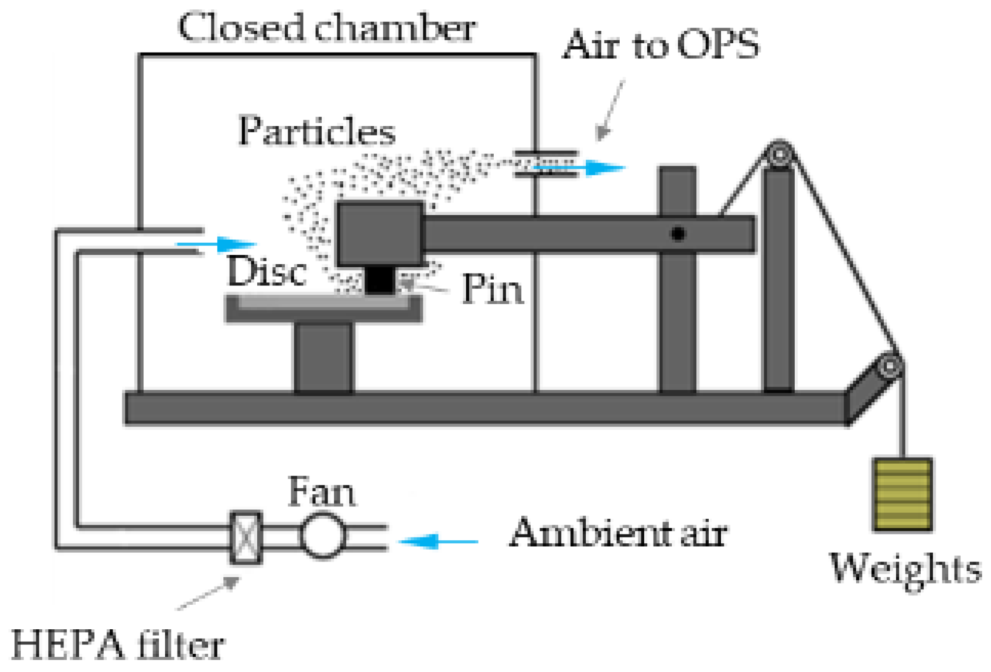
2.2. Pin-on-Disc Testing and Emission Analysis

Pins and discs were tested on a pin-on-disc (PoD) tribometer (Ducom Instruments, India). Before each trial, the discs were polished with a SiC 180 grit paper and cleaned with acetone multiple times to remove any dust, scales, grease, or impurities. A fresh disc was always used for a new test. Pin-on-disc testing was conducted at room/ambient testing conditions (22 °C and relative humidity between 40–45%). The selected parameters for the PoD test replicated mild braking conditions: contact pressure of 1 MPa (79 N) and sliding velocity of 1.51 m/s (600 rpm for a wear track diameter of 48 mm) [32,33]; the sampling rate was 1 Hz. All the trials included a 30 min run-in followed by a 90 min continuous drag test. The run-in duration ensured the proper conformance of the pin and disc surface before the own 90-min long tests. All the tests were conducted four times (always with a new friction pair) to check the repeatability of the results.
Figure 4 shows the PoD testing apparatus with the attached particle collection equipment. Air is taken from the laboratory using a fan and circulated through a High-Efficiency Particulate Air (HEPA) filter to eliminate any dirt specks and impurities, thus introducing clean air inside the PoD chamber. The air velocity was maintained at 11.5 m/s as indicated as an optimum velocity in our previous paper [34]. Before the beginning of any trial, air cleanliness was strictly inspected and maintained close to 1–2 #/cm3.
A TSI® (TSI Incorporated, Shoreview, MN, USA) Optical Particle Sizer Spectrometer OPS model 3330 was used to obtain the particle number concentration and was connected to the enclosed PoD chamber (Figure 4). The OPS model measured the particle concentration for particle sizes between 0.3–10 µm. The apparatus measured and recorded particle concentration of up to 3000 #/cm3, with a self-controlled sampling flow rate of 1 L/min; the sampling rate was 1 Hz.
The friction coefficient (CoF) and total particle concentration profiles and magnitude were directly obtained from the corresponding software attached to the PoD and OPS, respectively. The specific wear coefficient of the pins was calculated by weighing the pin before and after each test (using an analytical balance with a precision of 10−4 g), and using the following equation:
K a = V ( F   ·   d )
where V is wear volume loss (m3); F is load applied (N); d is sliding distance (m).
The disc wear track trends were procured from a stylus profilometer, obtained perpendicular to the wear track from a transverse profile.

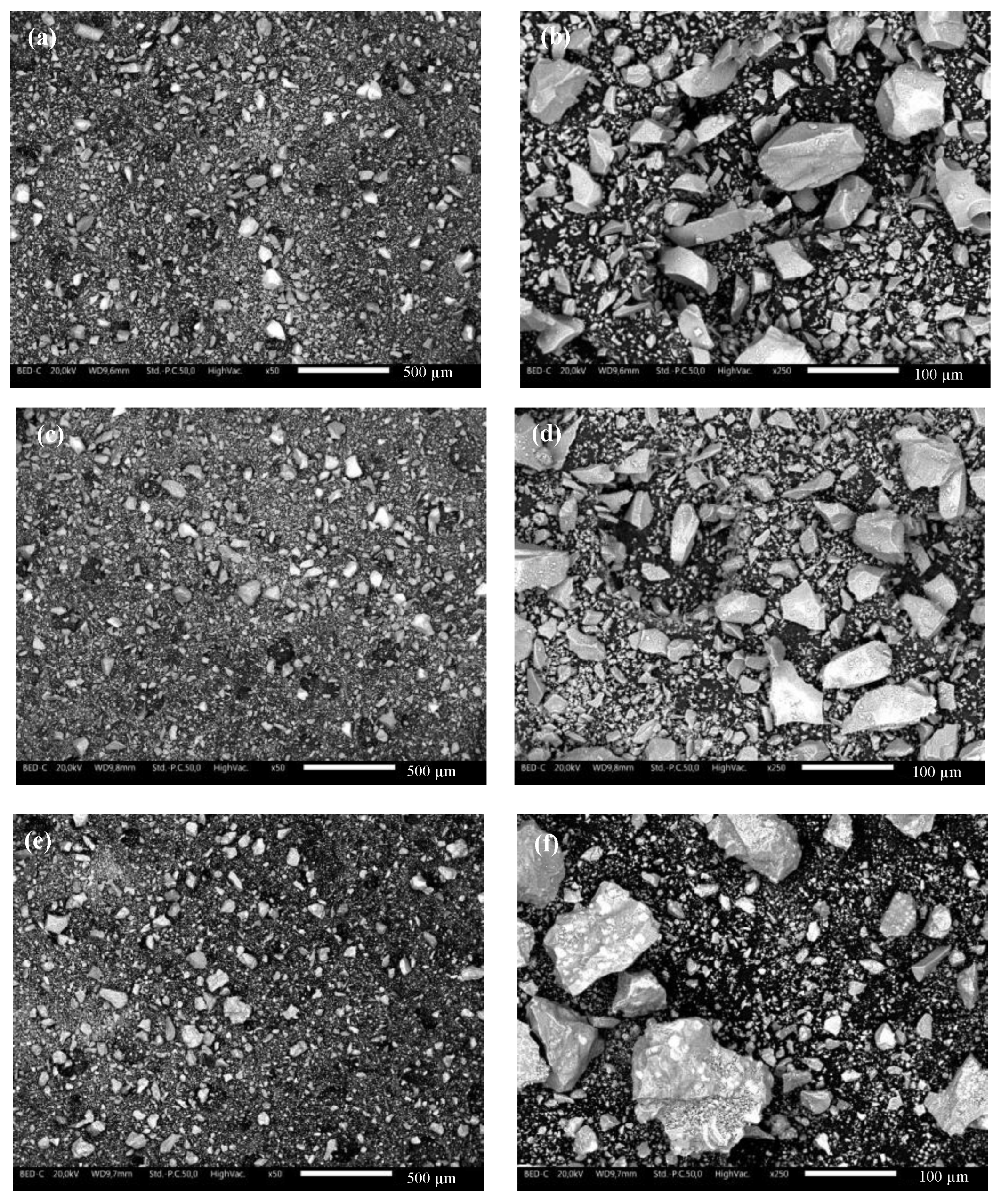
2.3. Characterization of the Slags, Materials, and Worn Surfaces

The morphology of the slag particles and the characteristics of the worn pin and disc surfaces were investigated using Scanning Electron Microscope, SEM (JEOL IT300, JEOL, Akishima, Japan), attached with Energy Dispersive X-ray Spectroscopy (EDXS; Bruker, Billerica, MA, USA) system. Furthermore, EDXS maps of the chosen elements on the worn pin surfaces were obtained to inspect the distribution of the alloying elements. To validate the maps, a total of six measurements were taken at multiple locations on different specimens. The slags were also subjected to X-ray Diffraction (XRD, Italstructures IPD3000 powder diffractometer with an Inel CPS120 detector, Erice, Italy) analysis to obtain their respective phase composition.

3. Results and Discussions

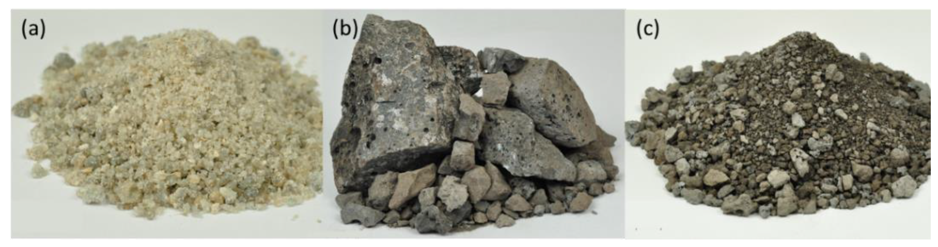
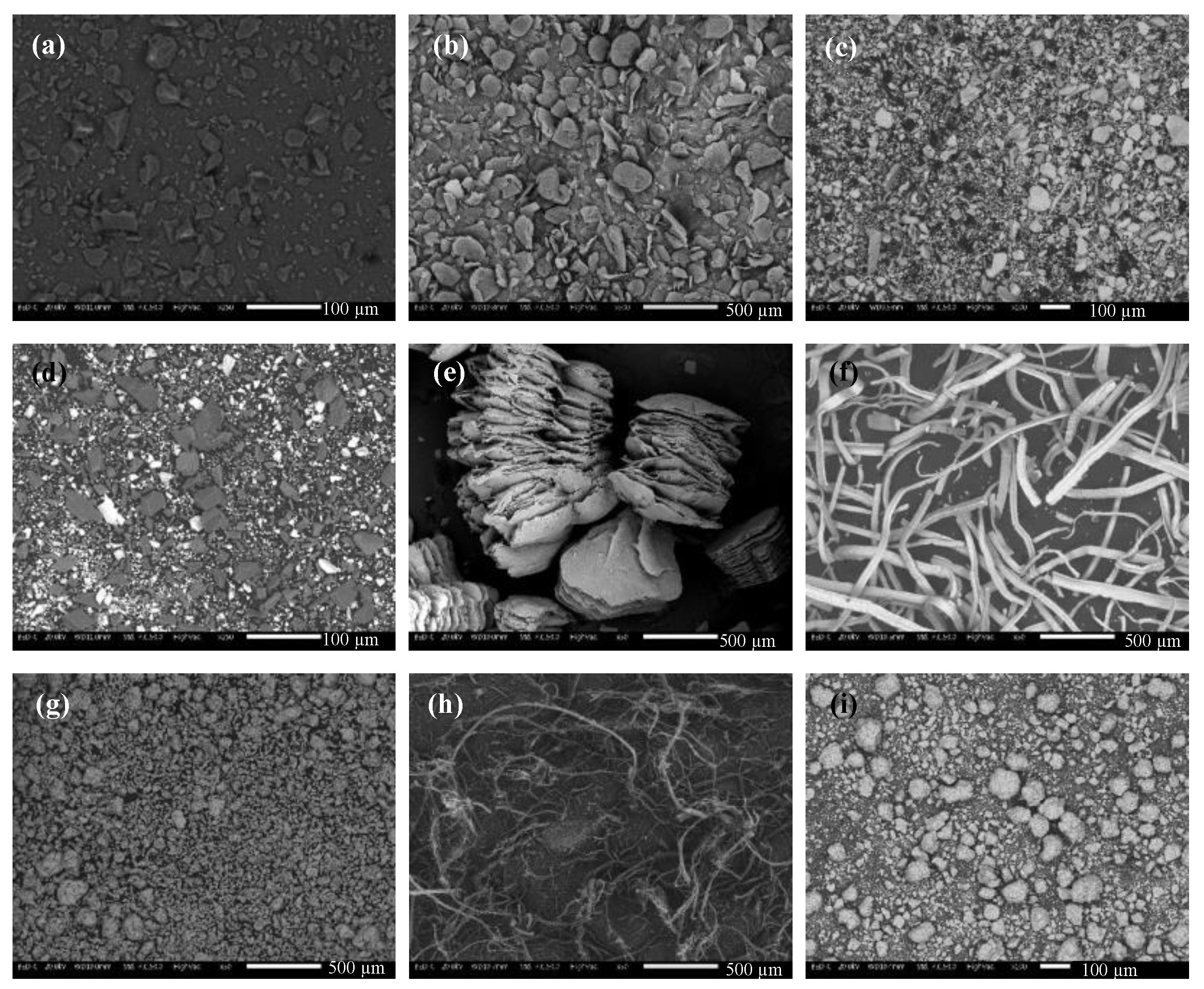
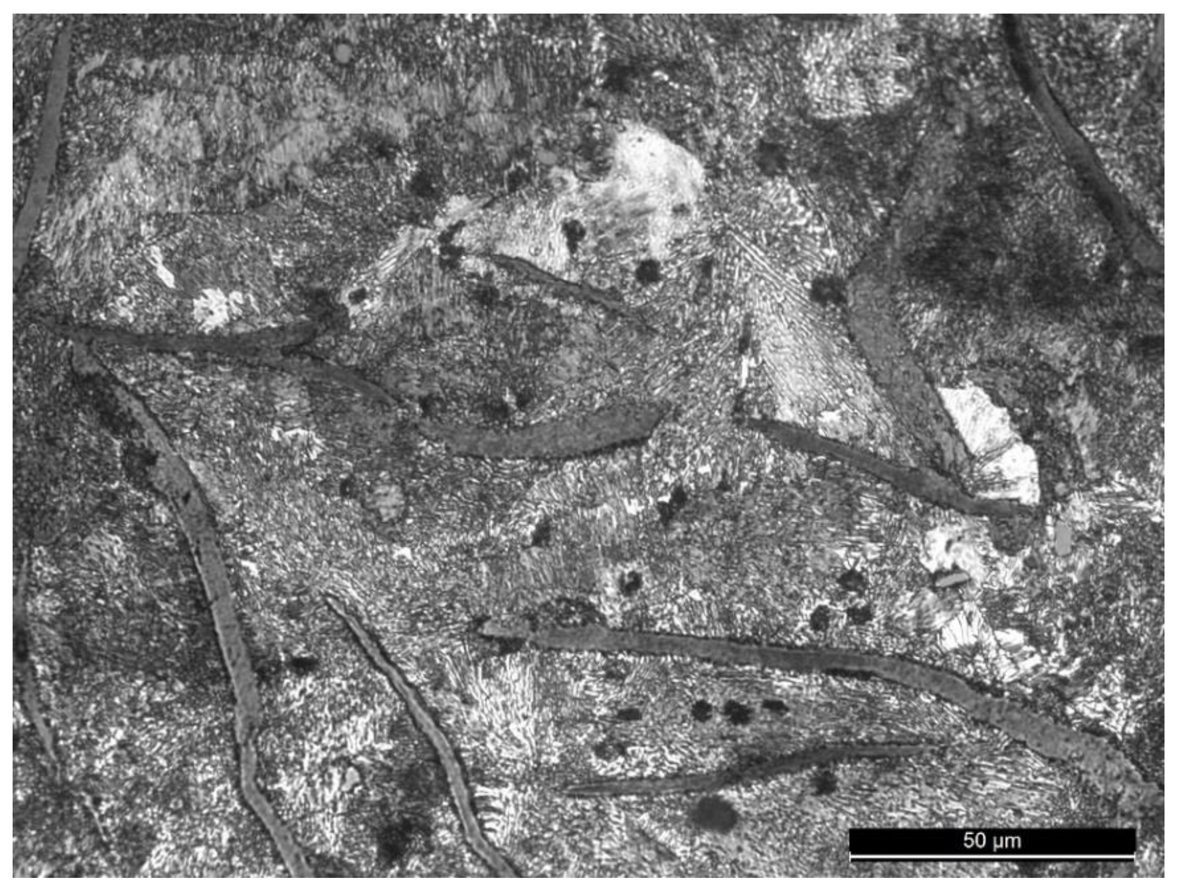
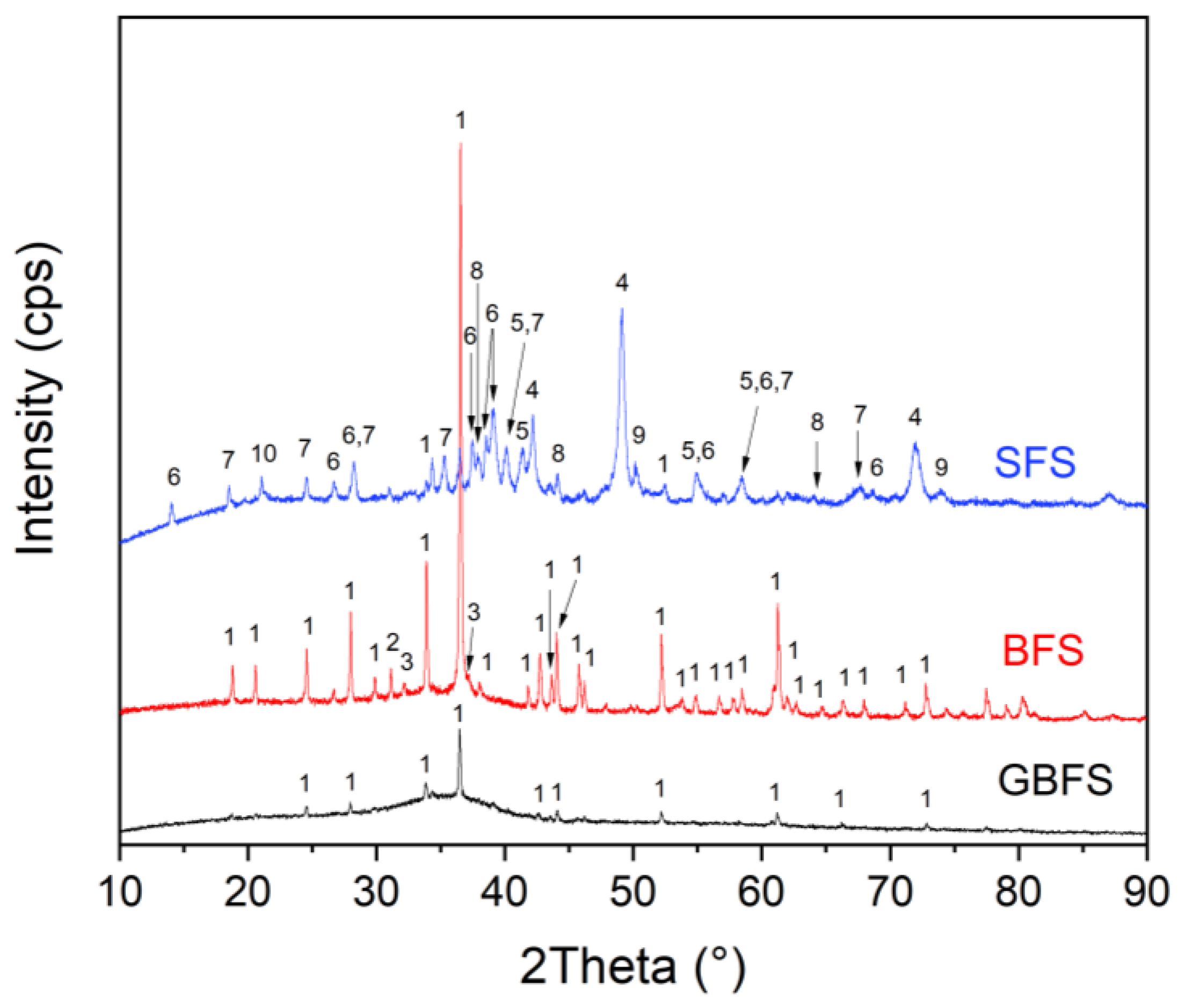
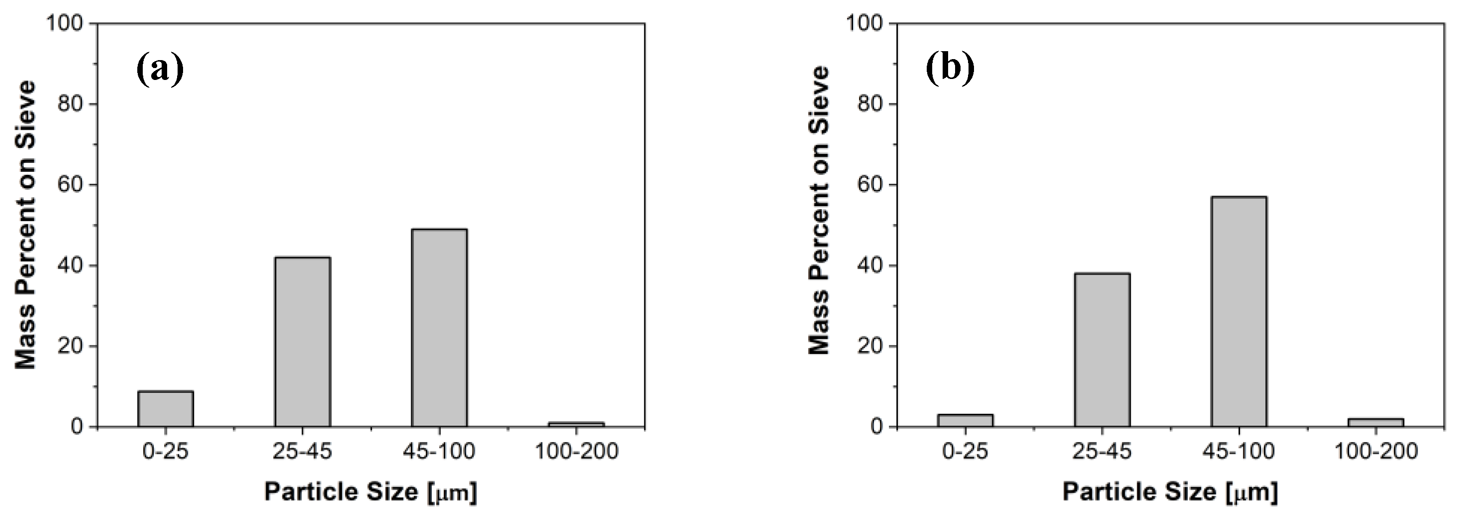
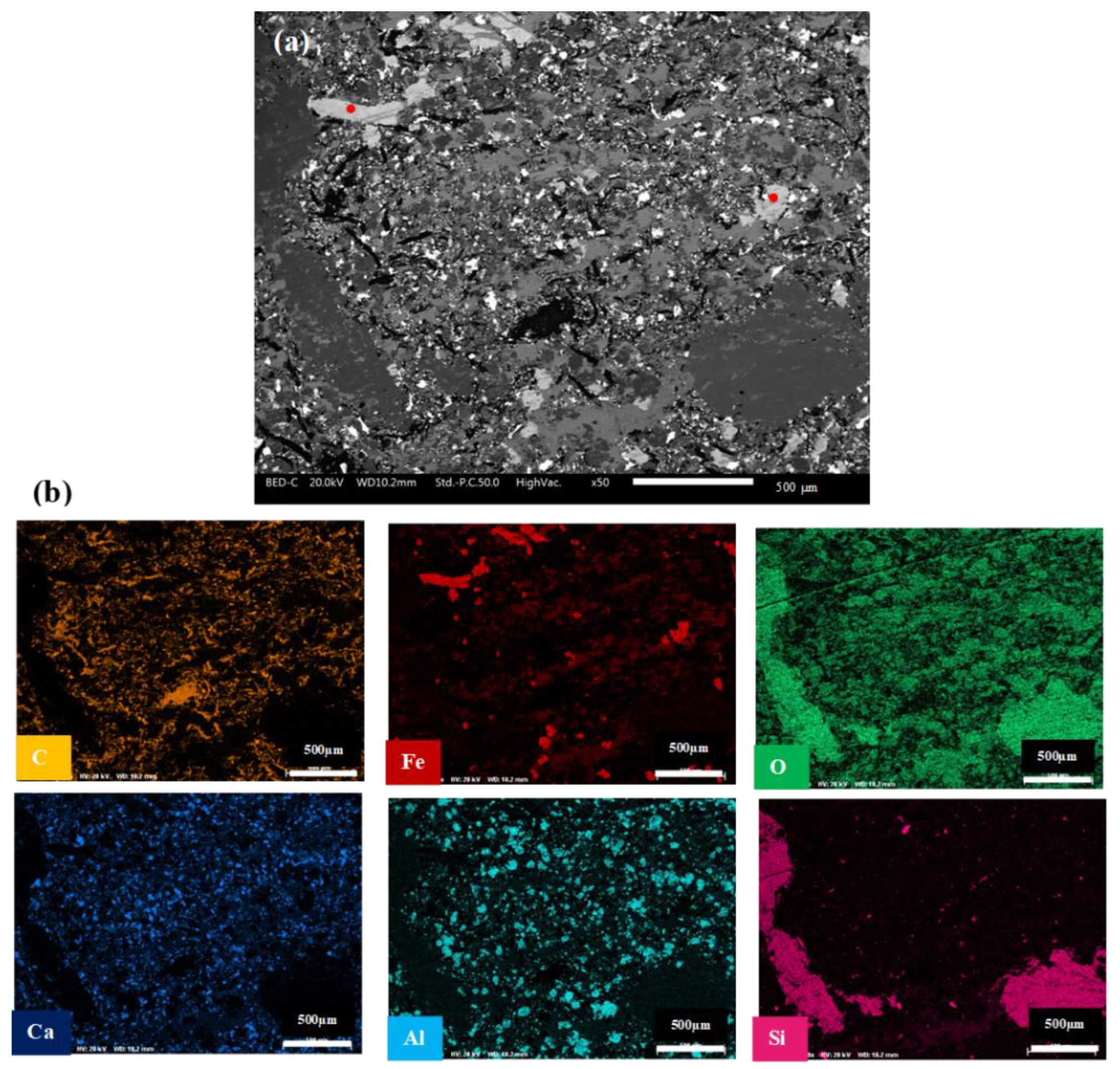
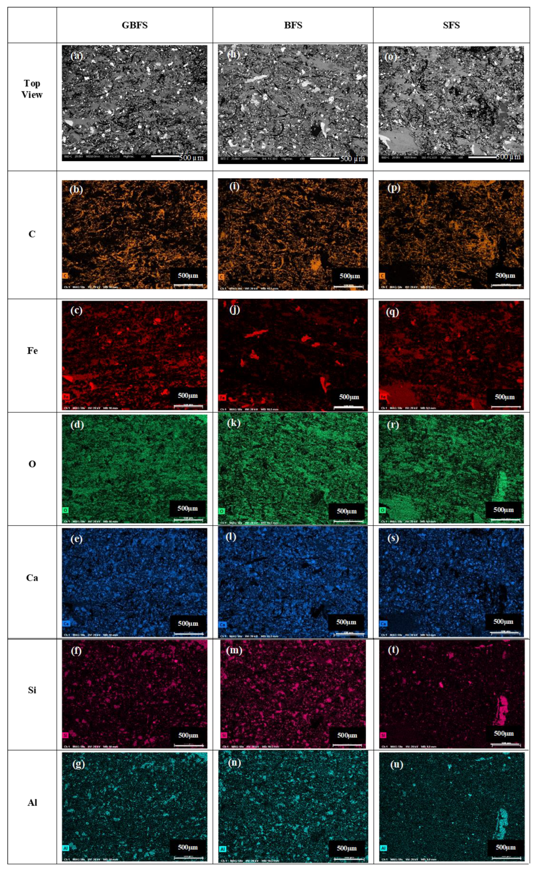
3.1. Characterization of the Metallurgical Slags

Figure 5 presents the diffraction patterns of the slags used for the modification of BC formulation, the powders obtained after the sieving of mechanically treated slags as described in Section 2.1. The presence of the diffuse peak in the region 25–40 °2Theta indicates that the GBFS contains a significant amount of amorphous phase, with the calculated amount 90.77% and the only crystalline phase indicated with XRD was akermanite (Ca2Mg(Si2O7)). The BFS and GBFS are by-products obtained during the pig iron production and show a chemical composition closely similar as evidenced in Table 1. In contrast to GBFS, BFS shows a crystalline character documented by the presence of intensive sharp peaks in its XRD pattern (Figure 5), which also belong to akermanite (Ca2Mg(Si2O7), PDF card No. 01-087-0046); other minor crystalline phases identified in BFS were quartz (SiO2, PDF card No. 01-085-0865) and pseudowollastonite (CaSiO3, PDF card No. 01-080-9543).
The higher content of amorphous phase in the case of GBFS is a result of its fast cooling during the granulation process of the molten slag, performed using a sprinkling of water over the molten slag [35]. Moreover, the comparatively higher content of well crystalline phase akermanite observed in the case of BFS is the result of slow cooling of the molten slag during which the crystallization process is promoted; for example, Kang et al. [36] showed the cooling rate 50 °C/min as the limit for the formation of the BFS with an almost totally amorphous structure. Unlike GBFS and BFS, in the case of SFS, various phases are observed, mainly wüstite (Fe0.944O, PDF card No. 01-074-1885), magnetite (Fe3O4, PDF card No. 01-085-7332) brownmillerite (Ca2(Fe2O5), PDF card No. 01-076-8615), kirschsteinite (CaFeSiO4, PDF card No. 00-011-0477), akermanite (Ca2Mg(Si2O7), PDF card No. 01-087-0046), lime (CaO, PDF card No. 01-074-1226), periclase (MgO, PDF card No. 01-075-1525), and mayenite (Ca12Al14O32, PDF card No. 01-077-5127). The high content of iron oxides in SFS is promising with respect to secondary plateaus formation during the friction process [37], which is the crucial parameter for the stability of the friction coefficient, as well as for the production of wear particle emissions.
Figure 6 shows the morphology of different slags—GBFS in Figure 6a,b, BFS in Figure 6c,d, and SFS in Figure 6e,f. The images reflect the character of the slag particles after their crushing, grinding, and sieving below 0.1 mm. At higher magnification (Figure 6b,d,e), the particles are observed to have sharp edges, which could be attributed to their crushing during the milling. Regardless of the amorphous character of GBFS, the morphology of the particles of this slag (Figure 6b) is closely similar to the character of the particles of crystalline BFS (Figure 6d). Moreover, the shape of the particles of SFS (Figure 6f) appears more irregular. Even Figure 6a,c,e shows almost identical particle size distribution, compared to Figure 6b,d,f, a higher difference in sizes of smaller and bigger particles is observed for SFS slag. The magnified image of SFS particles shown in Figure 6f demonstrates the heterogeneous character of the particle, where the white areas observed on the surface of bigger particles indicate the presence of iron reach phases encased in a grey-appearing matrix composed of calcium, aluminum, and silicon oxide-based phases. Such a complex character of SFS particles is typical of slags that originated in the BOF processes. The SFS usually contains a significantly higher content of iron, whereas this statement is strongly supported by the chemical composition of used slags presented in Table 1. X-ray diffraction revealed the presence of four different iron reach phases—wüstite, magnetite, brownmillerite, and kirschsteinite (see Figure 5), whereas the mentioned shiny appearance particles represent iron oxides.
From Figure 6, a relatively broad particle size distribution can be noted for all slag types and to better understand the trends of the particle size distribution, a generic sieve analysis was conducted on 100 g of slag powders. Figure 7 shows the particle size distribution of all slags.
For GBFS and BFS (Figure 7a), the particle size was the same, the dominant size between 45–100 µm, closely followed by 25–45 µm. Although the slag was sieved through a sieve with mesh 100 µm after the grinding, a small portion of the particles with a size between 100–200 µm was also observed, comprising particles of irregular shape with a dimension in one direction greater than 100 µm. The SFS sieve analysis, shown in Figure 7b, was also similar to GBFS and BFS with higher content of particles of sizes between 45–100 µm, followed by the particles with dimensions between 25–45 µm. In general, the particle size of the studied slags is typical of the abrasives used in friction composites [38]. Matějka et al. [39] tested the effect of the size of SiC on the friction wear performance of the low-metallic friction composite. The authors observed that SiC particles with higher size exhibit a higher friction coefficient, but at the same time a higher wear rate, and vice versa, the SiC abrasives with smaller particle size show a lower but more stable friction coefficient and a lower wear rate. From this point of view, abrasives with a broader particle size range would be a good compromise for both friction and wear performance, and the slags tested within this research are promising.

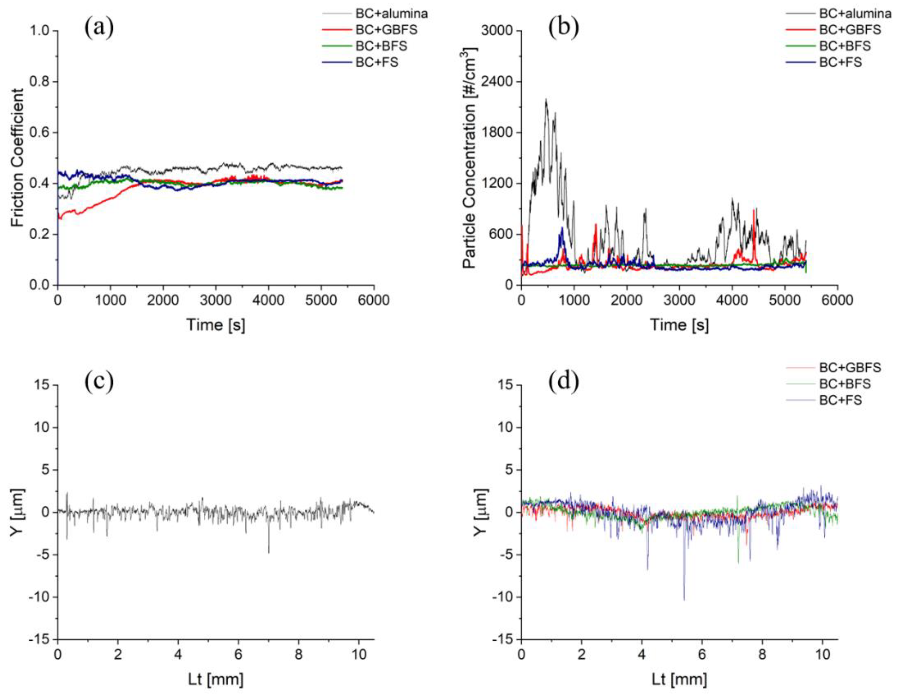
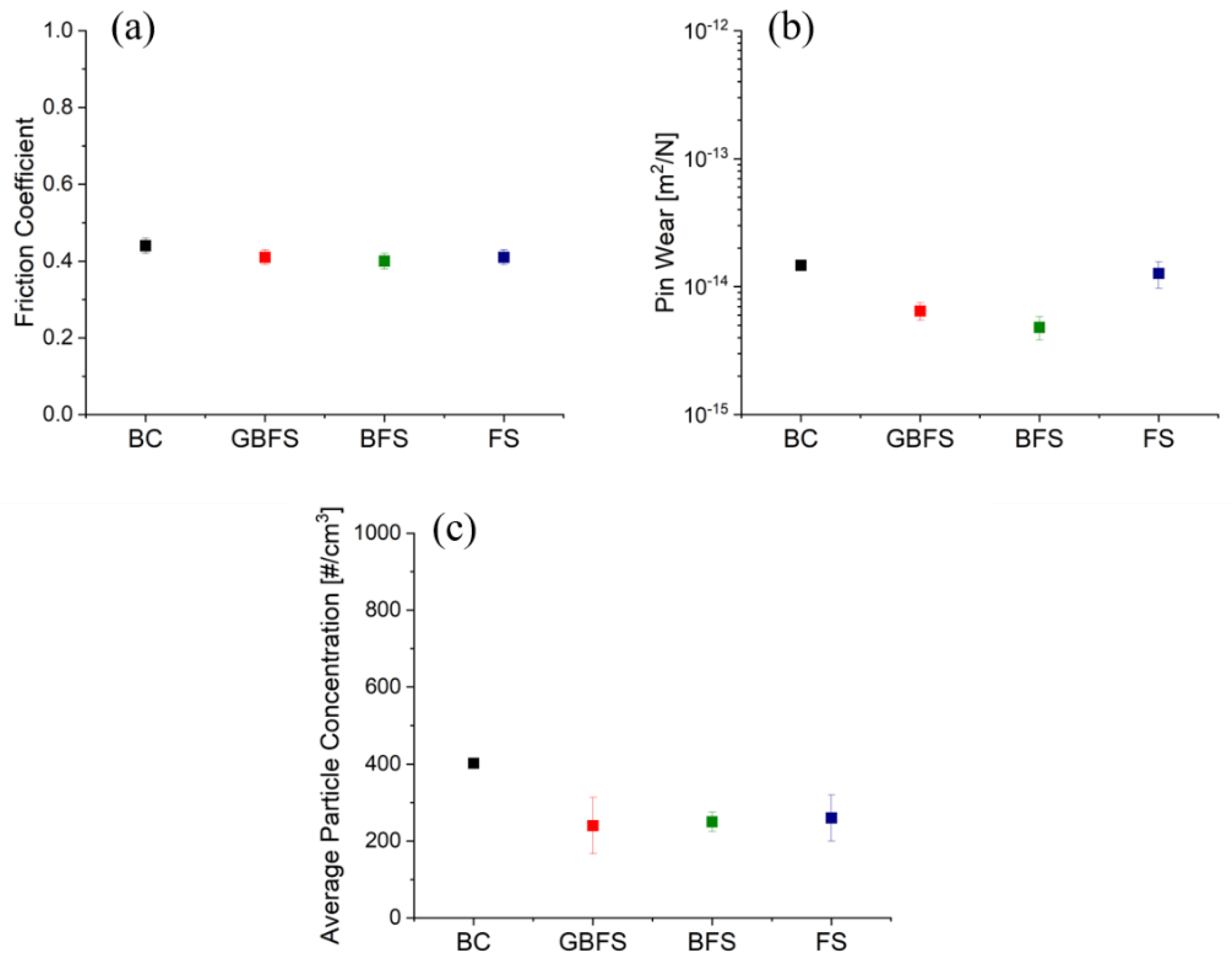
3.2. Friction, Wear, and Emissions Behavior of Friction Composites

Figure 8 shows the typical friction, emissions, and disc wear trends obtained for prepared samples. Figure 8a presents the friction trends of BC with alumina and all slags. In the case of BC with alumina, shown in black, the traces observe an initial increase in the CoF magnitude, followed by a steady state from 1500 s. In the case of BC + GBFS traces, shown in red, a steady increase in the CoF magnitude is observed until 2000 s, followed by steady-state attainment. The BC+BFS, shown in green, attains a steady state right from the beginning of the testing duration. Finally, the traces of BC+SFS pin, shown in blue, observe an initial increase in the CoF trends, followed by a reduction and steady-state attainment close to 3000 s. It is interesting to note that all three slag traces have a similar CoF magnitude, which is slightly lower than the CoF traces with alumina, most probably because of the lower hardness of slag particles in comparison to alumina. The different time necessary to achieve a steady state in the case of GBFS and BFS containing composites is most probably attributed to the different crystallinity of these slags. Akermanite, as the major constituent of BFS, can easily undergo the fragmentation process compared to the glassy phase, which is the dominant phase in GBFS, and thus can participate in the formation of secondary plateaus in the early stage of PoD tests. Different frictional behavior observed for SFS could be attributed to the complex phase character of this slag, as observed with XRD analysis. The presence of lime and mayenite in this slag increases the basicity of these friction composites, which is preferable with respect to a reduction in corrosion. Really interesting is the presence of multiphase grains in SFS (Figure 6f) which indicates that this particle would play an even more complex role during the friction process and this issue must be further studied. Figure 8b shows the typical emission trends of BC with alumina and all slags. The emission traces with alumina, shown in black, initially observe a high increase, followed by a reduction, and steady-state attainment at around 1500 s, which corresponds also with the time necessary for the stabilization of friction coefficient (compare Figure 8a,b). The initial increase in the CoF in the case of BC with alumina is also accompanied by clearly observable fluctuations in the CoF (see Figure 8a), which could be attributed to the higher abrasive character of the composite with alumina. Both the increase and fluctuations in CoF values signalize an unstable friction process, which is connected to high particle concentration at this initial period of the PoD test. The fluctuations are also typical for any emission trends, as evident in Figure 8b. Moreover, for BC samples with slags GBFS, BFS, and SFS, shown in red, green, and blue in Figure 8b, respectively, lower fluctuations and magnitude in particle concentration were observed when compared to BC with the alumina. The emission magnitudes of all three slags containing friction composites are quite similar to each other. Figure 8c shows a typical disc wear profile of BC with alumina. The downward dips of the curves on the negative Y-axis denote wear, so the Y-axis labeled as ‘Y’ shows the depth or height of given morphological features registered in a given position (Lt) on the analyzed track. Figure 8d shows the disc wear profiles of BC with GBFS, BFS, and SFS in red, green, and blue, respectively. In Figure 8d, the disc wear trends of all slags are quite similar to each other.
Figure 9 compares the steady-state CoF (Figure 9a), the steady-state average particle concentration (emissions, Figure 9b), and the magnitude of pin wear (Figure 9c) for BC with alumina and BC modified with slags. All of the points in Figure 9 represent an average value obtained from four independent PoD tests and are associated with error bars showing the variability of the average value of a given parameter. Compared to BC+alumina, the CoF is slightly reduced for the BC specimens containing slags. The error bars connected to the average value of steady-state CoF show almost the same magnitude for all of the tested composites and thus characterize closely similar variability in frictional behavior in the steady-state conditions. The lower CoF values observed for composites with GBFS and BFS slags are most probably connected to their lower hardness in comparison to the hardness of alumina particles. The higher pin wear observed for SFS is related to the larger particle size of this slag as shown in Section 3.1. and is consistent with the observation of Sethupathi and Chandradass [40], who studied the effect of the size of zirconium silicate and mullite as abrasives on the friction-wear performance of brake pads. The presence of bigger particles in the SFS slag signals that the particles are more resistant to impacts of grinding elements (note: all of the tested slags were milled under the same conditions) and indicates a higher hardness of the SFS particles. The higher hardness of the SFS particles is responsible for their higher abrasive character, which is further reflected in the higher CoF value observed for BC + SFS composites compared to other slag containing samples. For the pin wear, BCs with GBFS and BFS observed comparatively lower wear, and the pin wear of BC with SFS is similar to BC with alumina; however, the pin wear for all specimens is in the mild category (less than 2 × 10⁻¹⁴–10−15 m2/N). Disc wear is not compared in this case, as the corresponding magnitude for all samples varied in the range of 10−16 m2/N, which is significantly lower than pin wear. Figure 9c shows that the emissions are quite reduced and appeared almost at the same level for the slag containing BC, compared to BC with alumina. The sources of wear particle emissions during the friction process are both the stationary pin and the rotating cast iron disc. The complex character of the SFS particles predetermines better compatibility of the particles of this slag with the cast iron disc and thus indicates that the BC+SFS pins are less aggressive to the cast iron disc, which led to a decreased contribution of the disc wear to the production of wear particles.

3.3. Analysis of BC Worn Pin Surfaces

Figure 10 shows a typical example of the worn surface of the BC pin with the corresponding EDXS maps of selected elements to understand the distribution of alloying elements on the worn surface. The surface observes the presence of white regions recognized through red dots Figure 10a. These are the steel fibers (evidenced by the presence of Fe in maps) and are categorized as primary contact plateaus. The black region on the worn surface is graphite. Another dominant region is denoted by light grey color representing the secondary contact plateaus. From the EDXS maps in Figure 10b, the light grey mixtures are made of Fe and O, denoting Fe oxides. The secondary contact plateaus are observed to have a notable presence on the surface, forming compacted patches all around. The surface also constitutes alumina, spread evenly throughout, as seen from the Al maps in Figure 10b.
Figure 11 shows the worn surfaces of BC containing GBFS (Figure 11a–g), BFS (Figure 11h–n), and SFS (Figure 11o–u). The characteristics of the worn surface remain similar to those of the friction surface of BC with alumina (Figure 10). However, it should be noted that the extension of the secondary contact plateaus (light grey regions) is much higher, compacted, and extended when compared to the specimen of BC with alumina presented in Figure 10. Another interesting observation is the uniform spread of Ca, Si, and Al oxides on the worn surface. When the slag and BC constituents are considered, it can be inferred that these oxides are part of the slag composition. Additionally, in this case, the secondary contact plateaus are predominantly made of Fe oxides. By comparing the SEM micrographs in Figure 10a and Fiugre 11a,h,o, a higher population of the secondary contact plateaus and their coverage is indicated for the BC + BFS sample. The element maps of Si, Figure 11m, and Al, Figure 11n, also show a higher occurrence of these elements on the friction surface of the BC + BFS sample. Moreover, Figure 11j shows the lowest occurrence of Fe on the friction surface of this sample. The lower occupancy of the friction surface with iron could be attributed to the lower abrasion of the disc rotor. Both higher Ca together with higher Al content, and lower iron content on the friction surface of the BC + BFS sample also indicate the formation of a stable friction layer, which is supported by the significantly lower spread of the particle concentration values as evidenced in Figure 9b by the lowest extension of the error bar.
To better understand the constituents of the secondary plateaus in all BC specimens, point EDXS analyses were performed at six different secondary contact plateau sites in multiple BC specimens. Table 4 shows the summary of the analysis. For all cases, the secondary contact plateaus are mainly formed of Fe and O with the addition of Al, Ba, and Sn for virgin BC. Secondary contact plateaus of BC with slag specimens consist of the same elements as the BC+alumina sample, with the exception of manganese, detected in the case of slag containing specimens. A higher content of Ca and Si was observed for secondary contact plateaus of slag containing samples, whereas these elements are major constituents of slags.

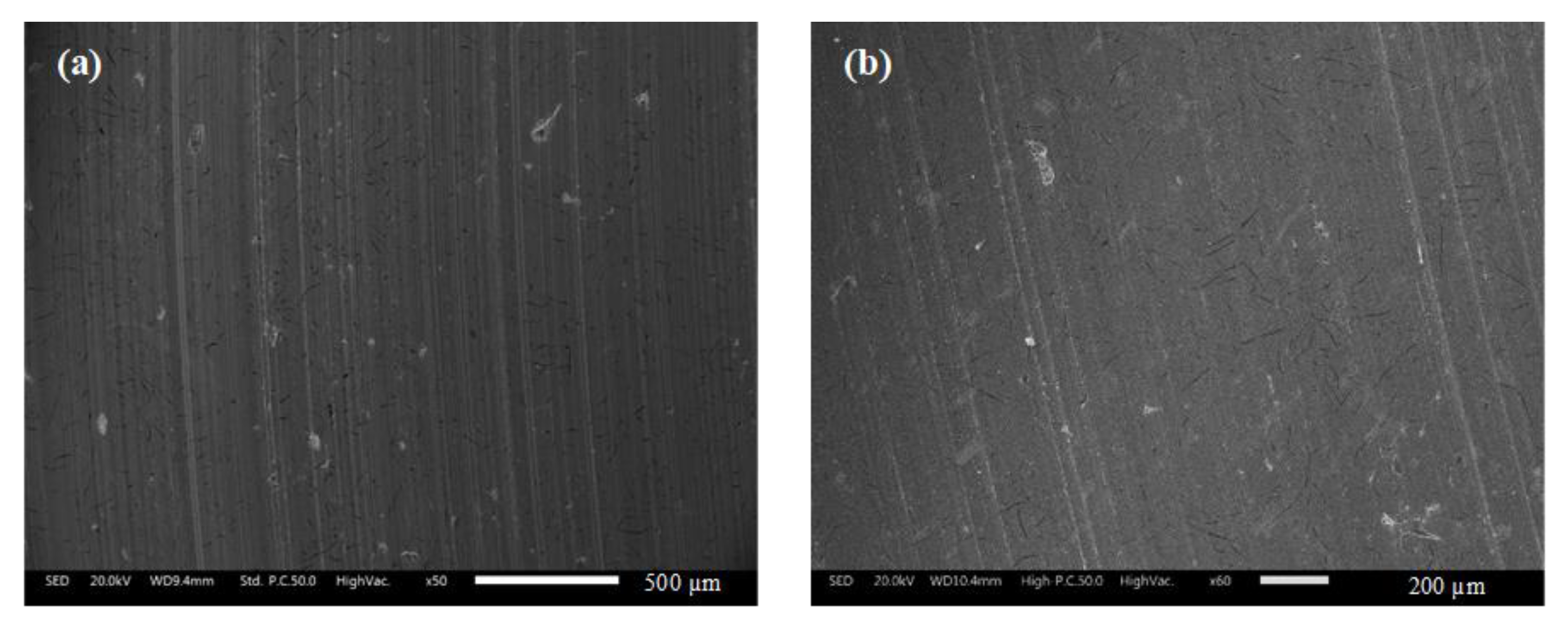
3.4. Analysis of Worn Disc Surfaces

Figure 12a,b shows the worn disc surfaces paired with BC+alumina and BC+SFS, respectively. The disc after the test of BC with alumina composite (Figure 12a) observes a few faint scratches. However, the surface of the disc after the test of BC + SFS composite shown in Figure 12b indicates a smoother character. The Mohs hardness of alumina abrasive is reported as 9 and thus alumina is considered a hard abrasive. Although the steel furnace slag exhibits a very complex phase composition, it is expected that the phases presented in the steel furnace slag have a lower hardness than alumina and are less aggressive to the cast iron disc. This statement is also supported by the lower CoF value obtained for sample BC + SFS in comparison to the reference sample BC+alumina (Figure 9).

4. Conclusions

In this paper, the effect of three different metallurgical slags on friction-wear performance and wear particle emissions during the friction test of Cu-free friction composites was studied. In-house designed base Cu-free friction mixture was modified with granulated blast furnace slag, slowly cooled blast furnace slag, and steel furnace slag. The Cu-free mixture with alumina added in the same content as the slags was used as the reference. The character of the slags influences the friction-wear performance, as well as wear particle emissions. The presence of alumina, as a typical hard abrasive, caused slightly elevated values of friction coefficient when compared to the parameter obtained for the simplified composition with slags. This fact is attributed to the higher hardness of alumina abrasive in comparison to slag particles. Moreover, taking into account the friction performance of the samples, the concentration of wear particles released during the test was significantly reduced in the case of the slag containing samples. The wear rate of the pins depended on the type of slag; the lowest wear rate of the pins was observed for granulated and slowly cooled blast furnace slag, while the pins with steel furnace slag showed a wear rate comparable to that of the reference pins with alumina. Low wear particle emission, but at the same time, a higher pin wear rate obtained in the case of the samples with steel furnace slag, implies that this friction material is less aggressive toward the cast iron disc.
In this investigation, we confirmed the usability of the selected types of metallurgical slag as mild abrasives in the formulation of Cu-free friction composites. Comparing three types of slag, steel furnace slag was indicated as the most promising. The positive indication of steel furnace slags as one of the components of friction mixtures evokes the need for further studies that are focused on the tuning of the slag content in friction composites, testing the slags in multicomponent Cu-free formulations used for real brake pad manufacturing, and testing the proposed formulations on a sub-scale and full-scale level.
From a sustainability point of view, the confirmation of the steel slags as the suitable component of Cu-free friction composites is important. The components of friction materials are quite often of natural origin, and their substitution with steel furnace slags would lead to their preservation. Further research will focus on the effect of the steel furnace slags on friction-wear performance and wear particle emissions during real brake scenarios.

Author Contributions

Investigation, P.J. and V.M.; Writing—Original Draft, P.J. and V.M.; Discussion, G.S., P.J., J.V., V.M. and T.S.; Writing—Review and Editing, V.M., P.J., G.S. and T.S.; Conceptualization, G.S. and J.V.; Data Treatment, P.J. and V.M.; Methodology, G.S. and J.V.; Software, P.J. and V.M.; Validation, M.L.; Resources, M.L., J.V. and T.S.; Supervision, G.S., J.V. and M.L.; Funding acquisition, J.V. All authors have read and agreed to the published version of the manuscript.

Funding

This work was supported by the Ministry of Education, Youth and Sports of the Czech Republic under project “Research on the management of waste, materials and other products of metallurgy and related sectors” (CZ.02.1.01/0.0/0.0/17_049/0008426).

Data Availability Statement

The data presented in this study are available on request from the author.

Acknowledgments

The authors thank Kryštof Foniok for his support during the treatment of the metallurgical slags. The authors also thank Silvie Vallová for the TG analysis.

Conflicts of Interest

The authors declare no conflict of interest.

References

  1. Nai, C.; Tang, M.; Liu, Y.; Xu, Y.; Dong, L.; Liu, J.; Huang, Q. Potentially contamination and health risk to shallow groundwater caused by closed industrial solid waste landfills: Site reclamation evaluation strategies. J. Clean. Prod. 2021, 286, 125402. [Google Scholar] [CrossRef]
  2. Šajn, R.; Ristović, I.; Čeplak, B. Mining and Metallurgical Waste as Potential Secondary Sources of Metals—A Case Study for the West Balkan Region. Minerals 2022, 12, 547. [Google Scholar] [CrossRef]
  3. Shen, H.; Forssberg, E. An overview of recovery of metals from slags. Waste Manag. 2003, 23, 933–949. [Google Scholar] [CrossRef]
  4. Piatak, N.M. Chapter 19—Environmental Characteristics and Utilization Potential of Metallurgical Slag. In Environmental Geochemistry, 2nd ed.; De Vivo, B., Belkin, H.E., Lima, A., Eds.; Elsevier: Amsterdam, The Netherlands, 2018; pp. 487–519. [Google Scholar] [CrossRef]
  5. Das, P.; Upadhyay, S.; Dubey, S.; Singh, K.K. Waste to wealth: Recovery of value-added products from steel slag. J. Environ. Chem. Eng. 2021, 9, 105640. [Google Scholar] [CrossRef]
  6. Giergiczny, Z. Fly ash and slag. Cem. Concr. Res. 2019, 124, 105826. [Google Scholar] [CrossRef]
  7. Naidu, T.S.; Sheridan, C.M.; van Dyk, L.D. Basic oxygen furnace slag: Review of current and potential uses. Miner. Eng. 2020, 149, 106234. [Google Scholar] [CrossRef]
  8. Díaz-Piloneta, M.; Terrados-Cristos, M.; Álvarez-Cabal, J.V.; Vergara-González, E. Comprehensive Analysis of Steel Slag as Aggregate for Road Construction: Experimental Testing and Environmental Impact Assessment. Materials 2021, 14, 3587. [Google Scholar] [CrossRef]
  9. Loureiro, C.D.A.; Moura, C.F.N.; Rodrigues, M.; Martinho, F.C.G.; Silva, H.M.R.D.; Oliveira, J.R.M. Steel Slag and Recycled Concrete Aggregates: Replacing Quarries to Supply Sustainable Materials for the Asphalt Paving Industry. Sustainability 2022, 14, 5022. [Google Scholar] [CrossRef]
  10. Irawan, A.P.; Fitriyana, D.F.; Tezara, C.; Siregar, J.P.; Laksmidewi, D.; Baskara, G.D.; Abdullah, M.Z.; Junid, R.; Hadi, A.E.; Hamdan, M.H.M.; et al. Overview of the Important Factors Influencing the Performance of Eco-Friendly Brake Pads. Polymers 2022, 14, 1180. [Google Scholar] [CrossRef]
  11. Leonardi, M.; Menapace, C.; Matějka, V.; Gialanella, S.; Straffelini, G. Pin-on-disc investigation on copper-free friction materials dry sliding against cast iron. Tribol. Int. 2018, 119, 73–81. [Google Scholar] [CrossRef]
  12. Grigoratos, T.; Martini, G. Brake wear particle emissions: A review. Environ. Sci. Pollut. Res. 2015, 22, 2491–2504. [Google Scholar] [CrossRef] [PubMed]
  13. Wang, Y.; Yin, H.; Yang, Z.; Su, S.; Hao, L.; Tan, J.; Wang, X.; Niu, Z.; Ge, Y. Assessing the brake particle emissions for sustainable transport: A review. Renew. Sustain. Energy Rev. 2022, 167, 112737. [Google Scholar] [CrossRef]
  14. Kukutschová, J.; Roubíček, V.; Malachová, K.; Pavlíčková, Z.; Holuša, R.; Kubačková, J.; Mička, V.; MacCrimmon, D.; Filip, P. Wear mechanism in automotive brake materials, wear debris and its potential environmental impact. Wear 2009, 267, 807–817. [Google Scholar] [CrossRef]
  15. Österle, W.; Kloß, H.; Urban, I.; Dmitriev, A.I. Towards a better understanding of brake friction materials. Wear 2007, 263, 1189–1201. [Google Scholar] [CrossRef]
  16. Filip, P.; Weiss, Z.; Rafaja, D. On friction layer formation in polymer matrix composite materials for brake applications. Wear 2002, 252, 189–198. [Google Scholar] [CrossRef]
  17. Günen, A.; Bölükbaşı, Ö.S.; Özgürlük, Y.; Özkan, D.; Odabaş, O.; Somunkıran, İ. Effect of Cr Addition on Properties and Tribological Behavior at Elevated Temperature of Boride Layers Grown on Borosintered Powder Metallurgy Alloys. Met. Mater. Int. 2022, 1–19. [Google Scholar] [CrossRef]
  18. Chan, D.; Stachowiak, G.W. Review of automotive brake friction materials. Proc. Inst. Mech. Eng. Part D J. Automob. Eng. 2004, 218, 953–966. [Google Scholar] [CrossRef]
  19. Kim, S.J.; Jang, H. Friction and wear of friction materials containing two different phenolic resins reinforced with aramid pulp. Tribol. Int. 2000, 33, 477–484. [Google Scholar] [CrossRef]
  20. Lee, J.-J.; Lee, J.-A.; Kwon, S.; Kim, J.-J. Effect of different reinforcement materials on the formation of secondary plateaus and friction properties in friction materials for automobiles. Tribol. Int. 2018, 120, 70–79. [Google Scholar] [CrossRef]
  21. Straffelini, G.; Ciudin, R.; Ciotti, A.; Gialanella, S. Present knowledge and perspectives on the role of copper in brake materials and related environmental issues: A critical assessment. Environ. Pollut. 2015, 207, 211–219. [Google Scholar] [CrossRef]
  22. Baskara Sethupathi, P.; Chandradass, J. Comparative study of different solid lubricants towards friction stability in a non-asbestos disc brake pad. Ind. Lubr. Tribol. 2021, 73, 897–903. [Google Scholar]
  23. Cho, M.H.; Ju, J.; Kim, S.J.; Jang, H. Tribological properties of solid lubricants (graphite, Sb2S3, MoS2) for automotive brake friction materials. Wear 2006, 260, 855–860. [Google Scholar] [CrossRef]
  24. Fan, Y.; Matějka, V.; Kratošová, G.; Lu, Y. Role of Al2O3 in Semi-Metallic Friction Materials and its Effects on Friction and Wear Performance. Tribol. Trans. 2008, 51, 771–778. [Google Scholar] [CrossRef]
  25. Park, J.; Gweon, J.; Seo, H.; Song, W.; Lee, D.; Choi, J.; Kim, Y.C.; Jang, H. Effect of space fillers in brake friction composites on airborne particle emission: A case study with BaSO4, Ca(OH)2, and CaCO3. Tribol. Int. 2022, 165, 107334. [Google Scholar] [CrossRef]
  26. Wahlström, J.; Lyu, Y.; Matjeka, V.; Söderberg, A. A pin-on-disc tribometer study of disc brake contact pairs with respect to wear and airborne particle emissions. Wear 2017, 384–385, 124–130. [Google Scholar] [CrossRef]
  27. Matějka, V.; Perricone, G.; Vlček, J.; Olofsson, U.; Wahlström, J. Airborne Wear Particle Emissions Produced during the Dyno Bench Tests with a Slag Containing Semi-Metallic Brake Pads. Atmosphere 2020, 11, 1220. [Google Scholar] [CrossRef]
  28. Erdoğan, A.; Gök, M.S.; Koç, V.; Günen, A. Friction and wear behavior of epoxy composite filled with industrial wastes. J. Clean. Prod. 2019, 237, 117588. [Google Scholar] [CrossRef]
  29. Wang, Z.; Hou, G.; Yang, Z.; Jiang, Q.; Zhang, F.; Xie, M.; Yao, Z. Influence of slag weight fraction on mechanical, thermal and tribological properties of polymer based friction materials. Mater. Des. 2016, 90, 76–83. [Google Scholar] [CrossRef]
  30. Sathyamoorthy, G.; Vijay, R.; Singaravelu, D.L. A comparative study on tribological characterisations of different abrasives based non-asbestos brake friction composites. Mater. Today Proc. 2022, 56, 661–668. [Google Scholar] [CrossRef]
  31. Rajan, R.; Tyagi, Y.K.; Pruncu, C.I.; Kulshreshtha, S.; Ranakoti, L.; Singh, T. Tribological performance evaluation of slag waste filled phenolic composites for automotive braking applications. Polym. Compos. 2022, in press. [Google Scholar] [CrossRef]
  32. Menapace, C.; Leonardi, M.; Matějka, V.; Gialanella, S.; Straffelini, G. Dry sliding behavior and friction layer formation in copper-free barite containing friction materials. Wear 2018, 398–399, 191–200. [Google Scholar] [CrossRef]
  33. Jayashree, P.; Matějka, V.; Foniok, K.; Straffelini, G. Comparative Studies on the Dry Sliding Behavior of a Low-Metallic Friction Material with the Addition of Graphite and Exfoliated g-C3N4. Lubricants 2022, 10, 27. [Google Scholar] [CrossRef]
  34. Jayashree, P.; Sinha, A.; Gialanella, S.; Straffelini, G. Dry Sliding Behavior and Particulate Emissions of a SiC-graphite Composite Friction Material Paired with HVOF-Coated Counterface. Atmosphere 2022, 13, 296. [Google Scholar] [CrossRef]
  35. Tripathy, S.K.; Dasu, J.; Murthy, Y.R.; Kapure, G.; Pal, A.R.; Filippov, L.O. Utilisation perspective on water quenched and air-cooled blast furnace slags. J. Clean. Prod. 2020, 262, 121354. [Google Scholar] [CrossRef]
  36. Kang, Y.; Liu, C.; Zhang, Y.; Xing, H.; Jiang, M. Crystallization behavior of amorphous slag beads prepared by gas quenching of blast furnace slag. J. Non-Cryst. Solids 2018, 500, 453–459. [Google Scholar] [CrossRef]
  37. Österle, W.; Deutsch, C.; Gradt, T.; Orts-Gil, G.; Schneider, T.; Dmitriev, A.I. Tribological screening tests for the selection of raw materials for automotive brake pad formulations. Tribol. Int. 2014, 73, 148–155. [Google Scholar] [CrossRef]
  38. Kim, S.S.; Hwang, H.J.; Shin, M.W.; Jang, H. Friction and vibration of automotive brake pads containing different abrasive particles. Wear 2011, 271, 1194–1202. [Google Scholar] [CrossRef]
  39. Matějka, V.; Lu, Y.; Fan, Y.; Kratošová, G.; Lešková, J. Effects of silicon carbide in semi-metallic brake materials on friction performance and friction layer formation. Wear 2008, 265, 1121–1128. [Google Scholar] [CrossRef]
  40. Baskara Sethupathi, P.; Chandradass, J. Effect of zirconium silicate and mullite with three different particle sizes on tribo performance in a non-asbestos brake pad. Proc. Inst. Mech. Eng. Part J J. Eng. Tribol. 2021, 236, 314–325. [Google Scholar] [CrossRef]
Figure 1. Images of as received slags; (a) GBFS, (b) BFS, (c) SFS.
Lubricants 10 00219 g001
Figure 2. SEM images showing the morphologies of the constituents of the BC; (a) phenolic resin, (b) graphite, (c) tin sulfide, (d) barite and calcite, (e) vermiculite, (f) steel wool, (g) iron powder, (h) aramid fibers, (i) alumina.
Lubricants 10 00219 g002
Figure 3. Microstructure of the pearlitic grey cast iron counterface.
Lubricants 10 00219 g003
Figure 4. Testing PoD apparatus setup.
Lubricants 10 00219 g004
Figure 5. XRD analysis of the slag particles GBFS, BFS, and SFS. (1—akermanite, 2—quartz, 3—pseudowollastonite, 4—wüstite, 5—magnetite, 6—brownmillerite, 7—kirschteinite, 8—lime, 9—periclase, 10—mayenite).
Lubricants 10 00219 g005
Figure 6. SEM images of slag particles (a,b) GBFS; (c,d) BFS; (e,f) SFS.
Lubricants 10 00219 g006
Figure 7. Particle size distribution (a) GBFS and BFS; (b) SFS.
Lubricants 10 00219 g007
Figure 8. (a) Friction; (b) Emission trends of BC with alumina and slags; (c) Disc wear profile of BC with alumina; (d) Disc wear profile of BC with slags.
Lubricants 10 00219 g008
Figure 9. (a) Friction; (b) Emission; (c) Pin wear magnitude of BC with alumina and slags.
Lubricants 10 00219 g009
Figure 10. (a) Worn top surface of BC; (b) Corresponding EDXS maps of selected elements on the worn surface.
Lubricants 10 00219 g010
Figure 11. Worn top surfaces of BC with slags (ag) GBFS; (hn) BFS; (ou) SFS.
Lubricants 10 00219 g011
Figure 12. Worn top surfaces of discs paired with (a) BC alumina; (b) BC+FS.
Lubricants 10 00219 g012
Table 1. Chemical composition of the slags GBFS, BFS, and SFS (wt.%).
SlagCaOSiO2Al2O3MgOMnOFe2O3P2O5SO3LOI
GBFS46.734.86.548.380.8930.206-1.210.29
BFS42.936.68.797.220.8380.357-1.48−0.58
SFS33.17.091.722.847.1945.391.690.24−0.48
Table 2. Constituents of BC with different slags and Alumina (wt.%).
ComponentSpecimen Code Name
BC + AluminaBC + GBFSBC + BFSBC + SFS
Phenolic Binder8888
Graphite10101010
Tin Sulfide10101010
Barite and Calcite25252525
Vermiculite10101010
Steel Wool5555
Iron Powder5555
Aramid Fibers7777
Alumina20000
GBFS02000
BFS00200
SFS00020
Table 3. Properties and composition of the pearlitic grey cast iron counterface.
DiscChemical Composition, wt.%Hardness
[HV 30]
Thermal Conductivity (W/mK)Specific Heat (J/gK)
CMnSiSnPSFe
Pearlitic Grey Cast Iron3.400.502.000.110.150.05Rest245 ± 6520.447
Table 4. Point/object EDXS analysis of the secondary plateaus deposited on the worn BC pin surface with alumina and slags.
ElementBC + Alumina
Wt. %
BC + GBFS
Wt. %
BC + BFS
Wt. %
BC + SFS
Wt. %
Iron43.2 ± 5.341.4 ± 4.238.1 ± 2.547.4 ± 6.7
Oxygen33.7 ± 1.834.3 ± 2.535.3 ± 2.433.9 ± 4.1
Silicon0.9 ± 0.42.8 ± 0.32.05 ± 0.81.7 ± 0.1
Tin4.1 ± 1.14.1 ± 0.65.1 ± 0.43.5 ± 0.1
Barium5.0 ± 1.54.3 ± 0.44.8 ± 0.044.1 ± 0.4
Magnesium1.8 ± 0.81.5 ± 0.21.7 ± 0.61.4 ± 0.3
Calcium3.3 ± 1.68.3 ± 0.88.4 ± 0.44.8 ± 1.2
Aluminum5.9 ± 1.50.7 ± 0.091.6 ± 0.30.37 ± 0.04
Sulfur2.1 ± 0.82.3 ± 0.22.8 ± 0.12.0 ± 0.06
Manganese0 ± 00.33 ± 0.030.17 ± 0.020.92 ± 0.4
Publisher’s Note: MDPI stays neutral with regard to jurisdictional claims in published maps and institutional affiliations.

