1. Introduction
Precision bearing-spindle systems are the core support rotary parts of CNC machine tools, and their service performance directly affects the processing accuracy and efficiency of the equipment, in which the errors caused by thermal problems, such as thermal deformation and uneven heating of the bearing-spindle system, are dominant [
1,
2,
3,
4]. The general mechanism of thermal error generation is as follows: under the joint influence of frictional heat sources, such as rolling bearings and sealing structures, various parts of the shaft system will generate different degrees of heat transfer and accumulation. With the increasing demands on the thermal characteristics of the bearing-spindle system in the precision machining process, the thermal characteristics’ variation in the precision bearing-spindle system, triggered by different assembly processes and assembly quality, has become an important link that cannot be ignored in the study of thermal problems of the spindle system in precision machine tools.
Based on bearing force analysis, researchers mainly used the quasi-static analysis model to consider the bearing force characteristics in its rotating state, and studied the force relationship between the raceway and the ball under different external loads, focusing on the influence of the centrifugal load and gyroscopic moment caused by the ball rotation on the force between inside components [
5,
6,
7,
8,
9]. In order to simplify the calculation, Jones [
10] assumed that the bearing fixed ring and rolling element maintained a pure rolling state, namely raceway control assumption. Based on this, combined with the Hertz elastic contact theory, a quasi-static analysis model was constructed, considering the combined effects of centrifugal force and gyroscopic moment of the steel ball. Based on Jones’ model, Harris [
11] introduced elastohydrodynamic lubrication theory to the quasi-static analysis of bearings, and the calculation of quasi-static analysis of bearings considering the dynamic pressure lubrication effect of lubricant was successfully realized. On this basis, for the purpose of overcoming the limitations of the raceway control assumption in Jones’ model, a research team from Xi’an Jiaotong University [
12] proposed a new method for calculating the attitude angle of the rolling element by considering the relative sliding action between the raceway and the rolling element, which further improved the quasi-static model of rolling bearing. Furthermore, Wang et al. at Beijing University of Technology [
7] introduced a quasi-static analysis model of bearing without raceway control, which truly realized the quasi-static analysis of bearing, considering the real kinematic features of raceways and rolling bodies. Through the analysis of the above research work, it can be found that the current scholars have made a more systematic analysis of the internal contact state of precision bearings based on quasi-static analysis model, as well as the above analysis is mainly carried out under the conditions of correct bearing installation, that is, the above analysis models do not take into account the actual assembly factors, such as abnormal relative position of inner and outer rings and inclination. Nevertheless, in the actual assembly process, especially for the ultra-precision bearing-spindle system, extremely small assembly errors may lead to changes in the internal contact and force state of the bearing, such as the outer ring tilting, due to the misalignment of the spacer ring. At present, there are relatively few bearing mechanics models that consider the bearing ring skew and other undesirable operating conditions. For example, in the classic monograph in the bearing analysis presented by Harris [
13], the static analysis model with inner ring tilting is introduced, but it is limited by the model assumptions and cannot carry out the study of contact characteristics under the operating condition of the bearing. Li et al. [
14] of Shanghai University performed a numerical simulation analysis of the contact stress in the tilting condition of roller bearings. Li et al. [
15] of Xi’an Jiaotong University studied a 5-DOF model of angular contact ball bearings and analyzed the effect of non-uniformly distributed preload force on the contact state of ball bearings during spindle assembly. In addition, Zhang et al. [
16] explored the changes in dynamic characteristics due to the outer ring tilting, based on a 3-DOF quasi-static model of rolling bearing, and numerically analyzed the effect of poor parallelism of the outer spacer ring on the vibration characteristics of some bearings. In addition, some scholars have carried out research on bearing-spindle system modeling and dynamic behavior. Jedrzejewski [
17] presents modelling of moving sleeve and spindle tip displacements in spindle bearing systems equipped with angular contact ball bearings. The proposed model has been verified and can be used for the compensation of spindle tip displacements. Evidently, the above work further enriches the research on the characteristics of bearing systems. However, for precise analysis and prediction of thermal characteristics of the precision bearing-spindle system, it is necessary to establish a quasi-static model of bearing under the condition of outer ring tilting, which considers the influence of centrifugal force and gyroscopic moment of the rolling elements at the same time. In addition, limited by the bearing assembly process, experimental design and other factors, the current operating characteristics research of bearings under abnormal assembly and skewed rings, etc., mainly relies on theoretical analysis and prediction, and lacks systematic experimental analysis and verification.
Considering the real service environment, the assembly quality between components and the axial thermal deformation of components in the spindle system will lead to an increase in load imbalance of each rolling element, which becomes a factor that affects the heat generation of precision bearings that cannot be ignored. In this paper, based on the quasi-static theory, the motion and heat generation of ACBB under different working conditions and different assembly states were studied, and the quasi-static model of ACBB with outer ring tilting was established. Additionally, the contact angle, contact load and motion posture of the rolling elements were obtained, and the heat generation law of the bearing under complex conditions was analyzed. Furthermore, in order to verify the influence of the heat generation difference caused by the ring skew on the spindle system, the relative imbalance of the outer ring during the bearing service was experimentally simulated, based on the outer spacer ring with poor end-parallelism, and the thermal characteristics of the spindle system were monitored by relying on Xi’an Jiaotong University’s NSK precision spindle system experimental platform and the spindle rotation error analysis under different working conditions was experimentally studied. Through theoretical and experimental comparison, the influence of different skew degrees of rings on bearing heat generation and spindle rotation accuracy was discussed.
2. Static Analysis Model of Ball Bearing
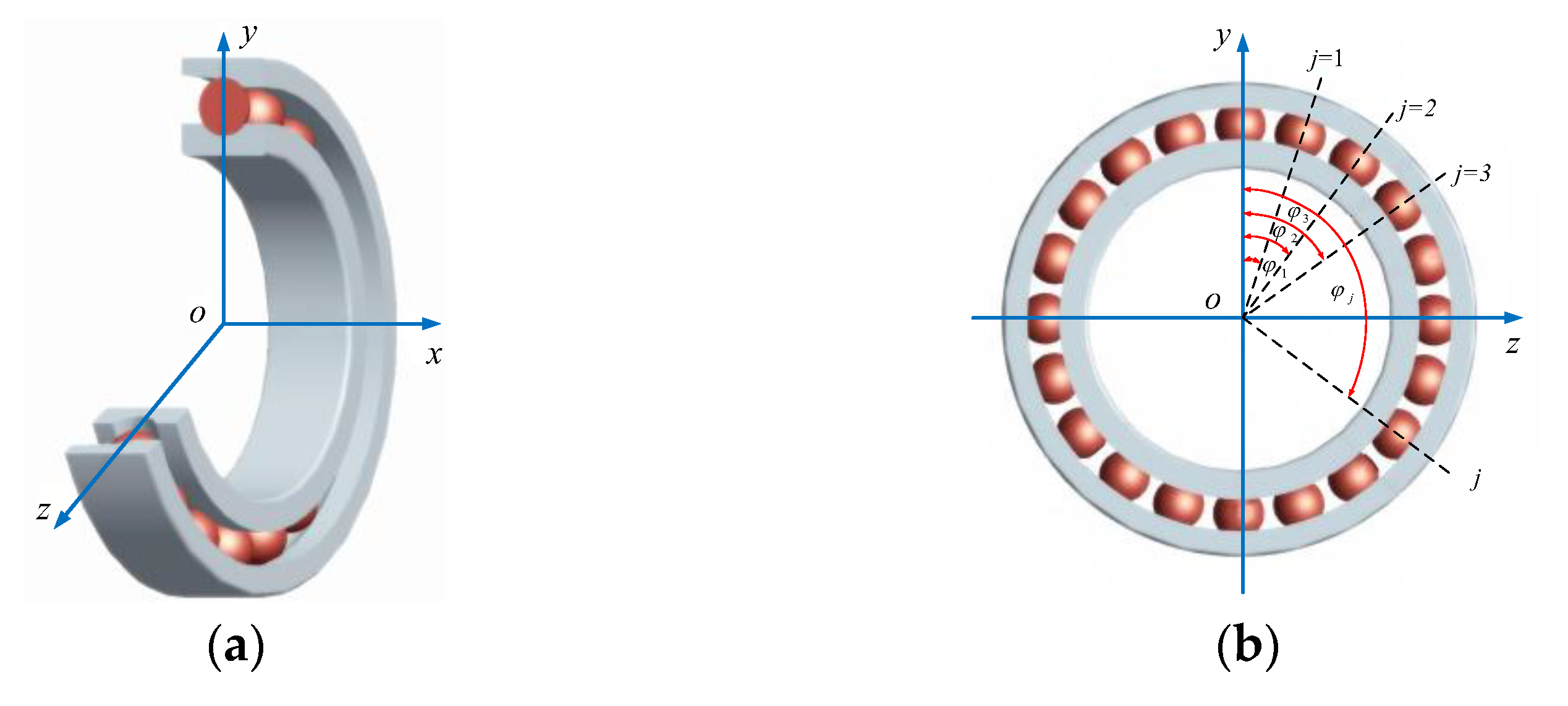
This paper analyzes the position relationship of ACBB in the rectangular coordinate system. As shown in
Figure 1a, the origin
o of the bearing coordinate system
xyz is on the center of the inner ring groove curvature center trajectory circle, the
x-axis coincides with the bearing centerline, the
y-axis is radial, and the
z-axis is determined by the right-hand rule. Simultaneously, the ball azimuth angle is defined as the clockwise angle with the
y-axis in
Figure 1b, and the azimuth angle of the
jth ball is given.
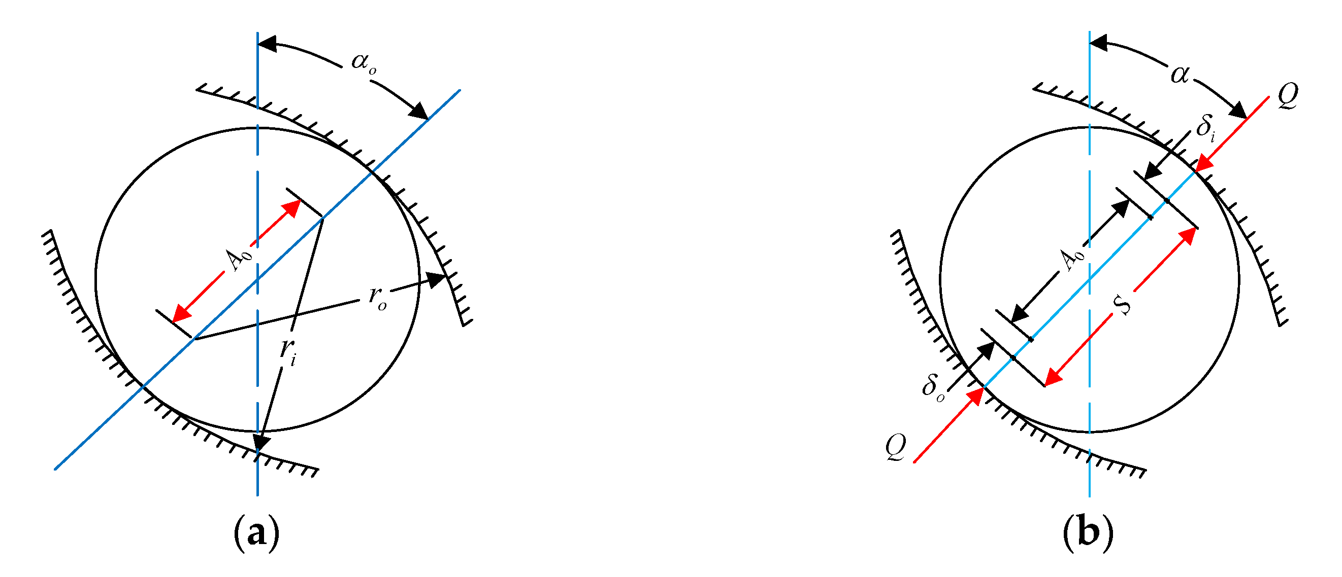
When the bearing operates without being externally loaded, the initial distance between the inner ring’s raceway groove curvature center and the outer ring’s is
, as presented in
Figure 2a, which can be calculated as follows:
Since the groove curvature center is relatively fixed, the ball is externally loaded by the normal force
and the normal limit value of the raceway groove curvature center distance will change accordingly. The relationship formula of displacement and deformation is obtained from
Figure 2b.
The inner ring and outer ring are misaligned due to the slightly poor assembly quality in the actual process of the bearing-spindle assembly, and the outer ring inclines relative to the inner ring (inclination angle is
). Assuming that the inner ring is fixed in space, the outer ring moves respectively in axial and radial directions (the axial displacement is
, the radial displacement is
) in the radial plane of bearing, under known external combined axial and radial loads (the axial force is
, the radial force is
), and the trajectory of the bearing groove curvature center changes after being external loaded, as shown in
Figure 3.
The distance
between the ball at any position angle in the circumferential direction and the raceway groove curvature center of the bearing is calculated as follows:
where
is the groove curvature radius of the outer raceway.
According to Equation (4), the total contact deformation between the ball and the raceways under the load is given as the following equation:
where
,
,
.
According to the load–displacement relationship between the ball and the raceway,
Combining Equations (7) and (8), the contact force between the ball at any position angle
and the raceway can be obtained by
The contact angle
between the ball at any position angle
and the raceway under static load can be described as follows:
The normal load
in Equation (9) applied to the raceway is decomposed into two components along the axial and radial, respectively, which are balanced with the external axial load
and radial load
, and the static equilibrium equations can be expressed as follows:
By substituting Equations (9) and (10) into the above equilibrium equations, for the bearing model considering outer ring inclination due to the misalignment between the inner and outer rings, the axial and radial displacements can be solved by the iterative method. After obtaining the displacement results, the ball-raceway contact load and contact angle at any position angle can be calculated accordingly, and the results will be used as the initial value of the quasi-static analysis.
3. Quasi-Static Analysis Model of Ball Bearing
The distance between the inner and outer raceway groove curvature centers is
, as shown in
Figure 2a, in the absence of external load, while the distance is
under external loads and the raceway groove curvature centers are still collinear with the ball center, as shown in
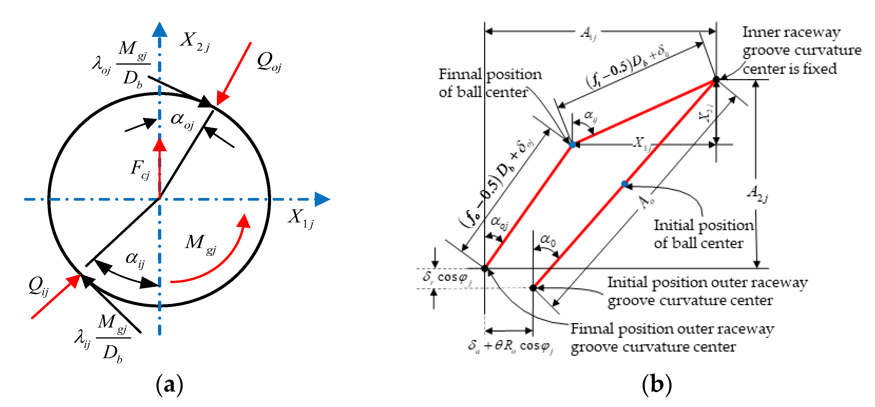
Figure 2b. However, as shown in
Figure 4a, when the bearing works at high speed, the ball is subjected to complex loading combinations, including centrifugal force
caused by a high level of rotation, gyroscopic moment
induced by the spin of the ball, and ball-raceway normal contact forces
and
. Because of the centrifugal effect, the ball-raceway contact angle varies; consequently, the inner raceway groove curvature center moves and the raceway groove curvature centers will not be colinear with the ball center anymore, as shown in
Figure 4bIn this article, the model has been developed imposing the inner ring is fixed while the outer ring displaces in the global coordinate system.
Figure 4 shows the displacement relationship and as the ball center moves due to the centrifugal effect, the outer and inner raceway contact angles are no longer equal.
The final distances between the
jth ball center and the raceway groove curvature centers, respectively, are described as
where
and
are normal contact deformation between the ball and the inner and outer raceways.
After analyzing the relative axial displacement
, relative radial displacement
, and relative inclination angle
of the inner and outer ring, the axial distance
and the radial distance
between the inner and outer raceway groove curvature centers at position angle
can be written as
In order to facilitate the analysis, the variables
and
are introduced. Combining the Pythagorean theorem, the following equations can be deduced by analyzing the position relations in
Figure 4b:
In addition, it can be observed that at the position of the
jth ball,
When the centrifugal force
, gyroscopic moment
, and contact forces
,
act on the ball simultaneously, the forces applied to the ball in both the horizontal and vertical directions satisfy the following equilibrium relations:
As the ball bearing operates at high speed, the ball-outer race friction increases while the ball-inner race friction decreases, and the characteristics are close to the outer race control assumption, that is, the gyroscopic moment caused by the spin motion of the ball relative to the outer race will be prevented by the friction between the two (they are relatively pure rolling); therefore, .
Then, the centrifugal force and the gyroscopic moment of the
jth ball can be expressed as
where
and
denote the orbital revolution and spinning angular speeds of the ball, respectively.
is the ball pitch angle.
In order to determine the relations between the bearing displacements
,
and the external loads
,
, under the condition that the outer inclines relative to the fixed inner ring, the equilibrium equations of outer ring are listed as follows:
Meanwhile, the bending moment
of the bearing is calculated as follows:
So far, the numerical analysis of quasi-static of the rolling bearing has been completed by solving Equations (16), (18), (21) simultaneously, the relevant characteristics parameters including ball-raceway contact angles and contact loads, axial and radial displacements of outer ring will be obtained.
4. Heat Generation Calculation of Ball Bearing
Taking angular contact ball bearing (NSK7014C) as research object, the specific working conditions that the external axial load Fa = 1400 N, external radial load Fr = 100 N and bearing speed n = 2000–8000 rpm are set. According to the comprehensive sample handbook for rolling bearing products offered by NSK Ltd., for the inclination of the outer ring due to the poor assembly quality, the allowable angle error for the installation tilt between the inner and outer rings of precision bearing is generally within 0.069°. In order to avoid abnormal working conditions, such as the obvious inclination with a large angle of the outer ring, this article focuses on the force and temperature characteristics of precision bearing in the case where the outer ring is slightly inclined. Therefore, the tilt angles of the outer ring are selected as 0°, 0.0052°, 0.0104°, 0.0156°, 0.0208° respectively.
The characteristics of the contact force between the bearing ball and the ring at different speeds are analyzed, and the results show that the variation law of the internal contact force with the bearing speed is very similar. Therefore, the bearing operation speed is set at 8000 rpm to analyze the ball-raceway contact angles and contact forces in the state of different tilt angles of the outer ring.
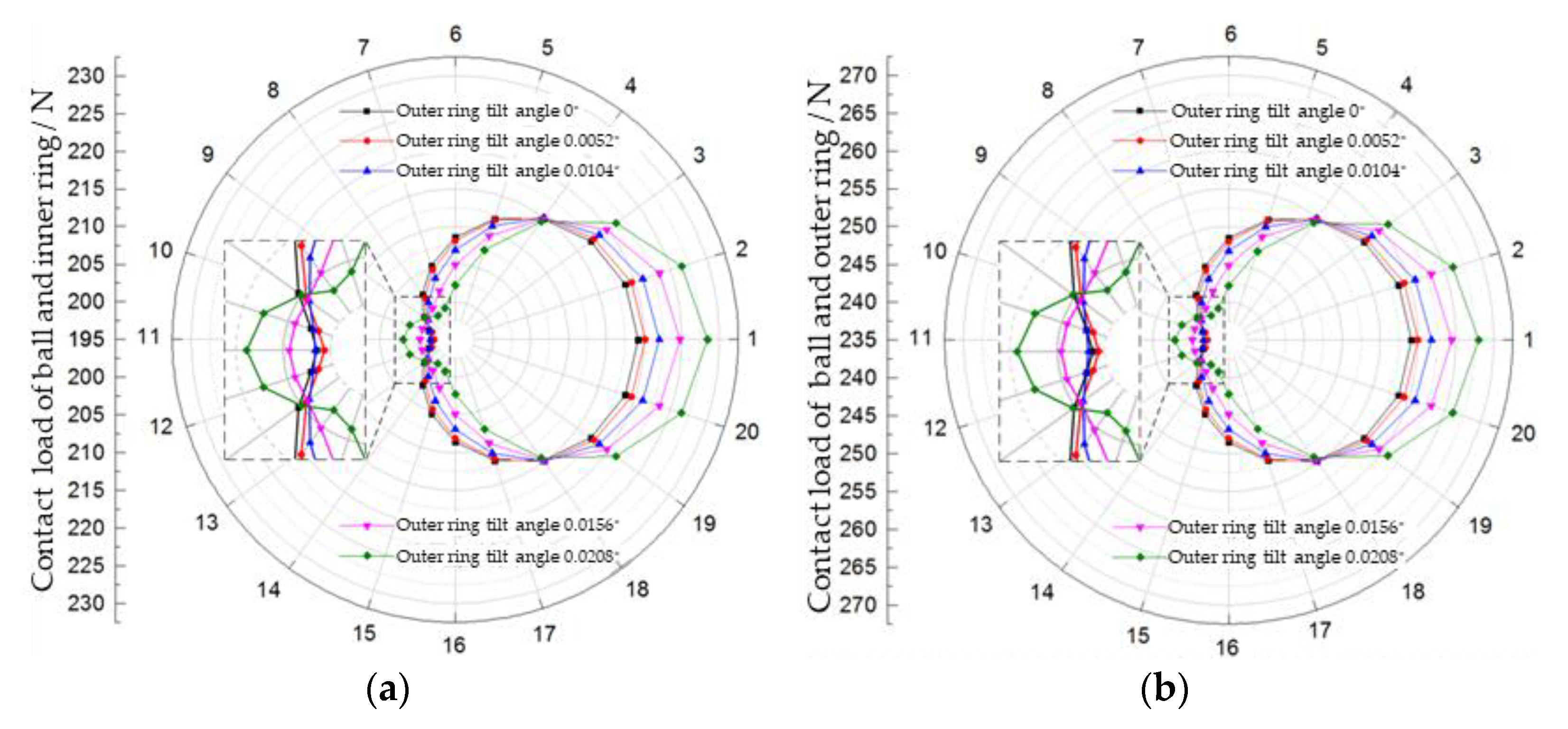
In order to characterize the ball forces and operating state at any position angle, the ball-raceway contact conditions are plotted in a polar coordinate system, the ball-raceway contact load distribution is shown in
Figure 5, and the ball-raceway contact angle distribution is shown in
Figure 6. The circumferential direction is the bearing ball number, and the radius direction is the simulation result value of each calculated quantity.
As shown in
Figure 5, the polar coordinate circle diagram shifts to the right as a whole, as the outer ring inclination angle increases, that is, the ball-raceway contact forces increase along the radial direction of force applied to the outer ring. At the same time, it can be observed from the local magnification view that in the opposite direction of the radial force applied to the outer ring, the ball-raceway contact forces at first slightly decrease and then slightly increase, as the outer ring inclination angle increases. As shown in
Figure 6, when the inclination angle of the outer ring is zero, the ball-raceway contact angles are approximately constant, presenting a regular circle located in the center of the polar coordinate system, while the polar coordinate circle diagram shifts to the right as a whole, as the outer ring inclination angle increases; the ball-raceway contact angles increase along the radial direction of force applied to the outer ring, whereas the contact angles decrease.
During the bearing operation, the energy loss caused by the internal friction is converted into heat generation. Therefore, the bearing heat generation power is calculated by the friction torque and the rotation speed. Subsequently, the influence factors of bearing friction torque mainly depend on the type, size, load, rotation speed, characteristics and supply of lubricant and so on. Firstly, Palmgren and other scholars performed a large amount of experimental studies, then analyzed the bearing thermal performance under the conditions of different loads with light, medium and heavy states, different lubricant methods and different lubricant media and finally derived the empirical formula for bearing friction torque. Therefore, the empirical formula has a reference function to some extent under the low-speed operation conditions, while the heat generation calculation needs to be improved under the high-speed operating conditions.
The empirical formula for bearing friction torque proposed by Palmgren contains the following two parts: the friction torque
caused by lubricant viscosity and the friction torque
caused by contact loads. However, due to the centrifugal effect during the bearing high-speed operation, the changes in ball-raceway contact characteristics occur, which leads to the ball-raceway contact friction torques’ variation. At the same time, the friciton torque differs at different position angles. Therefore, in the calculation process, it is necessary to split the bearing friction torque into the inner and outer rings’ components, then transform them into local components of local contact area at each position angle, demonstrated by the following equations:
Similarly, the frictional heat generation caused by the ball spinning motion cannot be negligible during the bearing high-speed operation, and the ball-raceway spin friction moments within the contact regions are given by
where
and
denote the friction coefficient between the balls and inner and outer raceways,
and
represent the semi-major axes of the elliptical projected area of contact between the balls and inner and outer raceways;
and
are the complete elliptic integrals of the second kind, respectively.
The power loss is related to friction torque and rotation speed, the heat generation within every contact region can be obtained by multiplying friction torque and rotation speed and the total heat generation of bearing is given as
where
and
are the angular velocities of rolling of the ball with respect to the inner and outer race,
and
are the angular velocities of spin of the ball with respect to the inner and outer race, respectively.
and
are expressed as follows:
where
and
are the relative angular velocities of balls with respect to the inner and outer raceways (bearing axis as a reference).
By the establishment of the model for heat generation prediction in angular contact ball bearing, the local and total heat generation of the bearing are obtained with different rotation speeds and diverse outer ring parallelism errors, so as to investigate the influence of outer ring inclination on bearing thermal characteristics.
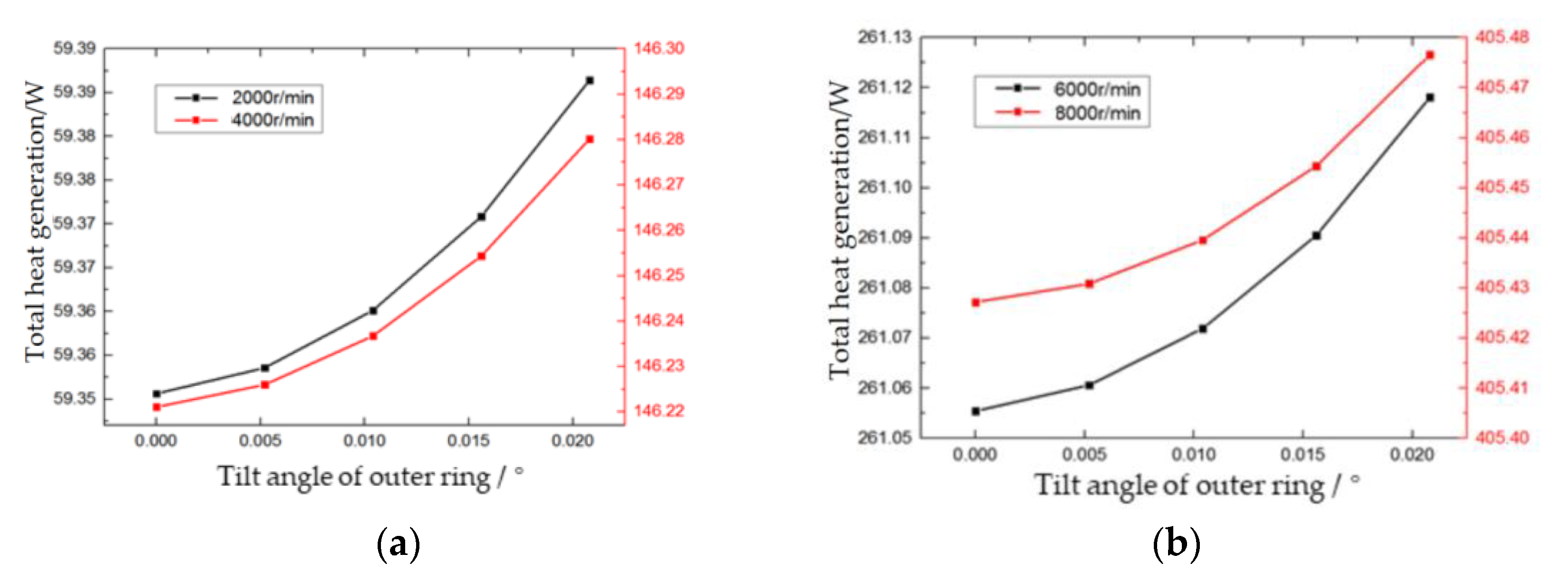
Figure 7 shows the effect of the outer ring inclination on the total heat generation of bearing as the rotation speed varies. That is, the heat generation of the bearing shows a curve change at different speeds. This is because as the speed increases, it can be observed from the empirical formula that the friction torque, caused by the viscosity of the lubricating medium, increases exponentially with the speed change, resulting in a change in the curve in
Figure 7.
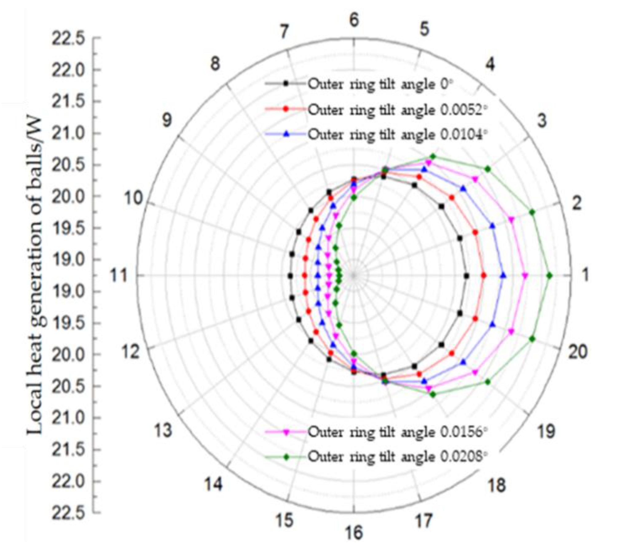
Figure 8 shows the distribution of local heat generation of each ball at 8000 rpm.
It can be observed from
Figure 8 that the variation tendency of local heat generation of the ball is consistent with the variation tendency of the contact angles, which means that with the increase in the outer ring tilt angle, the heat generation in the radial direction increases. While the heat generation decreases in the opposite direction of the radial force, in the direction perpendicular to the radial force, it is constant. In addition, the heat generation of the angular contact ball bearing shows a slight increase with the increase in the outer ring tilt. The increment of total heat generation is small with the increase in tilt angle at the same speed and is almost unchanged, which indicates that the inclination of the outer ring has little impact on the total heat generation of the bearing. The total heat generation of the bearing is mainly affected by the rotation speed; as the speed increases gradually from 2000 rpm to 8000 rpm, the heat generation tends to increase progressively by double with each 2000 rpm increase, meanwhile, the increase rate slows down gradually.
When the bearing is subjected to external loads, the outer ring inclination will lead to uneven heat generation in the local contact area at each position angle inside the bearing. When the spindle runs at a constant speed of 8000 rpm, the relative tilt angle of the outer ring increases from 0° to 0.0208°, the heat generation at different locations differs by 2.7 times, and the heat generation in the upper half of the bearing is larger than that in the lower half.
5. Experiments and Discussion
It can be observed from the above calculation that, with the impact of outer ring non-parallelism, the heat generation at different positions in the circumferential direction inside the bearing differs significantly, and the difference is more pronounced as the rotation speed increases. However, due to the limit of testing technology for rotating components inside the bearing, it is difficult to verify the effect of the ring non-parallelism on heat generation through the temperature test of the inner ring directly, while it is also difficult for the traditional outer ring temperature measurement to reflect the difference in temperature rise directly, due to the influence of the complex heat transfer process inside the bearing. In this regard, this paper attempts to measure rotary accuracy variation induced by expansion and deformation of the bearing under different heat generation conditions, to indirectly verify the effect of ring non-parallelism on the thermal characteristics of the bearing.
5.1. Description of the Precision Bearing Test-Rig
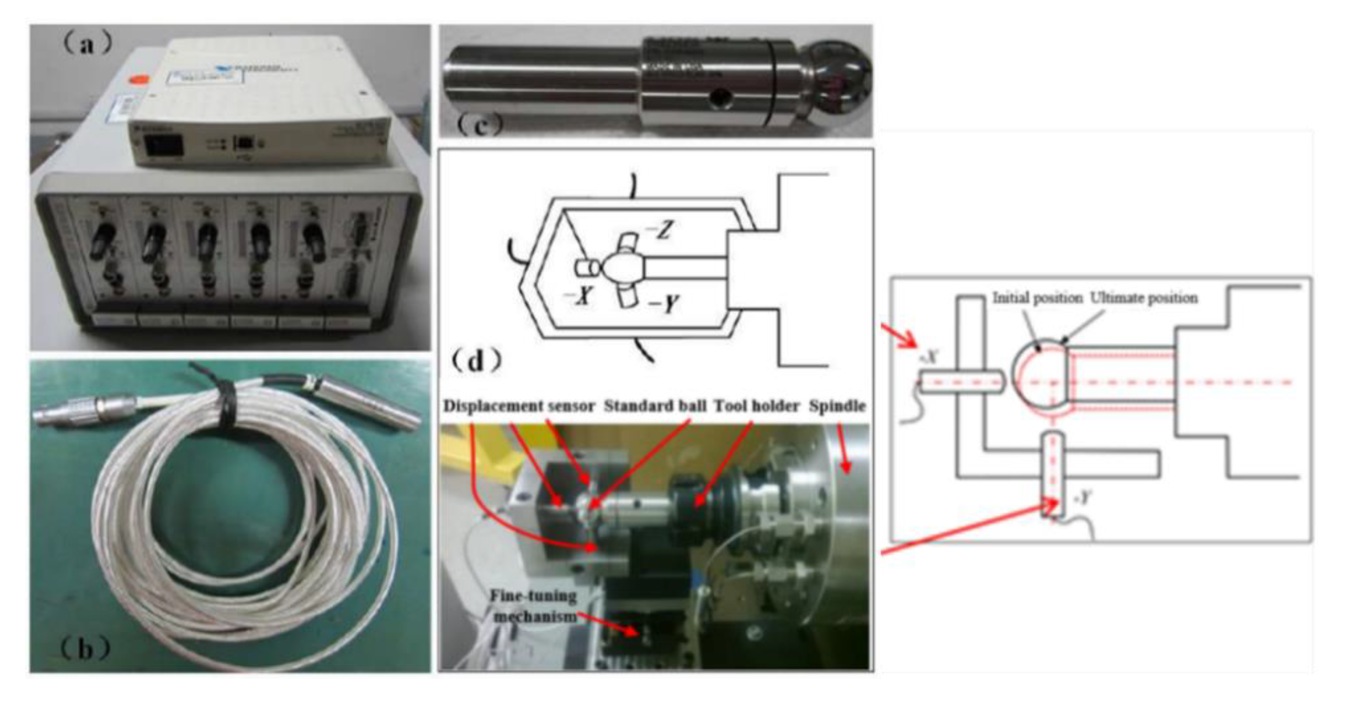
The experiment platform in this study adopts the WZ15B90-30SE precision spindle provided by NSK Ltd. (Tokyo, Japan), the built-in tool shank specification for the BT40 broaching mechanism and the highest experimental rotation speed can reach 8000 rpm. The bearing type is 7014CTYNSULP4, grease lubricated (during the bearing operation, bearing grease and grease dosage were selected by referring to the bearing manual of NSK), and installed on the spindle in the configuration of DBB. The motor is an SJ-V7.5-03 ZM AC spindle motor manufactured by Mitsubishi Group, and the spindle is driven by the belt. The spindle thermal displacement test experiment selects the spindle error analyzer produced by Lion Precision, Oakdale, MN, USA, and the analyzer obtains the thermal displacement data of the front end of the spindle by measuring the displacement change in the standard ball (bar) fixed on the spindle front through the capacitive displacement sensor. The standard ball is 25.4 mm in diameter, 50 nm in maximum roundness error, 20 mm in diameter at the clamping end, clamped and fixed in the tapered hole at the front end of the spindle using a BT40 × ER32-70 tool holder. The capacitive displacement sensor test heads are respectively mounted in the −X, −Y, −Z directions in
Figure 9, and the three directions indicate the horizontal radial, vertical radial, and axial coordinate directions, with the standard ball center as the coordinate center, which is consistent with the coordinate system setting of the previous theoretical analysis in this paper. The C8-2.0 capacitive displacement transducer is set to the standard measurement range (250), the bandwidth is set to 1 kHz (resolution 1.4 nm), and the sampling frequency is 360 Hz. Before the formal test, the standard ball is clamped to the front end of the spindle by the tool holder, and then the displacement transducer is installed at the corresponding measurement position and adjusted to the center on the standard ball using the fine adjustment mechanism.
5.2. Analysis of Trajectory and Accuracy Error of Spindle Rotation
The test simulates the different outer ring balance degrees of the bearing by adjusting the end face parallelism error of the short outer spacer inside the mechanical spindle system, and then investigates its effect on the performance of the shaft system. In the experimental simulation, bearing spacers with five tilting angles of 0°, 0.0052°, 0.0104°, 0.0156°, 0.0208° were machined, respectively.
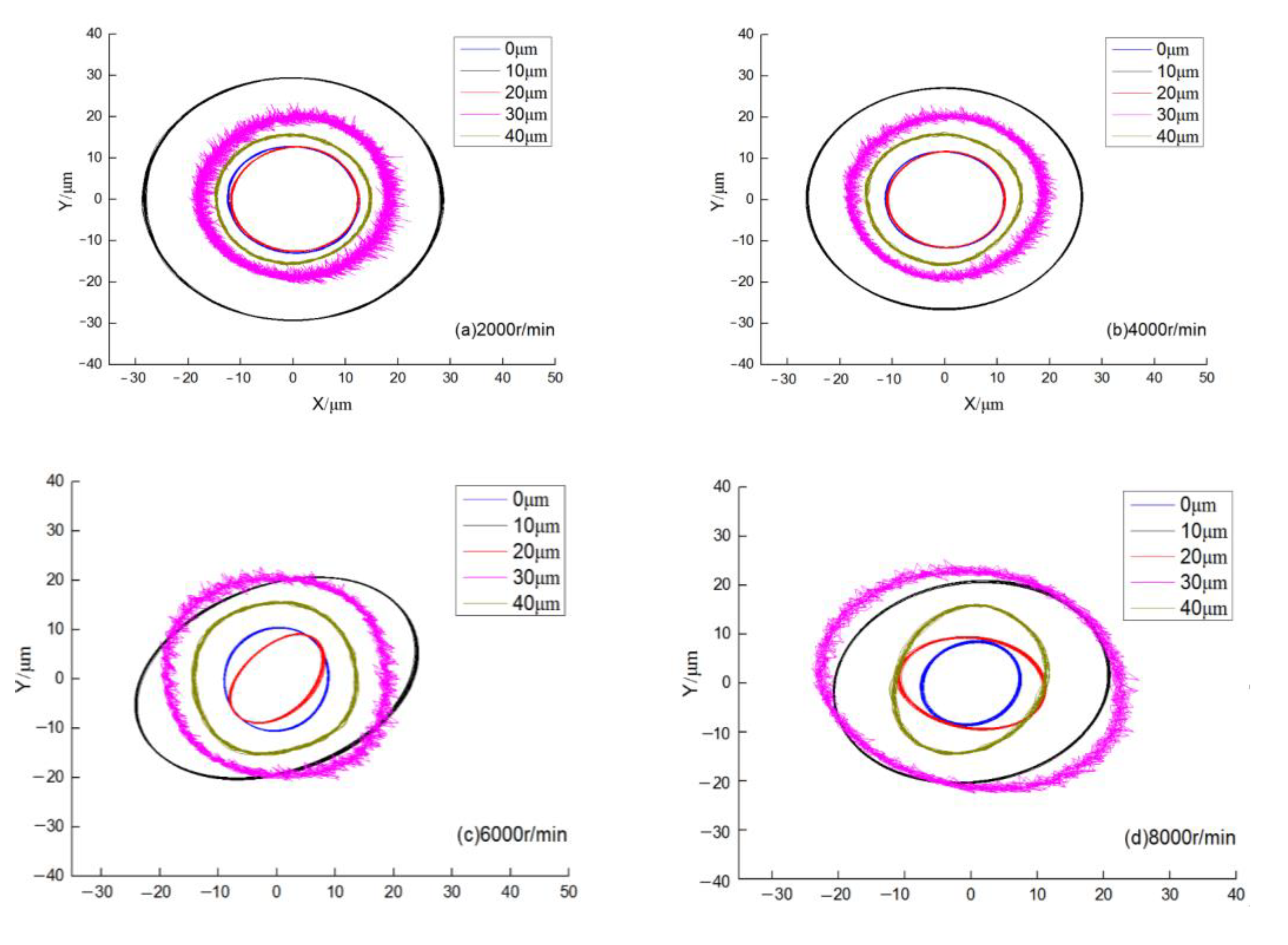
After the spindle rotates and the temperature data reach a stable value, the radial X and Y channel displacement signals are collected and recorded, and the spindle rotation trajectory is plotted at each speed, as shown in
Figure 10.
As can be observed from
Figure 10, the spindle rotation trajectory is in the best condition when the outer ring is not tilted. When the outer spacer parallelism is poor, the spindle rotary trajectory becomes worse, both in terms of roundness and radial runout. The TIR (total indicated runout) value of the spindle front end in both radial directions increases, the rotary trajectory expands, and the width of the spindle front end runout trajectory becomes larger accordingly, which shows that the outer spacer parallelism error causes uneven heat generation inside the bearing and tilt deformation, and immediately results in an increase in the NRRO (non-repeatable runout) value at the spindle front end. However, it can be observed that the slewing accuracy does not completely increase with the increase in the outer ring unbalance, and the slewing accuracy shows the phenomenon of interval runout. In addition, it can be observed from the above analysis that in the heat generation calculation of different inclinations of the bearing outer ring, the uneven heat generation of the bearing is more obvious as the inclination increases, which shows a certain linear relationship. However, in the experiment of spindle rotation accuracy under different outer ring inclinations, it is found that the rotation accuracy of the spindle is the best when the outer ring is not inclined. However, with the increase in outer ring inclination, the rotation accuracy does not have a similar linear relationship. This is because, for a precision spindle, its rotation accuracy is jointly affected by many factors, such as thermal deformation of the bearing, shaft structure, and modal frequency, etc.
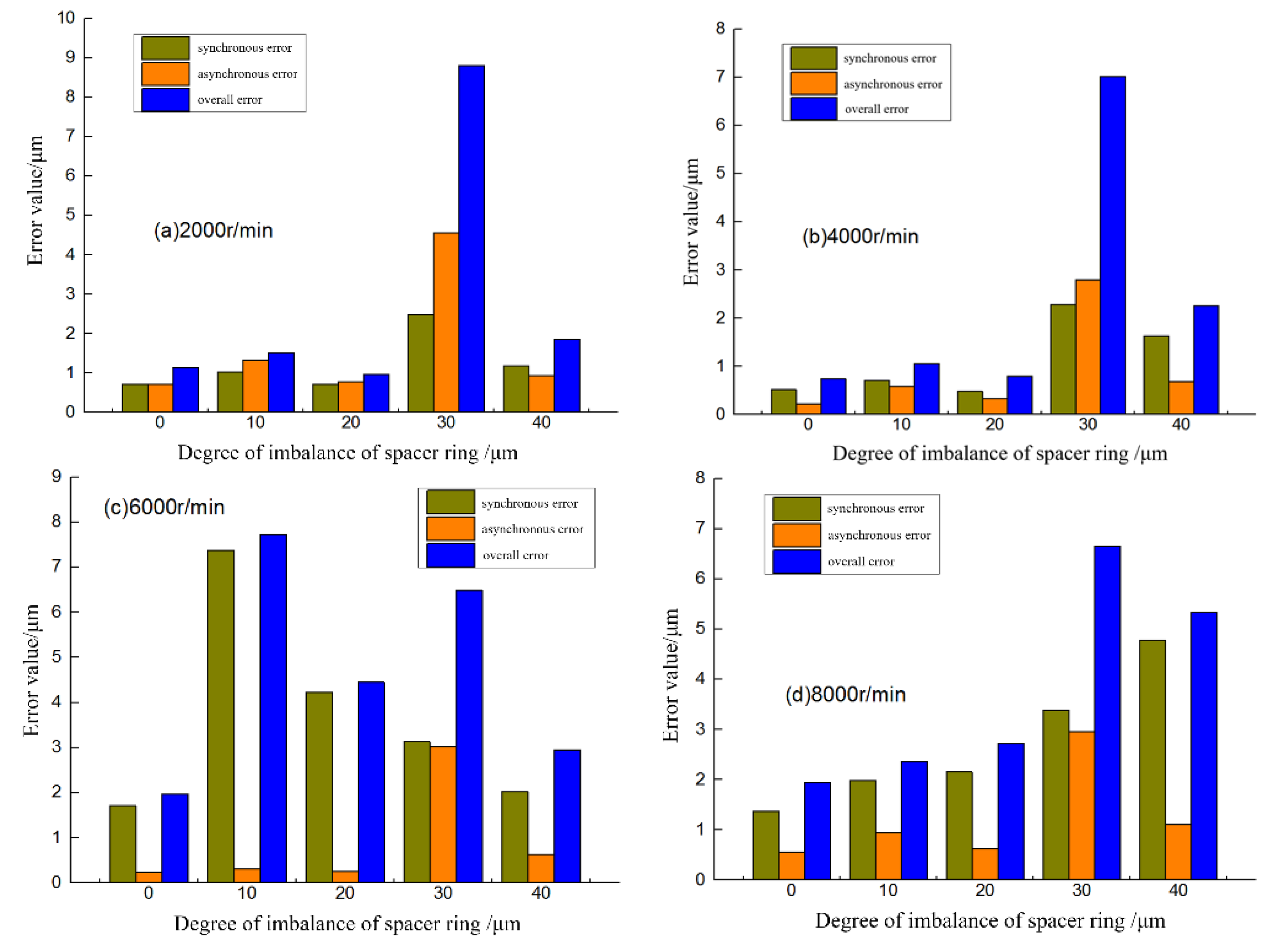
The quantitative analysis results of the spindle-related motion errors can also be obtained from the rotary error calculation, as shown in
Figure 11 below, which compares the spindle motion error values under each spacer accuracy type.
As can be observed from the above figure, the spacer parallelism error causes uneven heat generation in the circumferential direction of bearing and tilt deformation, which will lead to the deterioration of rotational accuracy of the spindle front end, and the impact is relatively small at the rotation speed of 2000 rpm and 4000 rpm, while the impact is great at 6000 rpm and 8000 rpm. In contrast, the outer ring unbalance has a greater impact on the spindle synchronization error, especially at higher speeds. However, further analysis shows that the rotation accuracy of the spindle front end is worse than other working conditions with the 0.0156°(30 microns) inclined spacer and at 6000 rpm, which may be because at this moment, the spindle is close to its natural vibration mode, resulting in inconsistency with other rotational speeds. At the rotation speeds 2000 rpm, 4000 rpm, and 8000 rpm, it can be observed that as the inclination of the bearing outer ring gradually increases from 0 to 0.0052°(10 microns), 0.0104°(20 microns) and 0.0208°(40 microns), the rotation accuracy of the spindle deteriorates, which indirectly verifies the effect of bearing ring inclination on its internal heat generation.
