1. Introduction
Owing to the characteristics of low friction and high precision, ball bearings are widely used in rotational systems, such as high-speed motors, precision machine tools and aero engines [
1,
2]. Regarding the complex internal structure of the bearing, relative motion and force conditions, etc., there are complex tribological behaviors between balls and inner/outer rings, which may cause bearing friction heat and power loss, and even accelerate bearing wear and reduce bearing operation accuracy, etc. [
1]. Therefore, the bearing friction phenomenon hinders the further improvement of high-speed bearing performance [
3]. Especially with the continuous improvement of energy consumption requirements of rotating equipment, the design of low-friction bearings has become a current research hot topic. It is preferred to analyze the various complex sources of bearing friction, such as the structural constraints, and to reduce their sizes in a targeted manner by improving the structural and external operating conditions. Accurate computation of bearing friction loss, operating in complex motion and force conditions, has become a prerequisite for this research.
Since the middle of the 20th century, the frictional properties of bearing are investigated by few scholars. Under different working conditions, the friction torque of different types of bearings was experimentally tested by Palmgren et al. [
4,
5]. The empirical formulas of bearing frictional torque were proposed based on the experimental data. However, the friction model by these empirical formulas is mainly suitable for light load and low speed conditions. Besides, the famous bearing company SKF proposed a set of models for calculating bearing frictional torque also based on experimental dates [
6]. Compared to the former, the model accuracy has been improved, while it is mainly used for bearings in standard installation and standard load condition. With an experimental method, the influence of the raceway curvature radius on the frictional torque of angular contact ball bearings was experimentally analyzed by Todd et al. [
7]. Similarly, Rodionov [
8] studied the effects of surface finish quality on bearing friction torque and it showed that, compared with the surface finish quality of rings, the rolling element significantly affected the friction torque. With the development of data processing methods, some new methods were applied to the study of bearing friction torque. Based on statistical correlation theory, the parametric-nonparametric fusion method was used to analyze the bearing friction torque by Xu [
9]. By measuring the friction torque, Zhang et al. [
10] modeled the data with gray theory to predict bearing friction torque. By summarizing the above work, it can be found that the present friction torque models were all based on experimental methods and dates, and then the overall friction performance of the bearing was investigated. However, the bearing friction torque is actually affected by many factors inside the bearing, such as bearing structural parameters, motion characteristics, load distribution etc. Especially for ball bearing, the ball’s revolution, spin, gyro and other motion forms will affect its friction performance.
Snare, Li and Wang et al. [
11,
12,
13] pointed out that the friction inside the bearing mainly comes from the elastic hysteresis, differential sliding, spinning, and friction agitation. Ye et al. [
14] established a simple friction model for bearing in steady state. The differential sliding and spin friction were considered while the complex motion in the contact area was ignored. In order to explore the influence of the movement of the contact area on the friction performance of the bearing, by energy conservation law, the solution results of the mechanical model were used to calculate the friction torque by Deng [
15]. The results show that the complex motion of the contact zone, such as balls sliding in the contact zone, has an important impact on the friction loss. On the basis of the above studies, Todd et al. [
16] used the micro-slip theory to determine the pure rolling line in the contact zone. Then the frictional resistance was solved by integrating the complex motion of the contact zone. Unfortunately, the friction torque model and mechanical model are unidirectionally coupled, thus the effect of friction torque on bearing internal motion is missing. Houpert et al. [
17] analyzed the motion of the contact zone and obtained the pure rolling line between ball and raceway. Then, the integral of the contact zone was calculated to obtain the contact friction. Finally, the bidirectionally coupled friction torque was achieved based on Cao’s quasi-static model [
18]. Because of the implementation of bidirectional coupling and the refinement of the contact zone, an obvious change of the friction results was observed. It indicates that the complex contact behavior between bearing components has a significant impact on its total friction loss. Therefore, it is necessary to study the internal friction characteristics of the bearing parts.
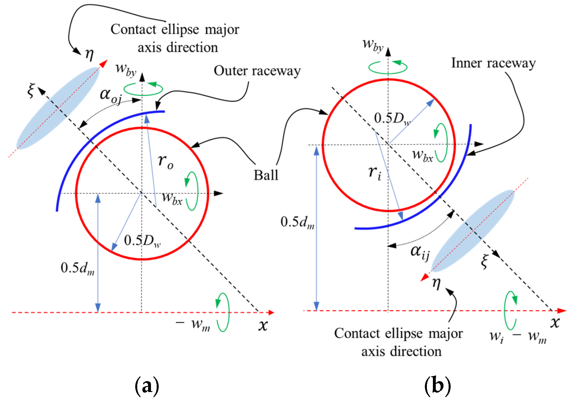
For bearing internal friction analysis, the current research mainly focuses on the steady-state friction. That is, the total friction is generated by the complex motion in the contact zone between the bearing parts, such as differential sliding and spin friction, etc. As mentioned earlier, due to the motion of the ball in the ball bearing being particularly special, the friction induced by the revolution is disregarded when the rolling elements move in the circumferential direction. In other words, the current friction calculation mainly considered the motions between the balls and the rings along the contact ellipse minor axis, while the sliding friction along the major axis is ignored [
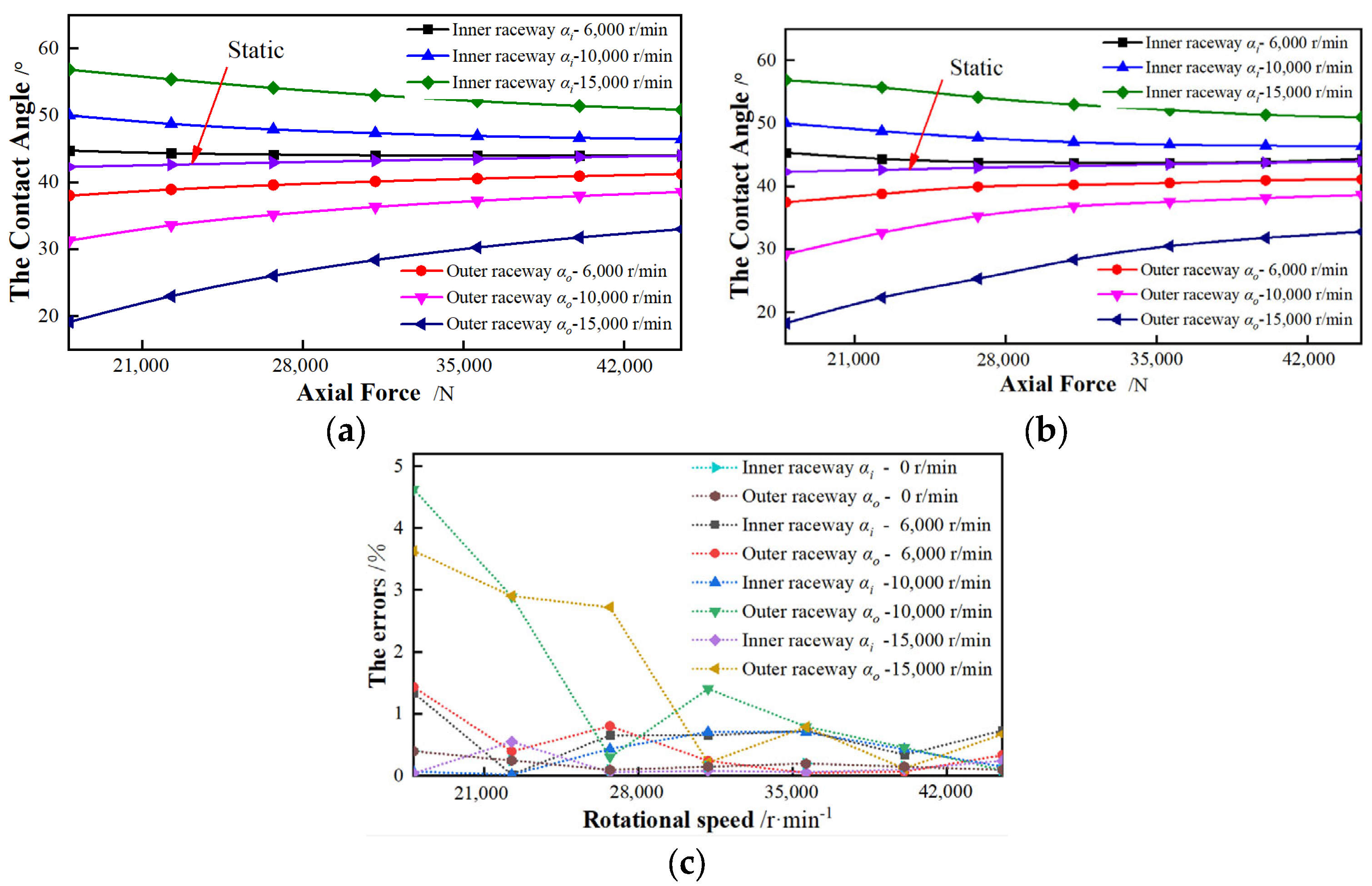
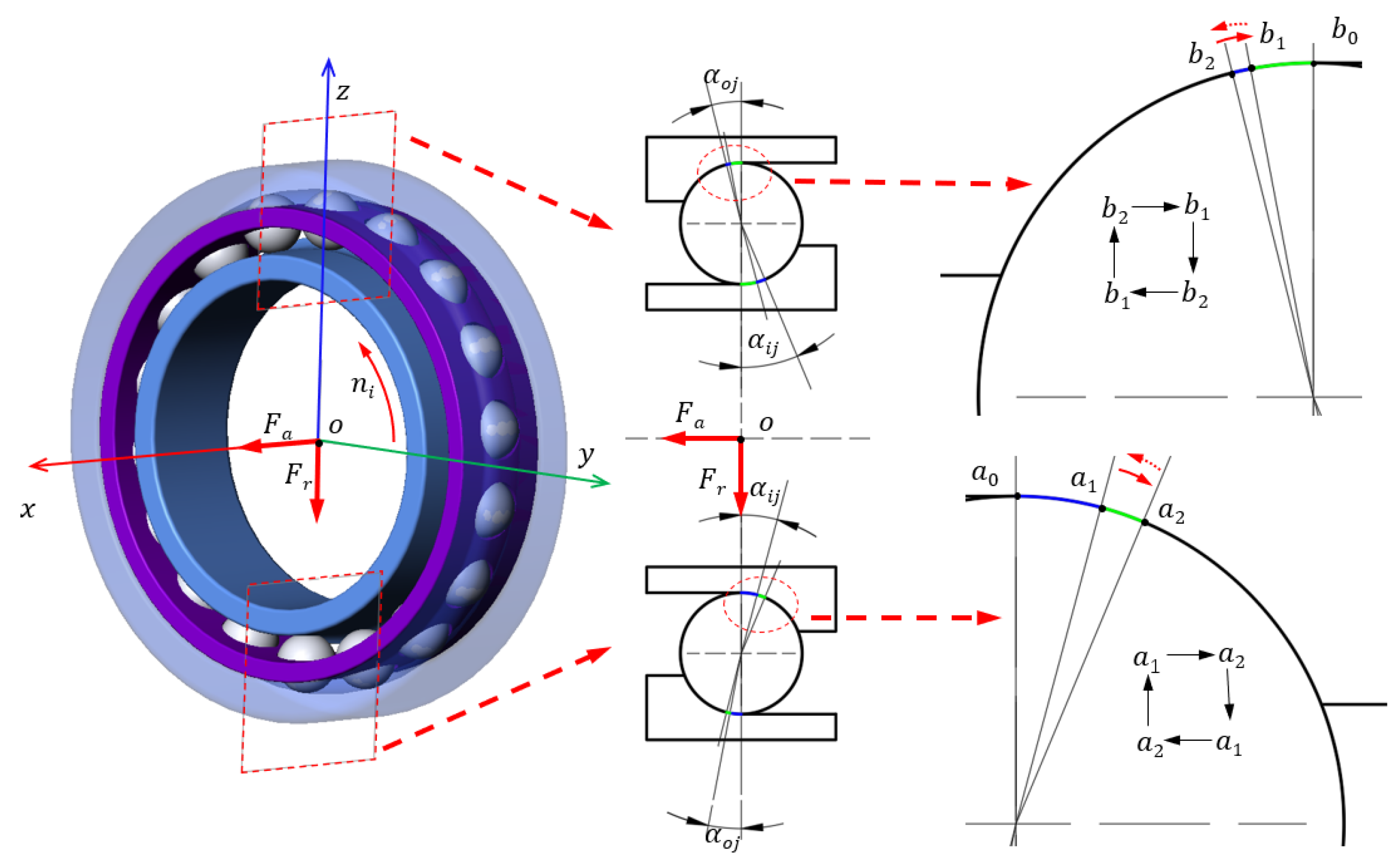
19]. In fact, in conditions of high speed and combined load, the internal forces of the bearing become very complicated. In addition to the friction caused by the gyroscopic torque, the friction generated by the contact angle cannot be neglected. Due to the inconsistent force of each rolling element, the contact angle between the balls and the ring is unequal, which is the main cause of the ball slides along the major axis of the contact ellipse during bearing operation. For instance, the technical report of SKF pointed out that a large variation in contact angle has an impact on the bearing friction [
20]. As the ball slides along the major axis of the contact ellipse, the collision force between the cage pocket and the ball increased, which eventually causes the increases of bearing friction. Thus, it is of great significance to investigate the sliding of the rolling element of the bearing along the major axis of the contact zone. In this paper, taking the angular contact ball bearing as the research object, a quasi-static model is established. In condition of the combined load, it is found that the friction caused by the sliding length of the bearing is discussed, such as operating parameters, structural parameters and contact angles.
4. Results and Discussion
Based on the model in
Section 2, a 7008 angular contact ball bearing is taken as the object to be solved. By the sliding length of the ball on the raceway, the friction loss of the bearing with different initial contact angles (15°, 25°) is studied. The efforts of the working conditions and the structural parameters are discussed.
4.1. Radial Loaded Bearing
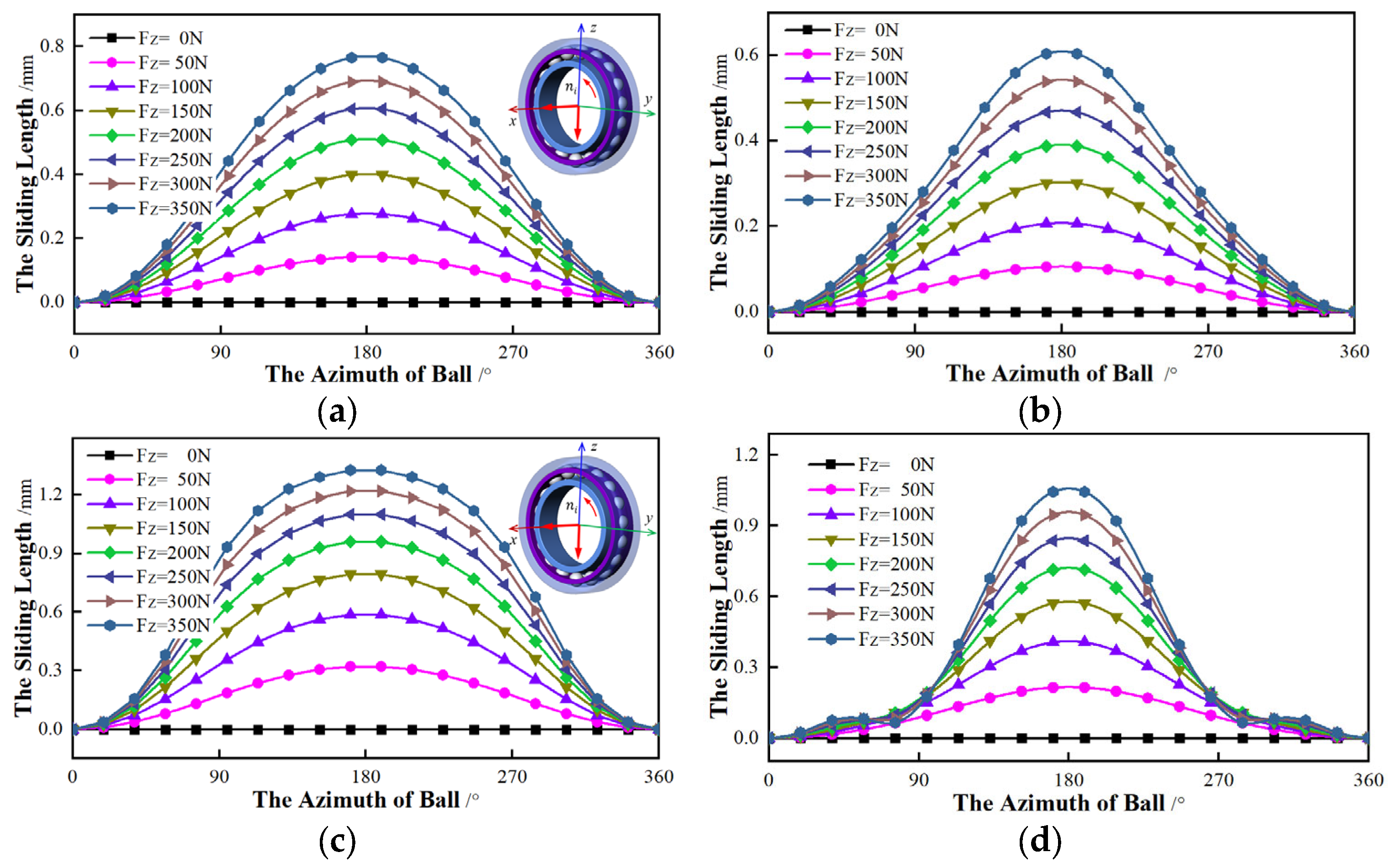
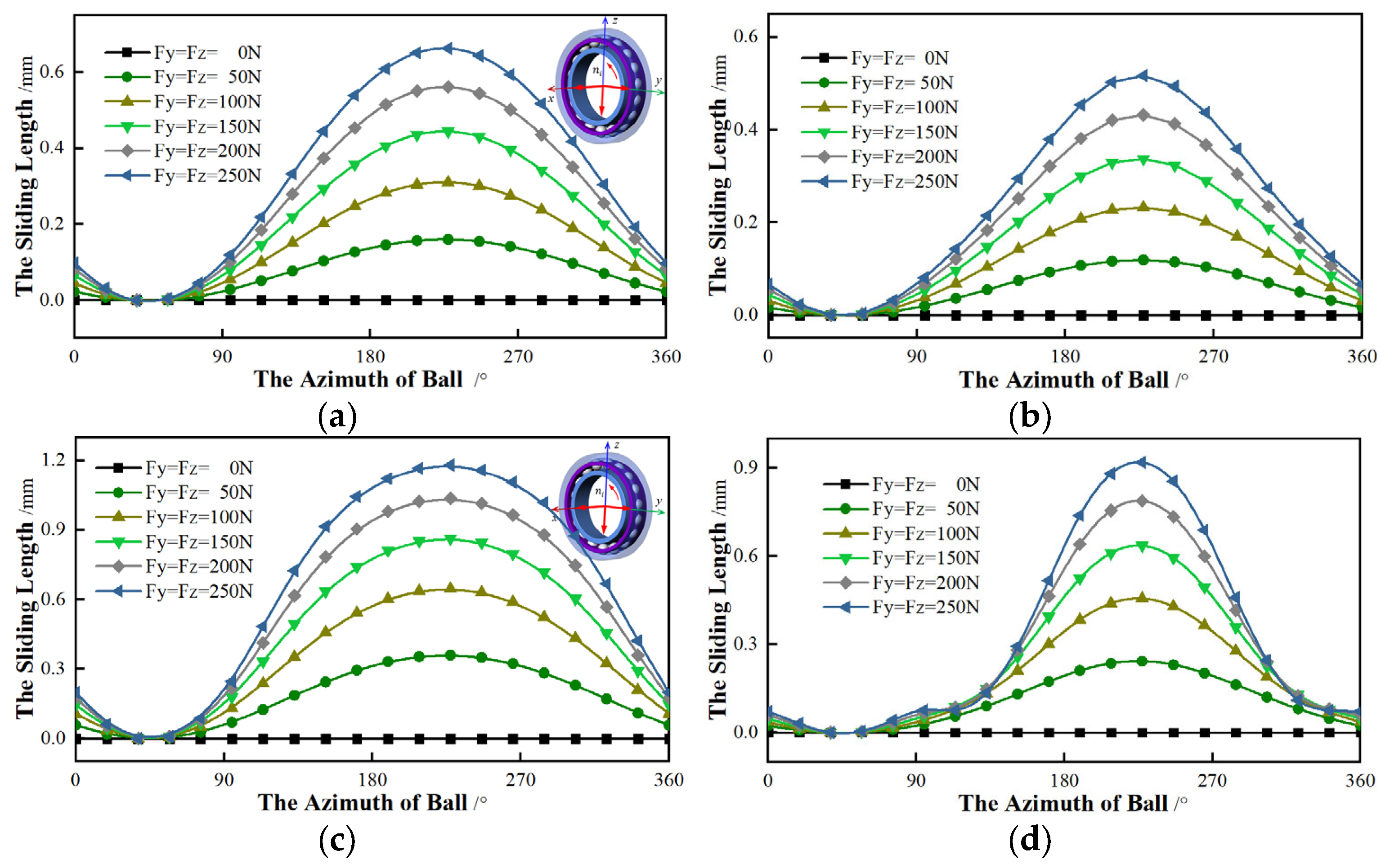
The influence of the radial force on the ball sliding is first studied, including the direction and magnitude. Without the torque (My = Mz = 0 N·mm), a constant axial force (Fx = 500 N) and rotational speed (ni = 10,000 r/min) is considered. By changing the radial force, the trend of sliding with different contact angles is analyzed.
Firstly, the
y-axis is applied to the radial force, while the force of the
z-axis is 0. With the rising of radial force (
Fz) on the
y-axis, the sliding length of the ball with different contact angles is shown in
Figure 11.
The relationship between the sliding length and the radial force is shown in
Figure 9. For bearings with the same initial contact angle, the effect of force is similar. The minimum contact angle (
αmin) appears when the ball is 90°, where the sliding length is 0. The maximum contact angle (
αmax) is located at the ball azimuth of 270°, which is the largest sliding. As the radial force of
Fy grows, the sliding length increases. The variation trend of the sliding is relatively slight when the contact angle of the ball near the
αmin or
αmax. The friction loss is quite small. On the contrary, the trend is relatively sharp in other positions, and the loss becomes large. As for bearings of different initial contact angles, the azimuth angles of
αmin or
αmax are the same. However, the sliding trend of the bearing with 25 ° is larger than that of the 15° under the same force, and the friction loss is also greater. When the ball azimuth closes 45° and 135°, the variation of sliding changes rapidly for the inner, while the larger change for outer appears near the azimuth of 225° and 315°. This means there is more friction.
Secondly, setting
Fy to 0, the
z-axis is applied to the radial force. As shown in
Figure 12, the relationship between the sliding with different contact angles and the radial force is analyzed. No matter whether the initial contact angle is 15° or 25°, the
αmin appears at the position where the azimuth is 0°, and the azimuth of the
αmax is 180°. The other effects of the
z-axis are similar to the force applied in the
y-axis.
Finally, the
y-axis and the
z-axis are applied to the radial force at the same time, which is gradually growing.
Figure 13 shows the relationship between the radial force and the sliding with different initial contact angles and the radial force. It can be found that, regardless of the initial contact angle, the azimuths of
αmin and
αmax are constant and the
αmin appears at the azimuth of 45°, while the 225° azimuth is the
αmax. Other changes have similar effects to the radial force applied to the
y-axis or the
z-axis individually.
To summarize, the sliding length is only affected by the magnitude of the radial force, independent of its direction. With the increasing of the radial force, the variation trend of sliding is increases. However, the direction of the radial force has an influence on the azimuth angles of αmin and αmax.
4.2. Torque Component
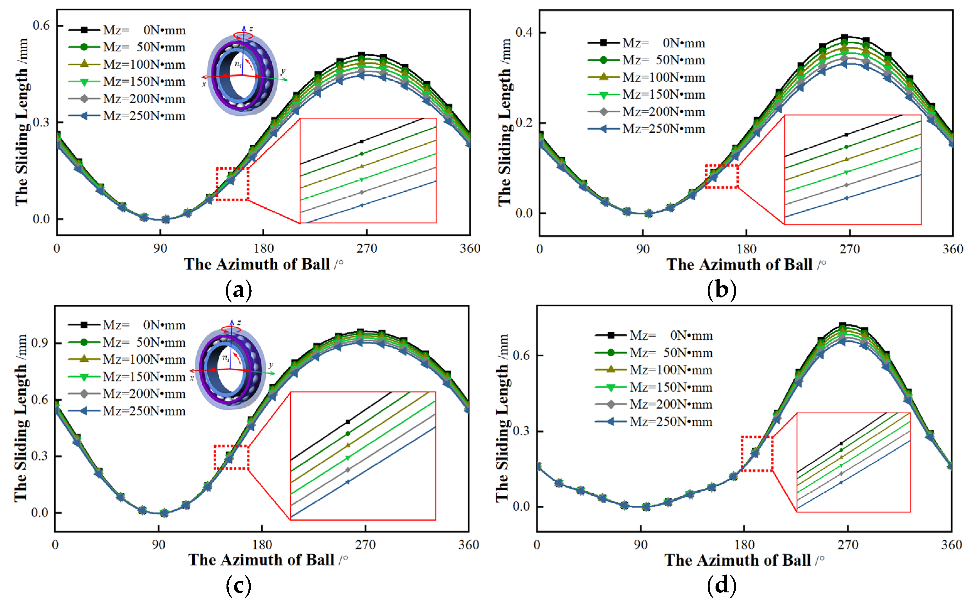
In this section, the relationship between the torque and the sliding is investigated. The axial force (Fx = 500 N), radial force (Fy = 200 N, Fz = 0 N) and rotational speed (ni = 10,000 r/min) are constant. The sliding of different initial contact angles is discussed by changing the torque.
Firstly, the
y-axis is only applied to the torque, which increases from 0 N·mm to 250 N·mm. The torque of the
z-axis is 0. This means that the radial force and the torque are exerted to the same axis.
Figure 14 shows the relationship between the torque and the sliding of different initial contact angles.
From
Figure 14, the difference in sliding of different contact angles is small. As the torque component increases, the azimuth angles of
αmin and
αmax are same and the sliding lengths of different torques are almost equal. Although the sliding rate grows with the increase of torque, the effect is small. For bearings with different initial contact angles, the influence of torque on the sliding is not obvious. The sliding of an initial contact angle of 25 ° is slightly less sensitive to this torque than that of 15 °. From
Figure 14, we can see that the total sliding length of a larger initial contact angle is greater than the sliding of a small contact angle.
Secondly, the
z-axis applied to the torque is considered, which is gradually rising. In other words, the radial force is applied to the
y-axis while the
z-axis exerts to the torque. The relationship between the torque and the sliding length of different initial contact angles is shown in
Figure 15.
As shown in
Figure 15, this type of torque has an influence on the sliding length of the bearing with the same initial contact angle. As the torque rises, the sliding length gradually decreases and the azimuth angles of
αmin and
αmax are constant. As for the variation rate of sliding, it also gradually reduces. With regard to bearings with different initial contact angles, the variation rates are distinct. The rate of bearings with an initial contact angle of 15° is more sensitive to torque than the rate of 25°. However, the total sliding length of the 25° is generally greater than that of the 15°.
In summary, when the torque and radial load are applied to the same axis, the effect of torque on sliding is very weak. On the contrary, applying the torque and radial load to the different axes, the torque has a corresponding effect on the sliding. With the torque increasing, the sliding length gradually lessons. From
Figure 14 and
Figure 15, regardless of whether the torque and the radial force are on the same axis, the sliding lengths of different initial contact angles are unequal and the sliding with an initial contact angle of 25° is always greater than that of 15°.
4.3. Rotational Speed Bearings
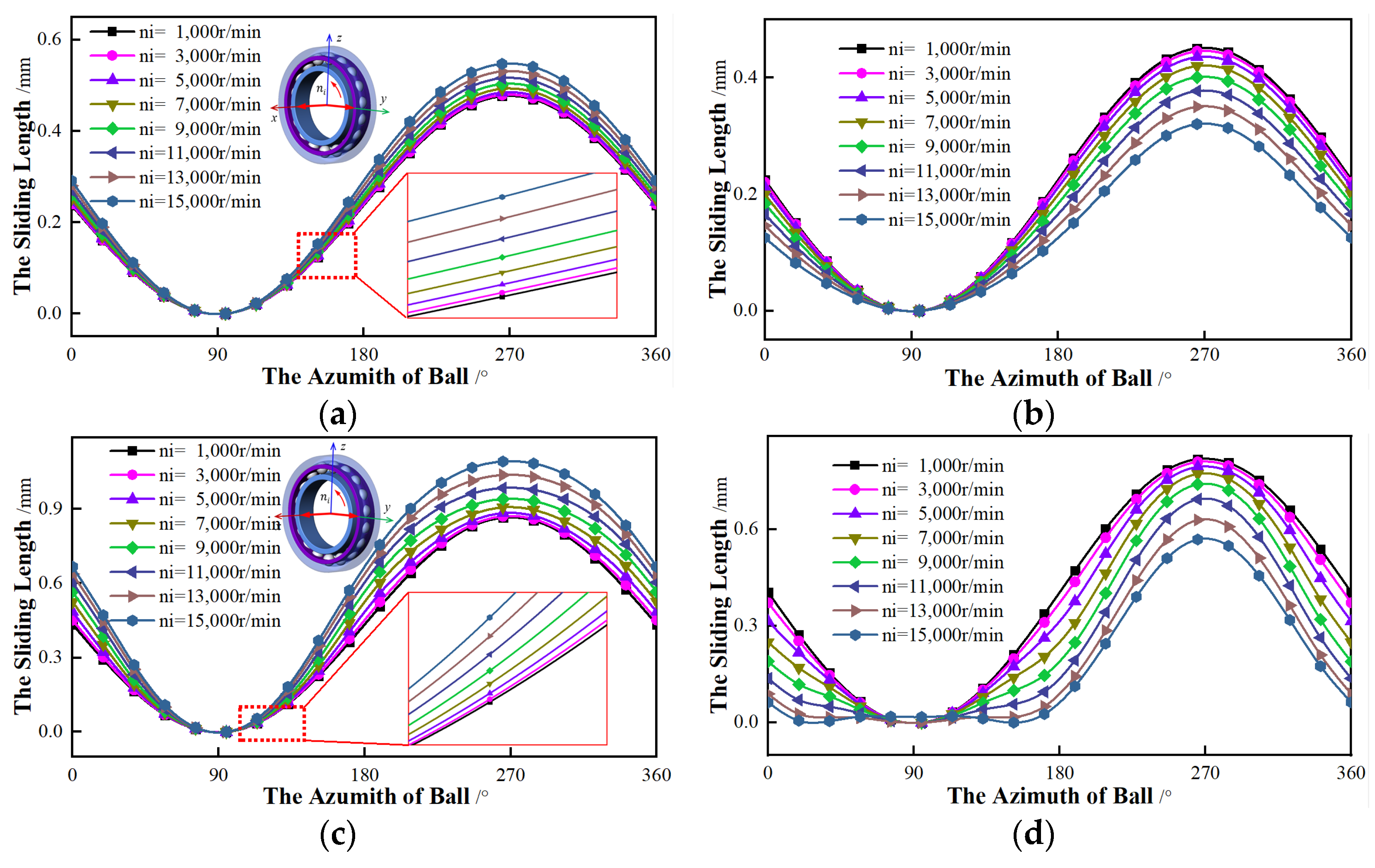
To reveal the influence of rotational speed on sliding length, speed gradually increases. Regardless of the torque (
My =
Mz = 0 N·mm), the axial force (
Fx = 500 N) and the radial force (
Fy = 200 N,
Fz = 0 N) are considered.
Figure 16 shows the relationship between the sliding length and the rotational speed.
Figure 16 shows the curves of the sliding length changing with the rotational speed for the bearing. It can be seen that, as the rotational speed increases, the azimuth angles of
αmin and
αmax remain unchanged. For the inner ring, the higher the speed, the greater the sliding length, and the faster the variation rate of sliding. On the contrary, with the rising rotational speed, the sliding length of the outer ring reduces and the change rate of outer sliding gradually grows. Compared with the outer ring, the inner ring is more sensitive to the speed. As for the bearing with different initial contact angles, the sliding with an initial contact angle of 25° changes more than that of 15°. Besides, for the bearing with an initial contact angle of 25°, the non-sliding area appears near the
αmin.
4.4. Groove Curvature Ratio
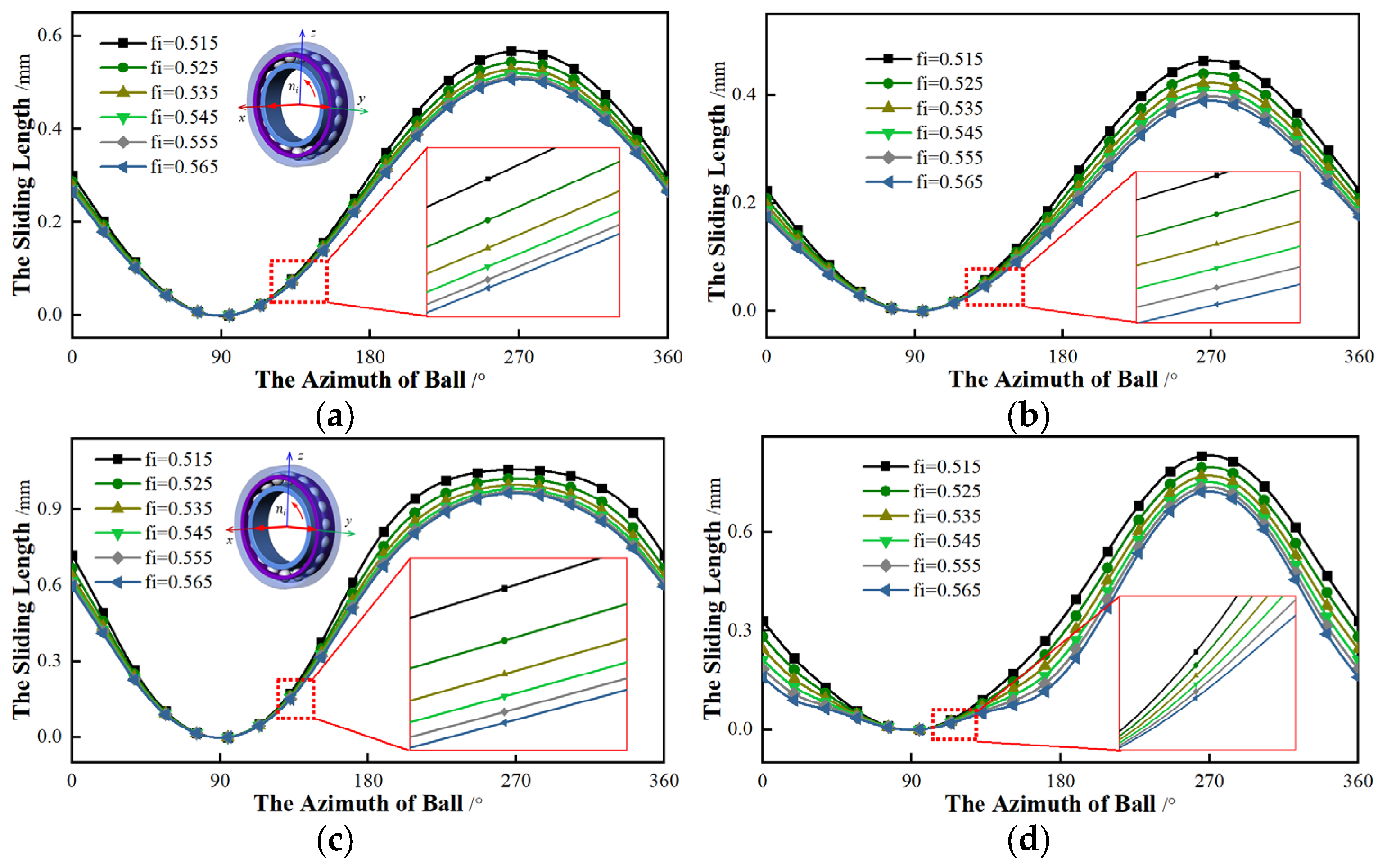
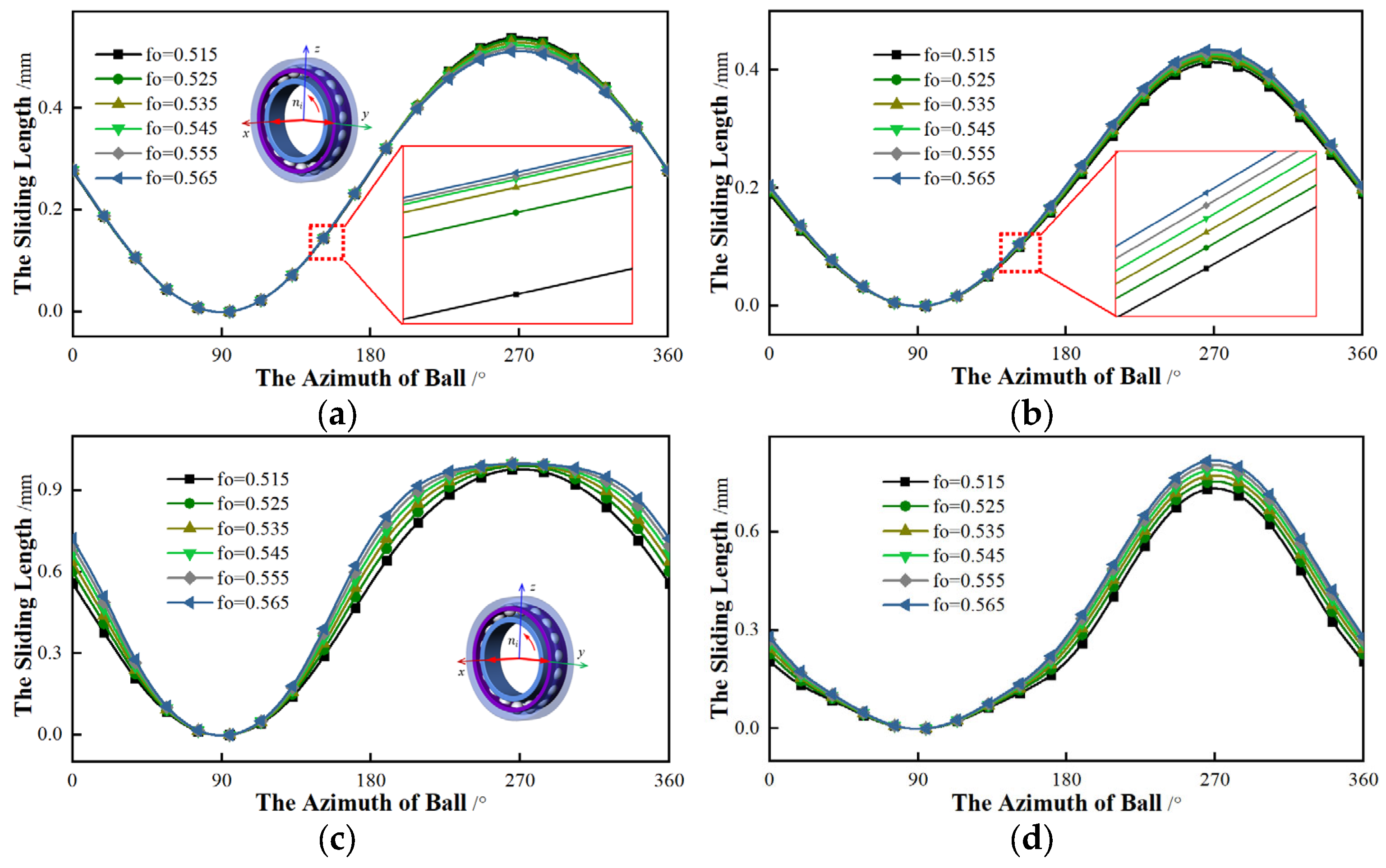
In addition to working conditions, the structural parameters may also affect the sliding. The curvature ratio of the raceway has an important influence on the friction loss. Ignoring the torque (My = Mz = 0 N·mm), a constant combined force (Fx = 500 N, Fy = 200 N, Fz = 0 N) and constant speed (ni = 10,000 r/min) are applied to the bearings. The effects of the curvature ratio of the raceway on the sliding are investigated.
Firstly, the influence of the curvature ratio of the inner raceway on the sliding is considered. The curvature ratio of the outer raceway is constant (
fo = 0.535), while the ratio of the inner (
fi) gradually increases from 0.515 to 0.565. The relationship between the ratio of the inner and the sliding lengths is shown in
Figure 17.
By observing
Figure 17, as the curvature ratio of the inner raceway increases, the azimuths of
αmin and
αmax are constant and the sliding length of rings gradually decreases. However, once the ratio reaches a certain value, the sliding changes will be not obvious. The initial contact angle of the bearing is different, and the influence of the ratio on the sliding is different. The sliding length of a bearing with an initial contact angle of 15° is smaller than that of 25°.
Then the relationship between the curvature ratio of the outer raceway and the sliding is analyzed. Keeping the ratio of the inner constant (
fi = 0.535), the outer ratio (
fo) gradually increases. The influence of the outer ratio on the sliding is presented in
Figure 18. The outer ratio has a weak effect on the sliding length, but the overall trend gradually increases. When the outer ratio exceeds a certain value and continues to increase, the sliding length is almost constant. For bearings with different initial contact angles, the effects of the outer ratio on the sliding are disparate. For the bearing with an initial contact angle of 15°, the effect of the outer ratio on sliding is not distinct. However, the outer ratio has a significant impact on the sliding for the bearing with 25°. As the outer ratio increases, not only the sliding length but also the variation rate of the sliding gradually grows.
To summarize, compared with the curvature ratio of the outer raceway, the sliding is more sensitive to the inner ratio. In addition, the larger the inner ratio, the smaller the sliding length. The influence of the outer ratio on the sliding is just the opposite; with an increasing outer ratio, the sliding gradually decreases.
