Article

Flow Mechanisms and Lubrication Performance of Water-Lubricated Thrust Bearings with Herringbone Grooves

1
School of Mechanical Engineering, Anhui Polytechnic University, Wuhu 241000, China
2
State Key Laboratory of Engines, Tianjin University, Tianjin 300072, China
3
Anhui Huadong Polytechnic Institute, Wuhu 241000, China
4
Institute of Plasma Physics, Chinese Academy of Sciences, Hefei 230031, China
*
Author to whom correspondence should be addressed.
Lubricants 2022, 10(8), 182; https://doi.org/10.3390/lubricants10080182
Submission received: 27 June 2022 / Revised: 24 July 2022 / Accepted: 5 August 2022 / Published: 10 August 2022
(This article belongs to the Special Issue Advances in Bearing Lubrication and Thermal Sciences)

Abstract

:
Due to their excellent stability and zero leakage capability, thrust bearings with herringbone spiral grooves are frequently used in transmission mechanisms. However, the lubrication mechanism of thrust bearings has not been clearly understood and explained, preventing the optimization of the bearing performance. Thus, this paper is devoted to solving this problem by building a three-dimensional finite element flow model. In this model, the change in viscosity temperature is considered using Roelands equation, and the turbulence and cavitation are taken into consideration. Using the established model, the influence of parameters such as spiral angle, groove width ratio, and rotational speed on the cavitation area of the thrust bearing are analyzed. The pressure contour and speed distribution are obtained inside the clearance, as well as the volume fraction of the gas phase at the end face. Finally, according to the analysis results, the optimum structural parameter for the herringbone spiral groove structure is proposed, which enables higher bearing stability and provides a reference for engineering practice.

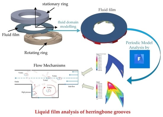
Graphical Abstract

1. Introduction

Herringbone groove thrust bearings (HGTBs) have broad application prospects in hydraulic machinery, machine tool spindles, and other industrial fields [1,2,3], due to the advantages of good stability, high stiffness, and zero leakage. In the bearing, oil and air are commonly used as lubricative mediums. However, the gas-lubricated HGTB has low stiffness, and the oil-lubricated HGTB has a rapid temperature rise. On the opposite, the water-lubricated [4,5] HGTB has excellent dynamic stability and low frictional power consumption. Therefore, water-lubricated HGTBs are more suitable as spindle supports for ultra-precision machine tools under high speeds [6,7,8]. Cavitation, however, commonly occurs in water lubrication, reducing bearing performance and service life. It is valuable for establishing a three-dimensional water-lubricated flow field model considering the cavitation effect, which is used to explore the influence of structural changes on the bearing performance.
In recent years, more and more scholars [9,10] have achieved bearing resistance reduction, and the bearing stability was improved. In some research, it was shown that changes in the lubricating properties of bearings were closely related to the design of the surface texture [11,12,13] (distribution, shape, and size). Guenat [14,15] used the experiment to study the effect of the herringbone groove geometry on lubrication performance deeply. Wang [16] developed a thermo-hydrodynamic model of a combined bearing, and the effect of the groove structure on the bearing characteristics was investigated. If the bearing worked at high speed, the cavitation inception number of water is much higher. Thus, cavitation effects cannot be ignored. Some researchers treat cavitation lubricants as gas–liquid mixed fluids. According to the different calculation methods of the gas volume fraction, the cavitation models in the mixed fluid model can be divided into three types: (1) Model based on the R-P equation [17,18]; (2) Equation model based on gas solubility and surface tension of bubbles [19,20]; (3) Model of the Transport Equation based on Gas Volume Fraction [21,22]. Moreover, some researchers used CFD to analyze the cavitation. In this theory, the journal bearings were investigated numerically in three dimensions by using FLUENT software [23], and the viscosity changes have a significant impact on the pressure distribution, cavity volume, and load-bearing capacity. Furthermore, based on the multi-phase flow cavitation model and the dynamic mesh technology, the cavitation characteristics of the liquid film in the dynamic pressure mechanical seal gap were investigated [24]. Meanwhile, Xu et al. [25] determined the optimal mass transfer coefficient in the Lee phase transition mass transfer equation, and the influence of groove structure parameters on the vaporization characteristics was studied.
In the above literature summary, the herringbone groove structure has been widely used and studied in thrust bearing design. However, the effects of temperature change and cavitation on lubrication states have rarely been studied. In this paper, CFD is used for modeling and analysis. The cavitation effects of the herringbone groove under changes in viscosity and temperature are studied, and its sealing performance and load-bearing performance are analyzed. The lubrication mechanism of the herringbone groove seal is explored, and the influence of the groove structure on the cavitation effect is summarized.

2. Governing Equations

2.1. Conservation Equations

Fluid domains are analyzed using CFD methods, and the relative equations can be found as following.
The mass conservation equation is expressed by Equation (1):
ρ t + ( ρ υ ) = 0
where, ρ represents the fluid density, ρ v is the gravitational body force, and t is the time.
The momentum equation is presented as Equation (2):
ρ d υ d t = p + τ
where, v is the fluid velocity vector, p represents the static pressure, and τ is the stress. The energy equation is given in Equation (3):
( ρ E ) t + [ u ( ρ E + p ) ] = [ k eff T j h j J j + ( τ eff u ) ] + S h
where, E represents the total energy of the fluid, h j is the enthalpy of component j, k eff is the effective heat transfer coefficient, k eff = k + k t , k t denotes the turbulent heat transfer coefficient, J is the diffusion flux of component j, and S h represents the volumetric heat source term.

2.2. Cavitation Equations

The cavitation phenomenon easily appears in the high-speed rotation of the water film. When the temperature changes drastically, the water rises to the boiling point, the originally small bubbles rapidly expand and escape from the surface of the liquid. In this study, the phase change process is mainly controlled by temperature. The volume of fluid (VOF) model is chosen for the tracing of the gas–liquid interface.
The interphase interface is tracked by solving the continuity equation. This equation is solved by using the volume fraction of one (or more) phases. For the q t h phase, this equation has the following form:
1 ρ q [ t ( α q ρ q ) + ( α q ρ q v q ) = S α q + p = 1 n ( m ˙ p q m ˙ q p ) ]
In Equation (4), α v is the phase q volume fraction, ρ q is the phase q density, m ˙ q p is the mass transfer from phase q to phase p, and m ˙ q p is the mass transfer from phase p to phase q. The source term on the right-hand side of Equation (4) (p) is zero.
Among various cavitation models, the Lee model is relatively mature and matches the VOF model well. Therefore, this study adopted the Lee model as the phase transition model. By simplifying Equation (4), the transport equation of the bubble phase is obtained.
t ( α υ ρ υ ) + ( α υ ρ υ υ ) = R e R c
In Equation (5), Re and Rc represent the evaporation and condensation terms in the phase transition process, respectively. They are respectively determined by using the gas and liquid phase medium temperatures, the saturation vaporization temperature is considered, and the relevant equations are as follows:
T l > T sat ,   R e = coeff × α ρ l ( T l T sat   ) T sat   T v < T sat ,   R c = coeff × ( 1 α ) ρ v ( T sat T v ) T sat
where, T represents the local saturation vaporization temperature; coeff is the evaporative condensation coefficient derived from the interfacial concentration under vesicular flow.
coeff = 6 d b η M 2 π R T sat L ( α v ρ v ρ l ρ v )
where, d is the vapor bubble diameter, and η represents called the coefficient of adaptation and characterizes the adsorption of vapor molecules on the surface of the liquid, approximated by 1 under equilibrium conditions. L is the latent heat of vaporization, M is the molar mass, and R is the gas constant.

3. Model Analysis

3.1. Geometric Model

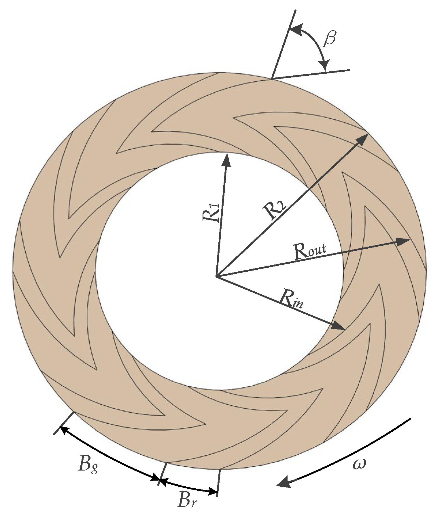
The simplified structure of the herringbone thrust bearing is shown in Figure 1 and Figure 2. Compared with the general single-sided spiral groove structure, the lubricating medium at the inner and outer diameters is pumped into the groove when the bearing is in operation. This structure has excellent lubrication and sealing performance. Its structural expressions in the rθ coordinate system are given by Equations (8) and (9):
R in = R 1 e θ cot β
R out = R 2 e θ cot β
In Equations (8) and (9), R1 is the inner diameter, R2 represents the outer diameter, β is the spiral angle, θ denotes the angle, Rin is the inner spiral, Rout is the outer spiral, Bg is the groove width, Br is the ridge width, B is the groove width ratio, B = Bg/Br, H2 is the water film depth, and H1 is the bearing clearance.

3.2. CFD Model

The calculation model is simplified on the premise of assuring the accuracy of the calculation results and given the following assumptions: the effects of body force and inertial force are ignored, the speed slip is neglected, the effect of surface roughness is ignored.
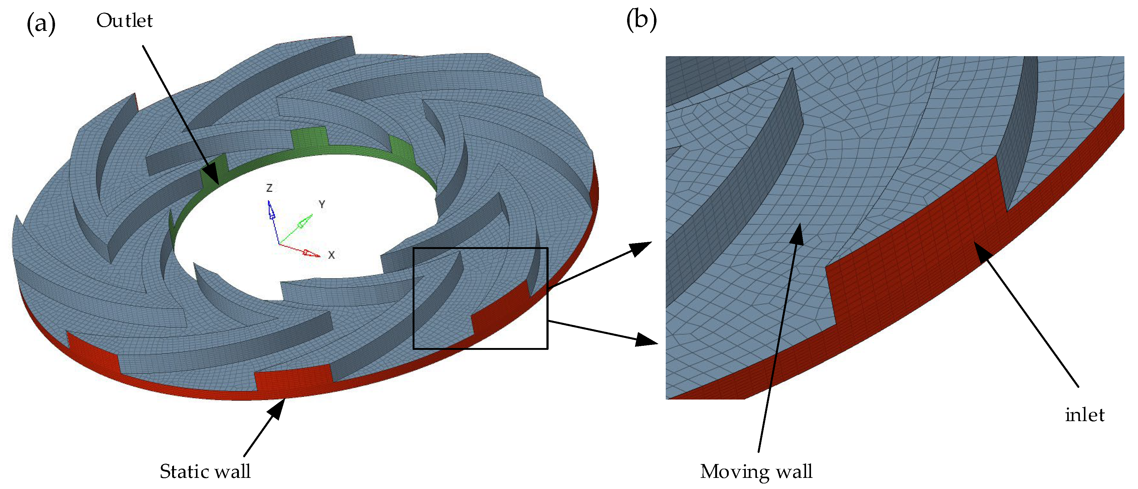
A CFD model is built by considering the above assumptions. Solidworks is used for geometric modeling, and ANSYS is used for the meshing. Finally, the case is solved in Fluent. The film thickness direction is enlarged 100 times for facilitating observation. The grid and boundary conditions for the clearance water film are presented in Figure 3. The three-dimensional geometry of the clearance was discretized with Hexahedral elements, the quality of the grid was assessed by checking the elements’ quality (0.98), aspect ratio (1.1), and skewness (0.04). Then, it is indicating that the grid was of high quality. Due to the existence of fluid viscosity, there will be a boundary layer when the fluid moves in the near-wall region. As shown in Figure 3b, grid refinements are made on both sides of the wall. The inlet and outlet of the three-dimensional model are set as pressure boundaries, the walls in contact with the rotating ring are set as rotating walls, and the others are set as static walls.

3.3. Viscosity–Temperature Relationship

For the high-temperature sealing medium, the change in medium viscosity with temperature must be considered. Roelands equation [26] is as follows:
μ = μ 0 exp [ ε ( 1 T 1 T 0 ) ]
where μ is the dynamic viscosity of water, T is the water temperature, and μ0 is the viscosity at the reference temperature T0.

3.4. Solver Settings

A mixture model was selected and analyzed. Then, the implicit method was adopted. In this study, liquid water was set as the primary phase, and water vapor was set as the secondary phase. The two phases were embedded in the mass transfer mechanism. “Dispersed” was selected as the interface type. The Zwart–Gerber–Belamri model was used in the simulation.
A pressure-based solver was chosen for the numerical simulation. The SIMPLE algorithm was used, which is an algorithm based on the pressure-velocity coupling principle. Then, the default state was used in other settings. A tolerance of 10−3 was set for the residual terms.

3.5. Verification of the Model

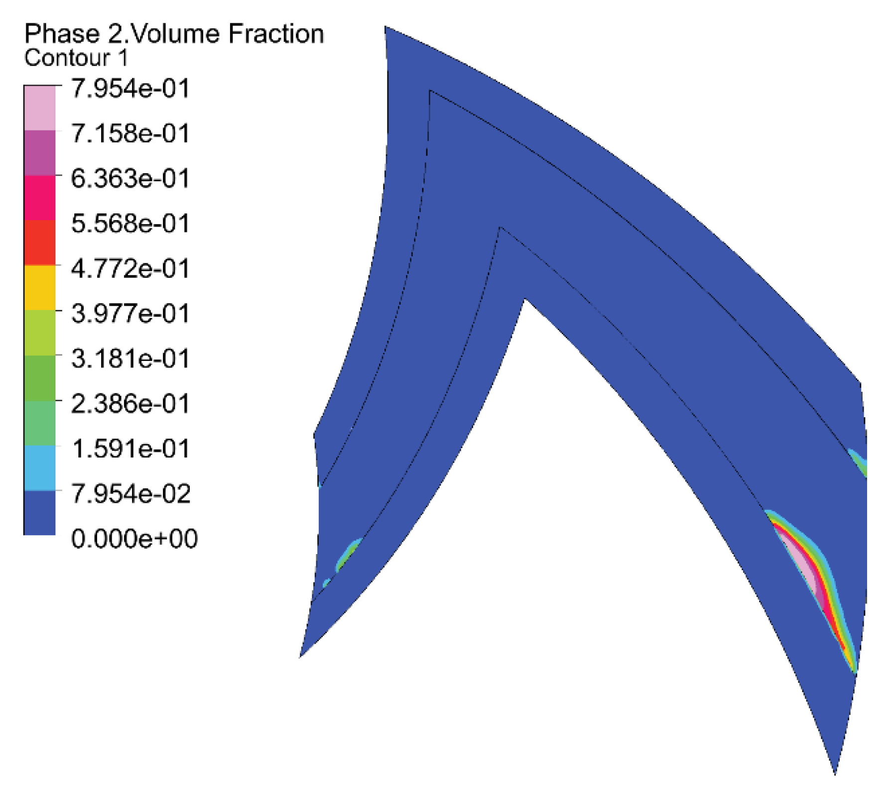
The work in Ref. [27] is similar to that of this paper, and the research method has been proved by experimental tests. Therefore, the results in Ref. [27] can be used to confirm the model established in this paper, and the result is given in Figure 4. It is found that the cavitation position obtained from the model established in this paper is consistent with the result in the literature [27].
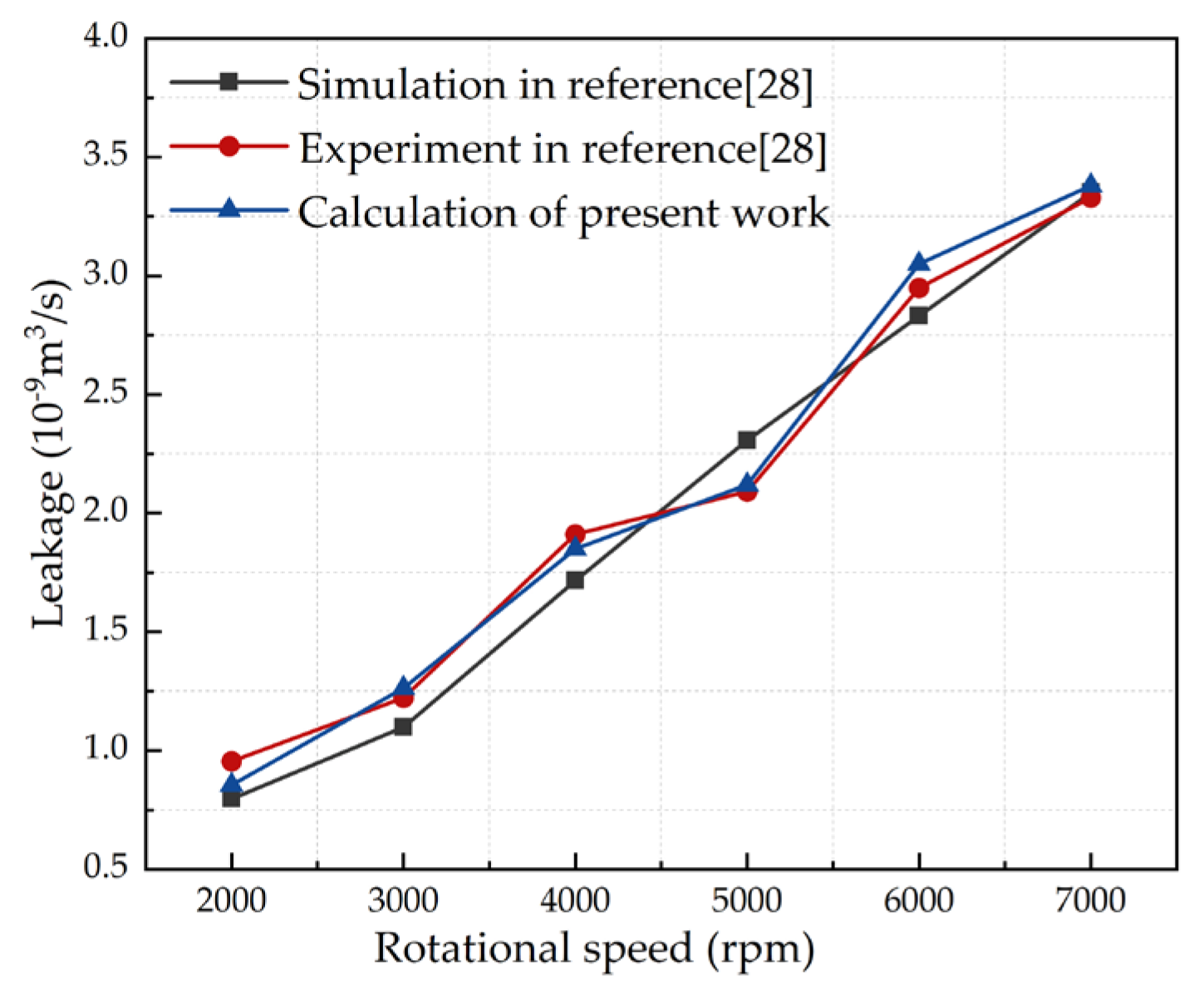
The leakage was obtained experimentally and validated as a quantitative indicator. As shown in Figure 5, the results of current work calculation are analogous with theoretical values and tests in the literature [27]. The relative error between this study and Ref. [27] is less than 5%, which proves the reliability of the proposed model.

4. Results and Discussion

The subsequent simulation solution takes a single cycle model caused by the flow’s periodicity. Then, computer resources are saved, and the accuracy of solution is improved. The geometric and working parameters of the face seal are shown in Table 1.

4.1. Liquid Film Flow Mechanism

The flow, which is inside a micro gap, is difficult to capture. Thus, its flow characteristics cannot be accurately understood. In this paper, a cross-sectional approach was chosen to demonstrate micro gap flow. The method is as follows: the actual film thickness is used in the simulations, but it is scaled up in the direction of the film thickness when the detailed flow is charactered.
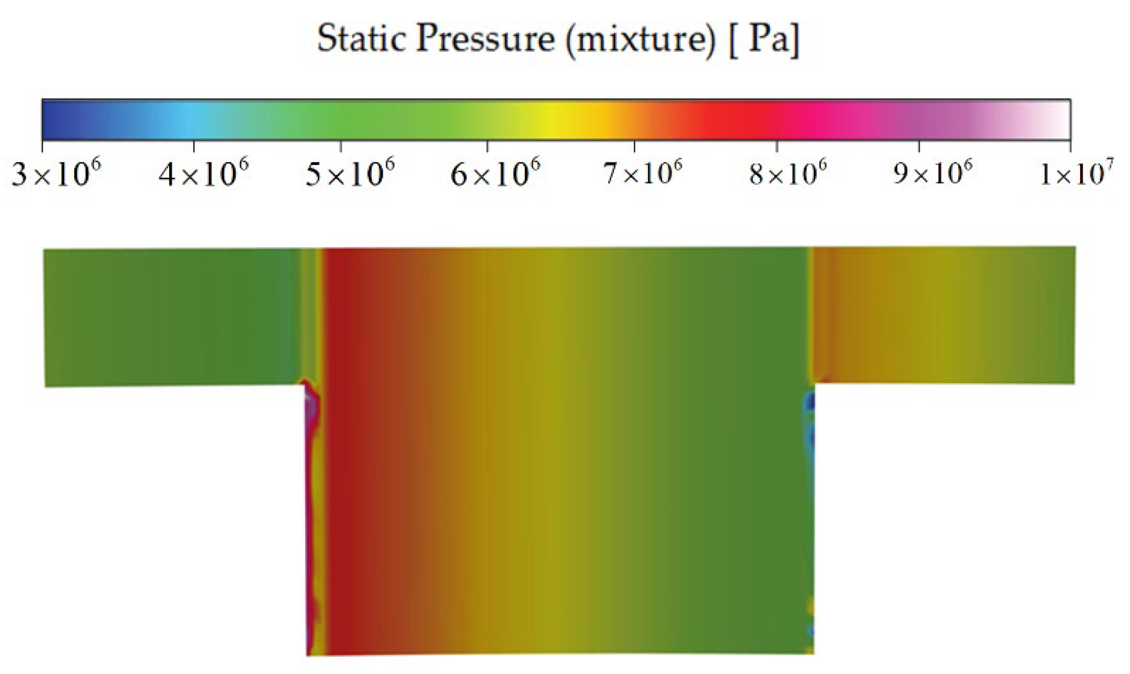
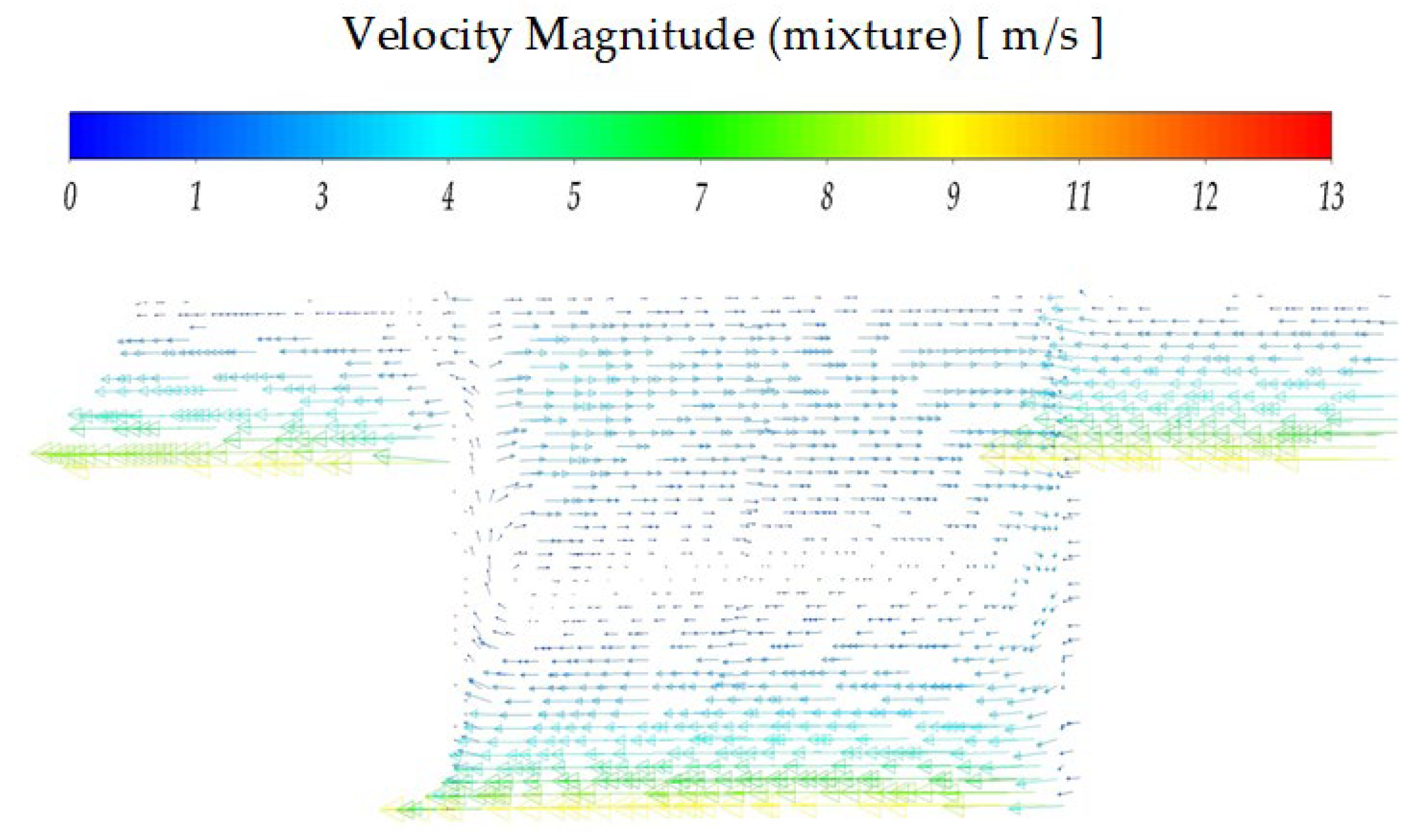
When HGTB is working, the lubricating medium for groove structure is pumped into the top. Under the obstruction of the ridge, a part of the fluid slows down and increases the pressure, and the other part of the fluid climbs over the ridge. Thus, the most complex area of flow is at the top of the groove. Figure 6 and Figure 7 show the pressure distribution and velocity field distribution on the radius section at the top of the groove, respectively. As shown in Figure 6, the pressure in this section is concentrated at the top of the groove. Because of the extremely small gap size, there is no significant pressure change in the thickness direction of the film. From the results in Figure 7, eddy currents exist in the gap. The fluid is divided into two parts: one part creates eddy currents in the groove, and the other part goes to lubricate the bearing clearance.
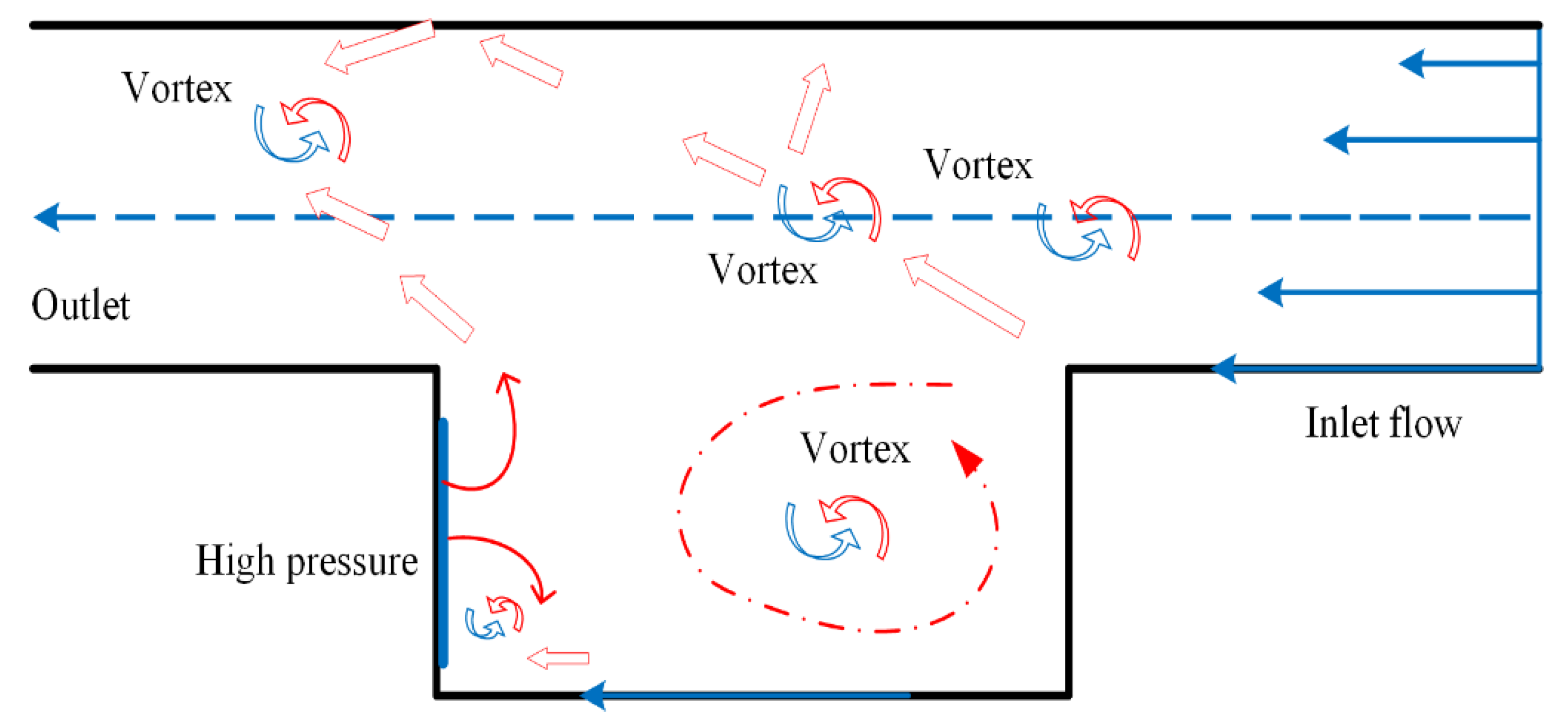
In Figure 8, when the groove surface moves, the fluid in the groove is pushed from one side to the other. Fluid flow characteristics in the micro gap are abundant. The fluid is squeezed at the front face, and a pressure peak is generated. The fluid after the collision is divided into two parts: one forms a vortex in the groove, and the other flows to the bearing gap. The fluid in the clearance acts as a lubricating medium, and the bearing surfaces are pushed apart. Thus, the load-carrying capacity is increasing, and the friction coefficient is reduced [28].

4.2. Influence of Rotational Speed on the Flow Field

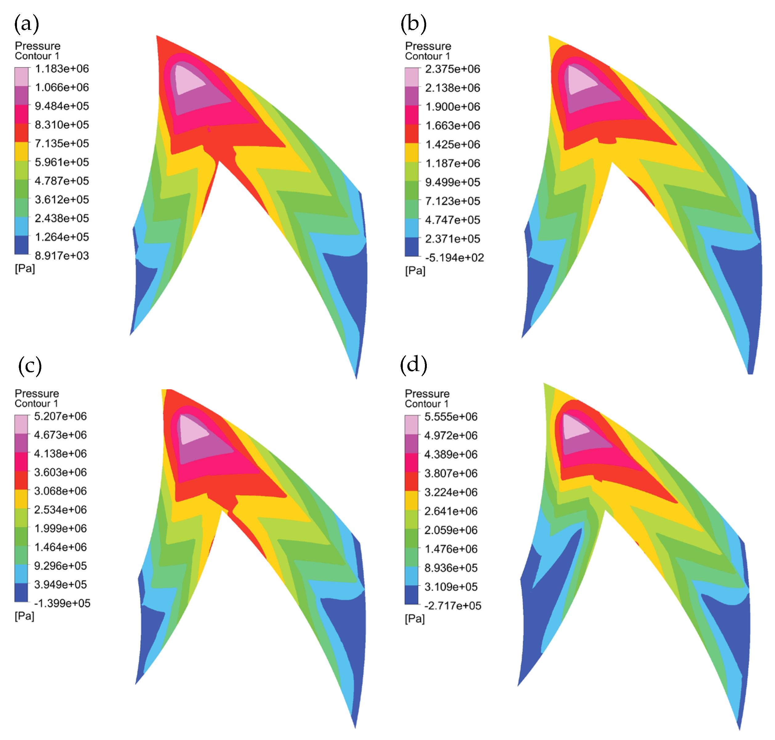
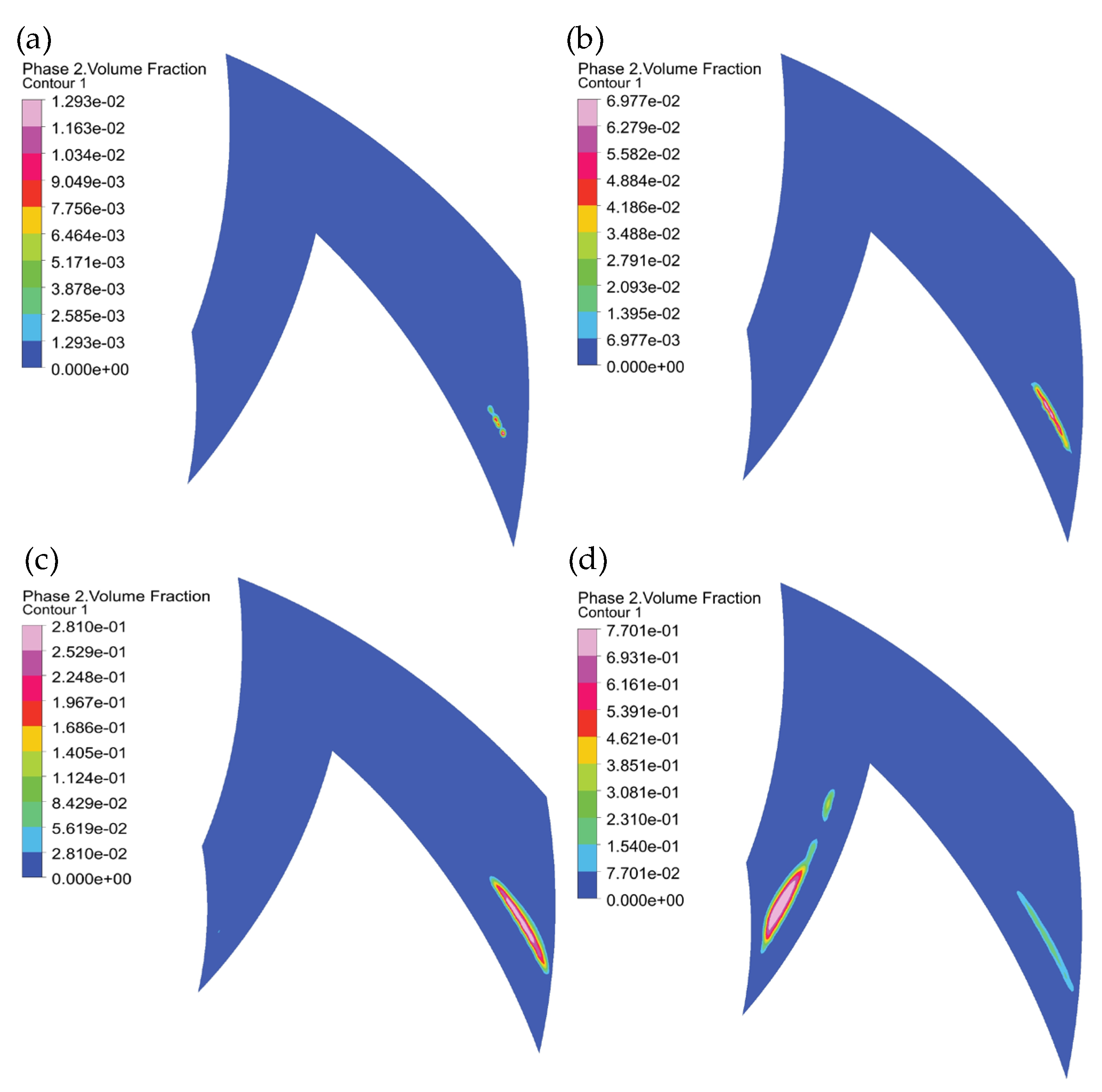
When the speed is changing, and other parameters remain constant. The fluid film pressure distribution can be seen in Figure 9. A high-pressure area appears at the tip of the herringbone groove. Low-pressure areas appear at the groove root of the outer diameter side of the herringbone groove, the groove root, and side wall of the inner diameter side groove. As shown in Figure 10, cavitation takes place at the root of the outer diameter side groove and the side wall of the inner diameter.
As the rotational speed increases, the maximum pressure of the fluid film magnifies, and the pressure distribution law of the fluid film is unchanged. The cavitation area gradually expands with the increasement of the rotational speed, which indicates that the cavitation area is extensible.

4.3. Influence of Structural Parameters on the Flow Field

4.3.1. Spiral Angle

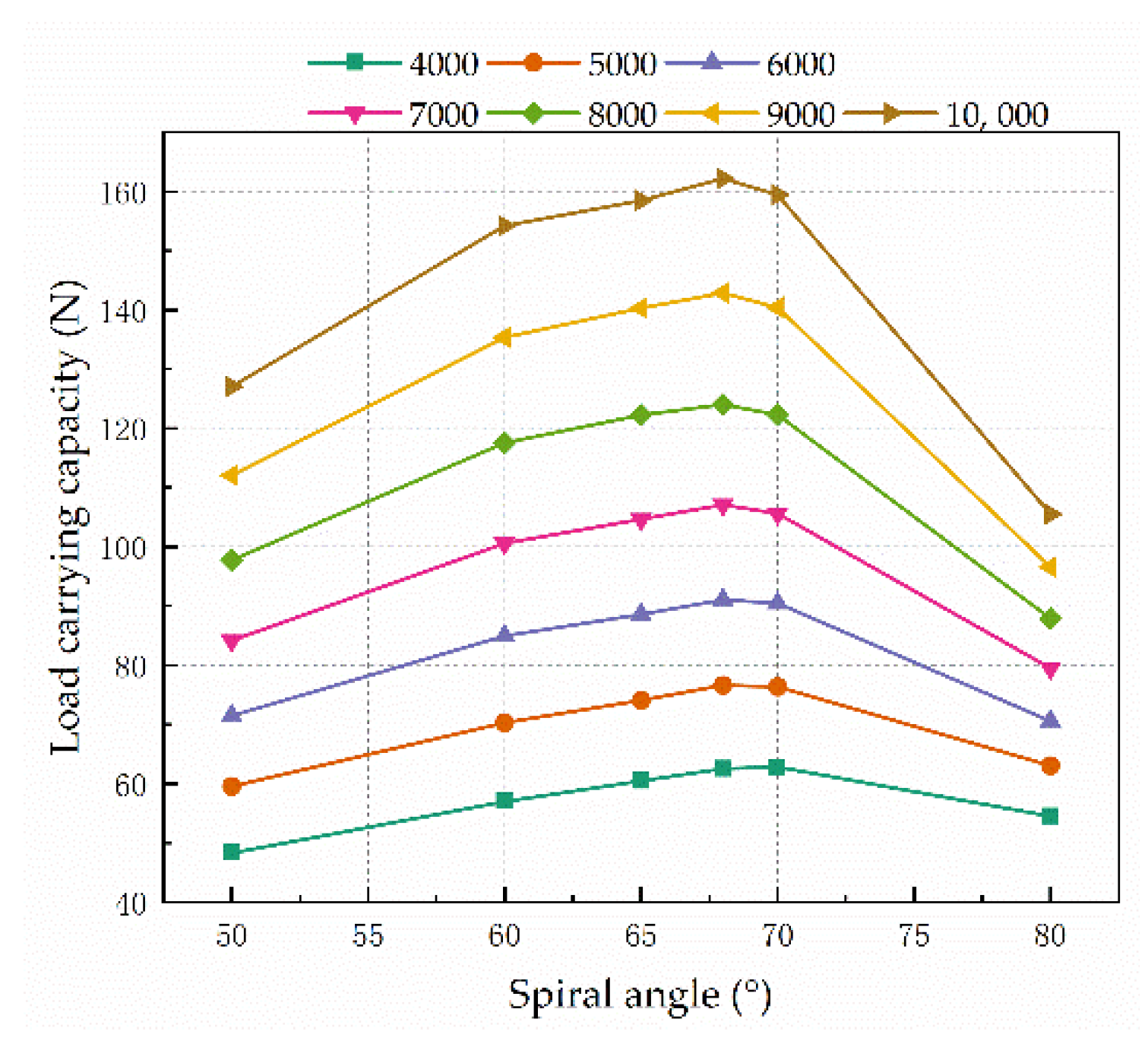
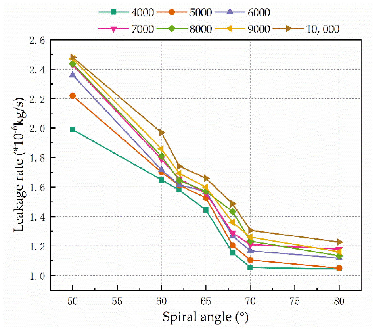
The spiral angle β directly affects the boosting effect of the thrust bearing. In the Figure 11 and Figure 12, the effect of the spiral angle on the bearing’s load-carrying capacity and leakage rate was investigated. The load capacity appears to increase with spiral angle from 50° to 70°. Then, it decreases as the spiral angle increases. When the spiral angle is about 68°, the bearing capacity reaches the maximum value. When the spiral angle is 0° or 90°, the dynamic pressure effect and step effect are greatly reduced, and the bearing capacity is almost lost. Thus, the leakage exhibits the downtrend.

4.3.2. Groove Width Ratio

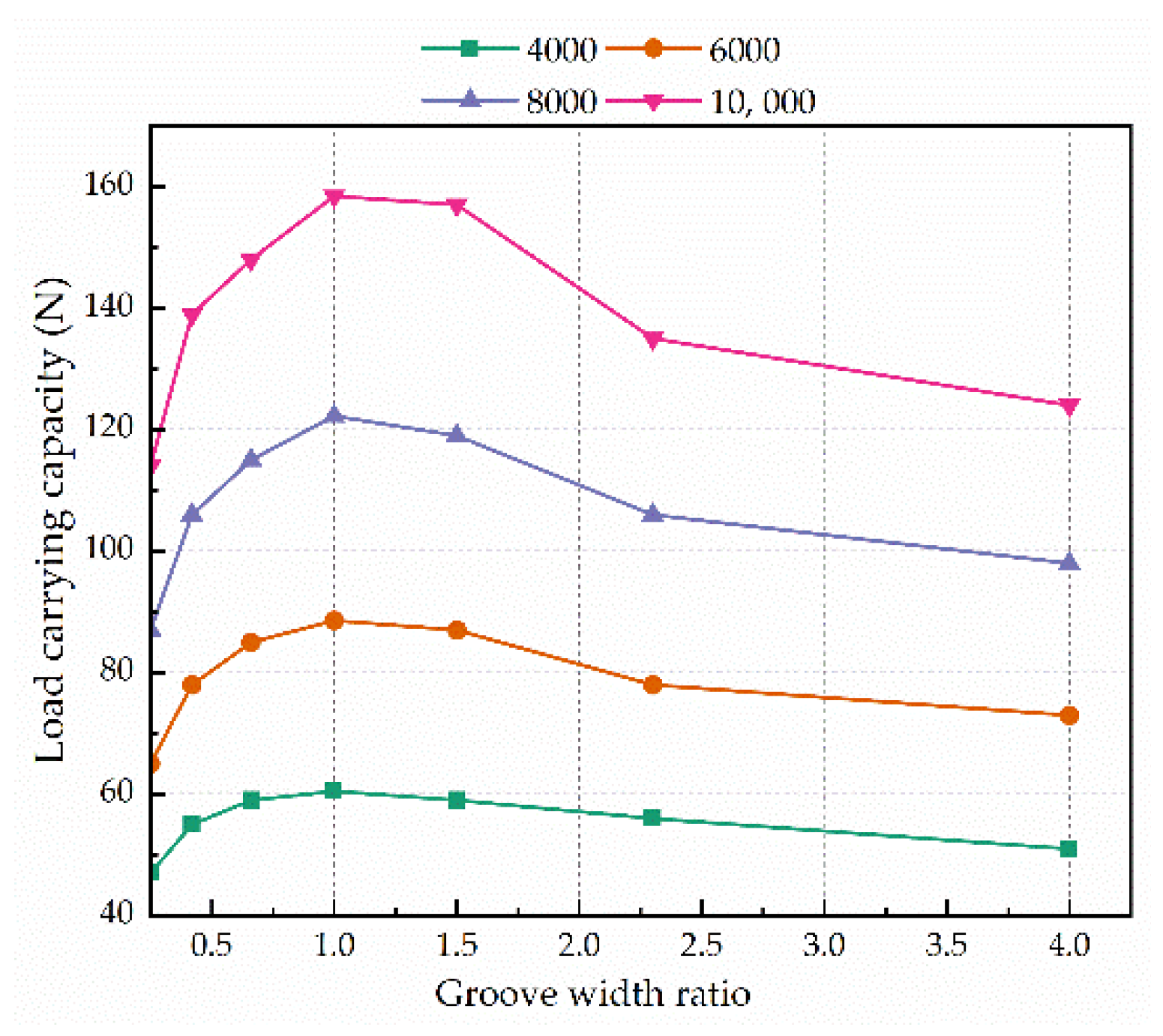
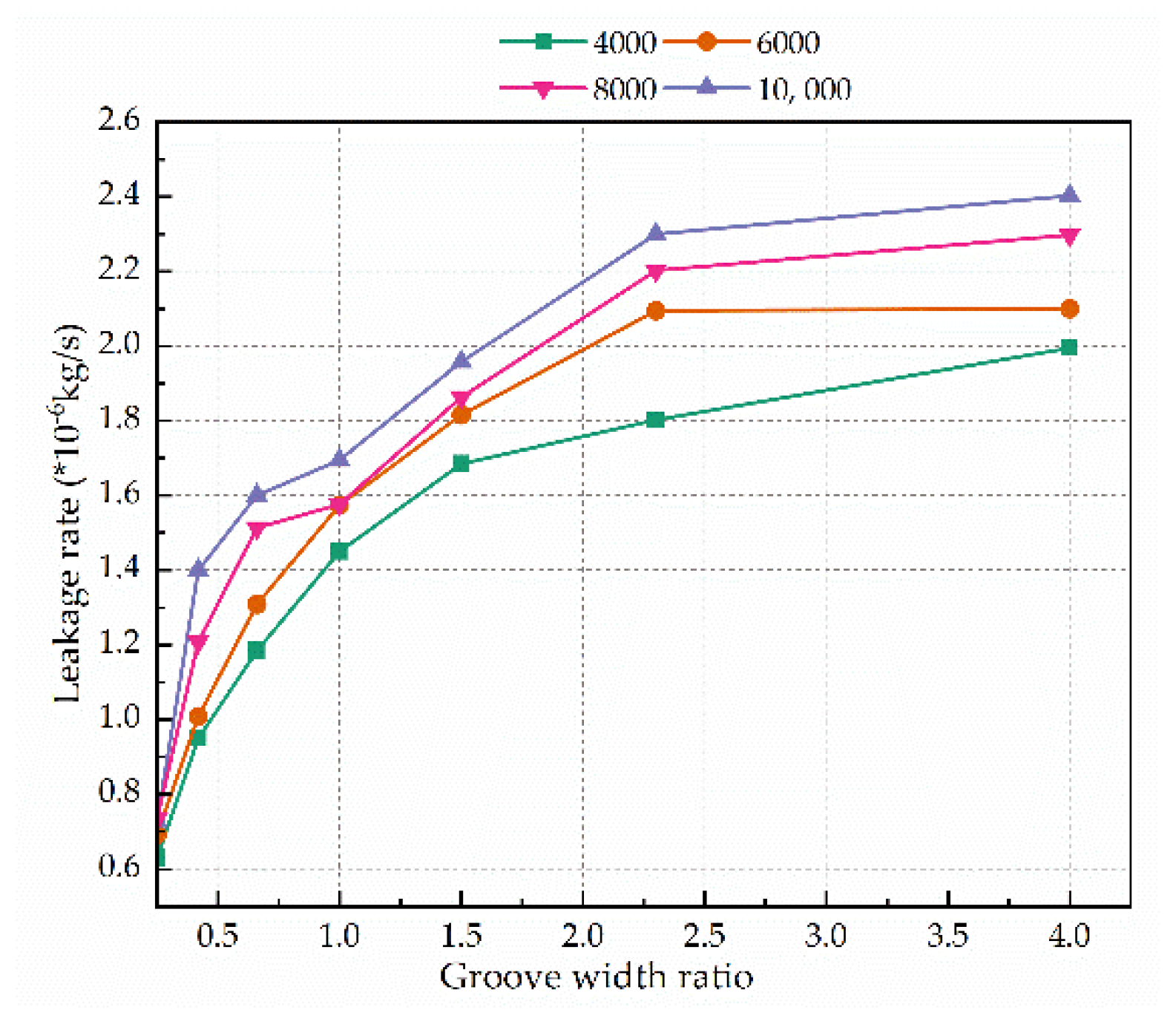
From Figure 13, as the groove width ratio increases, the axial load capacity of the thrust bearing gradually increases. When the groove width ratio is about 1, the bearing capacity reaches the maximum value, and then gradually decreases. If the groove width ratio is equal to 0 or infinite, the bearing end face becomes flat, and the dynamic pressure effect and step effect cannot be found. Therefore, there is a suitable groove width ratio to maximize the bearing capacity. As seen in Figure 14, when the groove width ratio increases, the leakage also increases and tends toward a stable value. The magnified groove width ratio corresponds indirectly increases the clearance of the bearing, and the leakage is also increasing.

5. Conclusions

In this study, a finite element flow field model is established to understand and explain the flow mechanisms of HGTBs. The influence of structural parameters on the bearing performance was investigated. In this model, viscous temperature changes, turbulence, and cavitation are considered. The main conclusions are summarized as follows:
(1) Water is pumped into the spiral groove from both ends by vicious and differential pressure forces. The lubricating medium is converged at the top of the herringbone groove. Then, one part of the fluid goes over the ridge, and the other part forms vortices in the groove. The lubrication performance of the thrust bearing is affected by the dynamic pressure and the step.
(2) The cavitation is concentrated at the root of the outer diameter side of the herringbone groove and the inner diameter wall. The cavitated area is extended by the increasing rotational speed. There is an optimum value for the groove width ratio B and the helix angle β, which can improve the bearing performance.
(3) Optimum values for the geometrical parameters of the thrust bearing have been determined using the load-carrying capacity and leakage. When the bearing clearance is 10 μm, the groove width ratio is taken as 1, and the spiral angle β can be selected from 65° to 70°.

Author Contributions

Conceptualization, H.R.; methodology, H.R.; software, H.R.; validation, J.W. and S.Y.; formal analysis, F.W.; investigation, F.W.; resources, P.D. and J.W.; data curation, P.D. and S.Y.; writing—original draft preparation, H.R.; writing—review and editing, F.W. and J.W.; visualization, P.D. and G.Z.; supervision, X.Y. and S.Y.; project administration, X.Y. All authors have read and agreed to the published version of the manuscript.

Funding

The work described in this paper was supported by the National Natural Science Foundation of China (No. 51905001), the Science and Technology of Wuhu (No. 2021yf09), and the Anhui Province Science and Technology Major Project (202103a05020033), Research Project of Anhui Polytechnic University (No. Xjky2022012).

Institutional Review Board Statement

Not applicable.

Informed Consent Statement

Not applicable.

Data Availability Statement

The data that support the findings of this study are available from the author, H.R., upon reasonable request.

Conflicts of Interest

The authors declare no conflict of interest.

References

  1. Wang, C.-C.; Lin, J.-T. Numerical study of hydrodynamic herringbone-grooved journal bearings combined with thrust bearings considering thermal effects. J. Mech. 2022, 38, 13–21. [Google Scholar] [CrossRef]
  2. Yu, Y.; Pu, G.; Jiang, T.; Jiang, K. Discontinuous grooves in thrust air bearings designed with CAPSO algorithm. Int. J. Mech. Sci. 2020, 165, 105197. [Google Scholar] [CrossRef]
  3. Wagner, P.H.; Van Herle, J.; Schiffmann, J. Theoretical and Experimental Investigation of a Small-Scale, High-Speed, and Oil-Free Radial Anode Off-Gas Recirculation Fan for Solid Oxide Fuel Cell Systems. J. Eng. Gas Turbines Power 2020, 142, 041023. [Google Scholar] [CrossRef]
  4. Qiao, J.; Zhou, G.; Pu, W.; Li, R.; He, M. Coupling analysis of turbulent and mixed lubrication of water-lubricated rubber bearings. Tribol. Int. 2022, 172, 107644. [Google Scholar] [CrossRef]
  5. Liu, Q.; Ouyang, W.; Cheng, Q.; Li, J.; Cheng, Q.; Li, R. Influences of bidirectional shaft inclination on lubrication and dynamic characteristics of the water-lubricated stern bearing. Mech. Syst. Signal Process. 2022, 169, 108623. [Google Scholar] [CrossRef]
  6. Lin, X.; Wang, S.; Jiang, S.; Zhang, S. Thermohydrodynamic Model of Cavitating Flow and Dynamic Characteristic Calculation for High-Speed Water-Lubricated Pump-Out Spiral Groove Bearing. Tribol. Trans. 2020, 63, 736–755. [Google Scholar] [CrossRef]
  7. Zhang, S.; Jiang, S.; Lin, X. Static and dynamic characteristics of high-speed water-lubricated spiral-groove thrust bearing considering cavitating and centrifugal effects. Tribol. Int. 2020, 145, 106159. [Google Scholar] [CrossRef]
  8. Wang, D.; Mo, J.; Wang, Z.; Chen, G.; Ouyang, H.; Zhou, Z. Numerical study of friction-induced vibration and noise on groove-textured surface. Tribol. Int. 2013, 64, 1–7. [Google Scholar] [CrossRef]
  9. Feng, H.; Jiang, S.; Shang-Guan, Y. Three-dimensional computational fluid dynamic analysis of high-speed water-lubricated hydrodynamic journal bearing with groove texture considering turbulence. Proc. Inst. Mech. Eng. Part J. J. Eng. Tribol. 2021, 235, 2272–2286. [Google Scholar] [CrossRef]
  10. Guo, Z.; Xie, X.; Yuan, C.; Bai, X. Study on influence of micro convex textures on tribological performances of UHMWPE material under the water-lubricated conditions. Wear 2019, 426–427, 1327–1335. [Google Scholar] [CrossRef]
  11. Chang, T.; Guo, Z.; Yuan, C. Study on influence of Koch snowflake surface texture on tribological performance for marine water-lubricated bearings. Tribol. Int. 2019, 129, 29–37. [Google Scholar] [CrossRef]
  12. Feng, H.; Peng, L. Numerical analysis of water-lubricated thrust bearing with groove texture considering turbulence and cavitation. Ind. Lubr. Tribol. 2018, 70, 1127–1136. [Google Scholar] [CrossRef]
  13. Xie, Z.; Shen, N.; Ge, J.; Zhu, W.; Song, P.; Liu, H.; Hao, L.; Tian, W. Analysis of the flow noises of the nuclear main pump caused by the high temperature liquid Sodium in the two-circuit main loop liquid Sodium pump system. Ann. Nucl. Energy 2020, 145, 107550. [Google Scholar] [CrossRef]
  14. Guenat, E.; Schiffmann, J. Dynamic force coefficients identification on air-lubricated herringbone grooved journal bearing. Mech. Syst. Signal Process. 2020, 136, 106498. [Google Scholar] [CrossRef]
  15. Guenat, E.; Schiffmann, J. Performance potential of gas foil thrust bearings enhanced with spiral grooves. Tribol. Int. 2019, 131, 438–445. [Google Scholar] [CrossRef]
  16. Wang, L.; Han, Y.; Tang, D.; Cai, J. Numerical and Experimental Investigations on the Wear Behavior of Water-Lubricated Bearings with Different Materials. Ind. Lubr. Tribol. 2022, 74, 134–143. [Google Scholar] [CrossRef]
  17. Song, Y.; Gu, C.-W. Development and Validation of a Three-Dimensional Computational Fluid Dynamics Analysis for Journal Bearings Considering Cavitation and Conjugate Heat Transfer. J. Eng. Gas Turbines Power 2015, 137, 122502. [Google Scholar] [CrossRef]
  18. Wang, Y.; Yin, Z.; Jiang, D.; Gao, G.; Zhang, X. Study of the lubrication performance of water-lubricated journal bearings with CFD and FSI method. Ind. Lubr. Tribol. 2016, 68, 341–348. [Google Scholar] [CrossRef]
  19. Grando, F.P.; Priest, M.; Prata, A.T. A two-phase flow approach to cavitation modelling in journal bearings. Tribol. Lett. 2006, 21, 233–244. [Google Scholar] [CrossRef]
  20. Wang, L.; Zeng, Q.; Lu, C.; Liang, P. A numerical analysis and experimental investigation of three oil grooves sleeve bearing performance. Ind. Lubr. Tribol. 2019, 71, 181–187. [Google Scholar] [CrossRef]
  21. Zhang, X.; Yin, Z.; Gao, G.; Li, Z. Determination of stiffness coefficients of hydrodynamic water-lubricated plain journal bearings. Tribol. Int. 2015, 85, 37–47. [Google Scholar] [CrossRef]
  22. Chen, Y.; Sun, Y.; He, Q.; Feng, J. Elastohydrodynamic Behavior Analysis of Journal Bearing Using Fluid–Structure Interaction Considering Cavitation. Arab. J. Sci. Eng. 2019, 44, 1305–1320. [Google Scholar] [CrossRef]
  23. Taghipour, Y.; Akbarzadeh, P.; Moradgholi, F.; Yazdi, M.E. Numerical study of the cavitation effect on plain bearings in constant and variable viscosity states. Meccanica 2021, 56, 2507–2516. [Google Scholar] [CrossRef]
  24. Chen, H.; Wu, Q.; Xu, C.; Zuo, M. Research on Cavitation Regions of Upstream Pumping Mechanical Seal Based on Dynamic Mesh Technique. Adv. Mech. Eng. 2014, 6, 821058. [Google Scholar] [CrossRef] [Green Version]
  25. Xu, X.D.; Ma, C.B.; Sun, J.J.; Zhang, Y.Y.; Yu, Q.P. Influence and optimization of groove structure parameters on vaporization characteristics of liquid film mechanical seals based on optimal mass transfer coefficient. Chem. J. 2022, 73, 1147–1156. [Google Scholar]
  26. Bair, S. A Routine High-Pressure Viscometer for Accurate Measurements to 1 GPa. Tribol. Trans. 2004, 47, 356–360. [Google Scholar] [CrossRef]
  27. Yang, D.D. Steady Character Research and Software Development of Liquid Film Seal with Herringbone Grooves. Master’s Thesis, China University of Petroleum, Beijing, China, 2016. Available online: https://kns.cnki.net/KCMS/detail/detail.aspx?dbname=CMFD201801&filename=1018814320.nh (accessed on 8 July 2022).
  28. Xie, Z.; Zhang, Y.; Zhou, J.; Zhu, W. Theoretical and experimental research on the micro interface lubrication regime of water lubricated bearing. Mech. Syst. Signal Process. 2021, 151, 107422. [Google Scholar] [CrossRef]
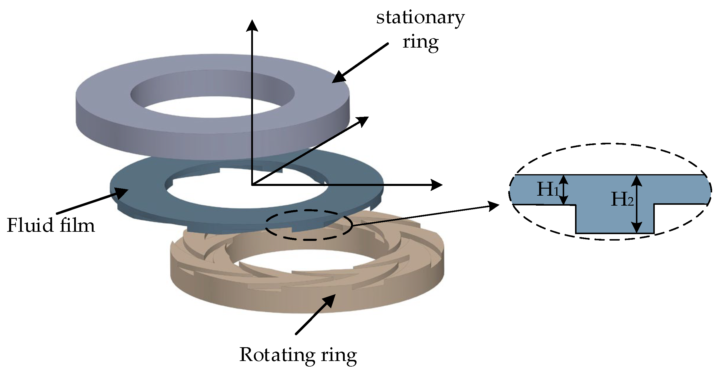
Figure 1. Bearing structures.
Lubricants 10 00182 g001
Figure 2. Surface texture model.
Lubricants 10 00182 g002
Figure 3. Grid and boundary conditions for the water film. (a) grid of the water film; (b) detailed information on the grid.
Lubricants 10 00182 g003
Figure 4. Vapor phase volume fraction distribution.
Lubricants 10 00182 g004
Figure 5. Verification of the model by using reference [27,28].
Lubricants 10 00182 g005
Figure 6. Pressure distribution of cross-section in the gap.
Lubricants 10 00182 g006
Figure 7. Velocity distribution of cross-section in the gap.
Lubricants 10 00182 g007
Figure 8. Schematic representation of the fluid motion within bearing clearance.
Lubricants 10 00182 g008
Figure 9. Liquid film pressure distribution. (a) 2000 rpm; (b) 4000 rpm; (c) 6000 rpm; (d) 8000 rpm.
Lubricants 10 00182 g009
Figure 10. Liquid film gas phase volume fraction distribution. (a) 2000 rpm; (b) 4000 rpm; (c) 6000 rpm; (d) 8000 rpm.
Lubricants 10 00182 g010
Figure 11. Effect of the spiral angle on the load-carrying capacity.
Lubricants 10 00182 g011
Figure 12. Effect of the spiral angle on the leakage rate.
Lubricants 10 00182 g012
Figure 13. Effect of the groove width ratio on the load-carrying capacity.
Lubricants 10 00182 g013
Figure 14. Effect of the groove width ratio on the leakage rate.
Lubricants 10 00182 g014
Table 1. Geometric and operating parameters.
ParametersValue
Temperature T   ( K ) 300
Groove number N 18
rotational speed n   ( rpm ) 6000
Spiral groove angle β   ( ° ) 65
Inner radius R 1   ( mm ) 15
Outer radius R 2   ( mm ) 20
Pressure inlet P in   ( MPa ) 0.1
Pressure outlet P out   ( MPa ) 0.2
Water film depth H 2   ( μ m ) 30
Bearing clearance H 1   ( μ m ) 10
Density ρ   ( kg / m 3 ) 998.2
Viscosity μ   ( Pa · s ) 8.49 × 10 4
Publisher’s Note: MDPI stays neutral with regard to jurisdictional claims in published maps and institutional affiliations.