1. Introduction
Lightweight manufacturing in the automotive industry is one of the topics at the forefront of research activities for two main reasons: the reduction of emissions and the positive effect on road safety [
1,
2]. In this regard, ultra-high-strength aluminium alloys are in high demand in the automotive and aerospace industries, where weight savings are critical. The alloys of the 7000 series, which are primarily mixed with zinc and small amounts of magnesium and copper, are hardenable and very resistant. The most popular alloys from this group, 7050 and 7075, are already widely used in aviation and aerospace, e.g., for aircraft wings, and are currently starting to be used in the automotive industry [
3]. On the other hand, tool materials used for high-speed cutting of ultra-high-strength aluminium alloys are subjected to severe conditions that promote premature failure of cutting tools.
The constant evolution of these materials and their applications requires the development of tools that can withstand such severe working conditions while optimizing the performance, durability and costs of cutting and machining processes. These requirements can be achieved through the application of hard coatings. Compared to an unprotected tool, a coated tool exhibits a higher resistance to mechanical and thermal fatigue, a lower coefficient of friction, less interaction between the tool and the machined material, and an improved wear resistance over a wide temperature range. In this respect, the hardest materials known and used in industry are diamond and cubic boron nitride (cBN). Both can be obtained in polycrystalline form (PCD, PcBN) and applied as a coating. While the former is more suitable for machining non-ferrous materials (because carbon reacts chemically with iron), the latter applies to iron-containing alloys [
4].
There are two types of polycrystalline diamond coatings used in the tool industry: those obtained by the High-Pressure High-Temperature method (HPHT), and those applied by Chemical Vapor Deposition (CVD). It should be noted that both types of coatings meet the most stringent requirements for cutting and machining materials for the aeronautical sector. These include high hardness (50–100 GPa), high abrasion resistance, high thermal conductivity (800 W/mK), high temperature resistance, low coefficient of friction (between 0.05 and 0.2), low coefficient of expansion, chemical inertness and modulable electrical conductivity [
5]. Despite these good properties, their high cost remains a major limitation in this sector.
Super-hard Diamond-Like Carbon (DLC) coatings offer a technologically and economically feasible alternative to PCD-coated tools for cutting and machining non-ferrous materials. In the last two decades, DLC coatings have received a great deal of interest due to their exceptional properties, such as high hardness, low friction, chemical inertness, corrosion protection, biocompatibility, optical transparency in the IR spectral range and tuneable electrical resistivity [
6,
7]. Currently, DLC coatings are industrially implemented in many engineering applications where excellent tribological properties are required.
The tribomechanical properties of DLC coatings depend on the hydrogen content, the ratio of carbon sp2 to sp3 bonds and doping with metallic or non-metallic elements. Within this large family of coatings, hydrogen-free tetrahedral amorphous carbon (ta-C) coatings with a high proportion of sp3 bonds exhibit very high hardness (50 to 80 GPa) and very low coefficient of friction values (0.05–0.25). However, the main drawback of ta-C coatings is the high level of compressive stress (leading to poor adhesion with the substrate), which limits their thickness and requires the application of adhesion and stress relief interlayers. On the other hand, ta-C coatings can only be obtained by means of cathodic arc Physical Vapor Deposition (PVD) technique.
In comparative terms, while PCD coatings have a thermal resistance of up to 700 °C, DLC coatings start to degrade from 400 °C. In addition, DLC coatings are limited to a few microns in thickness, whereas PCD coatings can reach thicknesses of several tens of microns, which increases their durability in machining operations.
In this paper, the machining performance of coated and un-coated hard metal inserts in the turning of 7075 aluminium alloy is explored. The surface quality of machined parts, the wear resistance and the vibrations generated during turning of un-coated, polycrystalline diamond CVD-coated and super-hard ta-C PVD-coated tungsten carbide inserts are compared.
2. Materials and Methods
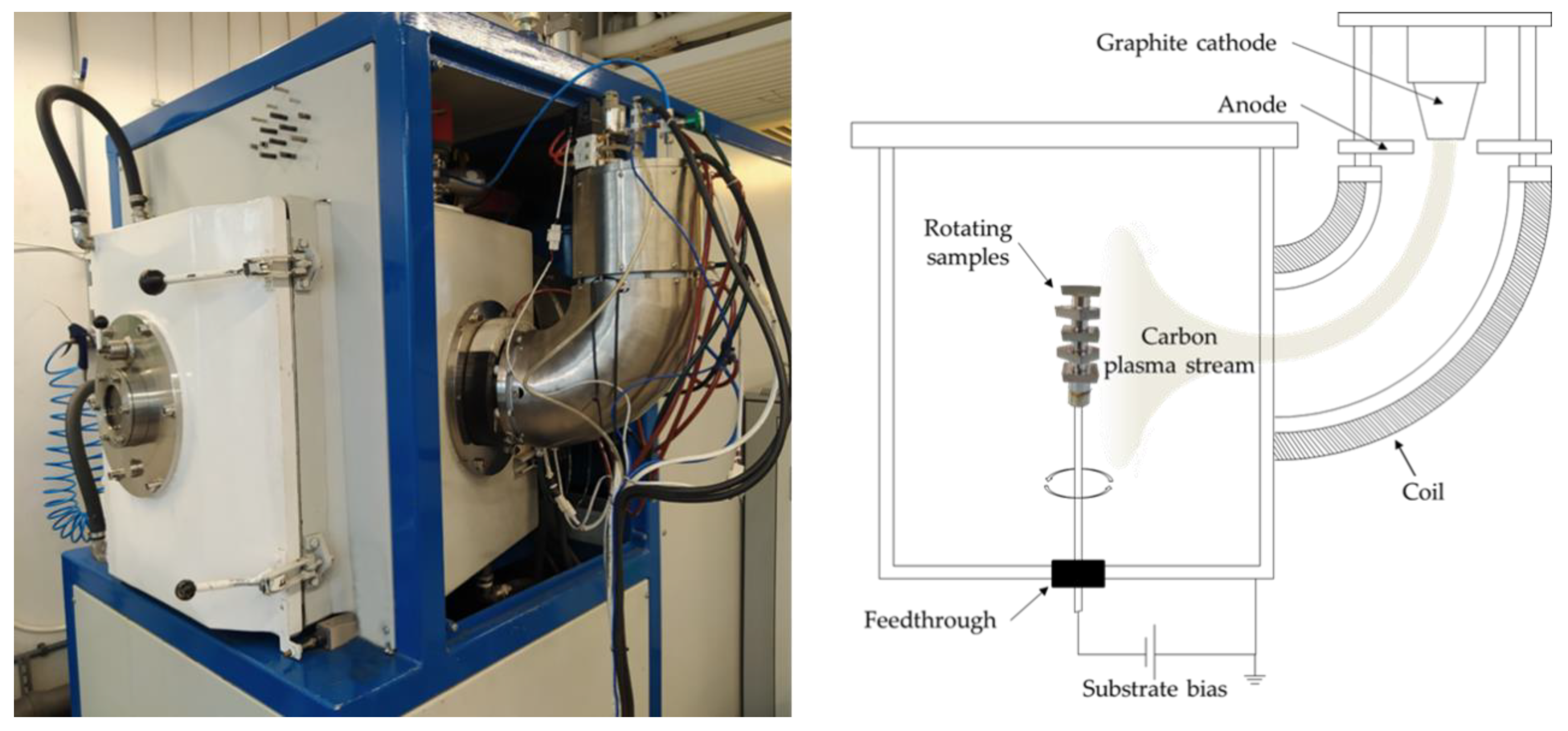
Hydrogen-free ta-C coatings were deposited on commercial tungsten carbide inserts (Canela Tools, SPUN 120308E PM25) using the cathodic vacuum arc deposition system shown in
Figure 1 (Eurecat-Tratamientos Térmicos Carreras S.A.). In order to reduce the incorporation of detrimental microparticles in the growing films, the system is provided with a DC filtered cathodic arc source (Plasma Technology Limited, Hong Kong, China), where the generated arc plasma is guided into the vacuum chamber by an electromagnetic field applied to the curved duct.
Up to five inserts were positioned in the center of the chamber (30 cm away from the duct exit) and were continuously rotated at 2.75 rpm as shown in
Figure 1. The cathodic arc source was supplied by a pure graphite cathode (99.997%). The temperature was measured using a floating K-type thermocouple placed 27 cm from the inserts.
Table 1 summarizes the experimental parameters of the different stages used for the preparation of ta-C coatings. The base pressure in the vacuum chamber was 2.6 × 10
−5 mbar. Prior to the carbon coating deposition, an argon ion etching was applied to the samples. Subsequently, a carbon bonding layer was applied by gradually decreasing the bias voltage from 1000 to 100 V over 2 min. Finally, the top ta-C coating was deposited at 50 V. The carbon arc current was maintained at 40 A. The final thickness obtained was about 0.40 μm.
It is interesting to note that unlike other DLC coatings grown on metallic or hard metal substrates, where adhesion layers based on nitrides and/or carbides of transition metals are commonly deposited, in this work, a carbon adhesion layer was applied, which simplifies the coating process.
Commercial PCD coatings with a thickness of about 9 μm and a hardness of 10,000 HV were deposited by hot-filament CVD on the same tungsten carbide inserts.
The surface morphology of the coatings was studied by Field Emission Scanning Electron Microscope (FESEM) using a Carl Zeiss Neon 40 system (Zeiss, Germany) equipped with an Energy Dispersive X-ray Spectroscopy probe (EDX).
The Daimler-Benz Rockwell-C adhesion test was used to qualitatively assess the coating adhesion. The hardness (H) of the coatings was measured using a NanoIndenter XP (MTS, Eden Prairie, MN, USA) system fitted with a Berkovich diamond tip. The tip was calibrated using a fused silica sample following the Oliver and Pharr method [
8]. The evaluation of H was conducted as a function of depth using the continuous stiffness measurement (CSM) operation mode.
The surface quality of the machined components and the hard metal inserts was assessed by measuring three roughness parameters: the arithmetical mean height for line (Ra) and surface (Sa), and the developed interfacial area ratio (Sdr). These values were measured by means of confocal laser scanning microscopy (Sensofar Plμ 2300, Terrassa, Spain). Data analysis was performed using MountainsMap 5.1 software (Digital Surf, Besançon, France) according to ISO 4287 and ISO 25178.
The turning tests were carried out on a HAAS ST-10Y CNC lathe machine, under dry conditions, cutting speed of Vc = 440 m/min, feed of f = 0.26 mm/rev and with a constant cutting depth of ap = 2 mm corresponding to the finishing conditions. The tests were carried out using 7075 aluminium alloy cylindrical samples of 250 mm in length and a diameter of 70 mm. Two samples were tested for each insert condition.
The wear of the inserts was measured in terms of adhered material. For this purpose, 3D images of cutting edge of pre- and post-tested inserts were acquired using infinite focus microscopy (Alicona InfiniteFocus SL, Graz, Austria). In addition, elemental mapping was used to compile specific chemical composition data across the rake face of the worn inserts that aimed to discern the integrity of the coating and the origin of the adhered material.
Finally, the analysis of tool vibrations produced during turning were recorded using a Piezo Star triaxial accelerometer (Kistler type 8766A, Winterthur, Switzerland) with a sampling frequency of 10 kHz. The purpose of this test was to investigate the effects of coating material and roughness on tool vibration and their correlation with the machined surface components. Thus, all the cutting parameters such as cutting speed, feed rate, depth of cut, tool and work piece length were kept constant during the test. The signal was stored on a time series database with separated tables for each experiment. The data were segmented to consider only periods where the selected tool was working, to obtain a region of interest to be analyzed. The first and last working periods were selected to compare the initial and final states of the cutting edges. Once the different time series segments were extracted, it was possible to perform a set of analyses to compare the data between each tool and cutting edge condition.
3. Results and Discussion
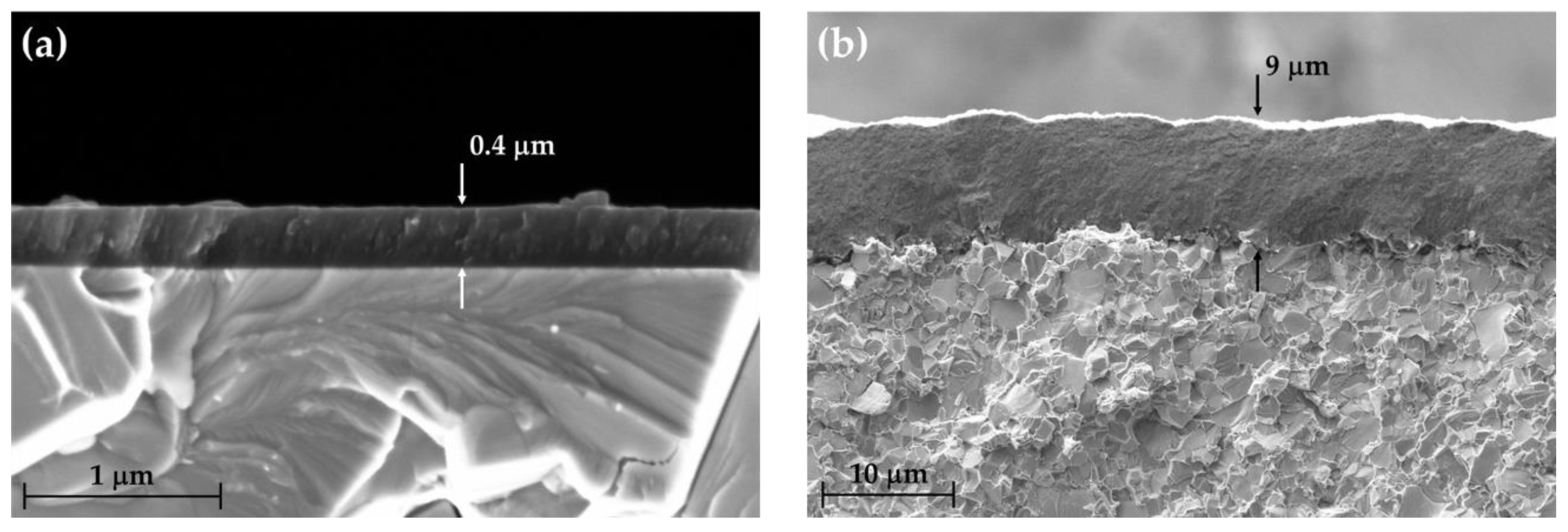
Figure 2a shows the cross-section SEM image of deposited ta-C coating, which is characterized by a dense microstructure and the presence of some surface defects that can be attributed to the small fraction of carbon microdroplets that, through multiple collisions, have escaped from the magnetic filter. It is worth noting that no carbon microparticles have been observed either at the substrate interface or within the coating. The microparticles generated by the arc discharge on the graphite cathode that have reached the substrate have been segregated towards the surface during the growth of the coating. The same phenomenon was already observed in a previous work related to the growth of silver-doped DLC coatings using a similar experimental setup [
9].
The cross-section of the PCD coating is shown in
Figure 2b. Comparatively, the PCD coating is much thicker and rougher than the ta-C coating. The roughness parameters of un-coated, ta-C-coated and PCD-coated inserts are shown in
Table 2. As can be seen, while the deposition of the ta-C coating doubles the surface roughness of the substrate, the PCD coating increases it by two orders of magnitude due to its cauliflower-like surface morphology (not shown).
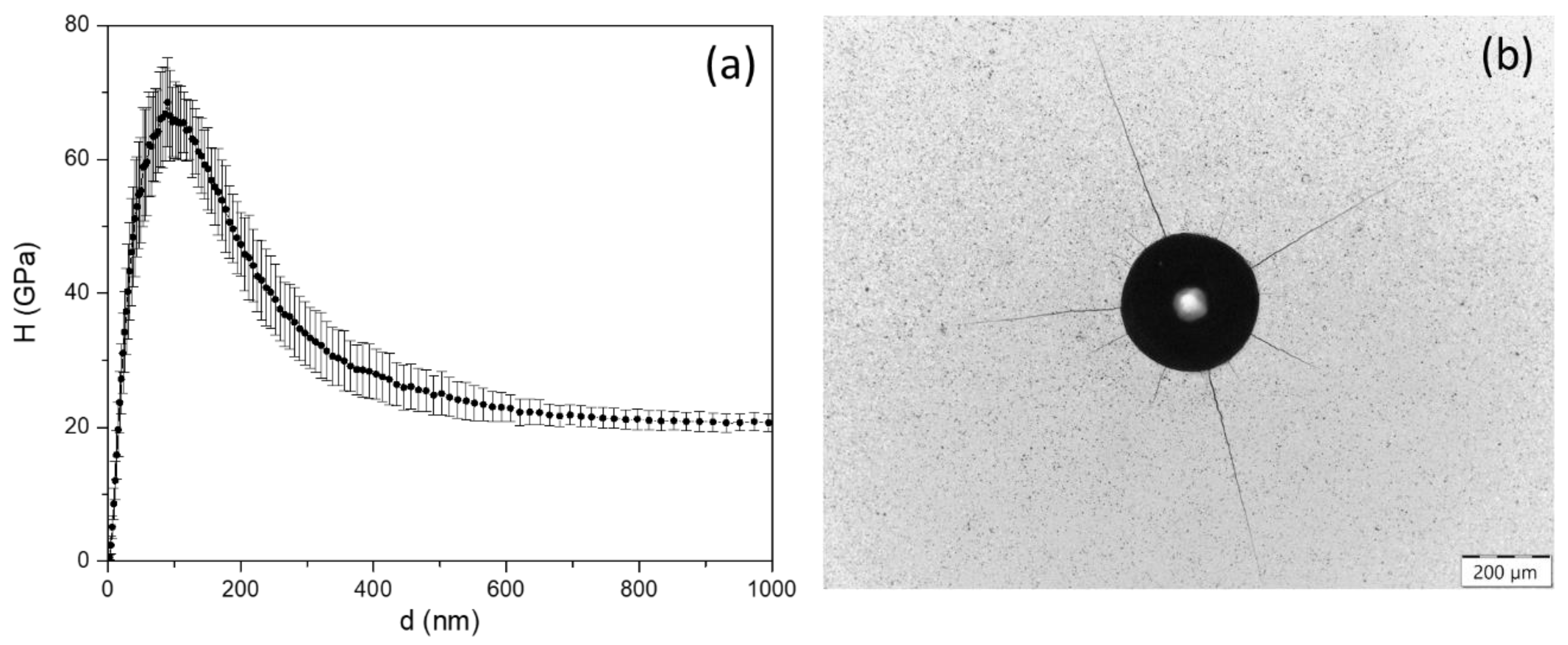
Figure 3a shows the variation of hardness as a function of the tip penetration depth obtained by nanoindentation on ta-C coating. The curve shows a maximum hardness of 68.5 ± 6.6 GPa, which can be roughly attributed to the intrinsic hardness value of the coating. In addition to this extremely high hardness, one of the most interesting results achieved in this work is the excellent adhesion shown by the ta-C coating without the application of any bonding layer based on nitrides and/or carbides of transition metals.
Figure 3b displays an optical microscopy image corresponding to the residual imprint generated by the Rockwell-C adhesion test, where no delamination has been generated.
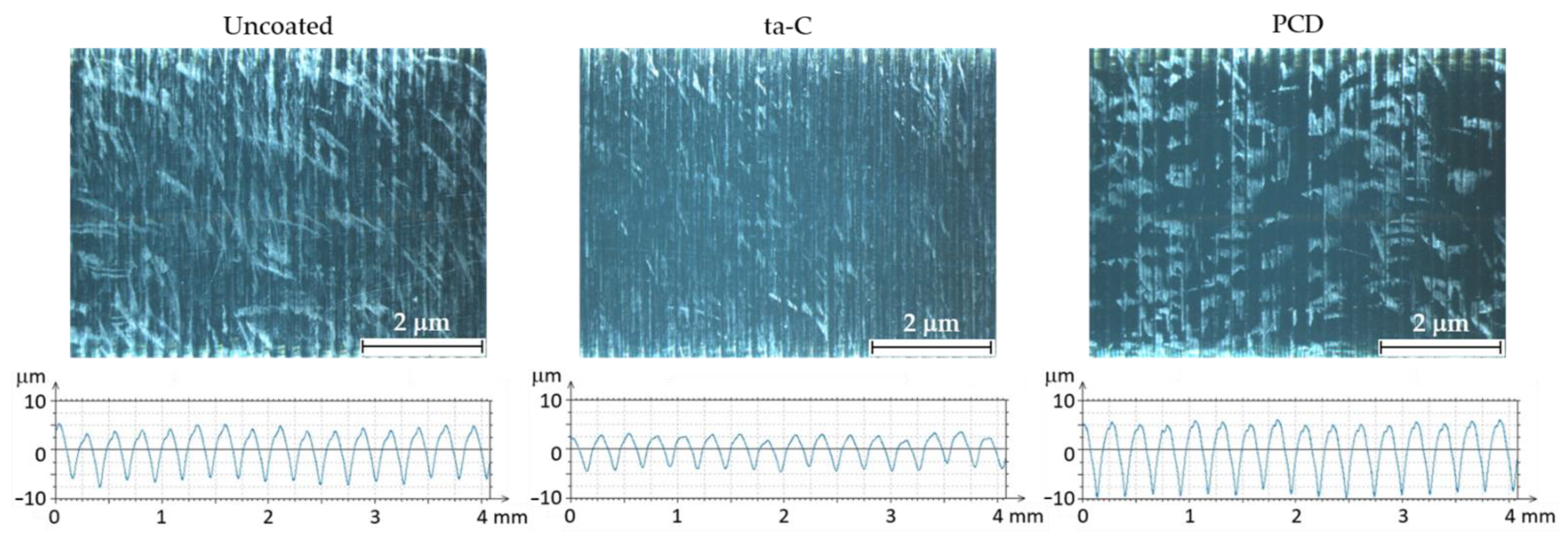
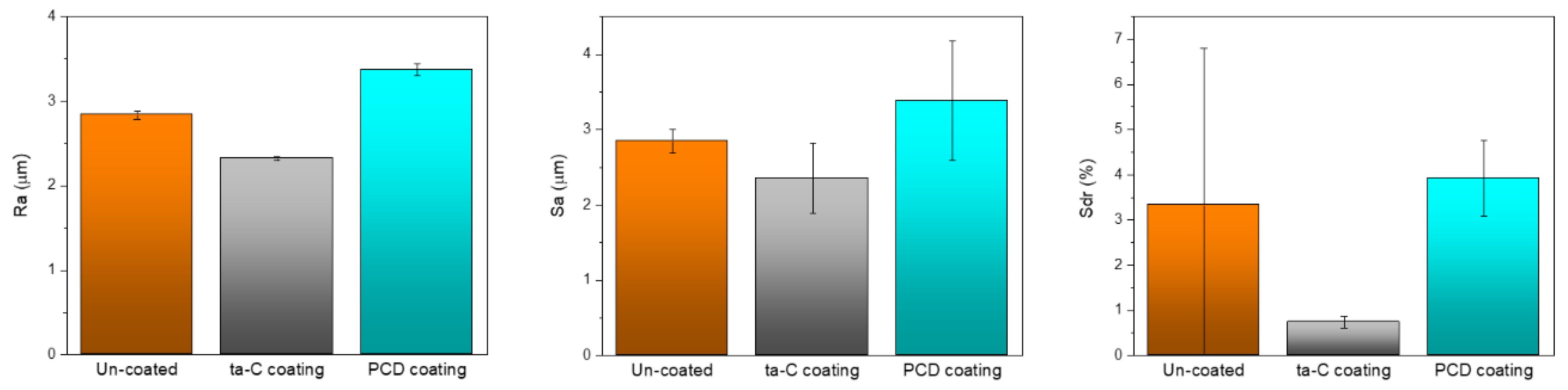
Concerning the surface quality,
Figure 4 shows optical microscopy images corresponding to the turning finish obtained using each of the hard metal inserts considered in this study. As can be seen, even with the naked eye, the best surface finish of the machined parts was obtained using ta-C coated inserts. This observation is confirmed from the measurements of the roughness parameters obtained from the machined parts, as shown in
Figure 5. After a reduction of the workpiece diameter from 70 mm to 40 mm (15 passes), the values of Ra, Sa and Sdr are significantly lower for the inserts coated with ta-C, while the worst results are obtained with the inserts coated with PCD. It should be noted that the percentage of developed interfacial area (Sdr) is the value that shows the greatest decrease in the case of ta-C coated inserts compared to un-coated and PCD coated inserts.
The machining conditions used in these experiments were quite aggressive for the cutting tool, since tests were performed under dry conditions. Despite not being useful to industry due to the reduction in tool life that this would entail, for this research, the use of dry conditions was useful to obtain information on tool wear resistance.
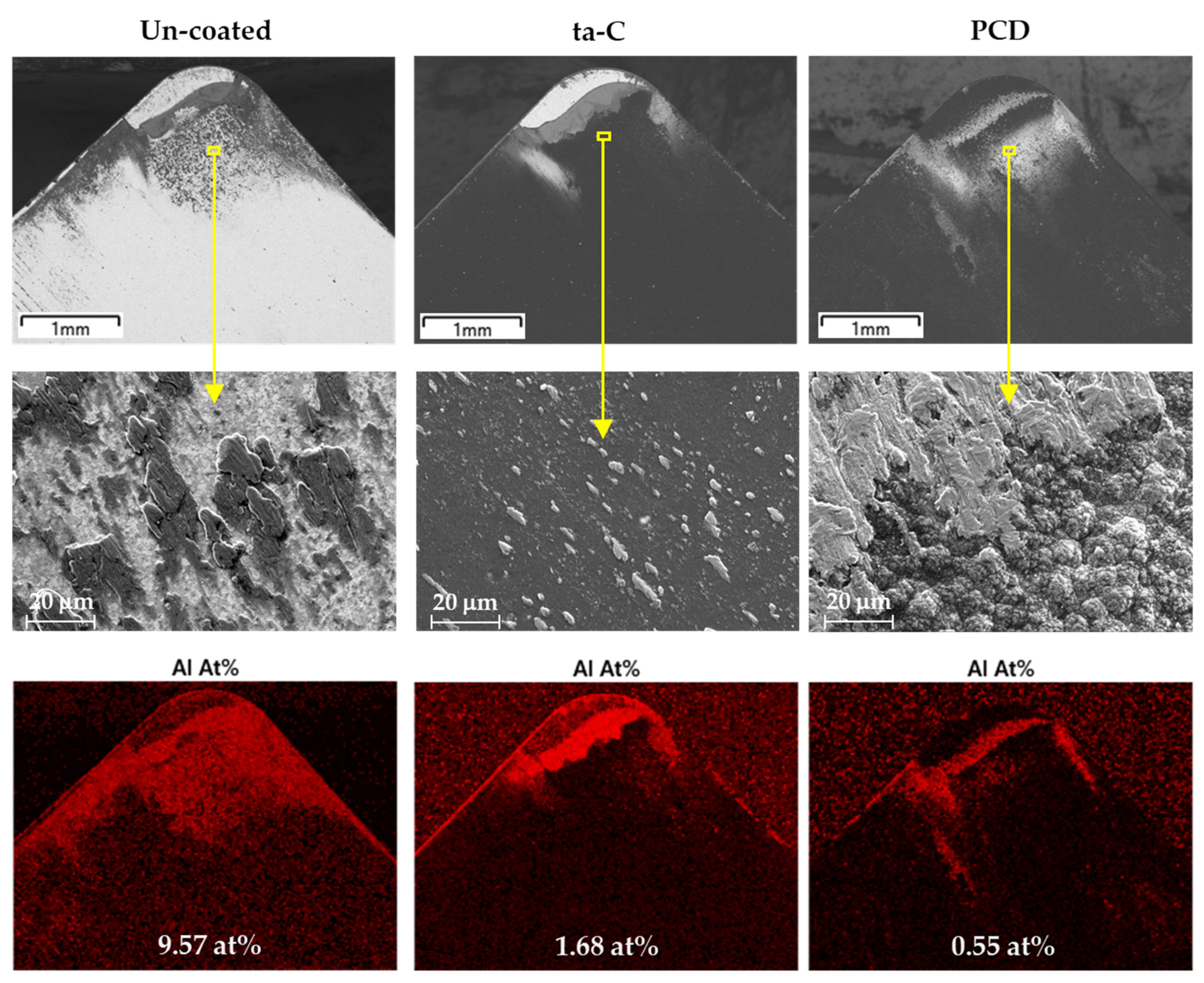
Figure 6 shows SEM images of the cutting edge of the tested inserts taken at the rake face, and their corresponding mapping element distribution and total atomic content of the adhered aluminium as determined by EDX. From these figures, it can be seen that the machining test conditions do not induce abrasive wear or severe chipping damage at the cutting edge. In addition, the test conditions reproduced the same wear area for the three inserts. However, the distribution and total atomic content of the adhered aluminium show that the un-coated insert presented a high adhesion of aluminium, homogeneously distributed over the entire contact area. On the other hand, in the ta-C-coated insert, although there is an area where the coating has partially delaminated, the content of adhered aluminium is considerably lower, and is basically concentrated in the transition between the delaminated zone and the coated area, where excessive cutting temperatures and pressures tend to increase. Finally, in the PCD-coated insert the coating remains intact (probably due to its greater thickness), showing a low aluminium content in the crater area. Despite the low atomic content of aluminium in the crater area, the element mapping shows aluminium particles mechanically adhered to the PCD coating irregularities (cauliflower-like morphology). These surface asperities induce a higher mechanical sticking which is present along the rake surface. This phenomenon has also been observed in coated tools for forming aluminium alloys [
10].
The high roughness of parts machined with PCD inserts could be attributed to the high irregular topography of the coating displayed at the cutting surface of the tool, as shown previously in
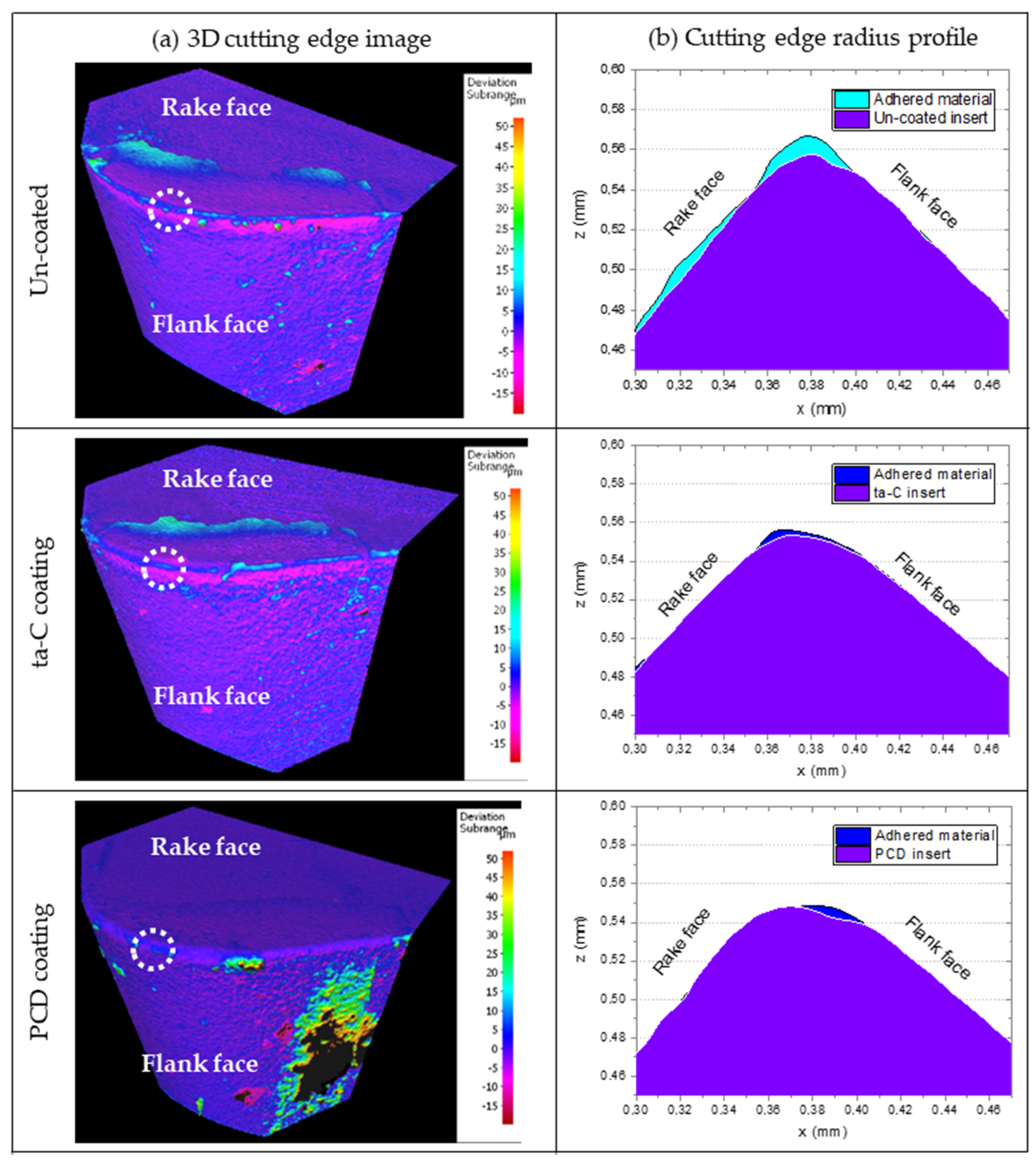
Table 2. This phenomenon is more evident in the 3D images obtained at the cutting edge of the worn inserts and their respective cross-section profiles (
Figure 7). These images were acquired automatically by comparing the reference geometry (insert in the initial state) with the worn tool (
Figure 7a). Form deviations are clearly visible by advanced color visualization scale, where the violet color indicates the reference geometry, the bright cyan color indicates the adhered material with a thickness between 10 and 20 µm, and dark blue shows the adhered material between 5 and 10 µm. The 3D images show that un-coated and ta-C inserts presented more adhered material in the rake face, as previously observed in SEM images, whereas in the flank face the maximum worn material was around 5 µm in depth, as indicated by the magenta-colored area. In contrast, the most affected area in PCD inserts was the flank face, with a large amount of adhered material, in some cases reaching a thickness of up to 50 µm.
Bi-dimensional profiles were extracted from the cutting edges radius (
Figure 7b), as indicated by the dash-line circle. Once again, the un-coated insert presents the highest material adhesion with particles up to 20 µm in size, while the radius edge of ta-C and PCD-coated inserts show adhered particles with a maximum size of 5 µm. However, PCD coated tool shows an irregular cutting edge radius due to the high roughness of the coating. Thomas et al. [
11] reported that the cutting-edge radius is one of the variables affecting the surface roughness of the machined component, interpreting the results obtained in terms of tool vibration. Nevertheless, the influence of tool surface roughness at the cutting edge was not mentioned.
The effect of tool vibrations on surface quality of machining components during the high-speed cutting process has been extensively analyzed, but these studies mainly focus on tool vibrations caused by variations in cutting parameters, geometrical cutting factors, dynamic factors, part geometries, lubricants, component materials and tools’ geometries [
12,
13]. However, the influence of the tool surface material and the roughness has not been widely reported. In previous works, authors evaluated the cutting tool vibrations for CNC turning machines using a predictive model to identify tool wearing that can affect surface integrity quality of the manufactured component [
14]. These preliminary results were orientated towards implementing a predictive maintenance methodology in inserts with the same material but with different grades of abrasive wear.
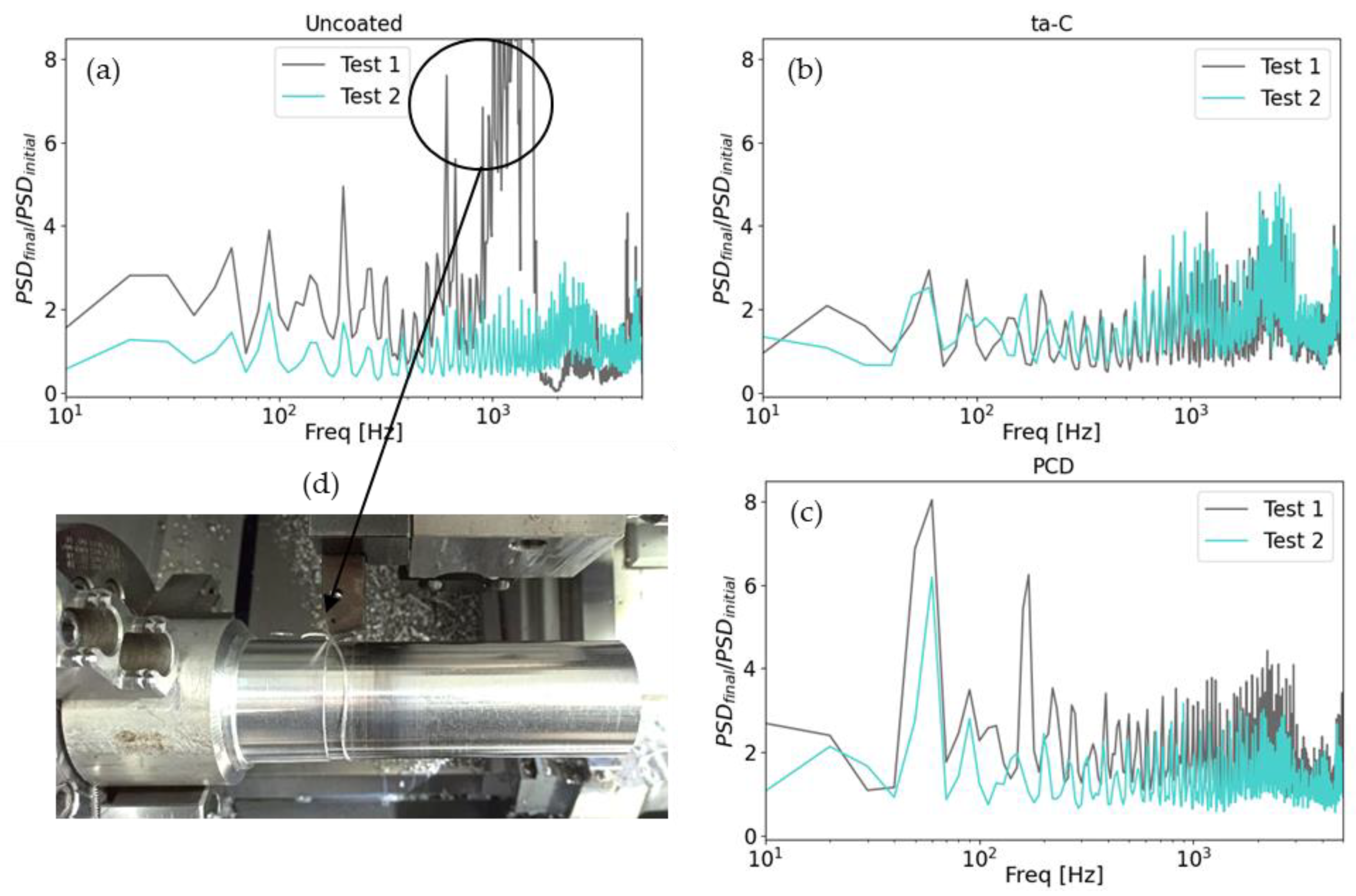
In this study, the tool vibrations were analyzed as a function of insert surface roughness and material. For this purpose, the tools were monitored using an accelerometer sensor placed in the insert holder, and all cutting parameters were kept constant. A comparative between initial and final tool state based on the vibrations generated with the accelerometer on the cutting axis can be seen in
Figure 8. The frequency spectrum for each tool signal was computed using the Power Spectral Density (PSD), which measures the spectral energy distribution over frequency, for each initial and final state. The increment on the vibration was obtained by computing the ratio between the final and initial PSD.
From the set of images, it is possible to see that the un-coated inserts suffer the most extreme wear, where the vibrations increase about 20 times between the initial state and the final state in the frequencies between 1 and 2 kHz. This increase in vibrations can be attributed to the higher amount of stuck material at the cutting edge of un-coated insert, which favors the formation of large chips around the machined component. On the other side, for PCD and ta-C coated tools, the vibrations are more stable between the first and last operation. However, the PCD-coated tools generate a larger number of harmonics, increasing vibrations by more than three times compared to the new tool in all the measured spectrums. This behavior could be attributed to high roughness of PCD coating, which, although it does not delaminate, tends to increase the adhesion of aluminium material, which is more visible in the flank face.
4. Conclusions
In view of the results obtained, for the turning conditions used in this study, it can be concluded that the super-hard ta-C coatings developed in this work using the filtered cathodic arc PVD technique offer optimal mechanical performance in terms of surface finish of machined aluminium parts. Although the low thickness of these coatings may limit tool durability compared to thicker PCD coatings, ta-C coatings may prove to be a potentially interesting alternative to PCD coatings for machining high-strength aluminium alloys, where surface finish may be as or more important than tool durability.
Vibration analysis on the tool wear supports the above hypothesis giving a clear superiority of coated over un-coated tools, and showing the need to work with coated tools. Between the ta-C and PCD coatings, the vibration shows small differences in the high-frequency range (above 1 kHz). However, for lower frequencies, the appearance of larger harmonics for the PCD coating might be generated by the higher tool surface roughness, which is also related to the higher roughness of the machined samples.

 ,
, 


