Article

Manufacturing of Aluminum Alloy Parts from Recycled Feedstock by PIG Die-Casting and Hot Stamping

1
Surface Engineering Design Laboratory, Shibaura Institute of Technology, Tokyo 144-0045, Japan
2
Sanko Light Kogyo, Co., Ltd., Kawasaki 211-0053, Japan
*
Author to whom correspondence should be addressed.
Lubricants 2023, 11(1), 13; https://doi.org/10.3390/lubricants11010013
Submission received: 7 November 2022 / Revised: 22 December 2022 / Accepted: 23 December 2022 / Published: 30 December 2022
(This article belongs to the Special Issue Tribology for Lightweighting)

Abstract

:
PIG (Pin-Injection-Gate) die-casting and hot stamping was developed for fabrication of small-sized and thin-walled aluminum alloy parts from the recycled feedstock. The pure aluminum and aluminum alloy granules were utilized as a feedstock model of recycled materials. The measured mass of granules with the estimated weight from 3D-CAD (Computer Aided Design) of products was poured into the PIG-nozzles before injection. After quickly melting by induction heating inside the PIG-nozzle units, the aluminum melts were injected into a die cavity through the PIG-nozzle. No furnaces and no crucibles were needed to store the melt aluminum stock in different from the conventional die-casting system. No clamping mechanism with huge loading machine was also needed to significantly reduce the energy consumption in casting. Much less wastes were yielded in these processes; the ratio of product to waste, or, the materials efficiency was nearly 100%. Nitrogen supersaturation and TiAlN coating were used to protect the PIG-nozzle and the stamping die surfaces from severe adhesion from aluminum melt. The pure aluminum gears and thin-walled mobile phone case were fabricated by this process. X-ray tomography proved that both products had no cavities, pores and shrinkages in their inside. Using the hot stamping unit, the micro-pillared pure aluminum heatsink was fabricated to investigate the holding temperature effect on the aspect ratio of micro-pillar height to width.

1. Introduction

A green manufacturing has grown up as a keyword in the sustainable society with carbon neutrality [1]. In the solid-state recycling [2], the used aluminum alloy parts were mechanically refined and re-alloyed to the solid preform for metal forming to fabricate new products without remelting. In warm and hot extrusion processes [3], the aluminum alloy debris fragments by machining were used as a feedstock for forward and backward extrusion to shape the recycled preforms and to drive the aluminum material circulation. The conventional die-casting process [4] is effective to make near-net shaping of remelt aluminum alloy wastes into a new product; however, it is too much energy-consuming to be utilized for green recycling. The large furnaces or crucibles are necessary to remelt the aluminum alloy wastes and to hold those remelt materials. A pair of die-sets has to be closed to drive the casting and solidification processes in the die cavity by applying the huge clamping force. Many in-process wastes, such as spurs, runners, or bosses, are inevitably yielded in daily die-casting to significantly deteriorate the aluminum material efficiency in the recycling circulation.
The PIG (Pin-Injection-Gate) die-casting system was developed to save these demerits and weak points, which are intrinsic to the conventional die-casting [5,6,7]. This new type of aluminum die-casting processes is especially suitable for near-net shaping of small-sized parts and thin-walled members. In the similar manner to the plastic injection molding, a pin-injection-gate (PIG) design is employed to cast the aluminum melts into a die-cavity. No remelting furnaces and crucible are necessary; the used aluminum alloy debris fragments with the online measured weight are directly melt in the inside of PIG-nozzle. A slightly small clamping force is enough to drive the casting and filling processes in the die cavity. The amount of in-process wastes is minimized since the online-measured materials are automatically poured into the PIG-nozzle and remelt in it. After [8], the capacity of this PIG-die casting was proved to make upward recycling of the aluminum alloy debris articles. Certainly the near-net preforms can be PIG-die-cast to yield the small-sized products, but further working steps are needed to make fine shaping and near-net shaping.
In the present paper, this PIG die-casting system is further advanced to equip the hot stamping unit to make secondary working of the PIG-die-cast preforms. The total system including these PIG die-casting and hot-stamping units, is first explained as a suitable manufacturing system to circulation of used aluminum alloys. Two types of surface treatment are utilized to prevent the PIG-nozzle units as well as the dies from adhesion wear during the PIG-die casting and hot stamping; nitrogen supersaturation process and TiAlN coating. The PIG die casting behavior is described by free-injection and short-shot casting experiments. The miniature pure aluminum gear is die-cast by using a single PIG-nozzle unit. The aluminum alloy mobile phone case is also die-cast by using double PIG-nozzle units. The pure aluminum heatsink is fabricated by warm and hot stamping the PIG-die-cast aluminum preform to have the micro-pillared microtextures on its surface. This aluminum manufacturing process has a capacity to fabricate the small-sized and rib-structured aluminum alloy parts from the crashed fragment feedstock and to play a significant contribution to light-weight part design.

2. Materials and Methods

The PIG die-casting unit is combined with the hot stamping unit to build up the green aluminum processing for upward recycling from the aluminum machined chips and fragments to small sized parts and thin-walled products. Through alternative combination of two units, various light-weight metal forming procedures are available to fabricate the upward-recycled products. The plasma nitriding was mainly utilized for protection of PIG-nozzles and dies from galling by aluminum melts. In particular, the micro-textured die is prepared for warm and hot stamping by using the plasma printing method to prepare the mesh-patterned punch.

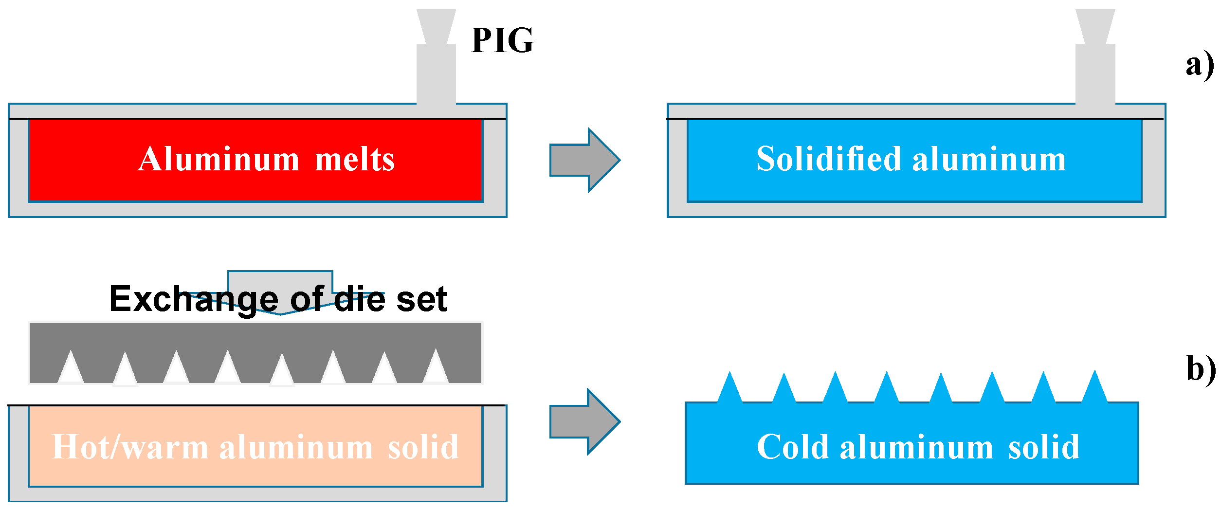
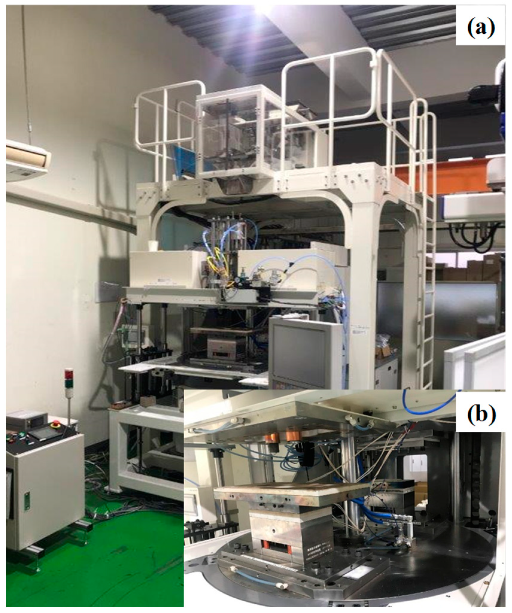
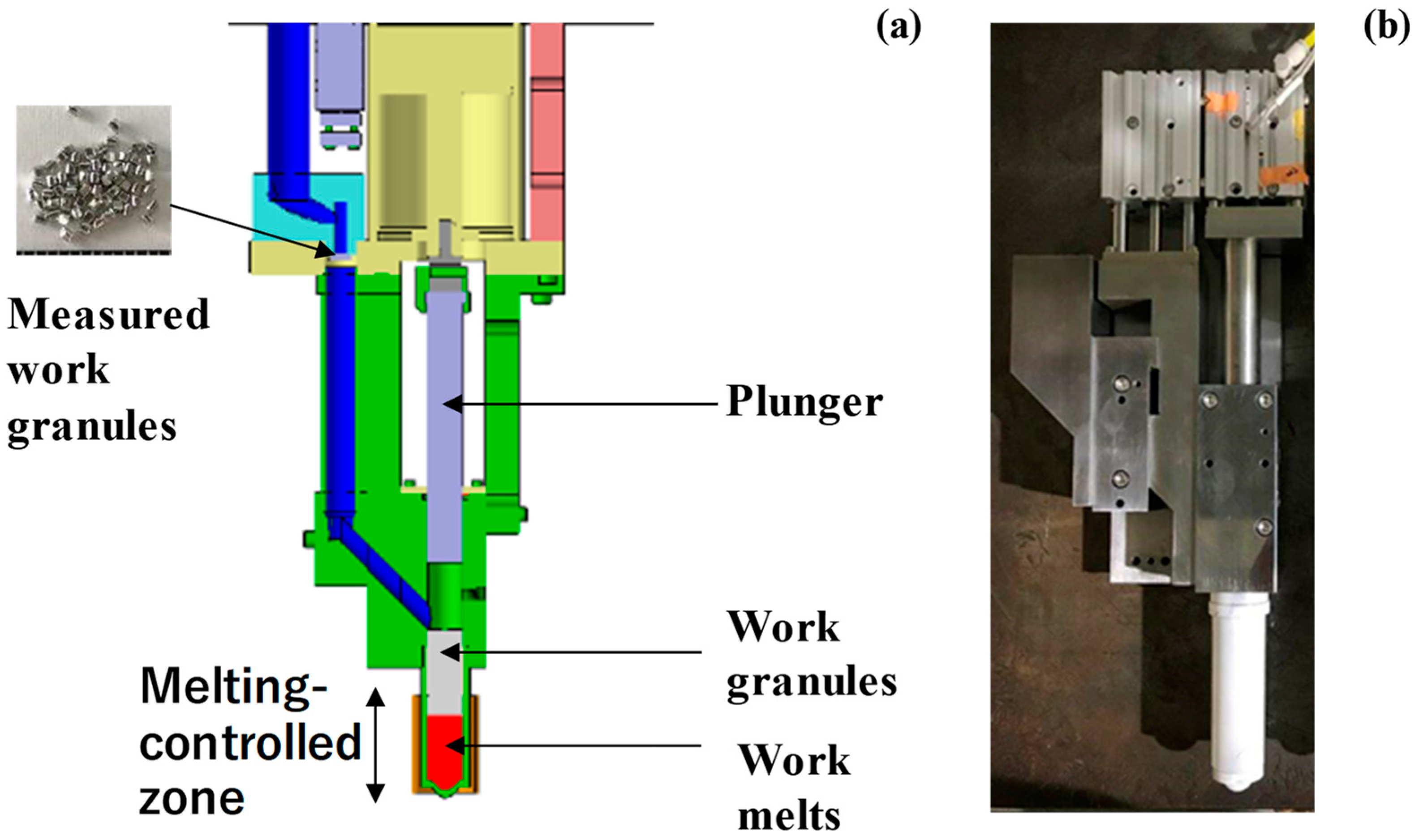
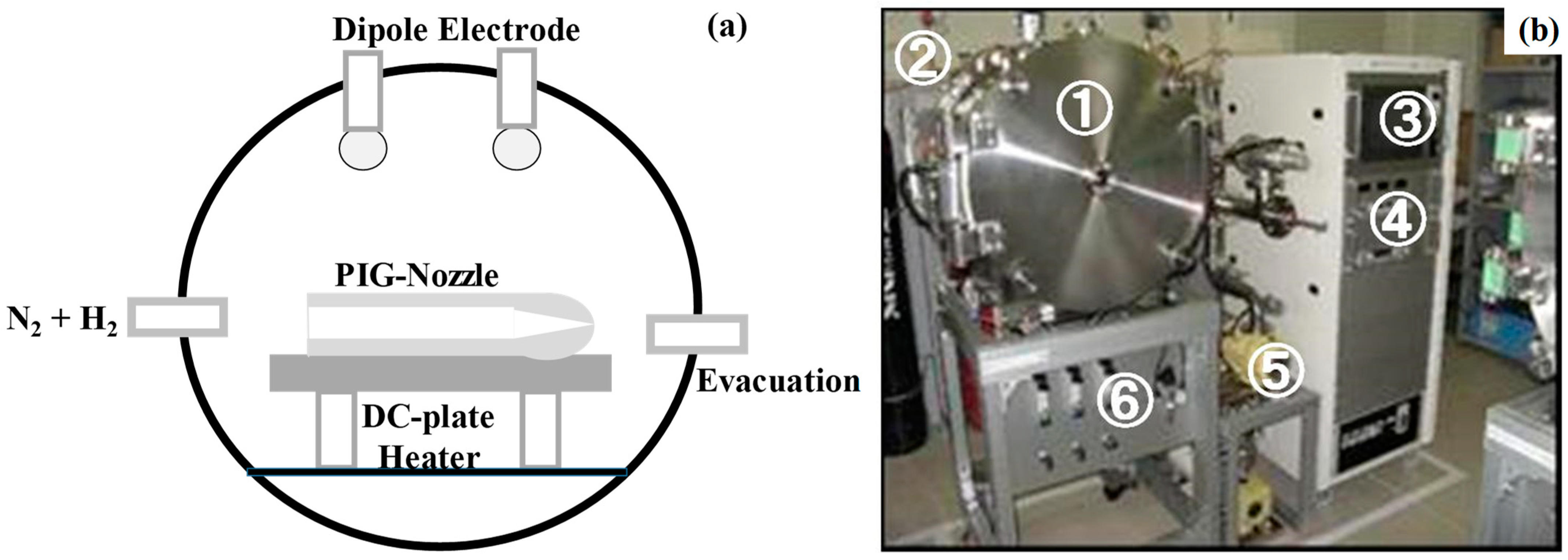
2.1. New Aluminum Manufacturing System by PIG Die-Casting and Hot Stamping

In the present aluminum manufacturing system, the PIG die-casting unit is combined with the hot stamping unit. The die-set is exchanged from one unit to another one by controlling the rotating bed. Various working procedures are possibly designed and accommodated to this system, as illustrated in Figure 1.
In the PIG die-casting in Figure 1a, the aluminum melt is cast into the die cavity and cooled down to yield the near-net shaped product. This is a standard procedure to make near-net shaping of small-sized and thin-walled aluminum alloy parts. The PIG die-cast preform is further hot stamped to the micro-textured product under the specified holding temperature as illustrated in Figure 1b. Figure 2a depicts the overview of developed manufacturing system. Using the rotating bed in Figure 2b, the lower die-set including the primarily processed aluminum preform is transferred to the secondary step. In this secondary step, a new upper die-set is utilized for further processing. Let us explain the key techniques in this system.
In the PIG die-casting unit, the aluminum melt is injected through the PIG-nozzle into the die cavity. As illustrated Figure 3a, the aluminum and aluminum alloy granules and their used fragments are utilized as a feedstock for casting. The weight of starting granular materials is on line measured with reference to the product volume data in the 3D-CAD (Computer Aided Design) model of product. The measured materials are poured and stacked into the PIG-nozzle unit. The stacked work is melt rapidly and uniformly by using the IH (Induction Heating)-coil with the designed high frequency of 500 kHz. After monitoring the temperature transients during heating, the work melt is pushed into a die cavity by using the pressurizing media. Figure 3b shows the actual PIG-nozzle unit.
In the warm and hot stamping unit, the upper die-set including the micro-textured punch is prepared for net-shaping. This die set is fixed into the upper bolster of stamping unit; its stoke is directly controlled to move down and up the upper die-set after programmable sequence for loading and unloading, respectively. In the following stamping experiment, the stroke speed is constant by 0.1 m/s.
As had been discussed on the hot extrusion studies of aluminum alloys [9], the aluminum remelt as well as hot preform were easy to adhere onto the die inner surfaces. Without surface treatments, the inner surface of PIG nozzle and dies could experience severe adhesive wear. To be free from galling and erosion by aluminum melts, the inner surface of PIG-nozzle was protected by the low temperature plasma nitriding [10] and TiAlN-base coating [11].

2.2. Tribological Treatment for PIG-Nozzles and Dies

The low temperature plasma nitriding was first utilized to form a thick nitrogen supersaturated layer into the inner surfaces of PIG-nizzles and the die surfaces and to save them from the corrosion and erosion wear by chemical attack of aluminum melts. RF (Radio-Frequency)–DC (Direct Current) plasma nitriding system (YS-Electrical Industry, Co., Ltd.; Kofu, Japan) was utilized for this nitrogen supersaturation treatment of AISI420J2 PIG nozzles and dies at 673 K for 14.4 ks by 70 Pa. Figure 4 depicts this plasma nitriding system. As illustrated in Figure 4a, the inner surface of PIG-nozzle was directly nitrided by using the nitrogen and hydrogen mixture gas. The nitriding temperature was monitored by using the thermocouple, embedded into the DC-plate. The pressure was also controlled by using the gas flow meter. The deviation of temperature and pressure was reduced within ±0.1 K and ±0.05 Pa, respectively.
The PIG-nozzles were first nitrogen-supersaturated under the nitriding conditions. After nitriding, TiAlN film was deposited onto the PIG-nozzles by PVD process. Its thickness was 3 μm. The dies for casting and warm/hot stamping processes were only nitrogen supersaturated to harden their surfaces up to 1400 HV by the thick nitrided layer of 50 μm.

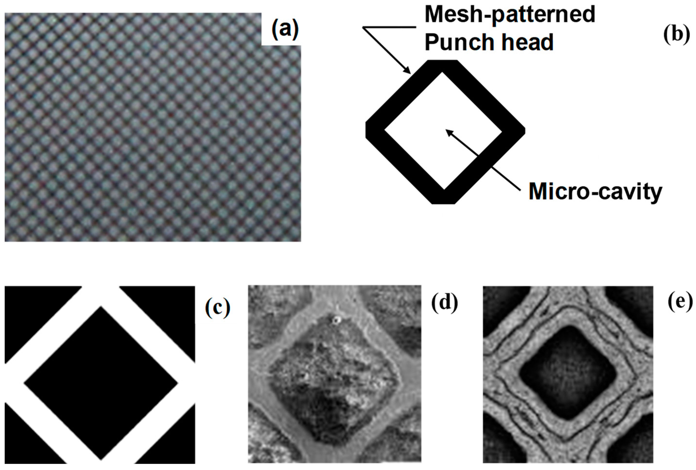
2.3. Warm and Hot Stamping Die for Microtexturing

An AISI316 punch for microtexturing the PIG-die-cast preform was prepared by plasma printing [12]. The screen printer was first used to draw the two dimensional pattern onto the punch surface as a mask. The low temperature plasma nitriding [10] was also employed to make nitrogen supersaturation onto the unmasked surface areas for selective hardening. The sand-blasting was utilized to mechanically remove the unmasked and un-nitrided AISI316 matrix of punch and to shape the designed microtextures onto the AISI316 punch.
In order to build up the AISI316 punch for hot-stamping the micro-pillared aluminum heatsink, the punch surface was shaped to have the mesh-patterned multi-heads with micro-cavities [13]. As depicted in Figure 5a, this mesh-pattern was designed by regular alignment of rectangular unit-cell in Figure 5b. The black-colored edges in Figure 5a,b, become a punch head while the white colored square corresponds to a micro-cavity, into which the aluminum work flows in the backward extrusion during the hot stamping. The screen film was first prepared to print the negative pattern to the designed microtexture in Figure 5a onto the punch surface. Its unit cell is shown in Figure 5c, where the white colored square in Figure 5b is printed in black and the black colored edge in Figure 5b are never printed. Since those printed zones work as a mask in the plasma nitriding, the white edge zone in Figure 5c is selectively nitrided in Figure 5d. After sand-blasting with the use of silica particles, the printed part in Figure 5d is mechanically removed to form the mesh-patterned punch heads, as depicted in Figure 5e.
After the procedure in Figure 5, the mesh-textured AISI316 punch was shaped as shown in Figure 6a. Its surface consists of the mesh-textured multi-heads in Figure 6b; the maximum surface roughness on these punch heads was only 0.6 μm. This proves that the as-blasted AISI316 punch is directly used as a warm and hot stamping punch without further polishing. Three dimensional profile of this microtexture on the punch is shown in Figure 6c. The maximum depth of micro-cavities reaches 190 μm, which is deep enough for micro-extrusion of aluminum work during hot stamping.
During this hot and warm stamping, the mesh-textured AISI316 punch has a risk of galling, where the hot aluminum preforms flow into the cavities in Figure 6. Through the plasma printing process in Figure 6, the AISI316 punch surfaces were also nitrogen supersaturated at 673 K for 14.4 ks by 70 Pa. After [10,14], these surfaces were expected to have sufficient corrosion and erosion toughness enough to be free from the adhesion of aluminum flow and chemical attack to the punch surfaces.

2.4. Work Materials

The aluminum granules with the purity of 99.7% and the size of 3 mm were prepared as a pure aluminum feedstock. AA5052 aluminum alloy particles were also utilized for mass-production of thin parts. The chemical composition of this alloy is listed in the following: e.g., 2.6 mass% Mg, 0.10 mass% Zn, 0.25 mass% Si, 0.4 mass% Fe, 0.10 mass% Cu, 0.10 mass% Mn, 0.25 mass% Cr, and Al in balance. The PIG-nozzle and casting dies were made from AISI420J2 while AISI316 was used for the warm/hot stamping dies.

2.5. Measurement and Characterization

A table-top X-ray tomography apparatus was employed to make non-destructive evaluation on the residual defects in the cast aluminum and aluminum alloy products. The laser microscopy and three dimensional profilometer were utilized to measure the concave and convex microtextures on the plasma-printed AISI316 die and the hot-stamped aluminum plates, respectively.

3. Results

Pure aluminum and A5052 granular particles were employed as a feedstock material for PIG die casting and hot stamping. Small-sized parts such as pure aluminum gears were die-cast to demonstrate that these are yielded with less amounts of waste and without residual pores and defects. The aluminum mobile phone case was also die-cast to prove that thin-walled parts are fabricated even in mass-production. The pure aluminum heatsink was fabricated by the two-step procedure.

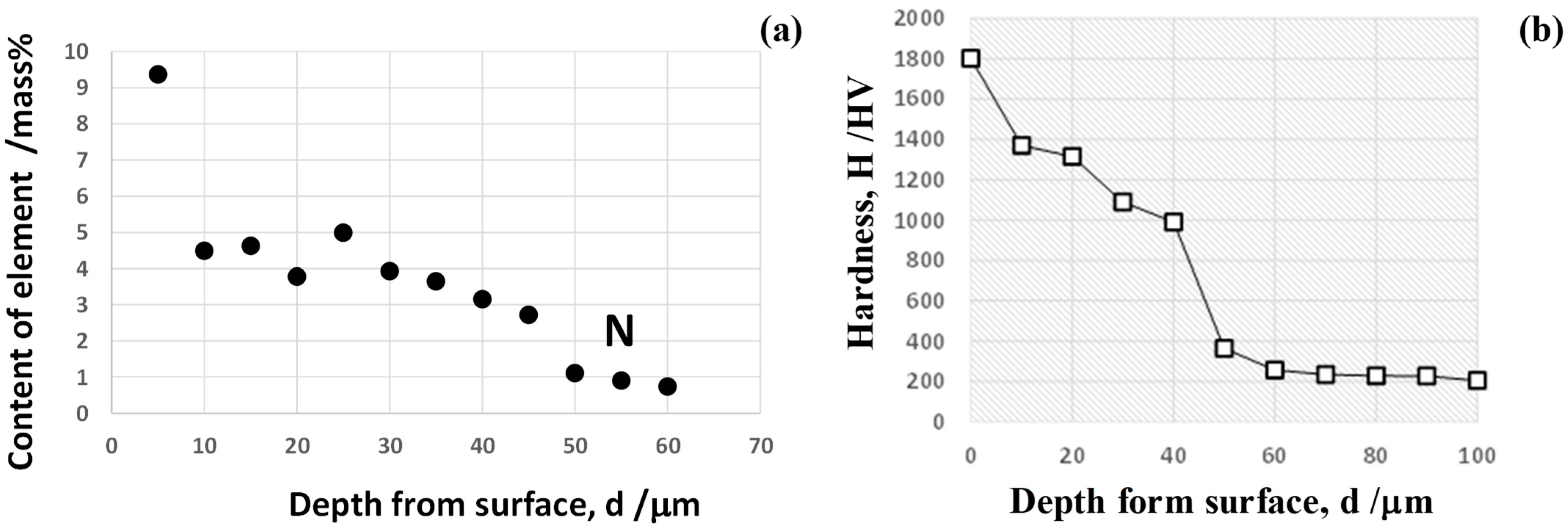
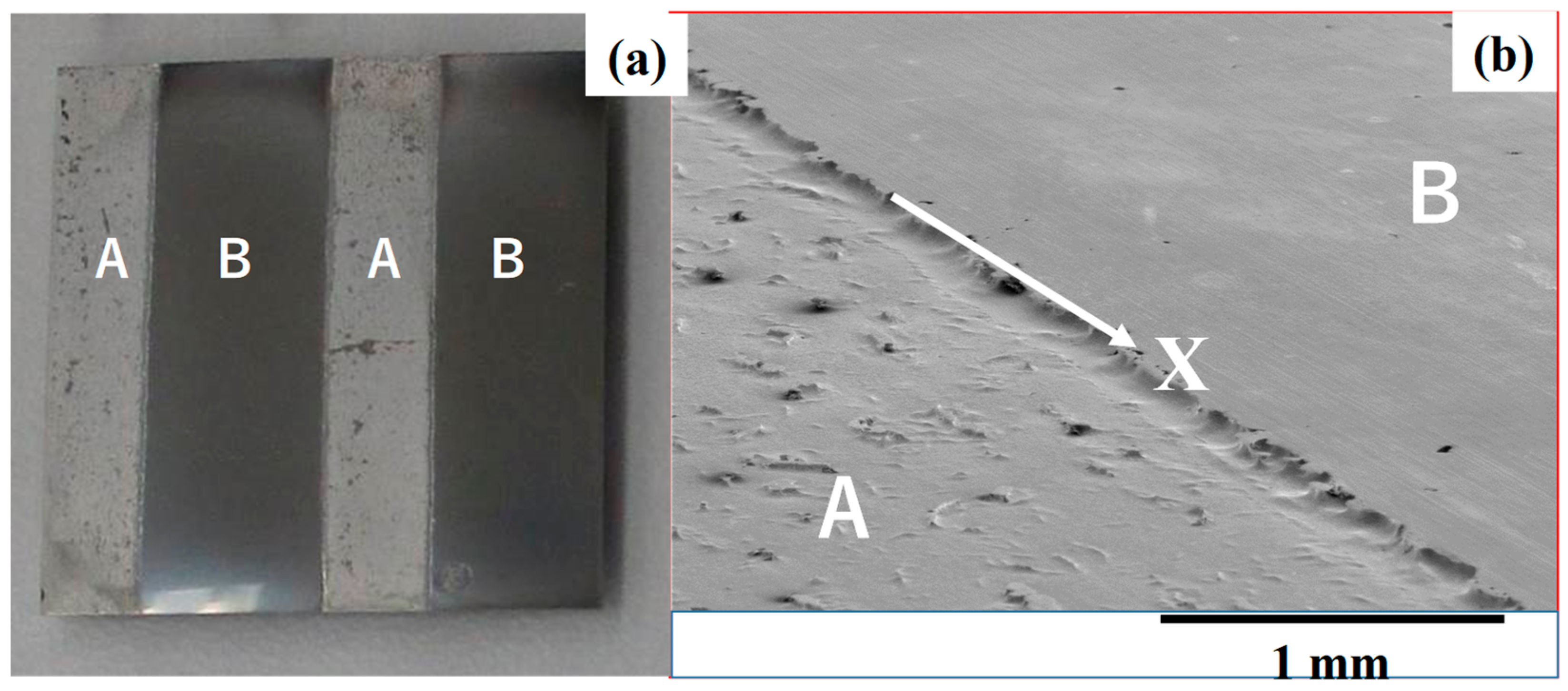
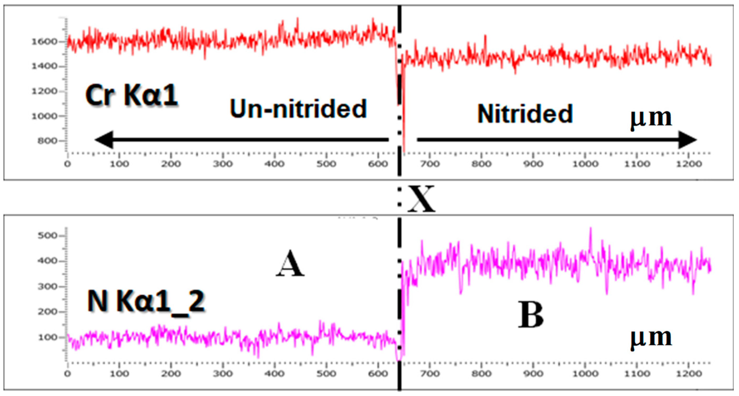
3.1. Tribological Characterization of Nitrided AISI420J2

The hardness and nitrogen solute content were measured by the micro-Vickers hardness testing and SEM (Scanning Electron Microscopy)-EDX (Energy Dispersive X-ray spectroscopy), respectively. As depicted in Figure 7, the nitrogen content more than 3 mass% and higher hardness than 1000 HV were preserved in the nitrided layer with the thickness of 50 μm. In particular, most of octahedral vacancy sites in AISI420 crystalline cells were occupied by the nitrogen interstitial atoms in this high average nitrogen content of 3 mass%. After experimental studies in [10,14] and theoretical study in [15], the corrosion and erosion toughness is expected to be improved by this thick nitrided layer.
The hydrochloric acid with 20% concentration was used for dipping test at RT for 600 s to investigate the difference of corrosion and erosion toughness between the un-nitrided and nitrided AISI420J2. As depicted in Figure 8, the un-nitrided surfaces “A” were selectively etched while the nitrided surfaces “B” were never etched. After dipping test, SEM-EDX was also utilized to analyze the chromium and nitrogen content distribution from “A” to “B” across the boundary “X”. Figure 9 reveals that no change was detected in the chromium profile across “X” but that the nitrogen content jumped up across “X” in correspondence to the microstructure in Figure 8b. This high corrosion and erosion toughness proves that both the nitrided PIG-nozzle and die surfaces have sufficient wear toughness against the chemically attacking gaseous and liquid components.

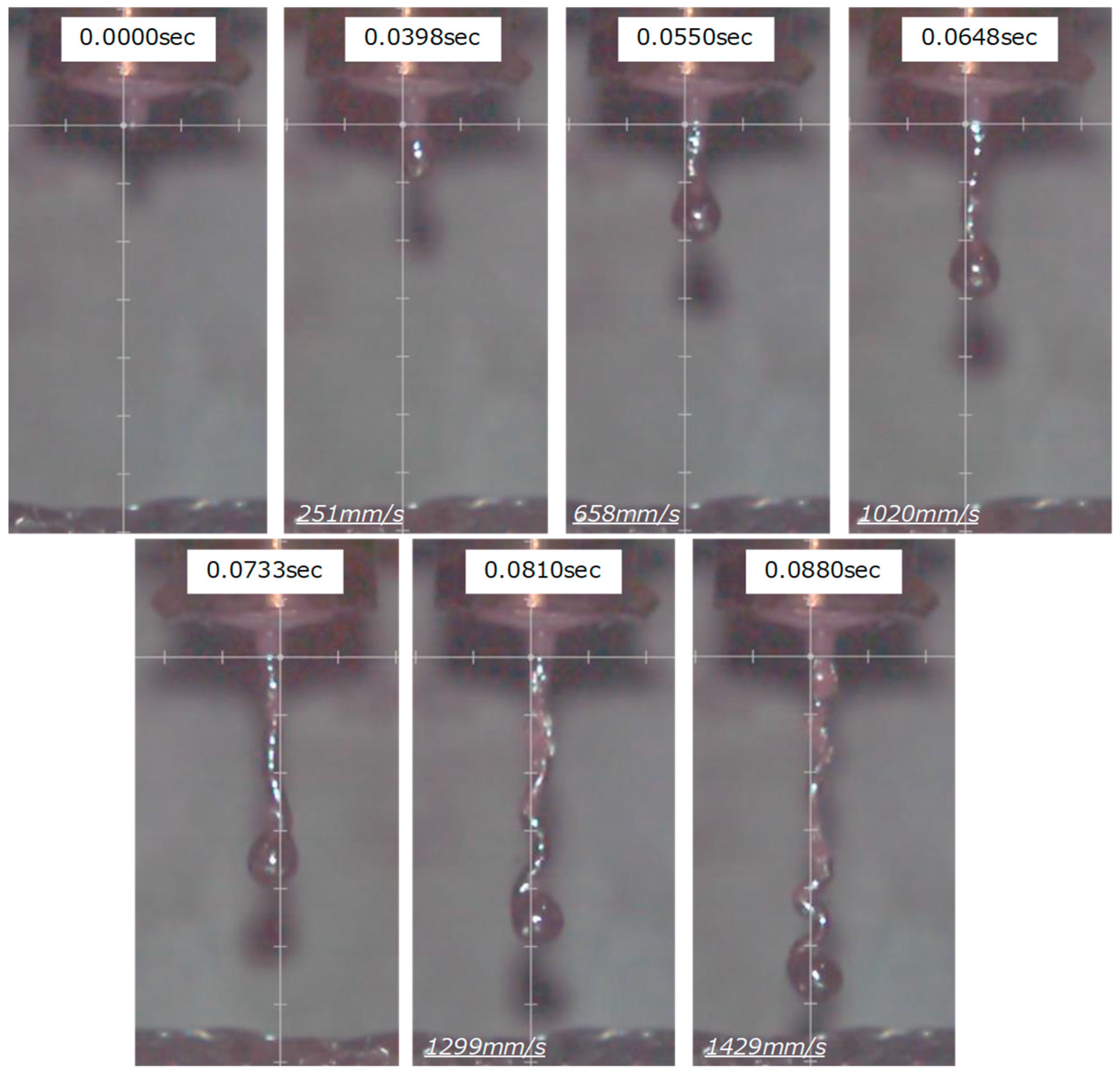
3.2. Free Injection Behavior through a Single PIG-Nozzle Unit

In the similar manner to the normal die casting process, the PIG die casting process has a capacity to make fast-rate and stable injection of aluminum melts from the PIG-nozzle gates to the die cavity. The free injection experiment from the PIG-nozzle gate to the flat bed was performed to describe the dynamic flow behavior of pure aluminum melts. The high-speed video camera was utilized to monitor the streaming melt flow in this free injection experiment. A single PIG-nozzle unit was used in this experiment.
Figure 10 depicts a series of video frame-images from the onset of injection through the PIG-nozzle gate. An aluminum melt flow, streams from the outlet gate of PIG-nozzle straightforwardly against the flat bed. At the beginning, the melt started to stream in relatively low velocity due to the mechanical constraint by the PIG-nozzle gate. This flow rate was accelerated with time up to the terminal speed of 1450 mm/s. The average injection velocity was estimated to be 800 mm/s or 0.8 m/s. As discussed in [16], the slowest injection speed ranged from 0.1 to 0.8 m/s, and the highest injection speed reached 40 m/s. The present injection capacity is equivalent to the normal die casting class with the medium injection speed. Due to the gravity, a spherical ball was formed at the front end of aluminum melt stream in this free injection experiment. In practical die-casting, the aluminum jet stream shots onto the die walls and spreads into the die cavity.
Further CAE (Computer Aided Engineering) analysis is needed to optimize the aluminum and aluminum alloy melt flow in the die cavity. A hydrodynamic modeling provides a way to understand the effect of velocity profile of melts on the filling process as suggested in [17].

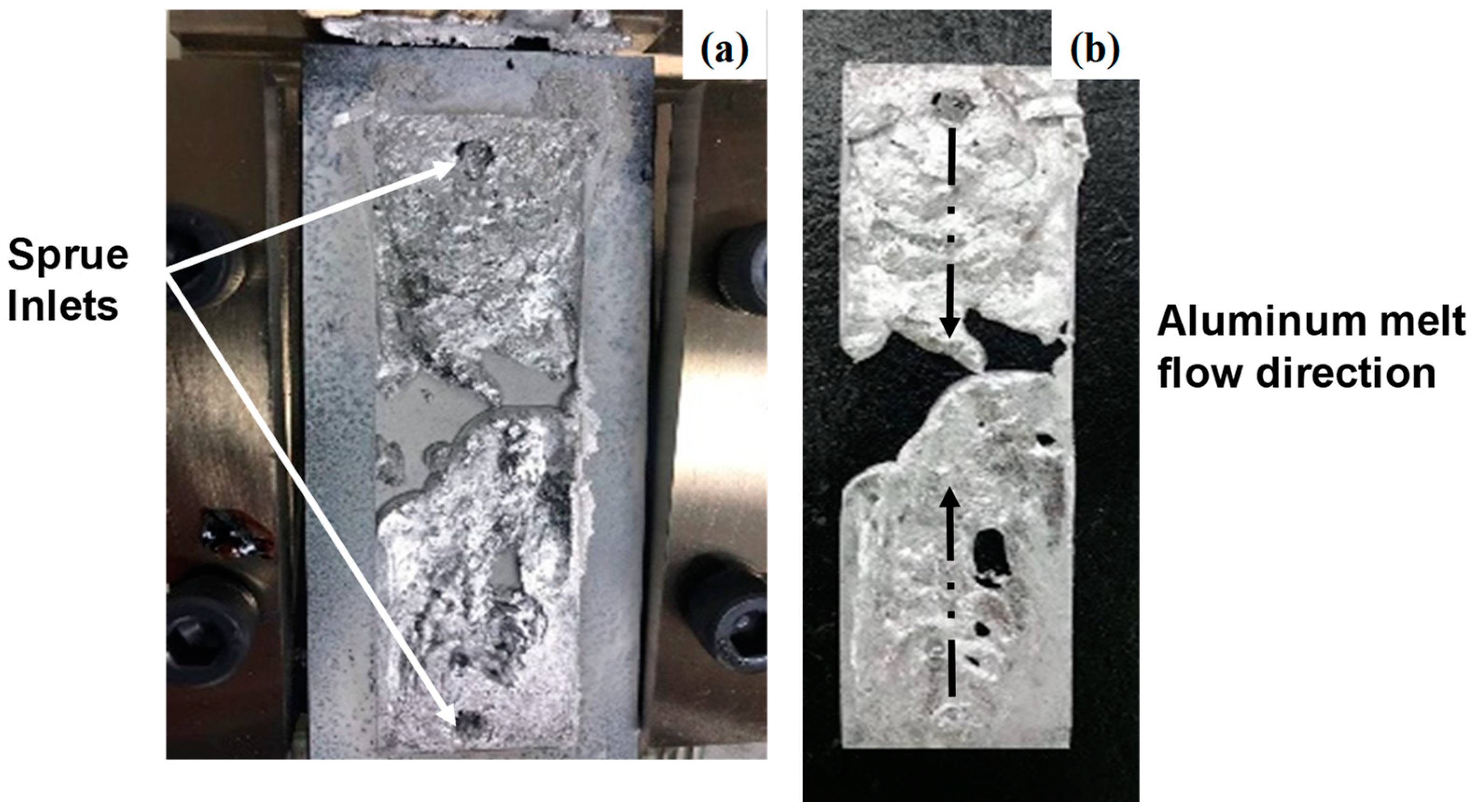
3.3. Aluminum Flow into a Die Cavity

The short-shot experiment [18] was used to investigate the aluminum melt flow in the die cavity. The double PIG-nozzle units were employed to pour the pure aluminum granules into two PIG-nozzles and to inject the aluminum melts from double PIG-gates into a die cavity. The die cavity was shaped to be rectangular. Figure 11a shows the aluminum flow pattern in the die cavity. The injected aluminum melts from the double gates flew from each end to the center of die cavity. As seen in Figure 11a,b, both ends of cavity near the inlets were first filled and both aluminum melts flew from both ends to the center of cavity with nearly the same speed. This flow pattern is similar to the potential flow mode of plastic melts in the plastic mold injection process as precisely stated in [19].
As slightly stated in [16,17], the quality of die-cast aluminum alloys parts is dependent on the degassing of residual air from the die cavity and the lubrication on the die surfaces. In the present system, the nitrogen gas was blown before PIG die-casting to minimize the contamination of gaseous components into the cast aluminum. The inner surfaces of die cavity were nitrogen supersaturated at 673 K for 14.4 ks by 70 Pa. Due to its hardness and corrosion toughness stated in 3.1, the dies are free from adhesion of aluminum melts onto the dies even without the use of solid lubricants.

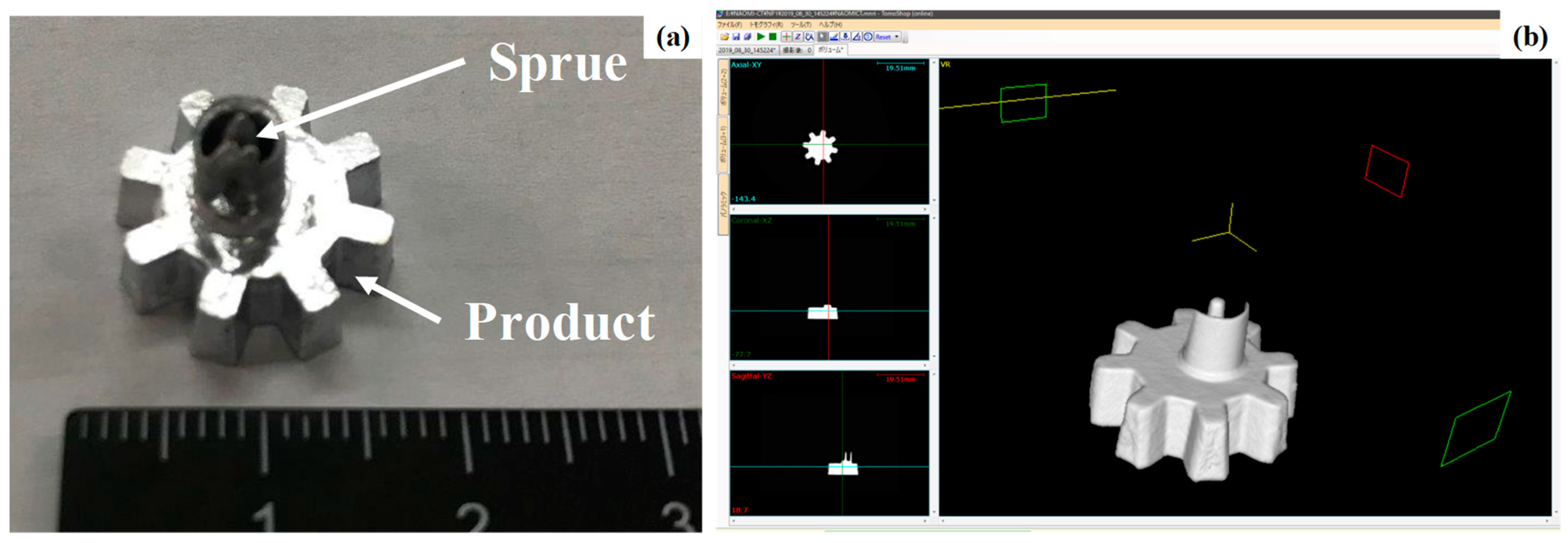
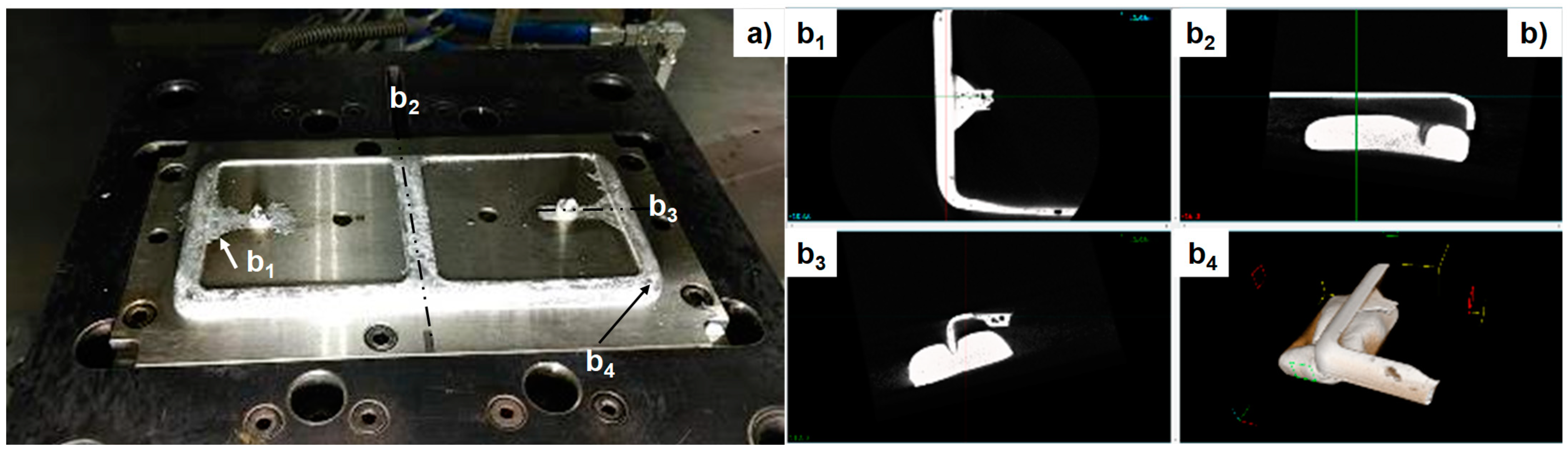
3.4. PIG Die-Casting of AA5052 Small Parts by Using a Single PIG-Nozzle Unit

This PIG die casting unit was first utilized to fabricate the small-sized aluminum parts using a single PIG-nozzle unit. A pure aluminum gear with eight teeth was selected as a targeting product. As reported in [20], most of automatic robotic arms require a light-weight, small-sized gears in the precise transmission system. Among them, the aluminum and aluminum alloy gears are demanded in the market together with the engineering plastic gears.
The die-set for PIG die casting was simply prepared by machining the lower die to have a gear-shaped cavity as well as the upper die-plate to have a sprue as an inlet of injection. Figure 12a depicts the pure aluminum gear which was fabricated by the PIG die casting. No burrs except for the sprue were formed with the gear product.
The X-ray tomography was utilized to make nondestructive inspection on the inner defects and pores in the inside of the PIG-cast aluminum products. Since the X-ray penetration was much sensitive to the change of mass densities, the inner defects and pores were easily detected as a black zone against the white zones for dense materials. In addition, the sample was rotated under the X-ray beam irradiation from the fixed window; the three dimensional mass-density image was directly obtained for diagnosis of defects. Figure 12b depicts the three dimensionally constructed X-ray image in bird-eye view for the cast aluminum gear together with its three cross-sections. Each tooth is accurately shaped in trapezoidal to be working as a skewed gear. Three cross-sectional images prove that no pores and defects are left in the inside of cast gear. The near-net preforms of spur-gear and bevel-gear can be accurately formed by this PIG die-casting before finishing process.

3.5. PIG Die-Casting of Aluminum Mobile Phone Case Using a Double PIG-Nozzle Unit

Fine machining and die-casting have been utilized for mass production of aluminum mobile phone case with the shielding capacity of electromagnetic waves [21]. Due to a market demand for the recyclable low-weight parts, this aluminum mobile phone case was redesigned to reduce the weight as much as possible and to strengthen the stiffness for protection of electric parts. The thin-walled structuring design is often selected in manufacturing. The conventional metal forming processes were difficult to make thin-walled structures; the fine machining process was selected for mass-production of aluminum mobile-phone cases.
The mobile phone case model with the size of 200 mm x 120 mm and the minimum thickness of 0.5 mm, was employed to prepare the upper and lower die sets for PIG die-casting. Double PIG-nozzle units were utilized to inject the AA5052 aluminum alloy melts through two gates into the die cavity. Figure 13a depicts the cast and solidified AA5052 mobile phone case model. No burrs were also yielded except for the sprues and runners; the materials efficiency reaches 98% of poured AA5052 fragments into double PIG-nozzles. X-ray tomography was also utilized to make nondestructive evaluation on the integrity of four sections in the case model. The clay was utilized as a support of thin-walled aluminum case. No pores were also detected in every four section in Figure 13b. As depicted in Figure 13b2, the flat support panel with the thickness of 0.5 mm was uniformly shaped by this forming. Figure 13b4 proves that curved thin-walled panel was also net-shaped.

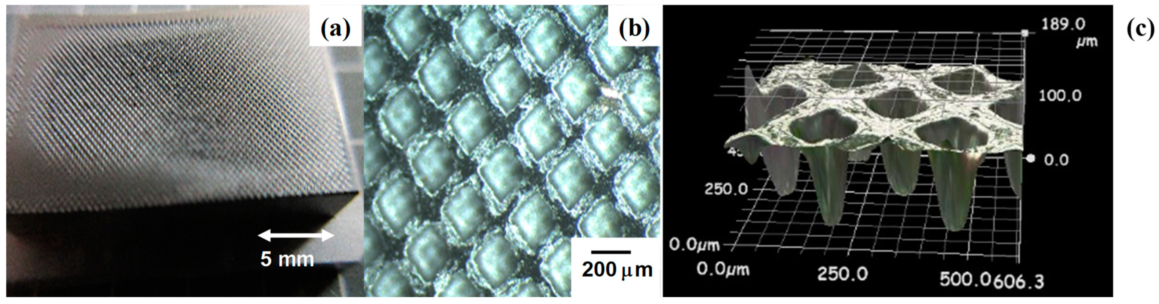
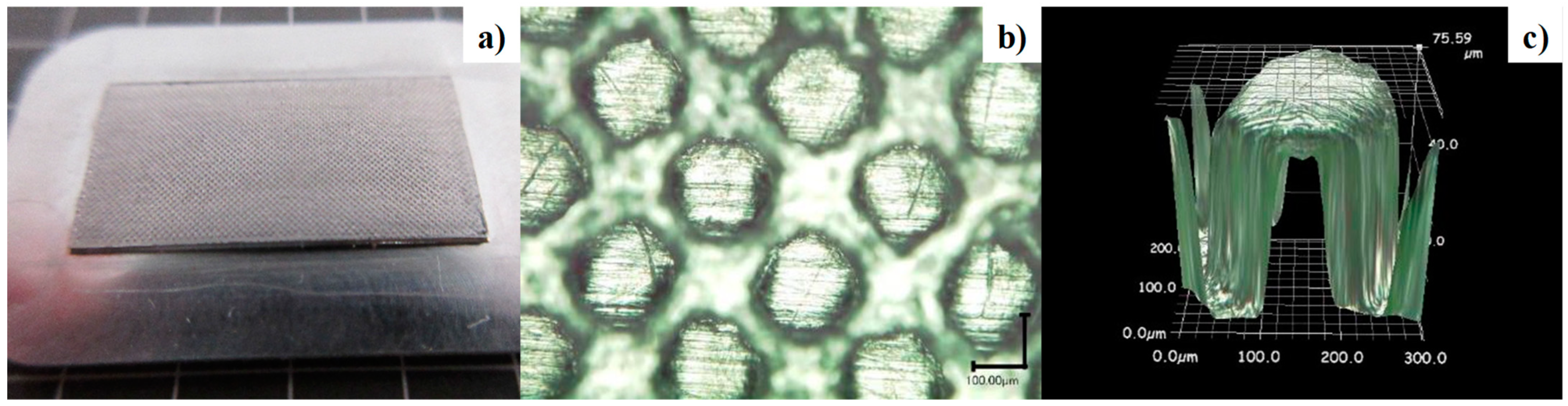
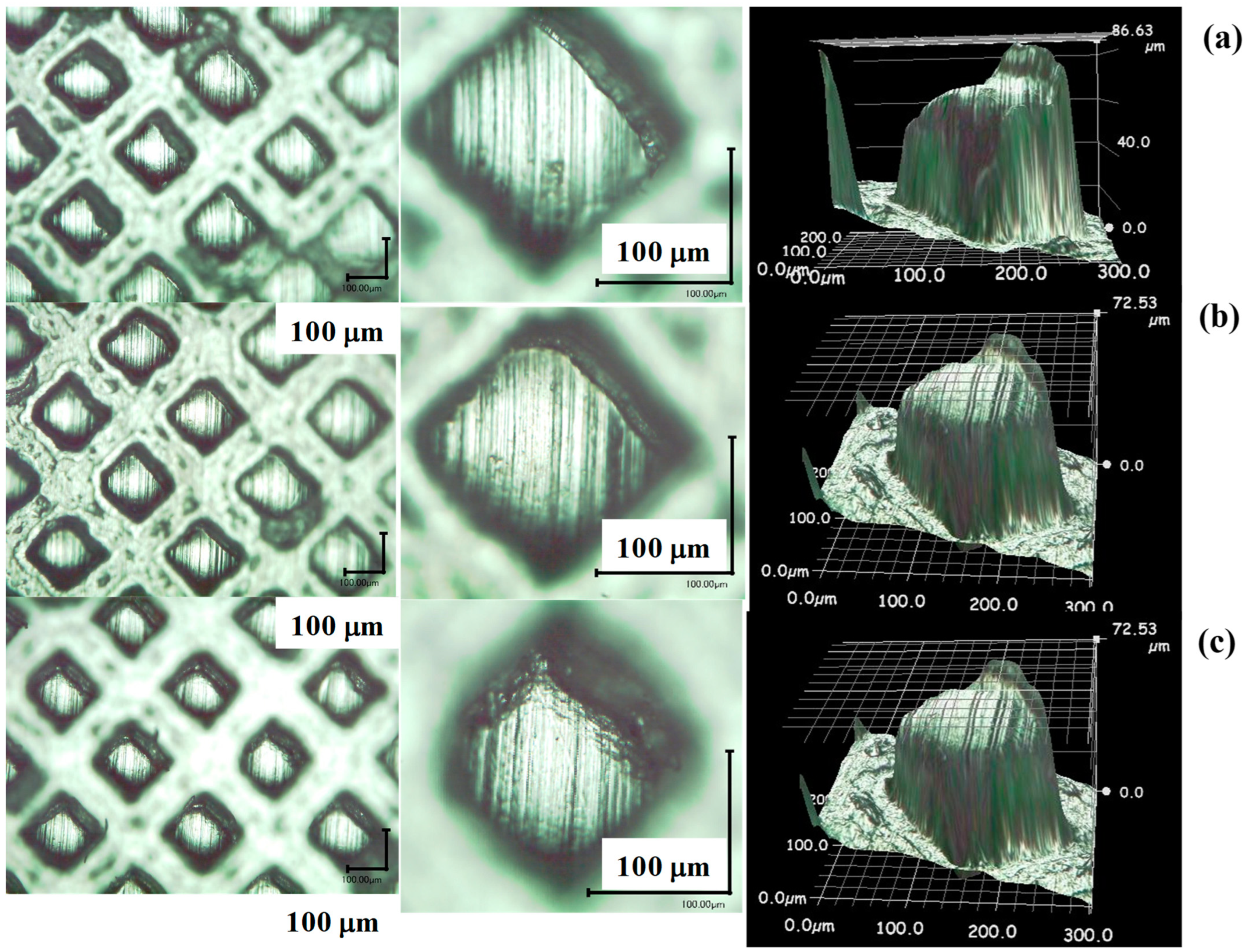
3.6. Warm and Hot Stamping of PIG Die-Cast Preform to Micro-Pillared Heatsink

The PIG die-cast aluminum and aluminum alloy preforms are subjected to forging, blanking and shaping by using the hot stamping unit. This metal forming unit works well to make fine shaping and finishing of preform surfaces. As stated in [22], the temperature control is essential in the hot stamping to improve the dimensional accuracy of products. In the present system, the thermocouple was embedded into the lower cassette die to monitor the thermal transients through every step. In the following experiment, the warm and hot stamping experiments were performed at the specified holding temperature (TH). A PIG die-cast pure aluminum plate was used as a specimen to make microtexturing onto its surface.
Various developments have been reported in the literature on the pure aluminum heatsink with the tailored microtextures to each heat-transferring application [23]. In this study, a micro-pillared pure aluminum heatsink is fabricated by hot stamping with the use of mesh-textured AISI316 punch. Figure 14a depicts the micro-pillared pure aluminum heatsink, warm stamped at 323 K. The pure aluminum work was backward extruded into the micro-cavity array on the AISI316 punch. As depicted in Figure 14b,c, the micro-pillars with the root size of 200 μm × 200 μm and the height of 76 μm are shaped in regular alignment on the heatsink. The depth of micro-cavity in the AISI316 punch is 190 μm in Figure 6c; the extruded height of work is still less than the micro-cavity depth.
The holding temperature was varied to be TH = 373 K, 473 K and 573 K, respectively, in the hot stamping with reference to the monitored lower die temperature. As depicted in Figure 15, the extruded micro-pillar heights (H) at 373 K and 473 K, were nearly the as 76 μm at 323K; e.g., H = 86 μm at 373 K, and H = 73 μm at 473 K. On the other hand, the plastic flow in the backward extrusion was enhanced at 573 K. The extruded micro-pillar height reached 110 μm. This reveals that hot stamping under TH > 573 K enables to make fulfilling of pure aluminum work into the micro-cavity array on the AISI316 punch and to yield the micro-pillared heatsink with relatively high aspect ratio.

4. Discussion

In the sustainable manufacturing, the weight of parts and tools is reduced by exchanging the steels and other structural materials with the aluminum and aluminium alloys. In parallel with this light-weight structuring, the stiffness of aluminium alloy parts must be improved by the tailored thin-walled structure design. Among several structuring designs, the rib-structuring method was highlighted in recent years [24,25]. The rib works as a reinforcing member to increase the bending and torsional rigidities as additive structures to the aluminum alloy plate [24]. As stated in [25], the rib, which is structured against the bending and torsional directions, works well to improve the rigidities. Let us evaluate on the rigidities of PID-die cast gear teeth and curved case through the X-ray tomography. As seen in Figure 12b, the gear tooth surfaces were formed in rigid against the rotational direction. In Figure 13b, the curved surface of A5052 case was shaped to have uniform thickness of 0.5 mm and its corner was formed to be a smooth panel. These prove that various rib-structures are directly shaped into the small-sized and thin-walled products by using the PIG die-casting.
As reported in [26], the effect of holding temperature on the flow stress of aluminum works plays a role to determine the hot stamping schedule. In the hot stamping process for microtexturing onto the cast aluminum plate, the pure aluminum work is difficult to fully fill the micro-cavity array on the AISI316 punch when TH < 573 K. As shown in Figure 11, the excluded micro-pillar has top width of 100 μm and height of 111 μm, and, the distancing space between two adjacent micro-pillars becomes 80 μm at TH = 573 K. This reveals that a micro-pillared pure aluminum heatsink is yielded to have high-aspect-ratio micro-fins with the similar profiles of micro-cavities on the textured punch by using the hot stamping at TH ~ 600 to 650 K.
In the normal die-casting operation, the aluminum alloy preform was shaped by the die casting, and the completely solidified cold preform was pressed to punch out the sprues, the runners or the bosses, and to get out the final preform before finishing and polishing. In the present system, the PIG die-casting unit is linked with the hot stamping unit by rotating the lower die-set on the flat bed. The precise shaping and finishing is performed to fabricate the net-shaped products with less electric energy consuming. The high holding temperature of cast preforms is utilized in the hot stamping; its low flow stress and high deformability results in net-shaping of products. In case of shaping the micro-pillared heatsink, the micro-pillar height increases monotonously with holding temperature in Figure 15. The hot stamping pf PIG-die cast preforms is useful to reduce the energy consumption and to make nee-shaping of aluminum heatsink.
The degassing and solid lubrication played a keyword in the conventional die-casting. In the present PIG-die casting, the nitrogen gas blowing was performed before casting to minimize the contamination of residual air in the cast products. As proved in the non-destructive diagnosis by the X-ray tomography, no residuals and defects were detected to demonstrate the effectiveness of the present degassing procedure. An evacuation process before PIG-die casting might be necessary to further improve the quality of miniature aluminum alloy products in mass production.
The nitrogen supersaturation process was mainly utilized for protection of the PIG-nozzle and die surfaces from the adhesion of aluminum remelts in the PIG-die casting and hot stamping. TiAlN coating onto the nitrided PIG-nozzle also wrought well to protect the PIG-nozzle inner surfaces from severe adhesion of aluminum melts even after successive PIG-die casting processes. This high performance first comes from less chemical compatibility between the aluminum and the bound/unbound nitrogen in the die. As listed and suggested in [27], the supersaturated nitrogen solutes in the nitrided layer as well as the bound nitrogen in TiAlN have excellent chemical resistance to aluminum melts. In addition, after [28,29,30], the present PVD coated TiAlN has high oxidation toughness never to be eroded by pure aluminum and aluminum alloy melts during the PIG die casting. In this manufacturing of aluminum and aluminum alloy parts and members, the nitrogen super-saturation process and TiAlN coating are recommended as an effective surface treatment for galling-free die-casting and hot stamping.

5. Conclusions

A new aluminum manufacturing was proposed to link the PIG die casting unit with warm and hot stamping process for net-shaping of aluminum and aluminum alloy parts and devices. The PIG die-cast preform was stamped at the specified holding temperature to make full use of its low flow stress and to make net-shaping of the product. The small-sized parts and thin-walled members were directly fabricated by the PIG die-casting. The PIG die-cast case thickness reached 0.5 mm together with rib-structuring for reinforcement of aluminum alloy parts and members. Their dimensional accuracy is more improved by warm and hot stamping as a finishing step. In the present study, this new manufacturing process was performed only in two steps. The PIG die-casting process plays the primary step to yield the preform, and, the warm/hot stamping plays the secondary step to fabricate the near-net shaped product. Various manufacturing process with several steps can be designed and performed by exchanging the upper die-sets in each step. To be noticed, the nitrogen supersaturation and TiAlN coating protect the PIG-nozzle, casting and stamping dies from severe chemical attacking of aluminum melts without galling in successive usages.
A micro-pillared pure aluminum heat sink was fabricated by this manufacturing system. Higher aspect ratio of micro-pillar height to root width is attained by hot stamping. Due to the tailored alignment in CAD of micro-pillar textures, the distancing space among the aligned micro-pillars works as a coolant channel to increase the heat penetration factor without increase of the pressure drop in cooling. The nitrogen supersaturated punch was useful for anti-galling hot stamping of aluminum preforms.
Toward the sustainable manufacturing in the carbon neutral society, the expecting forming system of aluminum and aluminum alloys has to stand on the upward recycling procedure of used materials. The present manufacturing process has a capacity to utilize the used aluminum alloy fragments as a feedstock for casting into preform and net-shaping into products without significant loss of work materials and electric power.

Author Contributions

Conceptualization, T.A.; methodology, T.A.; software, T.A. and T.K.; validation, T.A., T.K. and H.S.; formal analysis, T.A.; investigation, T.A., T.K. and H.S.; resources, H.S.; data curation, T.A. and T.K.; writing—original draft preparation, T.A.; writing—review and editing, T.K.; supervision, T.A. and H.S.; project administration, H.S. All authors have read and agreed to the published version of the manuscript.

Funding

This research was funded by METI-program on the Supporting Industry Project, Kanto-Division, METI with the contract number of #18062375 (31 March 2021).

Data Availability Statement

Not applicable.

Acknowledgments

Authors would like to express their gratitude to S-I. Kurozumi (Nano Film Coat, llc.) and the late T. Yamaguchi (Sanko Light Kogyo, Co., Ltd.) for their help in experiment.

Conflicts of Interest

The authors declare no conflict of interest.

References

  1. Edwards, N. With green aluminum flowing, manufactures struggle to make product ESG top priority. Forbes, 22 July 2020. [Google Scholar]
  2. Aizawa, T.; Luangvaranunt, T.; Kondoh, K. Solid state recycling from green wastes to aluminum alloys with high material efficiency. J. JIM 2001, 65, 581–588. [Google Scholar]
  3. Jeong, M.-S.; Lee, S.-Y.; Lee, I.-K.; Lee, S.-K.; Kim, D.; Cho, Y.-J.; Ko, D.-C. Green alternative aluminum extrusion process through process convergence. Int. J. Prec. Eng. Manuf. 2014, 15, 1173–1177. [Google Scholar] [CrossRef]
  4. Hartlieb, M.; Anderson, K. Die casting. 2A. In Aluminum Science and Technology; ASM International: Almere, The Netherlands, 2018. [Google Scholar]
  5. Aizawa, T.; Yamaguchi, T.; Sakayori, H. JP-Patent 2019 with P19HS-001, 31 December 2019.
  6. Aizawa, T.; Yamaguchi, T.; Sakayori, H. Die Casting System and Manufacturing Procedure of Die Cast Products. JP-Patent 2021 with P21SL-001, 31 December 2021. [Google Scholar]
  7. Aizawa, T.; Yamaguchi, T.; Sakayori, H. Metal Forming System and Production Procedure. JP-Patent 2021 with P21SL-002, 31 December 2021. [Google Scholar]
  8. Aizawa, T.; Kurihara, T.; Yamaguchi, T.; Sakayori, H. Near-net shaping of aluminum alloy parts by pin-injection-gate die-casting. In Proceedings of the 13th AWMFT, Shanghai, China, 6 December 2021; pp. 253–262. [Google Scholar]
  9. Funazuka, T.; Dohda, K.; Takatsuji, N.; Hu, C.; Ngernbamrung, S. Effect of die coating on surface crack depth of hot extruded 7075 aluminum alloy. Friction 2022, 143, 21–32. [Google Scholar] [CrossRef]
  10. Aizawa, T. Low Temperature Plasma Nitriding of Austenitic Stainless Steels. Chapter 3 in Stainless Steels and Alloys; IntechOpen: London, UK, 2019; pp. 31–50. [Google Scholar]
  11. Aizawa, T.; Dohda, K.; Shiratori, T. Nano-structured tribo-coating for cold and hot stamping. In Proceedings of the 52nd ICFG Plenay Meeting, San Sebastian, Spain, 16 September 2019; pp. 116–123. [Google Scholar]
  12. Shiratori, T.; Aizawa, T.; Saito, Y.; Dohda, K. Fabrication of micro-punch array by plasma printing for micro-embossing into copper substrates. Materials 2019, 12, 2640. [Google Scholar] [CrossRef] [PubMed] [Green Version]
  13. Shiratori, T.; Aizawa, T.; Saito, Y.; Wasa, K. Plasma printing of an AISI316 micro-meshing punch array for micro-embossing onto copper plates. Metals 2019, 9, 396. [Google Scholar] [CrossRef] [Green Version]
  14. Borgioli, F.; Galvanetto, E.; Bacco, T. Low temperature nitriding of AISI300 and 200 series austenitic stainless steels. Vacuum 2016, 12, 51–60. [Google Scholar] [CrossRef]
  15. Domain, C.; Becquart, C.S.; Foct, J. Ab initio study of foreign interstitial atom (C, N) interactions with intrinsic point defects in α-Fe. Phys. Rev. B 2004, 69, 144122. [Google Scholar] [CrossRef]
  16. ECO, Aluminum Die Casting. Available online: https://www.ecodiecasting.com/aluminum-die-casting/ (accessed on 3 June 2022).
  17. Xie, Z.; Jiao, J.; Yang, K. Theoretical and experimental study on the fluid-structure—Acoustic coupling dynamics of a new water lubricated bearing. Tribol. Int. 2023, 177, 107982. [Google Scholar] [CrossRef]
  18. Cleary, P.W.; Ha, J.; Prkash, M.; Nguyen, T. Short shots and industrial case studies: Understanding fluid flow and solidification in high pressure die casting. Appl. Math. Model. 2010, 34, 2018–2033. [Google Scholar] [CrossRef] [Green Version]
  19. Seow, L.W.; Lm, Y.C. Optimizing flow in plastic injection molding. J. Mater. Process. Technol. 1997, 72, 333–341. [Google Scholar] [CrossRef]
  20. JST, Aluminum Alloy Gear. Available online: http://www.precise-gear.com/aluminum-alloy-gear.html (accessed on 3 June 2022).
  21. Gangopadhyay, S.; Acharya, R.; Chattopadhyay, A.K.; Sargade, V.G. Effect of cutting speed and surface chemistry of cutting tools on the formation of bul or bue and surface quality of the generated surface in dry turning of AA6005 aluminum alloy. Mach. Sci. Technol. 2010, 14, 208–223. [Google Scholar] [CrossRef]
  22. Maeno, T.; Mori, K.-I.; Yachi, R. Hot stamping of high-strength aluminum alloy aircraft parts using quick heating. CIRP Ann. 2017, 66, 269–272. [Google Scholar] [CrossRef]
  23. Kumaraguruparan, G.; Sornakumar, T. Development of testing of aluminum micro channel heat sink. J. Therm. Sci. 2010, 19, 245–252. [Google Scholar] [CrossRef]
  24. Gong, M.F.; Li, Z.; Dong, J. Mechanics analysis of reinforcing rib structure in aluminum heating-plate automatic casting system. Adv. Mater. Res. 2012, 538–541, 1755–1761. [Google Scholar] [CrossRef]
  25. Ohashi, T.; Tabetabei, H.M.; Nishimura, T. Rib-structure on A5083 aluminum alloy sheet generated friction stir forming. Preced. Eng. 2017, 207, 1153–1158. [Google Scholar] [CrossRef]
  26. Ma, Z.; Ji, H.; Huang, X.; Xiao, W.; Tang, X. Research on high temperature stamping forming performance and process parameters optimization of 7075 aluminum alloy. Materials 2021, 14, 5435. [Google Scholar] [CrossRef]
  27. Chemical Resistance Reference Chart. Available online: https://www.calpaclab.com/content/chemical-charts/Aluminum.pdf (accessed on 6 November 2022).
  28. Kumar, S.; Maity, S.R.; Patnaik, L. Friction and tribological behavior of bare nitrided, TiAlN and AlCrN coated MDC-K hot work tool steel. Ceram. Int. 2020, 46, 17280–17294. [Google Scholar] [CrossRef]
  29. Tollmann, W.; Grisales, D.; Stangier, D.; Butzke, T. Tribomechanical behavior of TiAlN and CrAlN coatings deposited onto AISI H11 with different pre-treatments. Coatings 2019, 9, 519. [Google Scholar] [CrossRef]
  30. Dohda, K.; Aizawa, T.; Funazuka, T. Process tribology of PVD nitride coated dies in hot metal forming. Friction, 2022; in press. [Google Scholar]
Figure 1. Two procedures to yield the aluminum products. (a) PIG die-casting procedure, and (b) Combined process of PIG die casting and hot stamping.
Lubricants 11 00013 g001
Figure 2. Manufacturing system including the PIG die-casting and hot stamping unit. (a) Overview of the total system, and (b) rotating bed to exchange the die set.
Lubricants 11 00013 g002
Figure 3. PIG-nozzle unit including the weight-measuring section, the plunger, the pressurizing tools, and the heating section. (a) Schematic view of PIG-nozzle unit, and (b) overview of PIG-nozzle unit.
Lubricants 11 00013 g003
Figure 4. A low temperature plasma nitriding system. (a) Its schematic view, and (b) its overview with 1: vacuum chamber, 2: RF-generator, 3: control panel, 4: RF/DC controller, 5: evacuation unit, and 6: gas flow units.
Lubricants 11 00013 g004
Figure 5. A plasma printing procedure with aid of the low temperature plasma nitriding. (a) CAD design on the mesh-patterned punch head, (b) a unit cell of mesh-pattern, (c) a unit cell on the screen-film for screen printing, (d) a nitrided unit cell of microtextures on the die surface at 673 K for 14.4 ks, and (e) a unit cell of mesh-patterned die after sand-blasting.
Lubricants 11 00013 g005
Figure 6. The mesh-textured AISI316 punch by the plasma printing. (a) Overview of textured punch, (b) SEM image on the punch surface, and (c) three dimensional profile of microtextures.
Lubricants 11 00013 g006
Figure 7. Nitrogen solute content and hardness depth profiles in the nitrided AISI20J2 materials for PIG-nozzles and dies. (a) Nitrogen solute depth profile measured by SEM-EDX, and (b) hardness depth profile measured by micro-Vickers hardness testing.
Lubricants 11 00013 g007
Figure 8. Comparison of the corrosion and erosion toughness between the un-nitrided and nitrided AISI420J2 surfaces. (a) Chemically etched specimen with un-nitrided zones (A) and nitrided zones (B), and (b) border between un-nitrided zone (A) and nitrided zone (B).
Lubricants 11 00013 g008
Figure 9. Distribution of chromium and nitrogen contents on the dipped AISI420J2 surfaces from “A” to “B” across “X”.
Lubricants 11 00013 g009
Figure 10. Dynamic behavior in the free injection of the aluminum melt from the PIG-nozzle outlet gate. Every snapshot was retrieved and selected from the vide frame images.
Lubricants 11 00013 g010
Figure 11. A short-shot experiment by using the double PIG-nozzle units for PIG die-casting. (a) Aluminum melt flow into the rectangular die cavity, (b) solidified aluminum melts.
Lubricants 11 00013 g011
Figure 12. PIG die-cast, small-sized gear block by using a single PIG-nozzle unit. (a) The cast and solidified pure aluminum gear block, and (b) X-ray tomographic image of gear block.
Lubricants 11 00013 g012
Figure 13. PIG die-cast, thin-walled AA5052 mobile phone case by using the double PIG-nozzle units. (a) The cast and solidified AA5052 mobile phone case, and (b) X-ray tomographic images of case.
Lubricants 11 00013 g013
Figure 14. Warm stamping of pure aluminum solidified preform for microtexturing its surface. (a) Warm stamped pure aluminum heatsink at 323 K, (b) alignment of micro-pillars formed by warm stamping, and (c) three dimensional profile of a micro-pillar shaped onto the aluminum preform.
Lubricants 11 00013 g014
Figure 15. Effect of the holding temperature during the hot stamping on the microtexture formation. (a) Micro-pillar array, top surface of extruded micro-pillar, and its three dimensional profile at 373 K, (b) at 473 K, and (c) at 573 K.
Lubricants 11 00013 g015
Disclaimer/Publisher’s Note: The statements, opinions and data contained in all publications are solely those of the individual author(s) and contributor(s) and not of MDPI and/or the editor(s). MDPI and/or the editor(s) disclaim responsibility for any injury to people or property resulting from any ideas, methods, instructions or products referred to in the content.

