Article

The Effects of Interval Uncertainties on Dynamic Characteristics of a Rotor System Supported by Oil-Film Bearings

1
School of Mechatronics Engineering, Foshan University, Foshan 528000, China
2
Institute of Structural Strength and Design of Intelligent Aircraft, Northwestern Polytechnical University, Xi’an 710072, China
3
Science and Technology on Thermal Energy and Power Laboratory, Wuhan Second Ship Design and Research Institute, Wuhan 430205, China
*
Authors to whom correspondence should be addressed.
Lubricants 2022, 10(12), 354; https://doi.org/10.3390/lubricants10120354
Submission received: 18 November 2022 / Revised: 4 December 2022 / Accepted: 7 December 2022 / Published: 8 December 2022

Abstract

:
Rotating systems equipped with oil-film bearings are critical and common in many industrial machines. There are various non-random uncertainties in such fluid-lubricated dynamic systems. It is important to quantify the effects of uncertainties without adequate statistical information on the dynamics of rotor-bearing systems. In this paper, a rotor system with oil-film bearings at both ends is investigated considering many interval uncertainties. The rotating system is modeled in a deterministic sense. The Chebyshev interval method is used to track the propagation of different uncertainties. Deviations in the steady state responses, time history, and shaft orbits are calculated and comparatively discussed. Influence patterns of different interval parameters and dispersions in various dynamics are presented in detail. It is found that there can be global and local impacts as well as cumulative effects caused by multi-source uncertainties. The findings of the present study could be helpful for a more insightful dynamic analysis of rotor-bearing systems as well as their optimal design and maintenance.

1. Introduction

Rotor systems supported by oil-film bearings are very common in engineering, such as turbochargers [1] and pumps [2]. The lubricants can separate the rotor shaft and bearings to reduce the friction and wear of critical components. Moreover, the fluid-lubricated bearings are recognized to have a large load-carrying capacity, which is beneficial to large-sized heavy-duty machinery. Although many variants, such as tilting pad journal bearings [3], are available in modern industry, the lubrication characteristics of plain oil-film bearings and the corresponding rotordynamics are still the core research interests of many investigators [4,5,6]. It has been identified that uncertain factors in rotor systems supported by oil-film bearings play crucial roles in design and dynamic studies [7,8,9,10,11,12].
Indeed, there are many ubiquitous uncertainties in an engineering fluid film-lubricated bearing rotor system [13]. The manufacturing of mechanical components can introduce errors, affecting their geometrical and material properties. Tolerances are allowed when the system is assembled, which causes clearance and concentricity variations. The viscosity of lubricants largely depends on the temperature. However, as the machine runs, the fluctuations in temperature are inevitable and extremely difficult to predict [14]. Even if the temperature is recorded continuously, it is generally impossible to incorporate it precisely in the early-stage design or dynamic assessment. The above fact requires that any irreducible uncertainty in a rotor-bearing system should be properly dynamically analysed to be robust or even valid. Up till now, many researchers have made their contributions to clarify the evolution of lubrication characteristics of oil-film bearings and dynamics of rotating systems with mandatory uncertainties included [15,16,17,18,19]. For example, Sun et al. [20] investigated the stability of a journal bearing rotor based on an analytical model considering misalignment and parametric uncertainty. Garoli and Castro [21] studied the fluid-induced instability and responses of a rotor system model considering bearing stochasticity. Geng et al. [22] proposed a double integral method to quantify the impact introduced by bearing uncertainties in the responses of a thin-walled casing. A simple derivative-based method was proposed by Medina et al. [23] for the prediction of bearing rotor dynamic coefficients, i.e., stiffness and damping coefficients. Sensitivity indices of uncertainties were calculated, and the obtained results were compared with experimental tests. Rough surfaces in bearings are another important uncertain quantity, which were comparatively studied by Tauviqirrahman et al. [24]. A heterogeneously patterned rough surface in a journal bearing was employed, and the acoustic and tribological performances were discussed. Da Silva and Nicoletti [25] studied the effects of uncertainty in the bearing clearance on journal bearing reliability. Li et al. [26] investigated the nonlinear dynamics, including the bifurcations, shaft orbits, and responses, of a rotor model including the random fluid forces. Intelligent data-driven methods, such as the deep convolutional neural network [27], have been used to include uncertainties for rotor-bearing system fault identifications. These works all adopted stochastic models of the uncertainties and assumed their probabilistic distributions, such as the polynomial chaos expansion. This prerequisite can be subjective, leading to possible unreliable results. The selection and establishment of the uncertainty models should rely on available information [28]. Probabilistic models can be rigorous, and the obtained results are profound. However, they do not suit the case where little prior statistical data exists [29]. Although the fuzzy-type method is helpful and will alleviate the hash requirement to some extent, the membership functions in it can be hard to determine. Thus, the interval-based uncertainty quantification methods [30] are proposed for dynamic problems with limited information. In such interval models, the descriptions of uncertain parameters are simple, and only the bounds are required [31]. Thus, the interval models for uncertainties will be particularly suitable for variables with sparse information, which is more common in the complex engineering context, since the strict and mandatory requirements in the probabilistic and fuzzy algorithms are removed. Consequently, the obtained results are essentially interval quantities. Ma et al. [32] applied an intrusive interval procedure to a rotor system for dynamic response predictions. Fu et al. [33] constructed the surrogate function for the rubbing dual-rotor system based on the polynomial series. It is found that the non-intrusive methods have great convenience in solving complex linear and nonlinear uncertain vibration problems without modifications to the deterministic solvers. This feature will facilitate applications of them to a variety of scenarios without limitations, i.e., they are adaptive to different problems.
From the literature review, previous studies mostly focused on the stochastic analysis of rotor-bearing systems. There is little research on the interval uncertain dynamics of rotor systems with oil-film bearings, which are more common in reality. Moreover, it is mandatory to explore the effectiveness of interval methods for the non-probabilistic dynamics computation of such systems. This paper aims to discard the hypothesis made in previous stochastic studies and cope with a more generalized scenario. The comprehensive interval dynamic responses of the rotor-bearing system, including the interval orbits, time history, and steady state responses will be investigated. Cases considering many interval physical quantities are studied. The established methods can be adapted to deal with various dynamic problems of such systems without limitations to the current system configuration and dynamic characteristics, which demonstrates excellent versatility.

2. Deterministic Modeling and Solution

A double-disc rotor system supported by oil-film bearings is considered for the present study, as illustrated in Figure 1. In this section, the modeling of the system is detailed according to the finite element analysis and hydrodynamic theory. The modal property and response solution of the established dynamic model are presented as well, which serves as the deterministic basis for the consequent interval uncertainty analysis.

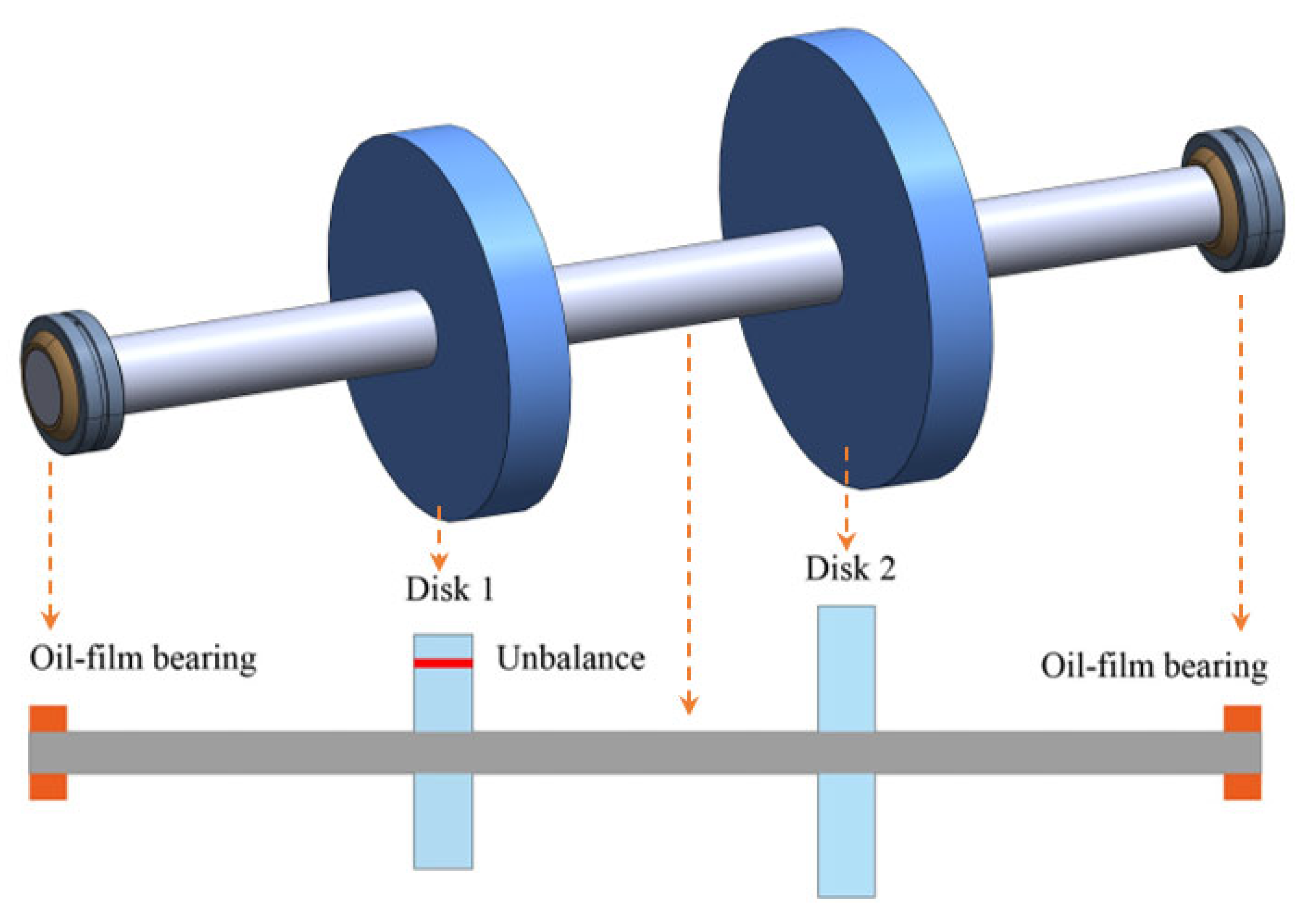
2.1. Finite Element Modeling of Rotor

The finite element modeling of the rotor includes the modeling of disc elements, shaft elements, and bearing supports. Accurate modeling of these elements is important for a meaningful dynamic analysis. For example, researchers have made many efforts [34,35] in the modeling of details of various elements including connections, supports, and dampers. Modeling of shaft and disc elements is described in this subsection. The bearing element will be described in the next subsection. According to the finite element theory applied in rotordynamics [36], a disk element has the following kinetic energy
T d = 1 2 m d ( x ˙ d 2 + y ˙ d 2 ) + 1 2 I d ( φ ˙ d 2 + β ˙ d 2 ) + 1 2 I p ( ω 2 2 ω β ˙ d φ d ) ,
where md is the mass of a disk, Id and Ip denote the diameter and polar moments of inertia, xd represents the displacement along the x direction, yd denotes the displacement along the y direction, ω is the angular rotation speed, and φ d and β d are the rotation angles along the two perpendicular axes. Thus, according to the Lagrange formulation, the following terms can be derived
[ d d t ( T d x ˙ d ) T d x d d d t ( T d β ˙ ) T d β ] = [ m d m d I d I d ] [ x ¨ d y ¨ d φ ¨ d β ¨ d ] + ω [ I p I p ] [ x ˙ d y ˙ d φ ˙ d β ˙ d ] .
In the above equation, the elemental mass and gyroscopic matrices are presented.
For a shaft element there is an additional elemental stiffness matrix apart from the mass and gyroscopic matrices. The deflection within a beam element can be fitted by using the shape functions as
u e ( ξ ,   t ) = [ N 1 ( ξ )   N 2 ( ξ )   N 3 ( ξ )   N 4 ( ξ ) ] [ x 1   ϕ 1   x 2   ϕ 2 ] T ,
where ξ characterizes a position variable, [ N 1 ( ξ )   N 2 ( ξ )   N 3 ( ξ )   N 4 ( ξ ) ] are the shape function set, and [ x 1   ϕ 1   x 2   ϕ 2 ] represents the lateral displacement set in the x direction. The strain energy of the Euler beam element in one lateral direction can be expressed as
U e = 1 2 0 l e E e I e ( ξ ) ( 2 u e ( ξ ,   t ) ξ 2 ) 2 d ξ ,
where le is the beam element length, Ee is the elastic modulus, and Ie = πr4/4 is the moment of area of the shaft cross-section with r being the radius of the rotor shaft. The kinetic energy of the shaft element can be defined as
T e = 1 2 0 l e ρ e A e ( ξ ) u ˙ e 2 ( ξ ,   t ) d ξ ,
where ρ e is the material density and A e is the area of the shaft cross-section. Based on the Lagrange equation, the elemental matrices of a shaft element can be calculated. Since the two bending planes corresponding to the lateral motions are not coupled, the full expressions of the shaft elemental matrices are [36]
M e = ρ e A e l e 420 [ 156 0 0 22 l e 54 0 0 13 l e 0 156 22 l e 0 0 54 13 l e 0 0 22 l e 4 l e 2 0 0 13 l e 3 l e 2 0 22 l e 0 0 4 l e 2 13 l e 0 0 3 l e 2 54 0 0 13 l e 156 0 0 22 l e 0 54 13 l e 0 0 156 22 l e 0 0 13 l e 3 l e 2 0 0 22 l e 4 l e 2 0 13 l e 0 0 3 l e 2 22 l e 0 0 4 l e 2 ] ,
K e = E e I e l e 3 [ 12 0 0 6 l e 12 0 0 6 l e 0 12 6 l e 0 0 12 6 l e 0 0 6 l e 4 l e 2 0 0 6 l e 2 l e 2 0 6 l e 0 0 4 l e 2 6 l e 0 0 2 l e 2 12 0 0 6 l e 12 0 0 6 l e 0 12 6 l e 0 0 12 6 l e 0 0 6 l e 2 l e 2 0 0 6 l e 4 l e 2 0 6 l e 0 0 2 l e 2 6 l e 0 0 4 l e 2 ] ,
G e = ρ e I e 15 l e [ 0 36 3 l e 0 0 36 3 l e 0 36 0 0 3 l e 36 0 0 3 l e 3 l e 0 0 4 l e 2 3 l e 0 0 l e 2 0 3 l e 4 l e 2 0 0 3 l e l e 2 0 0 36 3 l e 0 0 36 3 l e 0 36 0 0 3 l e 36 0 0 3 l e 3 l e 0 0 l e 2 3 l e 0 0 4 l e 2 0 3 l e l e 2 0 0 3 l e 4 l e 2 0 ] .
The rotary and shear effects can be included in the above deductions, which leads to the Timoshenko beam element.

2.2. Oil-Film Bearing Model

Oil-film bearings are a classic hydrodynamic structure [37]. Oil is supplied to the clearance between the journal and bearing and forms a fluid film as the journal rotates, thus separating the direct dry contact surfaces. Assuming the pressure of lubricant equals zero at the bearing ends and the flow can be described as laminar, the Reynolds equation holds for such fluid-lubricated systems. Furthermore, if the length-to-diameter ratio is small the bearing can be referred to as a short bearing. Negative pressure in areas of the clearance is assigned zero. The forces provided by the oil film can be given as [38]
{ F r = D ω υ L b 3 ε 2 2 c ( 1 ε 2 ) 2 F t = π D ω υ L b 3 ε 8 c ( 1 ε 2 ) 3 / 2 ,
where Fr and Ft are the fluid forces along the radial and tangential directions, and D, Lb, c, υ and ε are the diameter, length, clearance, lubricant viscosity, and eccentricity, respectively. The two force components will be exerted on the shaft. The resultant bearing force, Fb (load-carrying capacity), and attitude angle, α b , can be calculated by
F b = π D ω υ L b 3 ε 8 c ( 1 ε 2 ) 2 ( 16 π 2 π 2 ε 2 + 1 ) ,
α b = arctan π 1 ε 2 4 ε .
Normally, the load on a bearing is vertical, such as the weight of shafts and disks. The final magnitude of the bearing resultant force must equal the load and its direction opposite. Thus, the eccentricity and Ocvirk number can be determined based on Equations (10) and (11) depending on the structural configuration and lubricant characteristics of the oil-film bearing, as well as the rotating speed and external loads. Based on the short bearing model, its dynamic characteristics are calculated by [36]
K b = F b c [ π 2 ( 1 ε 2 ) + 16 ε 2 ] 3 / 2 [ k 11 k 12 k 21 k 22 ] ,
C b = F b ω c [ π 2 ( 1 ε 2 ) + 16 ε 2 ] 3 / 2 [ c 11 c 12 c 21 c 22 ] ,
where
k 11 = 4 [ π 2 ( 2 ε 2 ) + 16 ε 2 ] ,
k 12 = π [ π 2 ( 1 ε 2 ) 2 16 ε 4 ] ε 1 ε 2 ,
k 21 = π [ π 2 ( 2 ε 2 ) ( 1 + 2 ε 2 ) + 32 ε 2 ( 1 + ε 2 ) ] ε 1 ε 2 ,
k 22 = 4 [ π 2 ( 1 + 2 ε 2 ) + 32 ε 2 ( 1 + 2 ε 2 ) 1 ε 2 ] ,
c 11 = 2 π 1 ε 2 [ π 2 ( 1 + 2 ε 2 ) 2 16 ε 2 ] ε ,
c 12 = c 21 = 8 [ π 2 ( 1 + 2 ε 2 ) 16 ε 2 ] ,
c 22 = 2 π [ π 2 ( 1 ε 2 ) 2 + 48 ε 4 ] ε 1 ε 2 .
The dynamic coefficients can be integrated into the rotor model directly by establishing the equations of motion.

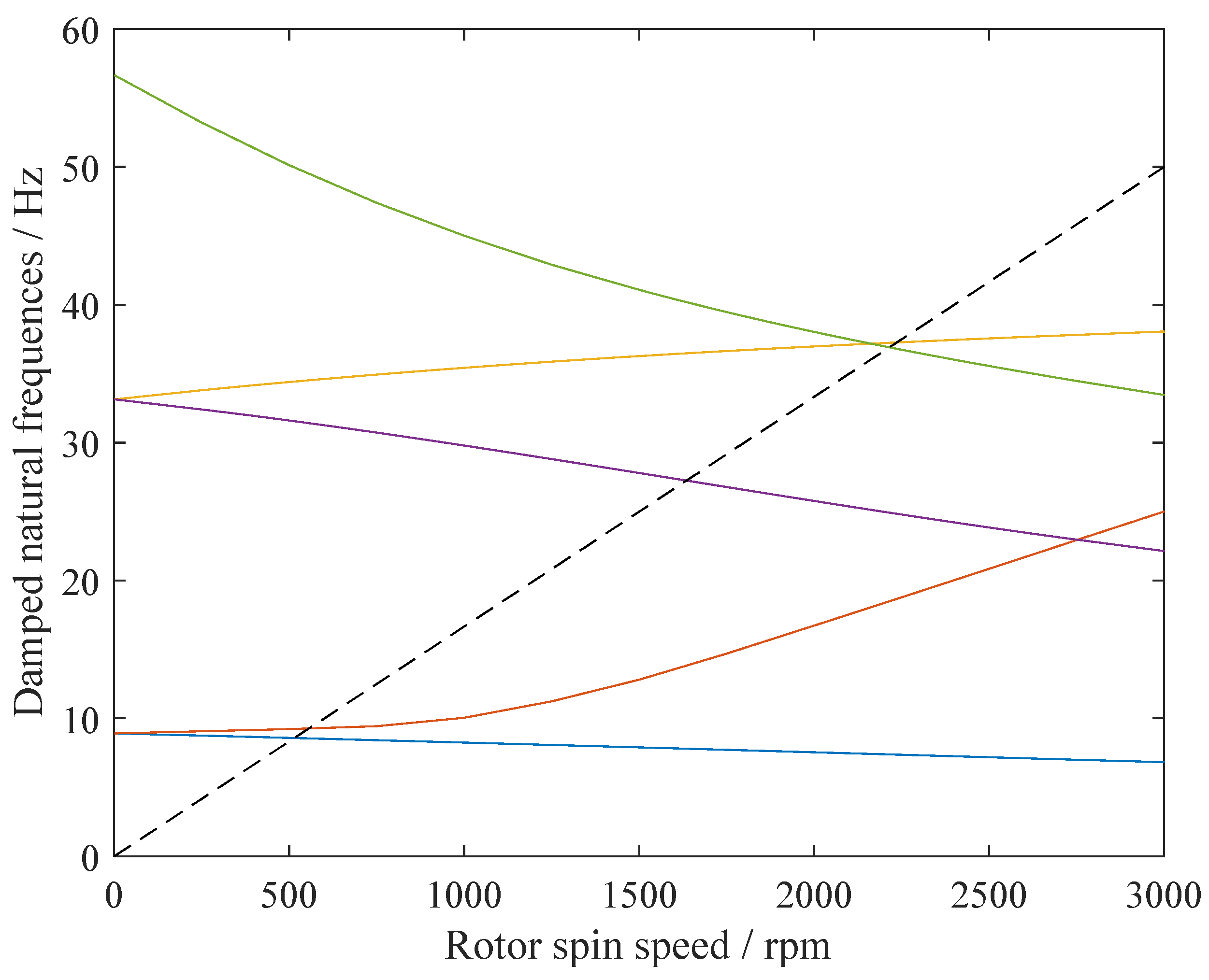
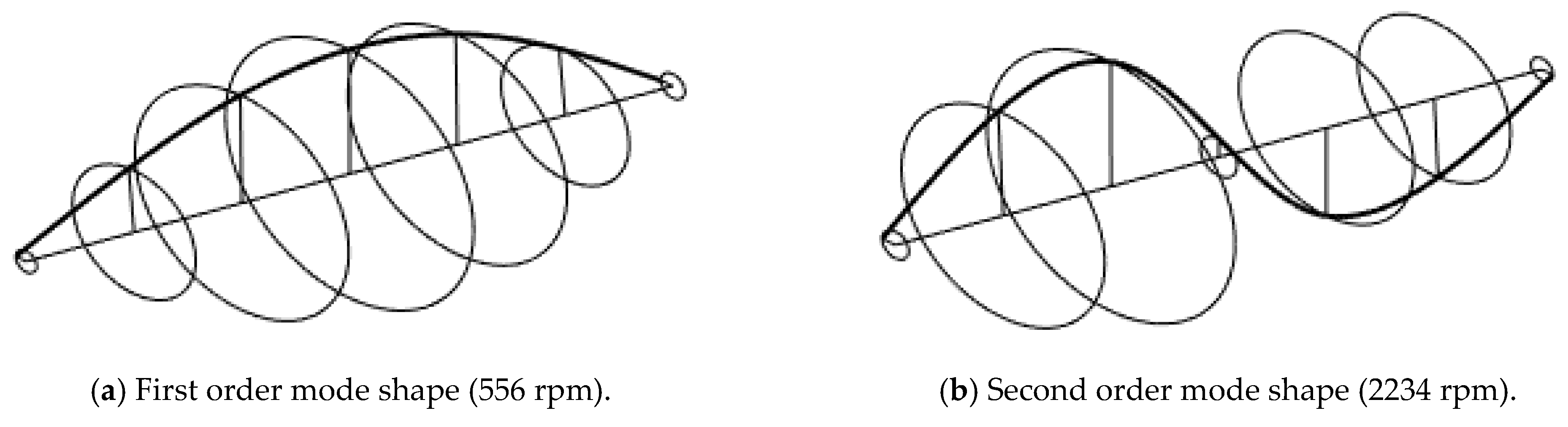
2.3. Dynamic Characteristic Analysis

When all the elements in the system are modeled, its overall governing motion equations can be assembled. When X = [ x 1 ,   y 1 ,   ϕ 1 ,   θ 1 ,   ,   x q ,   y q ,   ϕ q ,   θ q ] T is the full degrees of freedom in the system, the q-node full equation is
M X ¨ + ( C + ω G ) X ˙ + K X = F g + F u ( t ) ,
where M, C, K and G are the mass, damping, stiffness, and gyroscopic matrices, respectively, and Fg and Fu(t) denote the gravitational force and unbalance force vectors, respectively.
The natural characteristics, including critical speeds and their corresponding mode shapes, are obtained from calculating the eigenvalue problem using
{ A Y ˙ + B Y = 0 Y = [ X ;   X ˙ ] ,
where
{ A = [ C + ω G M M 0 ] B = [ K 0 0 M ] .
The dynamical system given in Equation (14) can be solved by the numerical integration schemes. For example, the Newmark-β method. Then, the shaft orbit and time history, as well as steady state responses, can be derived based on the numerical solutions.

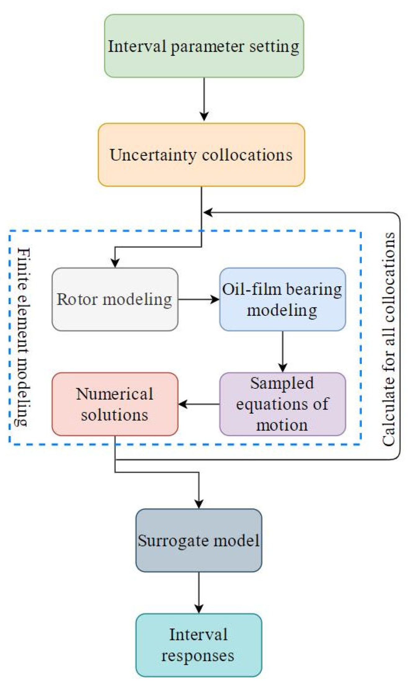
3. Interval Uncertainty Approach

The modeling and solution process detailed in previous sections are based on deterministic formulations, i.e., the parameters and configurations are free of uncertainty. Naturally, it is inadequate if parametric uncertainties are considered. As pointed out in the introduction, non-probabilistic scenarios are more common in the engineering context and the interval-based quantification algorithms have fewer prerequisites regarding the prior distribution properties. The Chebyshev method [30] can track effectively the propagation of non-random uncertainties in mechanical vibration systems and it is non-intrusive. This means that it can be introduced into the dynamical study of the oil-film bearing supported rotor system without additional modifications of the deterministic solvers.
To enable propagation of the input interval uncertainty, a transformation needs to be done in the first place because physical parameters have different magnitude scales. For a physical interval variable
ϑ = arccos 2 a ( a ¯ + a _ ) a ¯ a _ ,
where ϑ [ 0 ,   π ] and a [ a _ ,   a ¯ ] , with a _ and a ¯ being the lower and upper bounds of a. The linear projection links a practical rotor parameter with a standard interval variable, which benefits further surrogate modeling. If more than one interval physical parameter is considered, the above transformation should be done for each one, making it a vectorized calculation. The k-order Chebyshev surrogate for the desired rotor dynamic responses, ϒ , under uncertainty (it can be any interested quantities, such as the time history and steady state solutions) can be given as
ϒ ( ϑ ,   t ) = m 1 = 0 k m r = 0 k 1 2 λ Τ m 1 , , m n C m 1 , , m n ( ϑ ) ,
where λ is the appearance times of zero in subscripts m 1 , , m n , n represents the number of interval parameters considered, Τ m 1 , , m n is the coefficient to be determined, and C m 1 , , m n denotes the multi-dimensional Chebyshev polynomial, which is expressed by
C m 1 , , m n ( θ ) = cos ( m 1 ϑ 1 ) cos ( m 2 ϑ 2 ) cos ( m n ϑ n ) .
The unknown surrogate coefficients are solved by the Mehler integration [30]:
Τ m 1 , , m n = ( 2 π ) n 0 π 0 π ϒ ( cos ϑ 1 , , cos ϑ n ) cos ( m 1 ϑ 1 ) cos ( m n ϑ n ) d ϑ 1 d ϑ n ,
However, the above integration cannot be directed computed due to the implicit relationships between the uncertain dynamic response and uncertainty inputs, i.e., there is no expression of ϒ ( cos ϑ 1 , , cos ϑ n ) . The Gauss quadrature is introduced for a numerical realization of Equation (20):
Τ m 1 , , m n = j 1 = 0 h j n = 0 h ( 2 h ) n ϒ ^ ( t , cos θ j 1 , , cos θ j n ) cos ( m 1 θ j 1 ) cos ( m n θ j n ) ,
where h is the number of collocation points, which should not be less than k + 1 for single interval input, and ϒ ^ ( t , cos θ j 1 , , cos θ j n ) is the sampled response obtained by setting the interval parameter to collocation points. For multi-dimension collocation, they have the following calculation formulas
{ θ j = 2 j 1 2 h π ,   j = 1 ,   2 ,   ,   h θ ˜ = θ j 1 θ j 1 θ j n ,
where represents the tensor product. It can be seen that Equations (21) and (22) associate the Chebyshev surrogate model with the original rotor-bearing system. It is found that a few collocations will facilitate a surrogate capable of giving accurate predictions. After the surrogate coefficients are calculated, the surrogate function is established and the desired uncertain response bounds could be computed by applying a scanning procedure to the simple surrogate model, which imposes neglectable burdens. It is worth mentioning that the whole uncertainty prediction process is non-intrusive, preserving the complex rotor-bearing deterministic solver structure and bringing many conveniences.
The overall analysis procedure of the rotor system with oil-film bearings subject to interval uncertainty is demonstrated in Figure 2.

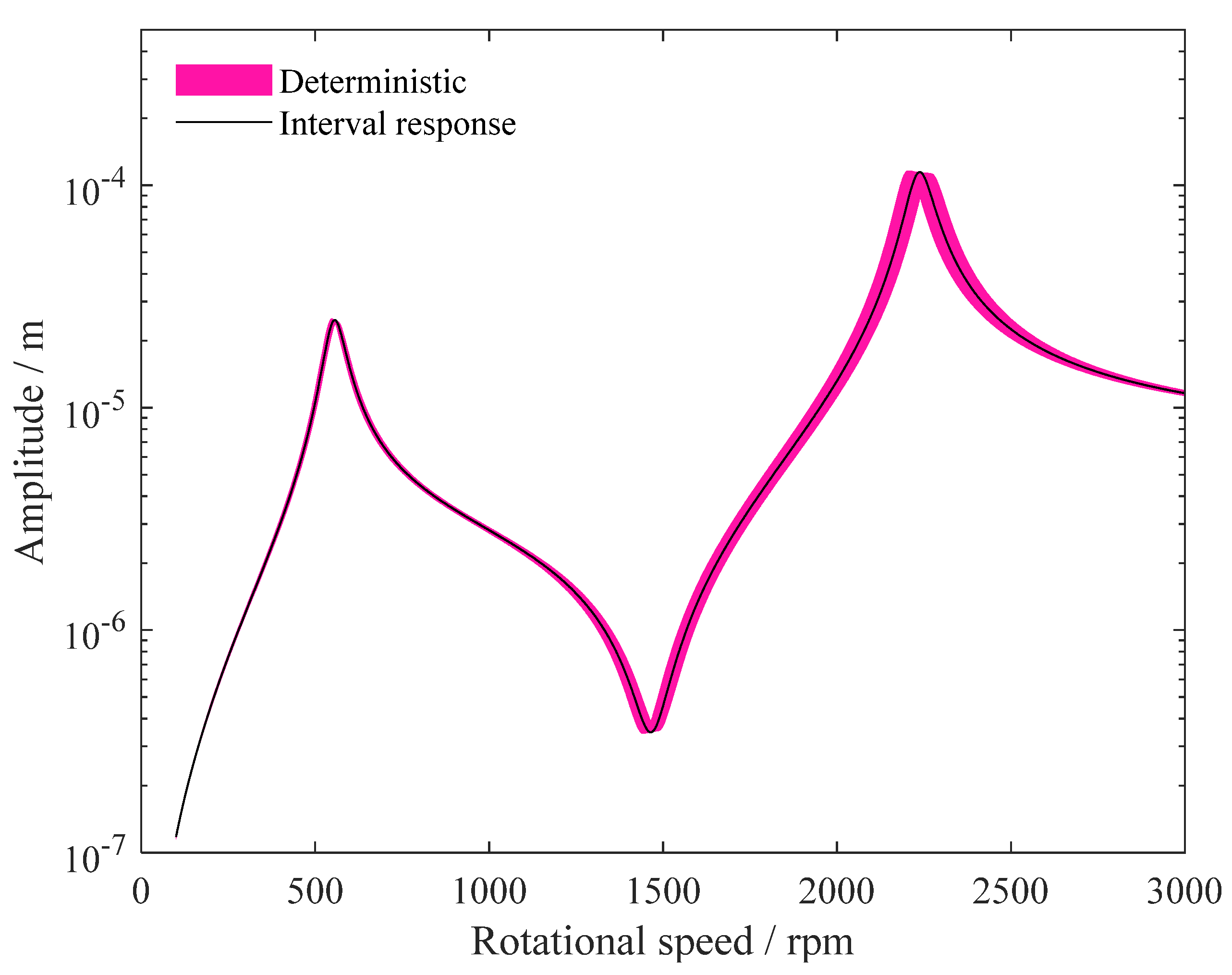
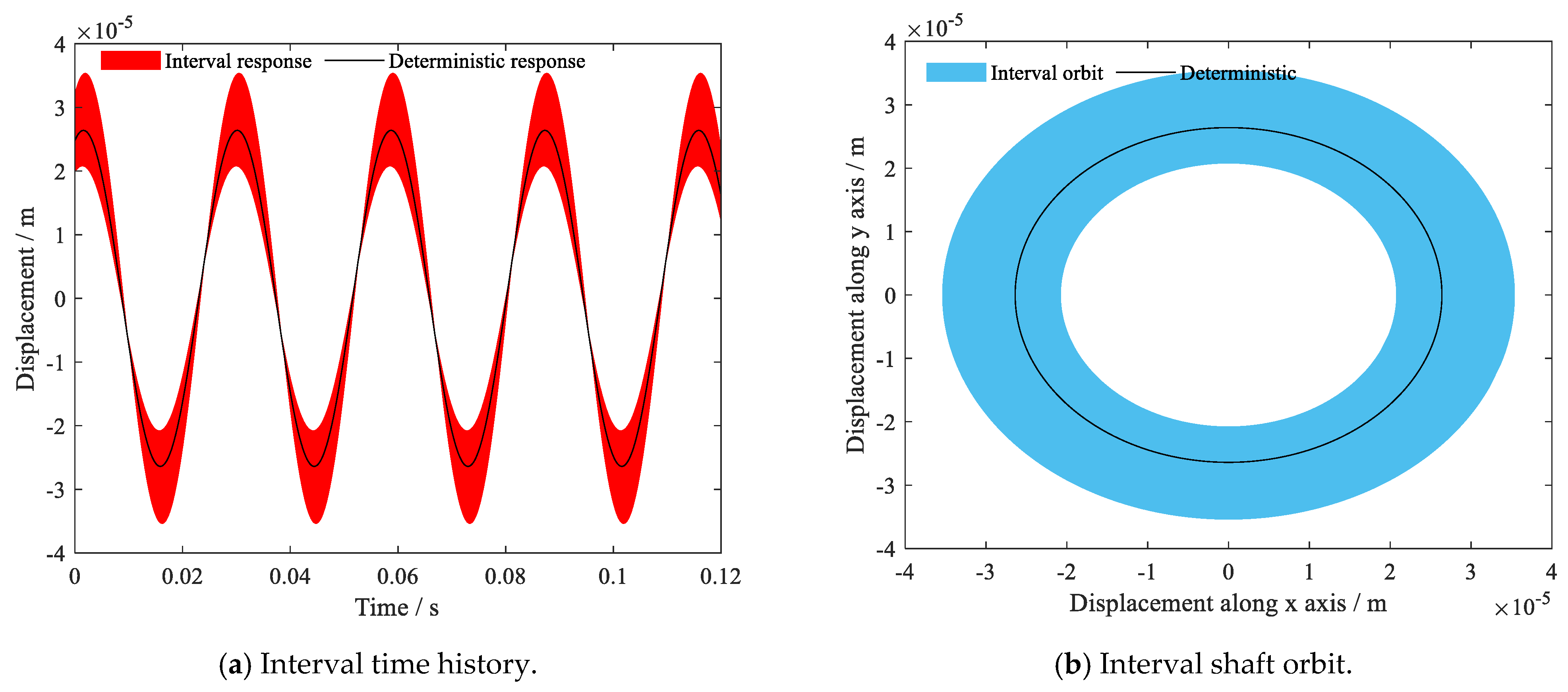
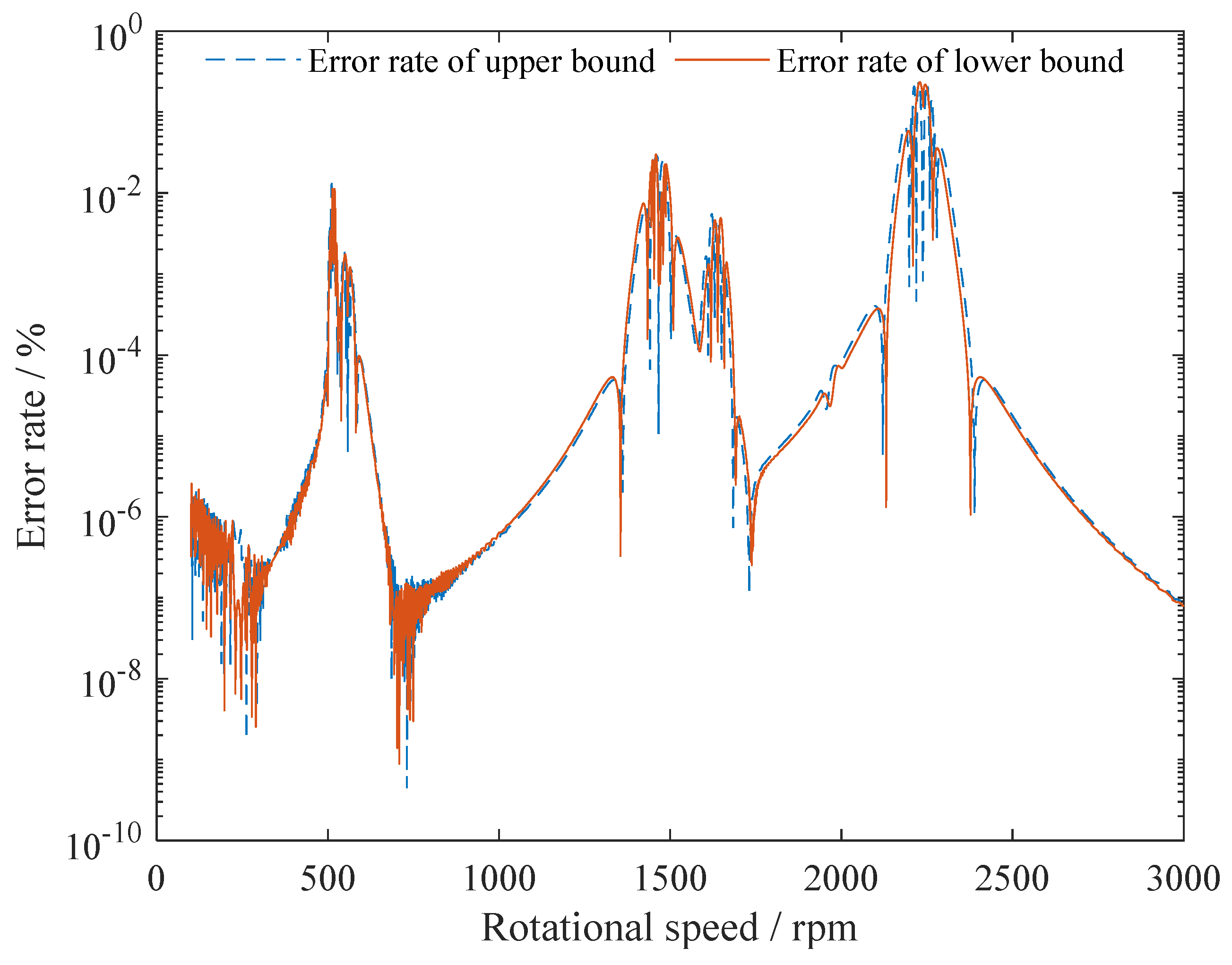
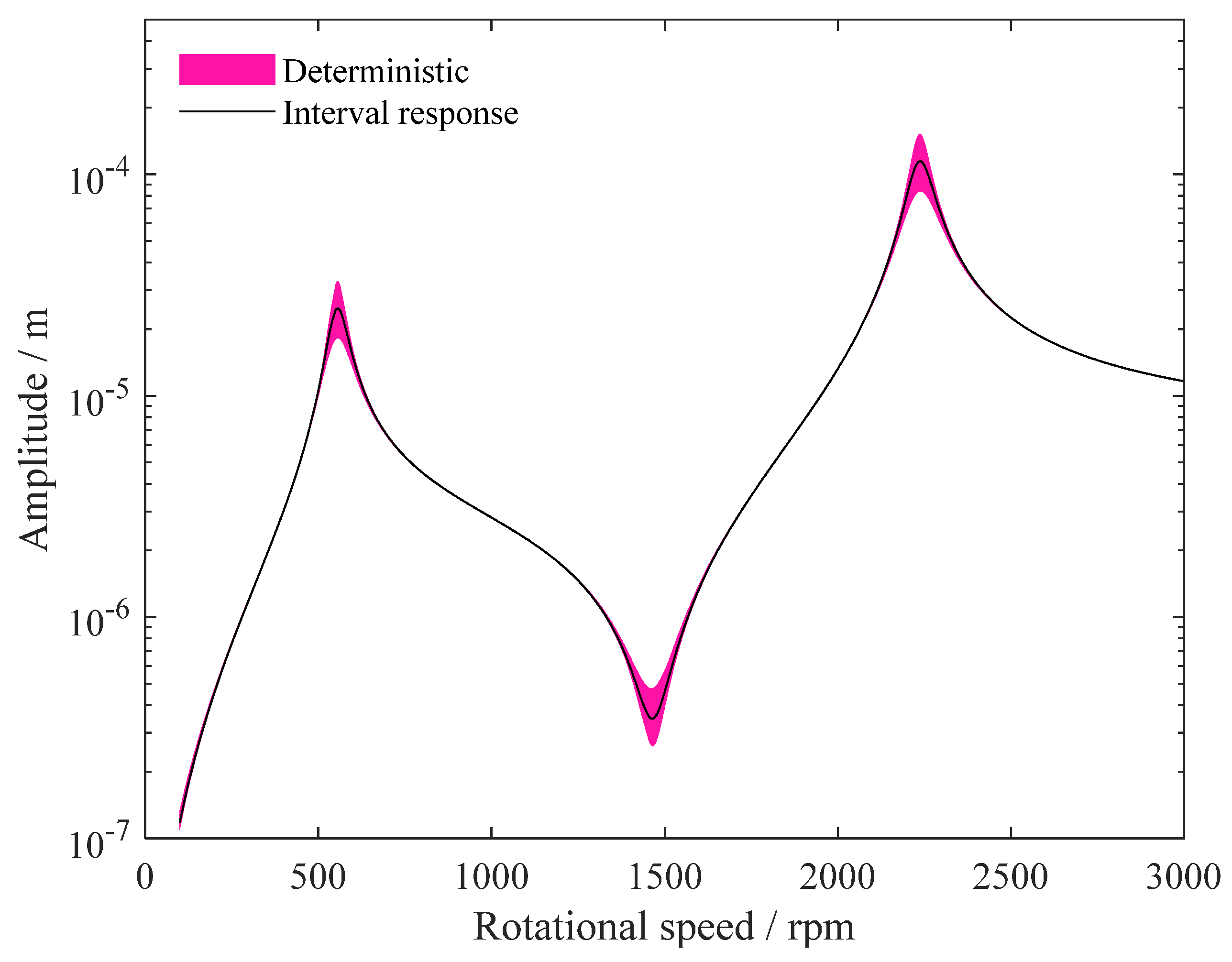
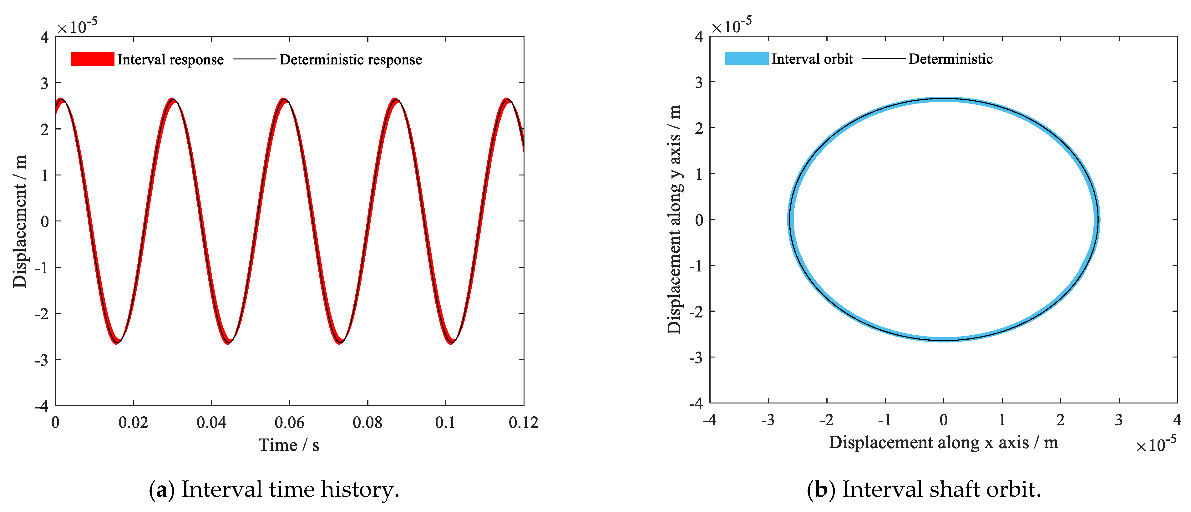
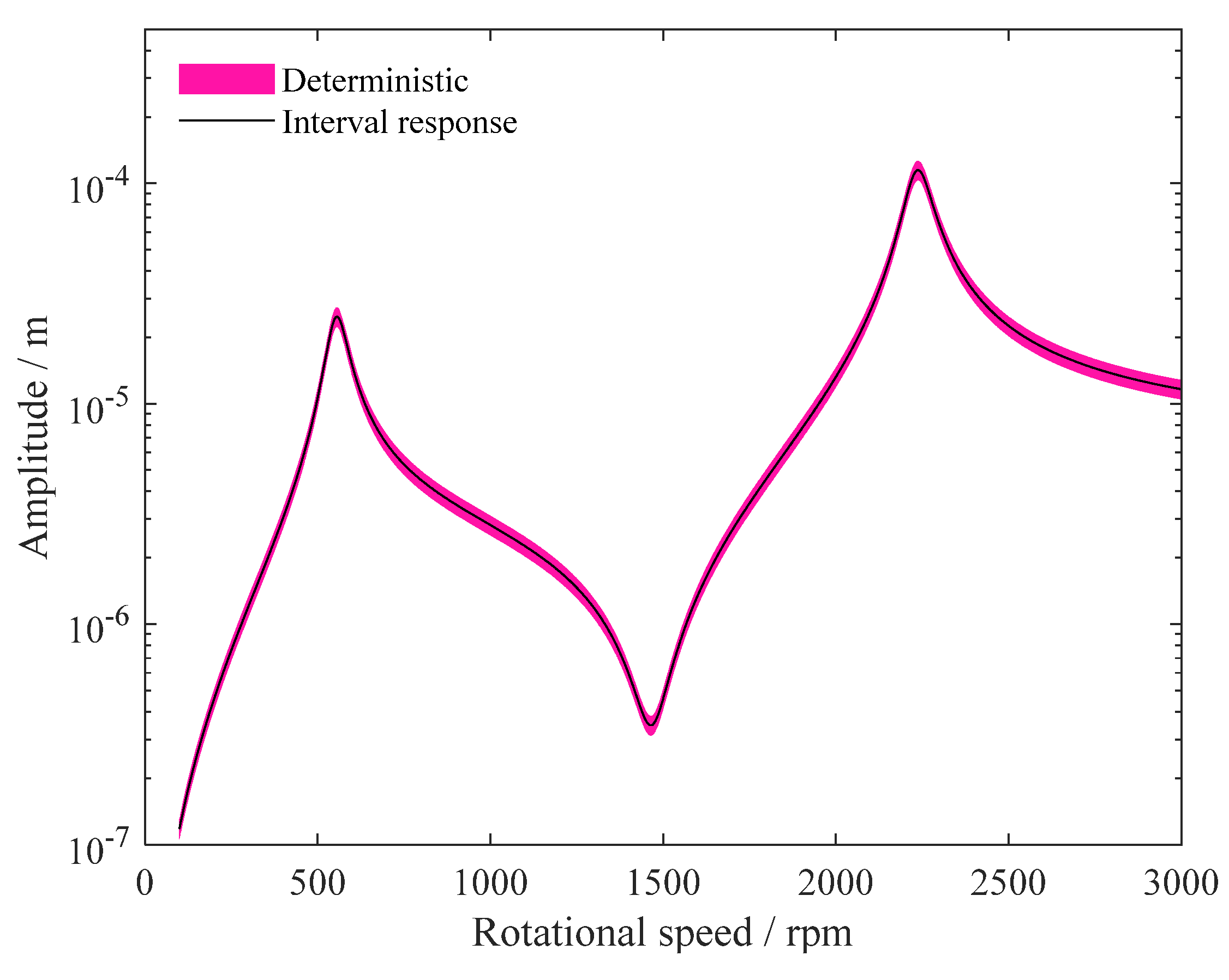
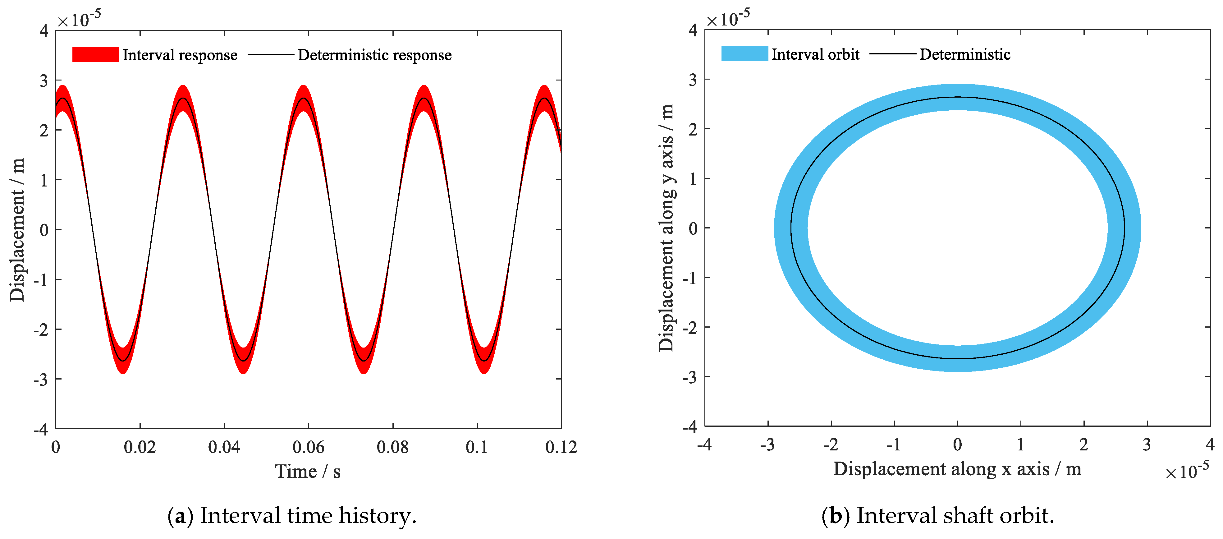
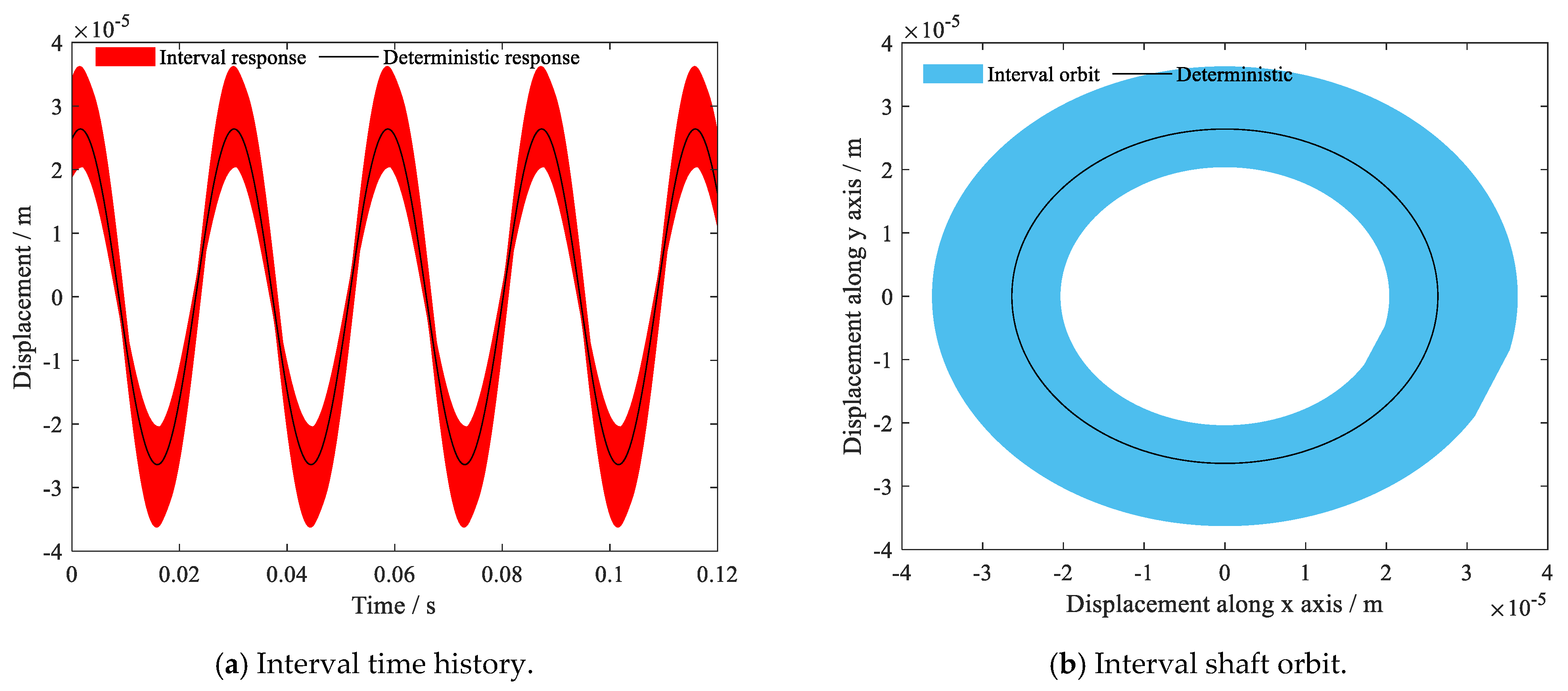
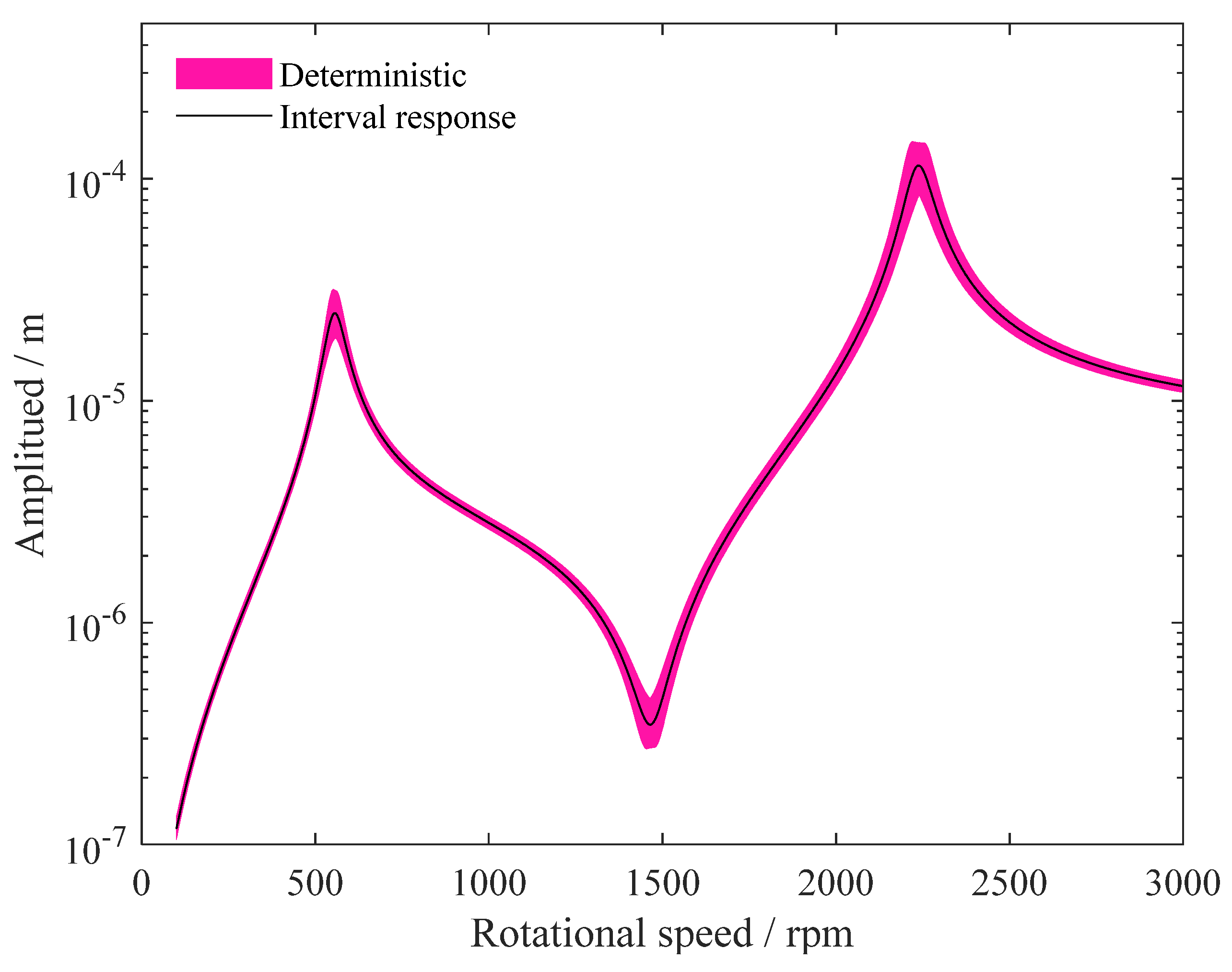
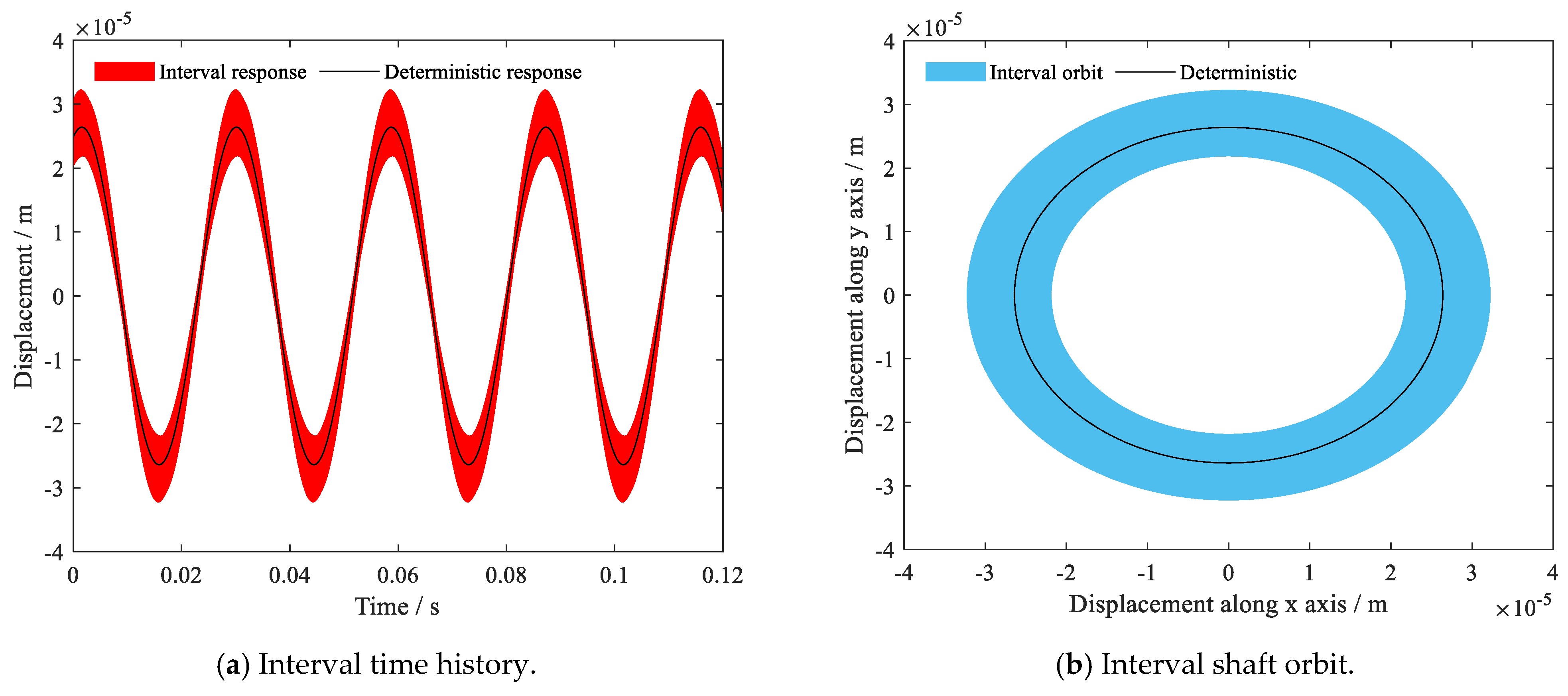
4. Results and Discussion

The rotor-bearing system considered in Figure 1 is investigated from the deterministic and indeterministic aspects. In the beginning, the modal characteristics based on the deterministic parameter set given in Table 1 are presented. Based on the simulations, the Campbell diagram of the rotating system is demonstrated in Figure 3. The results show that, in the interested speed range, there are two forward synchronous critical speeds, i.e., 556 rpm and 2234 rpm. The first two order mode shapes of the rotating system are shown in Figure 4, which correspond to the natural frequencies equal to the critical speeds. These deterministic characteristics help readers to understand the inherent properties of the rotating system under study and provide guidance for uncertainty analysis.
As mentioned in the introduction, there are plenty of uncertainty sources in a rotor system supported by oil-film bearings, such as the service environment evolutions, variable geometry [39], tribofilm-asperity interaction [40], and bearing clearance fluctuations [41]. Based on the deterministic analysis, uncertainty propagation algorithms can be further incorporated by employing the procedures elaborated on in Section 3. In the following section, the steady state responses presented are extracted at the disk 1 node. Time history is the x-directional displacement at 2100 rpm. In calculations, the order of the surrogate model is 4, which proves to be efficient as well as accurate.
The first interval variable considered is shaft stiffness, which is often reflected in the elastic modulus. A 3% interval coefficient is applied in the simulation and the obtained interval results are given in Figure 5 and Figure 6, including the steady state response, the time history, and shaft orbit. It is shown that the interval elastic modulus arouses overall impact in the studied speed scope, except that the deviations are trivial when the rotation speed is quite low. Moreover, the responses after the first critical speed are more affected, especially the second mode. A special feature observed from the interval frequency response is that the deviation of amplitude around the second critical speed is small, although the resonant region is expanded, which is caused by the frequency deviations. Indeed, the elastic modulus has crucial effects on the natural properties of the rotating system. On the second mode resonance point, the response amplitude is almost the same as the deterministic value, i.e., the interval response upper bound precisely encloses the original peak without penetration. Nevertheless, the interval time history presented in Figure 6a shows that the effects of uncertainty are mainly exhibited around peaks. The interval shaft orbit in Figure 6b demonstrates significant deviations from the deterministic orbit, indicating that the shaft can have an arbitrary trajectory in the interval bands due to uncertain elastic modulus, which is often observed in measured orbits.
To validate the effectiveness of the obtained solutions, the interval responses subject to the uncertain elastic modulus are further comparatively studied with the results obtained from the crude scanning method. The latter is deemed to be reliable with many evenly-scattered parameter samples [42]. In calculations of the crude scanning method, the considered uncertainty interval is equally divided by the scanning points and the step distance between different scanning points is the same. After comparison, the difference in rates for the response bounds between the results of the Chebyshev method and the scanning method, based on 100 samples, are shown in Figure 7. It is proved that the constructed surrogate model has high accuracy, and the highest error rate is below 1%. It should be noted that the simulation efficiency is much higher compared with the traditional crude sampling-based scanning method.
The bearing length varies due to manufacturing or assembling errors, and 10% uncertainty is introduced in the calculations. According to the interval analysis, the corresponding responses are plotted in Figure 8 and Figure 9. It suggests that the bearing length has less impact on the unbalanced responses of the rotating system. The steady-state responses suggest that only the vibration peaks are deviated, including the resonance and anti-resonance areas. There is no deviation in other rotation speed ranges. The interval time history and shaft orbit shown in Figure 9 reveal that the displacement peaks in the time history and orbit ranges are minorly deviated. This can be explained since the bearing length is already small and the effects of bearing length are not dominant since the short bearing hypothesis is used. Mass unbalance of a rotor system can change with time because of friction and wear of critical components. Thus, it is reasonable to consider interval uncertainty in the unbalance magnitude. Figure 10 and Figure 11 demonstrate the uncertain responses of the rotating system under 10% uncertainty of the mass unbalance included. We can notice that the uncertain unbalance magnitude has an overall impact on the steady-state responses and the deviation is proportional to the deterministic responses for all rotation speeds. It is essential this way since the rotating system is linearly dependent on the mass unbalance and it does not alter the inherent modal property of the rotor system. The deviations in the time history and shaft orbit also indicate that the interval unbalance causes moderate fluctuations.
Next, we investigate a two-dimensional interval case, i.e., considering the interval bearing length and elastic modulus simultaneously. Their interval coefficients are the same as in previous cases. As expected, the interval responses demonstrated in Figure 12 show combined effects of the uncertainties. The resonant regions are also expanded. However, the amplitudes in the second mode are deviated rather than barely enveloped, as in Figure 5. The time history shows striking deviations in all time stamps and the shaft orbit is distributed significantly, as evidenced in Figure 13. Finally, a more complicated situation is studied. We studied four interval parameters at the same time, i.e., the interval elastic modulus with 1.5% uncertainty, the interval bearing length with 5% uncertainty, the interval lubricant viscosity with 5% uncertainty, and the interval mass unbalance with 5% uncertainty. The corresponding results for this compound case are illustrated in Figure 14 and Figure 15. For such complex simulation cases, the traditional scanning method introduces an overwhelming computational burden aroused by the massive parameter sampling. For instance, there will be 1004 samples in total if we use 100 samples for an individual interval uncertainty in the scanning process. Indeed, a parameter sample requires a complete execution of solving the original rotor-bearing system. Thus, it is obvious that the Chebyshev method used in the current study has superiority. In Figure 14, we can find that even though there are small deviation degrees in each parameter, the steady state dynamic responses are notably affected. Again, the first mode is linearly deviated while the second mode is expanded. To quantitatively evaluate the dispersion of critical speeds, the bounds of the first two critical speeds are given in Table 2. The results also suggest that the second critical speed is more influenced. However, the final dispersions of critical speeds are not the sum of the deviation coefficients of individual interval parameters.

5. Conclusions

In this paper, the interval uncertain responses of a rotor equipped with oil-film bearings are investigated. The deterministic solution process is established following a finite element analysis and the hydrodynamic bearing theory. Surrogate modeling for uncertainty propagation analysis is established according to the Chebyshev interval method. Various interval parameters are considered, and the results are presented. The steady state response, time history, and shaft orbit are discussed. It is found that the elastic modulus has global effects while the bearing length has local impacts. Combined effects are observed for the multi-source cases. The accuracy validation suggests that the implemented surrogate model has high precisions and is superior to the traditional scanning method in terms of efficiency. The results reported can guide the robust dynamical studies of such rotor systems and benefit the design process. It is also helpful in determining which parameter should be specially treated. Future studies will focus on strategies for utilizing the optimization of such rotor-bearing systems and reducing the impact of uncertainty.

Author Contributions

Conceptualization, J.M. and C.F.; methodology, C.F.; software, C.F. and Z.Z.; validation, K.L. and Z.Z.; formal analysis, C.F.; investigation, J.M. and Z.Z.; resources, K.L.; data curation, Z.Z. and Y.Y.; writing—original draft preparation, C.F.; writing—review and editing, Y.Y. and Z.Z.; visualization, Z.Z.; supervision, C.F.; project administration, J.M.; and funding acquisition, J.M. All authors have read and agreed to the published version of the manuscript.

Funding

This research was funded by the National Natural Science Foundation of China, grant number 52205089, and the Guangdong Basic and Applied Basic Research Foundation, grant number 2021A1515110767.

Data Availability Statement

Not applicable.

Conflicts of Interest

The authors declare no conflict of interest.

References

  1. Chasalevris, A.; Louis, J.C. Evaluation of transient response of turbochargers and turbines using database method for the nonlinear forces of journal bearings. Lubricants 2019, 7, 78. [Google Scholar] [CrossRef] [Green Version]
  2. Ma, J.; Fu, C.; Zhang, H.; Chu, F.; Shi, Z.; Gu, F.; Ball, A.D. Modelling non-Gaussian surfaces and misalignment for condition monitoring of journal bearings. Measurement 2021, 174, 108983. [Google Scholar] [CrossRef]
  3. Dang, P.V.; Chatterton, S.; Pennacchi, P. The effect of the pivot stiffness on the performances of five-pad tilting pad bearings. Lubricants 2019, 7, 61. [Google Scholar] [CrossRef] [Green Version]
  4. Roy, B.; Dey, S. Machine learning-based performance analysis of two-axial-groove hydrodynamic journal bearings. Proc. Inst. Mech. Eng. Part J J. Eng. Tribol. 2021, 235, 2211–2224. [Google Scholar] [CrossRef]
  5. Xu, B.; Zang, C.; Zhang, G. Intelligent approach to robust design optimization of a rotor system due to its support stiffness uncertainty. Shock Vib. 2020, 2020, 2564679. [Google Scholar] [CrossRef] [Green Version]
  6. Xiang, G.; Yang, T.; Guo, J.; Wang, J.; Liu, B.; Chen, S. Optimization transient wear and contact performances of water-lubricated bearings under fluid-solid-thermal coupling condition using profile modification. Wear 2022, 502–503, 204379. [Google Scholar] [CrossRef]
  7. Moustafa, K.A.F. Stability of journal bearing-rotor systems with interval-bearing parameters. J. Vib. Control 1999, 5, 941–953. [Google Scholar] [CrossRef]
  8. Wale, G.D.; Mba, D. Identifying and minimising uncertainty for experimental journal bearing studies. Int. J. Rotating Mach. 2005, 2005, 591329. [Google Scholar] [CrossRef]
  9. Fu, C.; Zhu, W.; Ma, J.; Gu, F. Static and dynamic characteristics of journal bearings under uncertainty: A nonprobabilistic perspective. J. Eng. Gas Turbines Power 2022, 144, 071012. [Google Scholar]
  10. Didier, J.; Sinou, J.J.; Faverjon, B. Study of the non-linear dynamic response of a rotor system with faults and uncertainties. J. Sound Vib. 2012, 331, 671–703. [Google Scholar] [CrossRef] [Green Version]
  11. Cavalini Jr, A.A.; Lara-Molina, F.A.; Sales, T.d.P.; Koroishi, E.H.; Steffen, V., Jr. Uncertainty analysis of a flexible rotor supported by fluid film bearings. Lat. Am. J. Solids Struct. 2015, 12, 1487–1504. [Google Scholar] [CrossRef]
  12. Chen, S.; Xiang, G.; Fillon, M.; Guo, J.; Wang, J.; Cai, J. On the tribo-dynamic behaviors during start-up of water lubricated bearing considering imperfect journal. Tribol. Int. 2022, 174, 107685. [Google Scholar] [CrossRef]
  13. Fu, C.; Sinou, J.J.; Zhu, W.D.; Lu, K.; Yang, Y.F. A state-of-the-art review on uncertainty analysis of rotor systems. Mech. Syst. Signal Process. 2023, 183, 109619. [Google Scholar] [CrossRef]
  14. Ma, J.; Fu, C.; Zhu, W.; Lu, K.; Yang, Y. Stochastic analysis of lubrication in misaligned journal bearings. J. Tribol. 2022, 144, 081802. [Google Scholar] [CrossRef]
  15. Lin, L.; He, M.; Ma, W.; Wang, Q.; Zhai, H.; Deng, C. Dynamic characteristic analysis of the multi-stage centrifugal pump rotor system with uncertain sliding bearing structural parameters. Appl. Sci. 2022, 10, 473. [Google Scholar] [CrossRef]
  16. Fu, C.; Feng, G.J.; Ma, J.J.; Lu, K.; Yang, Y.F.; Gu, F.S. Predicting the dynamic response of dual-rotor system subject to interval parametric uncertainties based on the non-intrusive metamodel. Mathematics 2020, 8, 736. [Google Scholar] [CrossRef]
  17. Denimal, E.; Sinou, J.J. Advanced kriging-based surrogate modelling and sensitivity analysis for rotordynamics with uncertainties. Eur. J. Mech.-A/Solids 2021, 90, 104331. [Google Scholar] [CrossRef]
  18. Stocki, R.; Lasota, R.; Tauzowski, P.; Szolc, T. Scatter assessment of rotating system vibrations due to uncertain residual unbalances and bearing properties. Comput. Assist. Methods Eng. 2017, 19, 95–120. [Google Scholar]
  19. Fu, C.; Zhu, W.D.; Yang, Y.F.; Zhao, S.B.; Lu, K. Surrogate modeling for dynamic analysis of an uncertain notched rotor system and roles of Chebyshev parameters. J. Sound Vib. 2022, 524, 116755. [Google Scholar] [CrossRef]
  20. Sun, X.; Sepahvand, K.K.; Marburg, S. Stability analysis of rotor-bearing systems under the influence of misalignment and parameter uncertainty. Appl. Sci. 2021, 11, 7918. [Google Scholar] [CrossRef]
  21. Garoli, G.Y.; Castro, H.F.d. Analysis of a rotor-bearing nonlinear system model considering fluid-induced instability and uncertainties in bearings. J. Sound Vib. 2019, 448, 108–129. [Google Scholar] [CrossRef]
  22. Geng, B.; Zuo, Y.; Jiang, Z.; Feng, K.; Wang, C.; Wang, J. A double integral method for quantitative evaluation of influence on thin-walled casing response caused by bearing uncertainties. Chin. J. Aeronaut. 2020, 33, 2372–2381. [Google Scholar] [CrossRef]
  23. Medina, L.; Ruiz, R.; Di’az, S. A simple approach to determine uncertainty bounds on bearing rotordynamic coefficients identification. In Proceedings of the Turbo Expo: Power for Land, Sea, and Air, Berlin, Germany, 9–13 June 2008; pp. 1279–1287. [Google Scholar]
  24. Tauviqirrahman, M.; Jamari, J.; Wicaksono, A.A.; Muchammad, M.; Susilowati, S.; Ngatilah, Y.; Pujiastuti, C. CFD analysis of journal bearing with a heterogeneous rough/smooth surface. Lubricants 2021, 9, 88. [Google Scholar] [CrossRef]
  25. Da Silva, H.A.P.; Nicoletti, R. Design of tilting-pad journal bearings considering bearing clearance uncertainty and reliability analysis. J. Tribol. 2019, 141, 011703. [Google Scholar] [CrossRef]
  26. Li, Z.; Jiang, J.; Tian, Z. Stochastic dynamics of a nonlinear misaligned rotor system subject to random fluid-induced forces. J. Comput. Nonlinear Dyn. 2016, 12, 011004. [Google Scholar] [CrossRef]
  27. Alves, D.S.; Daniel, G.B.; Castro, H.F.d.; Machado, T.H.; Cavalca, K.L.; Gecgel, O.; Dias, J.P.; Ekwaro-Osire, S. Uncertainty quantification in deep convolutional neural network diagnostics of journal bearings with ovalization fault. Mech. Mach. Theory 2020, 149, 103835. [Google Scholar] [CrossRef]
  28. Kiureghian, A.D.; Ditlevsen, O. Aleatory or epistemic? Does it matter? Struct. Saf. 2009, 31, 105–112. [Google Scholar] [CrossRef]
  29. Fu, C.; Xu, Y.D.; Yang, Y.F.; Lu, K.; Gu, F.S.; Ball, A. Response analysis of an accelerating unbalanced rotating system with both random and interval variables. J. Sound Vib. 2020, 466, 115047. [Google Scholar] [CrossRef]
  30. Wu, J.; Zhang, Y.; Chen, L.; Luo, Z. A Chebyshev interval method for nonlinear dynamic systems under uncertainty. Appl. Math. Model. 2013, 37, 4578–4591. [Google Scholar] [CrossRef]
  31. Fu, C.; Zheng, Z.; Zhu, W.; Lu, K.; Yang, Y. Non-intrusive frequency response analysis of nonlinear systems with interval uncertainty: A comparative study. Chaos Solitons Fractals 2022, 165, 112815. [Google Scholar] [CrossRef]
  32. Ma, Y.; Liang, Z.; Chen, M.; Hong, J. Interval analysis of rotor dynamic response with uncertain parameters. J. Sound Vib. 2013, 332, 3869–3880. [Google Scholar] [CrossRef]
  33. Fu, C.; Zhu, W.D.; Zheng, Z.L.; Sun, C.Z.; Yang, Y.F.; Lu, K. Nonlinear responses of a dual-rotor system with rub-impact fault subject to interval uncertain parameters. Mech. Syst. Signal Process. 2022, 170, 108827. [Google Scholar] [CrossRef]
  34. Wang, J.; Liu, Y.; Qin, Z.; Ma, L.; Chu, F. Dynamic performance of a novel integral magnetorheological damper-rotor system. Mech. Syst. Signal Process. 2022, 172, 109004. [Google Scholar] [CrossRef]
  35. Zhao, S.; Zhang, L.; Zhu, R.; Han, Q.; Qin, Z.; Chu, F. Modeling approach for flexible shaft-disk-drum rotor systems with elastic connections and supports. Appl. Math. Model. 2022, 106, 402–425. [Google Scholar] [CrossRef]
  36. Friswell, M.I.; Penny, J.E.; Garvey, S.D.; Lees, A.W. Dynamics of Rotating Machines; Cambridge University Press: Cambridge, UK, 2010. [Google Scholar]
  37. Kornaev, A.V.; Kornaev, N.V.; Kornaeva, E.P.; Savin, L.A. Application of artificial neural networks to calculation of oil film reaction forces and dynamics of rotors on journal bearings. Int. J. Rotating Mach. 2017, 2017, 9196701. [Google Scholar] [CrossRef] [Green Version]
  38. Cameron, A. Basic Lubrication Theory; Ellis Horwood: Chichester, UK, 1981. [Google Scholar]
  39. Chasalevris, A.; Dohnal, F. Vibration quenching in a large scale rotor-bearing system using journal bearings with variable geometry. J. Sound Vib. 2014, 333, 2087–2099. [Google Scholar] [CrossRef]
  40. Ma, J.; Zhang, H.; Lou, S.; Chu, F.; Shi, Z.; Gu, F.; Ball, A.D. Analytical and experimental investigation of vibration characteristics induced by tribofilm-asperity interactions in hydrodynamic journal bearings. Mech. Syst. Signal Process. 2021, 150, 107227. [Google Scholar] [CrossRef]
  41. Papadopoulos, C.A.; Nikolakopoulos, P.G.; Gounaris, G.D. Identification of clearances and stability analysis for a rotor-journal bearing system. Mech. Mach. Theory 2008, 43, 411–426. [Google Scholar] [CrossRef]
  42. Fu, C.; Zheng, Z.L.; Zhu, W.D.; Xie, Z.L.; Qin, W.Y.; Lu, K. Nonlinear dynamics of discontinuous uncertain oscillators with unilateral constraints. Chaos 2022, 32, 123112. [Google Scholar] [CrossRef]
Figure 1. Rotor system model supported by oil-film bearings.
Lubricants 10 00354 g001
Figure 2. A simulation flowchart of the uncertainty analysis for the rotating system.
Lubricants 10 00354 g002
Figure 3. Campbell diagram of the system.
Lubricants 10 00354 g003
Figure 4. Mode shapes of the system at critical speeds.
Lubricants 10 00354 g004
Figure 5. The steady state response of the system under interval elastic modulus.
Lubricants 10 00354 g005
Figure 6. Time history and orbit of the system under interval elastic modulus.
Lubricants 10 00354 g006
Figure 7. Error analysis of the results under interval elastic modulus.
Lubricants 10 00354 g007
Figure 8. The steady state response of the system under interval bearing length.
Lubricants 10 00354 g008
Figure 9. Time history and orbit of the system under interval bearing length.
Lubricants 10 00354 g009
Figure 10. The steady state response of the system under interval mass unbalance.
Lubricants 10 00354 g010
Figure 11. Time history and orbit of the system under interval mass unbalance.
Lubricants 10 00354 g011
Figure 12. The steady state response of the dynamical system under interval elastic modulus and bearing length.
Lubricants 10 00354 g012
Figure 13. Time history and orbit of the dynamical system under interval elastic modulus and bearing length.
Lubricants 10 00354 g013
Figure 14. The steady state response of the dynamical system under interval elastic modulus.
Lubricants 10 00354 g014
Figure 15. Time history and orbit of the rotating system under interval elastic modulus.
Lubricants 10 00354 g015
Table 1. Rotor model configuration.
NameValueNameValue
Length of rotor1.5 mThickness of disk0.07 m
Diameter of rotor0.05 mDiameter of disk 10.06 m
Young’s modulus 2.1 × 10 11   N / m 2 Diameter of disk 20.07 m
Lubricant viscosity0.1 Pa·sUnbalance amount0.001 kg
Bearing length0.015 mBearing clearance 5 × 10 5   m
Table 2. Bounds of the first two critical speeds.
Lower BoundUpper Bound
First critical speed551 rpm562 rpm
Second critical speed2219 rpm2256 rpm
Publisher’s Note: MDPI stays neutral with regard to jurisdictional claims in published maps and institutional affiliations.

