Article

Effect of Y on Microstructure and Properties of Al0.8FeCrCoNiCu0.5 High Entropy Alloy Coating on 5083 Aluminum by Laser Cladding

1
School of Mechanical and Vehicle Engineering, West Anhui University, Luan 237010, China
2
College of Electromechanical Engineering, Changchun University of Science and Technology, Changchun 130012, China
3
Advanced Forming and Green Manufacturing Technology Laboratory of West Anhui University, West Anhui University, Luan 237010, China
4
Gongqing Institute of Science and Technology, Jiujiang 332020, China
*
Author to whom correspondence should be addressed.
Lubricants 2023, 11(2), 50; https://doi.org/10.3390/lubricants11020050
Submission received: 16 December 2022 / Revised: 8 January 2023 / Accepted: 28 January 2023 / Published: 30 January 2023

Abstract

:
To improve the surface properties of 5083 aluminum, Al0.8FeCrCoNiCu0.5Yx (x = 0, 0.05, 0.1, and 0.2) high-entropy alloy coatings were prepared by laser cladding. The phase structure and microstructure of the Al0.8FeCrCoNiCu0.5Yx coatings were characterized by XRD and SEM. The tribological properties of the coating were tested by a friction and wear tester. An electrochemical workstation tested the corrosion resistance of the coating. The results show that when Y content is less than 0.2, the Al0.8FeCrCoNiCu0.5Yx coating is in the FCC1, BCC1, and BCC2 phases. When Y is added to 0.2, the coating appears rich in the Y phase. With the increased Y content, the hardness of the coating can increase. The average hardness of Y0, Y0.05, Y0.1, and Y0.2 are 479HV0.2, 517HV0.2, 532HV0.2, and 544HV0.2, respectively. Microstructure evolution leads to an increase in the hardness of the coating. The effect of Y on the wear resistance of the Al0.8FeCrCoNiCu0.5Yx coatings is consistent with the hardness. Al0.8FeCrCoNiCu0.5Y0.2 coating has the lowest wear rate, at is 8.65 × 10⁻⁶ mm3/Nm. The corrosion current density of Al0.8FeCrCoNiCu0.5Y0.05 and Al0.8FeCrCoNiCu0.5Y0.1 coatings is in the order of 10−8, which is less than Al0.8FeCrCoNiCu0.5Y0.2 and Al0.8FeCrCoNiCu0.5. The performance of each component coating is superior to that of the substrate.

1. Introduction

Since 2004, the design idea of high entropy alloys (HEA) has broken the traditional alloy concept’s bottleneck and broadened the multi-principal alloy application field [1]. Due to the high entropy effect of HEAs, their phase is usually composed of body-centered cubic (BCC) and face-centered cubic (FCC) solid solutions, which are less prone to complex intermetallic compounds [2,3,4,5]. Given the effects of solution strengthening, lattice distortion, and slow diffusion, HEAs can display excellent properties, such as high strength and hardness, good ductility, and wear resistance, which gives them broad development potential and application prospects in necessary engineering fields such as vehicles, ships, aerospace, etc. [6,7].
Block high-entropy alloys and high-entropy alloy coatings are the two most common ways to prepare high-entropy alloys. Research on high-entropy alloy blocks has been mainly focused on melt-casting and powder metallurgy. However, because the main elements that make up high-entropy alloys often include Ni, Co, Ti, and other precious metal elements, the cost of high entropy alloy block prepared by the above method is higher. In addition, bulk high-entropy alloys prepared using a vacuum electric arc furnace are small and simple in shape, making it difficult to meet the industry’s needs for preparing large-sized and complex-shaped parts, thereby hindering the application of simple high-entropy alloy blocks in industrial production. The coating technology has come into being to compensate for the high cost, non-uniform composition, and size limitation of preparing block high entropy alloys. Traditional coating preparation techniques include mechanical alloying, magnetron sputtering, thermal spraying, and deposition methods.
Laser cladding (LD) is the ordinary method of coating preparation because of its fast cooling rate and low heat output. Some institutions have carried out the practice of HEA coatings by LD [8]. Among the many high-entropy alloy material systems, Fe, Co, Cr, and Ni have small differences in mixing enthalpy and atomic size, and easily form a homogeneous solid solution in the process of preparing high-entropy alloy coatings. Hence, the FeCoCrNi system of high-entropy alloy coatings is a current research hotspot. Furthermore, adding non-metallic elements, hard ceramic phases, and heat treatment to the above material system helps improve the wear resistance of the high-entropy alloy coating.
Sha et al. prepared AlxCoCrFe2.7MoNi (x = 0, 0.5, 1.0, 1.5, 2.0) high-entropy alloy coatings on a pure iron surface by laser melting, and found that the increase in Al element content promoted the release of Mo from the Mo-rich BCC phase to form a (Mo, Cr)-rich σ phase, which led to the increase in hardness and wear resistance of the coatings [9]. Liu et al. prepared CoCrFeNiTi high-entropy alloy coatings by laser melting and showed that the hardness of CoCrFeNiTi coatings could be increased to 700 HV0.3, and the wear resistance was significantly improved [10]. Zhang et al. found that the corrosion resistance of AlCoCrFeNi HEA coatings was 7.6 times higher than that of 304 stainless steel. In addition, the component composition significantly modulates the organization and performance of the HEA coatings [11]. Martin et al. investigated the impact of Ti on the structure and properties of AlCoCrFeNi HEA. As the Ti content rises, the coating’s microstructure becomes more heterogeneous, and its hardness and wear resistance increase [12]. Zhang et al. doped B element in FeCrNiCo high entropy alloy coating, indicating that FeCrNiCoBx coating is mainly a simple FCC solid solution containing boride precipitation. When 0.5 ≤ x ≤ 1.0, the hardness and corrosion resistance of the high entropy alloy coating increase with the increase of boron content; When x is close to 1.25, the corrosion resistance of the coating becomes poor [13]. Ma et al. found that Nb can promote the evolution of the structure of AlCoCrFeNi HEA from hypo eutectic to hyper eutectic and reduce the yield strength and hardness [14]. He et al. prepared a AlxCu0.7Si0.1By high entropy alloy coating on Q235 steel surface by using a laser melting technique and investigated the effect of B addition on the solid solution, strengthening the ability of the coating, and found that the addition of B content could improve the hardness of the coating. The Al2.3Cu0.7Si0.1B0.6 coating showed ultra-high hardness and wear resistance [15]. Cai investigated the effect of TiC high entropy alloy coating properties and found that the addition of TiC resulted in the refinement of the coating grains and the increase of dislocation density, which made the coating more resistant to potential plastic deformation and thus showed better performance. However, too many large grains also became more sources of cracking, and the coating had better friction and wear resistance when the TiC content was 10%. The coating has better friction and wear resistance when the TiC content is 10% [16].
Rare earth elements are known as “industrial vitamins”. Some scholars have prepared nickel-based coatings containing rare earth elements or rare earth oxide on aluminium using laser technology [17,18,19,20]. The addition of rare earth can significantly improve the coating’s forming quality and mechanical properties. Some scholars also studied the effect of adding rare earth on the structure and properties of HEAs [21,22,23]. However, the research on laser cladding of high entropy alloy containing rare earth on 5083 aluminum alloy is still lacking [24,25,26].
The melting point of Y is 1522 °C, which is lower than other frequently-used rare earth elements or rare earth oxides, such as Y2O3 (2410 °C) and CeO2 (2397 °C). Furthermore, its melting point is less than the boiling point of aluminum (2372 °C), which can also avoid excessive substrate dilution due to the high melting point of added elements during LD. It was discovered in previous research that the melting point of aluminum is much lower than that of conventional coating materials, such as iron-based alloys and nickel-based alloy, which causes aluminum to float to the molten pool in large quantities during laser processing. The reaction of materials easily generates intermetallic compounds, which lead to defects such as porosity and cracks. In this study, using the unique high-entropy effect of high-entropy alloys, an Al0.8FeCrCoNiCu0.5Yx (x = 0, 0.05, 0.1, 0.2) high-entropy alloy coating was prepared on the surface of aluminum alloy by laser cladding.
Our research group has prepared Al0.8FeCrCoNiCu0.5 coating, which can improve the substrate’s wear resistance and corrosion resistance [27]. In this research, to improve the coating properties and investigate the mechanism of the effect of Y elements on the properties of HEAs, the characteristics of Al0.8FeCrCoNiCu0.5Yx (x = 0, 0.05, 0.1, 0.2) HEA coating was studied.

2. Materials and Methods

The coaxial powder feeding method was used to carry out the laser cladding experiment, and the CO2 laser was selected. The laser adopts the DC050 type, and the output wavelength is 1063 um, the maximum output power is 5000 W, and the output beam mode is quasi-basic mode Gaussian beam. The output beam mode of the laser is quasi-basic mode Gaussian beam, and the beam quality factor is greater than 0.9, which can realize continuous and pulse laser output modes. The pulse mode is a rectangular pulse laser formed by the electronic shutter timing switch. The motion apparatus was a CNC machine. Al, Cr, Fe, Co, Ni, Cu, B, and Si powders produced by atomization or reduction methods were selected, all with purity greater than 99.5% and a particle size of 200–325 mesh. Before the laser deposition preparation, the mixed powders were fully stirred and dried using a planetary ball mill (QM-QX) to ensure the powder’s continuity, fluidity, and homogeneity during the powder-feeding process. Ball milling is carried out in a non-metallic ZrO2 ceramic ball mill tank filled with argon gas to prevent the introduction of additional metallic elements. Due to the low melting point of Al, it is necessary to control the milling speed and time to prevent explosion during milling. After ball milling, the powder is dried in a vacuum drying oven to avoid the formation of hydrogen pores in the coating due to the adsorption of moisture by the powder. Finally, the sealing equipment is used. Figure 1 depicts the laser cladding schematic diagram.
For the substrate, 5083 aluminium was selected. After extensive process tests, the following parameters were selected: laser power 1850 W, scanning speed 120 mm/min, powder feeding rate 5.6 g/min, pulse frequency 50 Hz, duty cycle 70%. The metallographic samples were cut by wire cutting according to the characterization requirements. Grind and polish the sample section. Configure the aqua regia corrosion section for about the 30 s, and clean it with ethanol. The tissue observation of the high-entropy alloy coating was carried out using a mixed solution of hydrochloric acid and nitric acid (volume ratio 3:1) for corrosion, and the corrosion time was controlled within 20~120 s for different alloy compositions. The specimens are cleaned with alcohol and then air-dried. Avoid residual corrosion solution on the surface of the specimen.
The physical phase analysis of the coating was performed using an Empyrean X-ray diffractometer (Empyrean, Malvern Panalytical, Almelo, Netherlands) with a Cu target, a tube voltage of 40 kV, a scanning speed of 4 °/min, and a scanning angle step of 0.05°. The JSM-6510LA SEM was selected for micro-structure observation. An MH-60 microhardness tester was used to test the coating hardness. The load was 200 g, the loading time was 10 s, and the average value of three specimens was taken. MM200 friction was selected for dry-sliding wear testing; the load loading was 98 N, and the test time was 30 min. The friction block was a GCr15 steel ring with a hardness of 61 HRC. Frictional wear data were recorded during the frictional wear test, and the test was repeated three times to obtain the average value. The test load was 98 N, the speed was 400 r/min, and the permitted time was 30 min. The material’s wear rate was determined by calculating the volume of wear. Figure 2 shows the schematic diagram of the wear test.
The dynamic potential polarization curve is currently one of the most convincing measurements in the field of material corrosion resistance evaluation, which can be used to characterize the electrochemical corrosion behavior of materials by the relationship curve between electrode potential and current density. Zaner’s electrochemical workstation was selected for the polarization test. The polarization test uses an electrochemical workstation (Zennium Pro, Zahner, Kronach, Germany). The experiment was carried out at room temperature. A three-electrode working system was used: the working electrode was the experimental sample (WE), the counter electrode (CE) was platinum, and the reference electrode (RE) was a saturated KCl solution. Select 3.5% NaCl solution for the corrosion solution. The scanning range of the polarization curve test is −2~1 V. The scan rate was 5 mV/s. Al0.8FeCrCoNiCu0.5Yx (x = 0, 0.05, 0.1, 0.2) HEA coatings were designed, and the nominal composition was shown in Table 1.

3. Results and Discussion

3.1. XRD Analysis

Figure 3 displays the XRD of the Al0.8FeCrCoNiCu0.5Yx HEA coatings, and the coating consists of BCC, FCC, and Y-rich phases. The BCC1 phase was a disordered BCC solid solution whose diffraction peak was 44.5°, 65.0°, and 82°, similar to α-(Fe,Cr). The diffraction peaks nearby proved that the BCC2 phase was an ordered BCC phase (B2 phase) that is close to the AlNi phase. The FCC1 diffraction peak position was 44.0°, 51.6°, 74.5°, similar to α-Cu. [28]. No new phase is generated when the Y range is from 0.05 to 0.1. The Y-rich phase appeared at Y0.2, indicating that excessive Y cannot be dissolved.

3.2. Microstructure

Figure 4 displays the microstructure of the Al0.8FeCrCoNiCu0.5Yx HEA coatings, and all samples showed a dendritic structure after metallographic corrosion. Compared with the Y0, the structure of the coating containing rare earth elements is more refined, and the reason is that Y belongs to the surface active element, which can reduce the surface tension of the melt pool, reduce the work required for nucleation of critical size, increase the amount of nucleation, and improve the number of crystallites in the tissue per unit area [18,21,29]. Rare earth elements can act as non-autonomous crystallization cores and hinder grain growth [29,30]. When Y is increased to 0.2, the grain size is further refined, but significant differences in the scale between grains appear, and the uniformity deteriorates, as in Figure 4d. The Al0.8FeCrCoNiCu0.5Yx HEA coatings are more sensitive to Y. A moderate amount of Y will refine the organization of the coating, while an excessive amount of Y is not conducive to the homogeneity of the organization.

3.3. Hardness

Figure 5 displays the average hardness of Al0.8FeCrCoNiCu0.5Yx HEAs coatings. The average hardness of Y0, Y0.05, Y0.1, and Y0.2 are 479HV0.2, 517HV0.2, 532HV0.2, and 544HV0.2, respectively. The addition of Y increases the hardness of the coating. On one hand, although the addition of Y does not change the phase structure of the solid solution, the Y element with a large atomic radius can increase the lattice distortion of the reliable solution, and the solution strengthening effect can improve the hardness of the coating. On the other hand, adding Y refines the grains and plays a role in the fine-grain strengthening of the coating. The combined effect of the two increases the hardness of the coatings. For high entropy alloy coatings, the variety of solid solution elements is high, which leads to a large lattice distortion of the alloy. The interaction of the stress field generated by the lattice distortion and the elastic stress field will have a strong pegging effect on the dislocation slip inside the alloy. The pegging effect increases the resistance to dislocation movement. Solid solution and dislocation strengthening make the high entropy alloy exhibit high hardness characteristics. The hardness of each coating is much higher than that of the substrate [31,32].

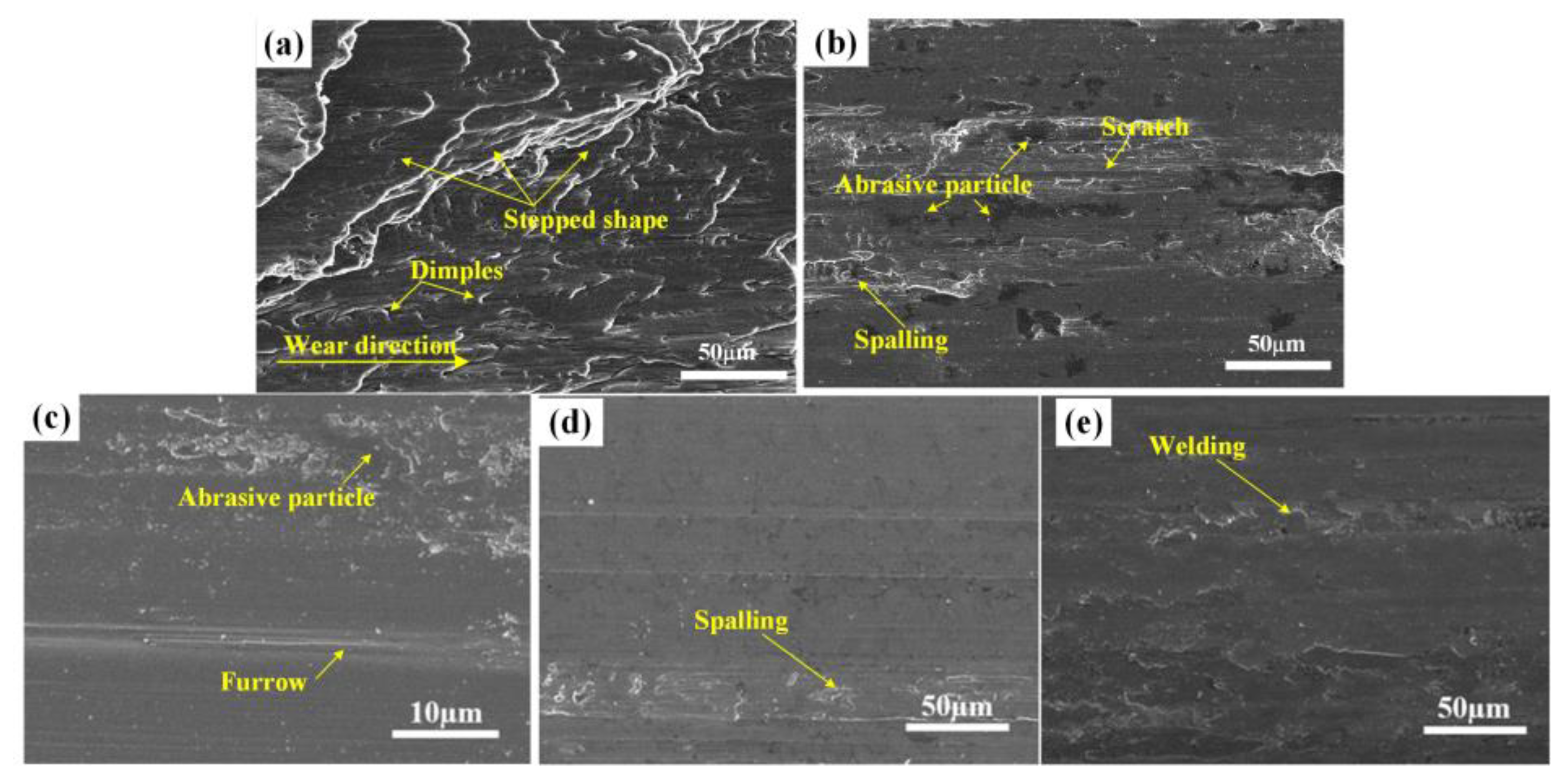
3.4. Friction and Wear Properties

Figure 6 shows the friction coefficient of Al0.8FeCrCoNiCu0.5Yx HEA coatings. Table 2 shows the measured and calculated results of wear length, wear width and wear rate. In the initial wear stage, the GCr15 steel ring is mainly in point and line contact with the wear surface, resulting in an unstable friction coefficient. The specimen is in a stable wear stage after about 10 min. The friction coefficient curves of the samples showed a decreasing trend. When the friction coefficient region was stabilized, the friction coefficient of Y0.05 was close to that of Y0.1. The friction coefficients of Y0 and Y0.2 were slightly higher than the former. The friction coefficient of each coating is 0.551~0.561, which is smaller than the substrate. The wear rate of Al0.8FeCrCoNiCu0.5Yx HEA coatings is significantly smaller than that of the substrate, the wear rate of Y0.05 and Y0.1 is not much different, and the wear rate of Y0.2 is slightly higher. Compared to Al, Y content added to 0.1 reduces the wear rate by 25.8%.
Figure 7 shows the worn surface morphology of the coatings and substrate. The wear surface of each coating is smoother than that of the substrate. The stepped shape and dimple occur on the aluminium, and the wear forms are plastic deformation and fatigue wear, as shown in Figure 7a. On the step-like wear surface, a large number of tough nests appear for the following reasons: on the aluminum alloy surface in the friction and wear process, along the friction block shear stress direction, a large degree of ductile deformation occurred, and the material fractured under continuous shear. Part of the elongated ductile surface was torn shrinkage, forming tough nests. The newly generated surface and friction block contact, continued to cycle the above process, forming step-like fracture.
Y0 showed scratches and spalling, as shown in Figure 7b. This means that the coating surface experienced adhesive wear and, simultaneously, a delamination fracture occurred. The formation of delamination fracture is caused by the material strength is less than the friction sub-shear strength. As the test proceeds, cracks appear on the surface of the specimen under the action of shear, leading to the accumulation of internal dislocations in the material. At this time, the cracks extend along the surface of the test piece gradually appear, and finally in the whole piece off. The large pieces that fall off will significantly increase the wear rate of the material.
The wear surface of Y0.05 has abrasive particles and furrows, which are adhesive wear and abrasive wear, as shown in Figure 7c. This is due to the local stress that causes the welding of the contact area between the counter-abrasive and the micro-bump, and the weld area is torn under the shear stress and reciprocal motion to form spalling pits. The flaking metal particles produce micro-cutting to the coating forming grooves and furrows, indicating that the wear mechanism of the coating is adhesive wear and abrasive wear. Because the Y0 surface hardness is lower, the friction force is most concentrated at the center of the cross-section during the wear process, and the abrasive particles formed during the wear process are easily pressed into the coating surface, leading to material loss and plastic deformation on the coating surface.
As shown in Figure 7d, there is a small peeling surface on the surface of Y0.1, but the furrow is shallow, and the wear mechanism is the same as that of Y0.05. This indicates a higher stacking layer error performance of the Y0.1 [33]. As shown in Figure 7e, Y0.2 has a large welding area. Under the repeated action of the friction pair pressure, the edge of the wear surface of the coating appears to be tilted to a certain extent, the wear groove has undergone plastic deformation, and the appearance of the flocculent structure indicates that the alloy has experienced an oxidation reaction during the wear process. The wear surface of Y0.2 is rougher than that of Y0.1.

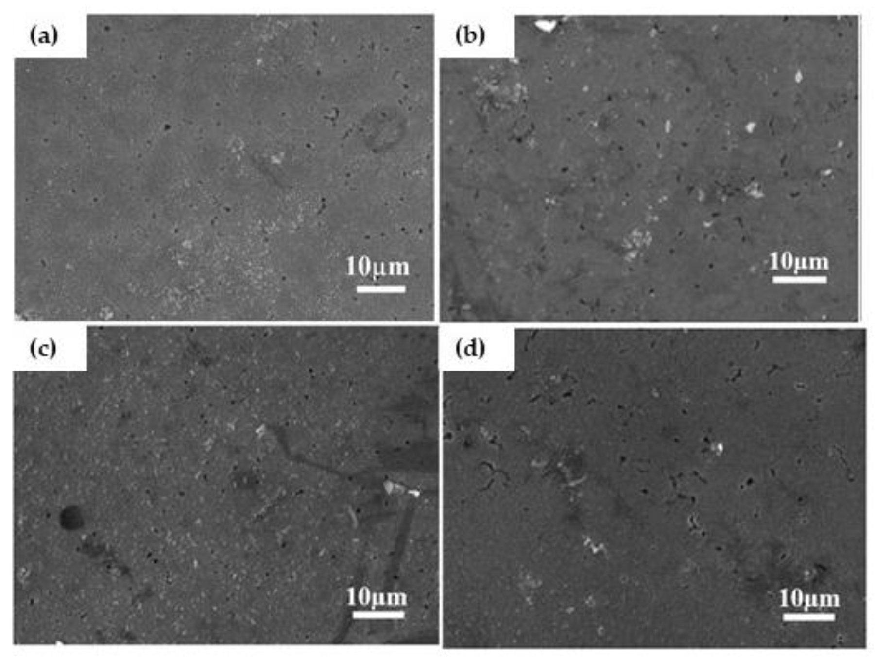
3.5. Corrosion Resistance

Figure 8 shows the polarization curve of coatings and substrate in 3.5% NaCl solution. The coating polarization curve consists of four parts: a cathodic polarization zone, an anodic dissolution zone, a passivation zone, and an over-passivation zone. The passivation zone appears in each specimen, indicating that as the electrochemical corrosion process proceeds, a passivation film will appear on the electrode surface, which can slow down the erosion of Cl ions on the working electrode surface during the electrochemical corrosion process. In the activation-passivation stage, the current density of the sample gradually decreases with the potential increase because the adhesion of corrosion products in this stage hinders the further reaction of the matrix. In the passivation stage, the current density decreases to a very small value and tends to be stable, which indicates that the sample forms a passivation film in the corrosion solution. It is generally believed that the passive film formed by metal in the medium is an oxide or hydroxide, which can keep the anodic dissolution rate of metal at a small value. The protective effect of the passive film on the substrate is related to the integrity, compactness, and uniformity of the passive film.
The polarization curves of all coatings show passivation intervals. Y0.1 has the widest passivation range and Y0.2 has the narrowest passivation range, indicating that the integrity of the passivation film increases first and then decreases with the increase of Y. Table 3 shows the polarization parameters of each sample after Tafel extrapolation fitted the polarization curves. The corrosion current density represents the corrosion resistance rate of the materials. The greater the corrosion current density of materials, the faster the corrosion rate [34]. The corrosion current densities of Y0.05 and Y0.1 s are 6.70 × 10⁻⁸ A/cm2, 9.33 × 10⁻⁷ A/cm2, respectively, at an order of 10−8, smaller than that of Y0.2 and Y0, indicating that the corrosion resistance of Y0.05 and Y0.1 is superior to that of Y0.2 and Y0. As depicted in Figure 8, the corrosion morphology of Al0.8FeCrCoNiCu0.5Yx HEA was examined to investigate its corrosion behavior further.
Figure 9 shows the corrosion morphology of Al0.8FeCrCoNiCu0.5Yx after the dynamic potential polarization test in 3.5% NaCl. In NaCl solution, the corrosion behavior of the alloy is due to the extremely strong penetration of Cl ions in the solution, which tends to adsorb in the weakest region of the passivation film formation, making the corrosion process occur in the occlusion cell effect and causing the concentrated corrosion of the coating. If the alloy is corroded, it will form corrosion products that can be attached to the alloy surface or in corrosion pits. From Figure 9a,b, it can be seen that the corrosion spots of Y0 and Y0.05 tend to be distributed along the intergranular, but no apparent significant corrosion is formed. Figure 9c is the corrosion morphology of Y0.1. Compared with Y0.05, the corrosion spots are smaller and more dispersed. It is speculated that the increase of Y refines the grains and the refined grain boundary makes the copper-rich phase sparsely distributed, which makes it difficult to form large corrosion pits. From Figure 9d, the corrosion spot area of Y0.2 can be seen to be more significant than that of Y0.1, and the corrosion trajectory of some regions is connected to form intergranular corrosion in a small space. It is speculated that the uneven structure distribution of the coating is caused by the excessive addition of Y, indicating that the excessive addition of Y reduces the corrosion resistance of the coating.

4. Conclusions

(1) When Y content is less than 2, Al0.8FeCrCoNiCu0.5Yx coating presents FCC1, BCC1 and BCC2 phases. When Y is added to 0.2, the coating appears rich in the Y phase. The Y0.05 and Y0.1 coating has finer organization compared to Y0. When Y is increased to 0.2, some grains are further refined, but large solidified grains also appear with grain size uniformity.
(2) The average hardness of Y0.1, Y0.2, and Y0.3 are 517 HV0.2, 532 HV0.2, and 544 HV0.2, respectively. The mechanism of hardness improvement is mainly fine-grain strengthening and solid solution strengthening.
(3) The corrosion surfaces of Y0.05 and Y0.1 have a small number of corrosion spots distributed along the crystal; the corrosion resistance is improved mainly because of the refinement of grain boundaries, reducing the concentration of corrosion-prone phases in the intergranular distribution, but the further addition of Y is not conducive to the improvement of the corrosion resistance of the coating.

Author Contributions

Conceptualization, Y.L. and Y.S.; methodology, Y.L.; validation, H.W. and B.Z.; formal analysis, Y.L.; investigation, Y.L.; resources, H.L.; data curation, Y.L.; writing—original draft preparation, Y.L.; writing—review and editing, Y.L. and Y.S.; visualization, Y.L.; supervision, Y.L and D.L.; project administration, Y.L. and J.W.; and funding acquisition, Y.S. All authors have read and agreed to the published version of the manuscript.

Funding

This study was supported by the university level natural science research project of West Anhui University (Grant Nos. WXZR202116, WGKQ2021068), the Natural Science Research Project of the Anhui Provincial Department of Education (Grant Nos. KJ2021A0947, KJ2020A0626, and KJ2020A0625), the Science and Technology Research Project of the Jilin Provincial Department of Education (Grant Nos. JJKH20210219KJ), the High-level Talents Research Project of West Anhui University (Grant No. WGKQ2021068, WGKQ 201802004), and the Key Research and Development Project of Anhui Province (Grant No. 202104a06020004).

Data Availability Statement

The data that support the findings in this study are available from the author Y.L. upon reasonable request.

Conflicts of Interest

The authors declare no conflict of interest.

References

  1. Yeh, J.W.; Chen, S.K.; Lin, S.J.; Gan, J.Y.; Chin, T.S.; Shun, T.T.; Tsau, C.H.; Chang, S.Y. Nanostructured High-Entropy Alloys with Multiple Principal Elements: Novel Alloy Design Concepts and Outcomes. Adv. Eng. Mater. 2004, 6, 299–303. [Google Scholar] [CrossRef]
  2. Yao, X.; Peng, K.; Chen, X.; Jiang, F.; Wang, K.; Wang, Q. Microstructure and mechanical properties of dual wire-arc additive manufactured Al-Co-Cr-Fe-Ni high entropy alloy. Mater. Lett. 2022, 326, 132928. [Google Scholar] [CrossRef]
  3. Shi, F.K.; Zhang, Q.K.; Xu, C.; Hu, F.Q.; Yang, L.J.; Zheng, B.Z.; Song, Z.L. In-situ synthesis of NiCoCrMnFe high entropy alloy coating by laser cladding. Opt. Laser Technol. 2022, 151, 108020. [Google Scholar] [CrossRef]
  4. Ivanov, I.V.; Emurlaev, K.I.; Kuper, K.E.; Akkuzin, S.A.; Bataev, I.A. Deconvolution-based peak profile analysis methods for characterization of CoCrFeMnNi high-entropy alloy. Heliyon 2022, 8, e10541. [Google Scholar] [CrossRef]
  5. Reunova, K.A.; Astafurova, E.G.; Melnikov, E.V.; Astafurov, S.V.; Panchenko, M.Y.; Moskvina, V.A. Effect of solid-solution treatment on the microstructure and mechanical properties of high-nitrogen FeMnCrNiCo high entropy alloys. IOP Conf. Ser. Mater. Sci. Eng. 2021, 1014, 012047. [Google Scholar] [CrossRef]
  6. Dewangan, S.K.; Mangish, A.; Kumar, S.; Sharma, A.; Ahn, B.; Kumar, V. A review on High-Temperature Applicability: A milestone for high entropy alloys. Eng. Sci. Technol. Int. J. 2022, 35, 101211. [Google Scholar] [CrossRef]
  7. Karimzadeh, M.; Malekan, M.; Mirzadeh, H.; Li, L.; Saini, N. Effects of titanium addition on the microstructure and mechanical properties of quaternary CoCrFeNi high entropy alloy. Mater. Sci. Eng. A 2022, 856, 143971. [Google Scholar] [CrossRef]
  8. Liu, Y.; Xu, T.; Li, G. Research on Wear and Corrosion Resistance of Ni60-WC Coating Fabricated by Laser on the Preheated Copper Alloy. Coatings 2022, 12, 1537. [Google Scholar] [CrossRef]
  9. Sha, M.; Jia, C.; Qiao, J.; Feng, W.; Ai, X.; Jing, Y.A.; Shen, M.; Li, S. Microstructure and Properties of High-Entropy AlxCoCrFe2.7MoNi Alloy Coatings Prepared by Laser Cladding. Met.–Open Access Metall. J. 2019, 9, 1243. [Google Scholar] [CrossRef] [Green Version]
  10. Liu, H.; Gao, W.; Liu, J.; Du, X.; Li, X.; Yang, H. Microstructure and Properties of CoCrFeNiTi High-Entropy Alloy Coating Fabricated by Laser Cladding. J. Mater. Eng. Perform. 2020, 29, 7170–7178. [Google Scholar] [CrossRef]
  11. Zhang, S.; Wu, C.L.; Zhang, C.H.; Guan, M.; Tan, J.Z. Laser surface alloying of FeCoCrAlNi high-entropy alloy on 304 stainless steel to enhance corrosion and cavitation erosion resistance. Opt. Laser Technol. 2016, 84, 23–31. [Google Scholar] [CrossRef]
  12. Na, Y.S.; Lim, K.R.; Chang, H.J.; Kim, J. Effect of Trace Additions of Ti on the Microstructure of AlCoCrFeNi-Based High Entropy Alloy. Sci. Adv. Mater. 2016, 8, 1984–1988. [Google Scholar] [CrossRef]
  13. Zhang, C.; Chen, G.J.; Dai, P.Q. Evolution of the microstructure and properties of laser-clad FeCrNiCoBx high-entropy alloy coatings. Mater. Sci. Technol. 2016, 32, 1666–1672. [Google Scholar] [CrossRef]
  14. Ma, S.G.; Zhang, Y. Effect of Nb addition on the microstructure and properties of AlCoCrFeNi high-entropy alloy. Mater. Sci. Eng. A 2012, 532, 480–486. [Google Scholar] [CrossRef]
  15. He, Y.Z.; Zhang, J.L.; Zhang, H.; Song, G.S. Effects of Different Levels of Boron on Microstructure and Hardness of CoCrFeNiAlxCu0.7Si0.1By High-Entropy Alloy Coatings by Laser Cladding. Coatings 2017, 7, 7. [Google Scholar] [CrossRef] [Green Version]
  16. Cai, Y.; Zhu, L.; Cui, Y.; Shan, M.; Han, J. Fracture and wear mechanisms of FeMnCrNiCo + x(TiC) composite high-entropy alloy cladding layers. Appl. Surf. Sci. 2020, 543, 148794. [Google Scholar] [CrossRef]
  17. Wang, C.; Gao, Y.; Wang, R.; Wei, D.; Cai, M.; Fu, Y. Microstructure of laser-clad Ni60 cladding layers added with different amounts of rare-earth oxides on 6063 Al alloys. J. Alloys Compd. 2018, 740, 1099–1107. [Google Scholar] [CrossRef]
  18. Wang, C.; Gao, Y.; Zeng, Z.; Fu, Y. Effect of rare-earth on friction and wear properties of laser cladding Ni-based coatings on 6063Al. J. Alloys Compd. 2017, 727, 278–285. [Google Scholar] [CrossRef]
  19. Das, A.K. Effect of rare earth oxide additive in coating deposited by laser cladding: A review. Mater. Today Proc. 2022, 52, 1558–1564. [Google Scholar] [CrossRef]
  20. Liang, C.J.; Wang, C.L.; Zhang, K.X.; Liang, M.L.; Xie, Y.G.; Liu, W.J.; Yang, J.J.; Zhou, S.F. Nucleation and strengthening mechanism of laser cladding aluminum alloy by Ni-Cr-B-Si alloy powder based on rare earth control. J. Mater. Process. Technol. 2021, 294, 117145. [Google Scholar] [CrossRef]
  21. Hu, Z.; Zhan, Y.; Zhang, G.; She, J.; Li, C. Effect of rare earth Y addition on the microstructure and mechanical properties of high entropy AlCoCrCuNiTi alloys. Mater. Des. 2010, 31, 1599–1602. [Google Scholar] [CrossRef]
  22. Zhang, L.J.; Zhang, M.D.; Zhou, Z.; Fan, J.T.; Cui, P.; Yu, P.F.; Jing, Q.; Ma, M.Z.; Liaw, P.K.; Li, G.; et al. Effects of rare-earth element, Y.; additions on the microstructure and mechanical properties of CoCrFeNi high entropy alloy. Mater. Sci. Eng. A 2018, 725, 437–446. [Google Scholar] [CrossRef] [Green Version]
  23. Lu, S.F.; Ma, L.; Wang, J.; Du, Y.S.; Li, L.; Zhao, J.T.; Rao, G.H. Effect of configuration entropy on magnetocaloric effect of rare earth high-entropy alloy. J. Alloys Compd. 2021, 874, 159918. [Google Scholar] [CrossRef]
  24. Guo, K.; Gou, G.Q.; Lv, H.; Shan, M.L. Jointing of CFRP/5083 Aluminum Alloy by Induction Brazing: Processing, Connecting Mechanism, and Fatigue Performance. Coatings 2022, 12, 1559. [Google Scholar] [CrossRef]
  25. Zhang, P.; Liu, Z.H.; Yue, X.J.; Wang, P.H.; Zhai, Y.C. Water jet impact damage mechanism and dynamic penetration energy absorption of 2A12 aluminum alloy. Vacuum 2022, 206, 111532. [Google Scholar] [CrossRef]
  26. Lv, B.J.; Wang, S.; Xu, T.W.; Guo, F. Effects of minor Nd and Er additions on the precipitation evolution and dynamic recrystallization behavior of Mg-6.0Zn-0.5Mn alloy. J. Magnes. Alloy. 2021, 9, 840–852. [Google Scholar] [CrossRef]
  27. Li, Y.; Shi, Y.; Olugbade, E. Microstructure, mechanical, and corrosion resistance properties of Al0.8CrFeCoNiCux high-entropy alloy coatings on aluminum by laser cladding. Mater. Res. Express 2020, 7, 026504. [Google Scholar] [CrossRef]
  28. Zhang, B.Y.; Wang, Z.T.; Yu, H.; Ning, Y.Q. Microstructural origin and control mechanism of the mixed grain structure in Ni-based superalloys. J. Alloys Compd. 2022, 900, 163515. [Google Scholar] [CrossRef]
  29. Cui, C.; Wu, M.; Miao, X.; Zhao, Z.; Gong, Y. Microstructure and corrosion behavior of CeO2/FeCoNiCrMo high-entropy alloy coating prepared by laser cladding. J. Alloys Compd. 2022, 890, 161826. [Google Scholar] [CrossRef]
  30. Arif, Z.U.; Khalid, M.Y.; ur Rehman, E.; Ullah, S.; Atif, M.; Tariq, A. A review on laser cladding of high-entropy alloys, their recent trends and potential applications. J. Manuf. Process. 2021, 68, 225–273. [Google Scholar] [CrossRef]
  31. Zhang, P.; Liu, J.L.; Gao, Y.R.; Liu, Z.H.; Mai, Q.Q. Effect of heat treatment process on the micro machinability of 7075 aluminum alloy. Vacuum 2023, 207, 111574. [Google Scholar] [CrossRef]
  32. Zhang, P.; Liu, Z.; Liu, J.; Yu, J.; Mai, Q.; Yue, X. Effect of aging plus cryogenic treatment on the machinability of 7075 aluminum alloy. Vacuum 2023, 208, 111692. [Google Scholar] [CrossRef]
  33. Liu, Y.; Li, Z.; Li, G.; Tang, L. Friction and wear behavior of Ni-based alloy coatings with different amount of WC–TiC ceramic particles. J. Mater. Sci. 2023, 58, 1116–1126. [Google Scholar] [CrossRef]
  34. Chou, Y.L.; Yeh, J.W.; Shih, H.C. The effect of molybdenum on the corrosion behaviour of the high-entropy alloys Co1.5CrFeNi1.5Ti0.5Mox in aqueous environments. Corros. Sci. 2010, 52, 2571–2581. [Google Scholar] [CrossRef]
  35. Li, Y.; Shi, Y. Phase assemblage and properties of laser cladded TixCrFeCoNiCu high-entropy alloy coating on aluminum. Mater. Res. Express 2020, 7, 036519. [Google Scholar] [CrossRef]
Figure 1. The schematic diagram of coaxial laser cladding.
Lubricants 11 00050 g001
Figure 2. Schematic diagram of the wear test.
Lubricants 11 00050 g002
Figure 3. XRD of Al0.8FeCrCoNiCu0.5Yx coating.
Lubricants 11 00050 g003
Figure 4. A typical microstructure of the Al0.8FeCrCoNiCu0.5Yx HEA coatings ((a) is the microstructure of Y0; (b) is the microstructure of Y0.05; (c) is the microstructure of Y0.1; (d) is the microstructure of Y0.2).
Lubricants 11 00050 g004
Figure 5. The average hardness of the Al0.8FeCrCoNiCu0.5Yx HEA coatings.
Lubricants 11 00050 g005
Figure 6. Comparison of friction coefficient of the Al0.8FeCrCoNiCu0.5Yx HEA coatings.
Lubricants 11 00050 g006
Figure 7. Typical microstructure of the Al0.8FeCrCoNiCu0.5Yx HEA coatings: ((a) worn surface of substrate; (b) worn surface of Y0; (c) worn surface of Y0.05; (d) worn surface of Y0.1; (e) worn surface of Y0.2).
Lubricants 11 00050 g007
Figure 8. Potentiodynamic polarization curves of the Al0.8FeCrCoNiCu0.5Yx HEA coating and substrate in 3.5% NaCl solution.
Lubricants 11 00050 g008
Figure 9. SEM images of coatings after potentiodynamic polarization:in 3.5% NaCl solution. (a) is the corrosion morphology of Y0; (b) is the corrosion morphology of Y0.05; (c) is the corrosion morphology of Y0.1; (d) is the corrosion morphology of Y0.2.
Lubricants 11 00050 g009
Table 1. Nominal components of Al0.8FeCoNiCrCu0.5Yx (at%).
AlloyAbbreviationAlCrFeCoNiCuY
Al0.8FeCrCoNiCu0.5Y015.8419.8019.8019.8019.804.950
Al0.8FeCrCoNiCu0.5Y0.05Y0.0514.9518.6918.6918.6918.699.340.93
Al0.8FeCrCoNiCu0.5Y0.1Y0.114.8118.5118.5118.5118.519.251.85
Al0.8FeCrCoNiCu0.5Y0.2Y0.214.5418.1818.1818.1818.189.093.63
Table 2. The measured results of wear scar and the calculation results of the wear coefficient.
AlloyLength
(mm)
Width
(mm)
Wear Coefficient
(mm3/Nm)
Substrate7.0014.003.50 × 10−4
Al0.8FeCrCoNiCu0.56.724.825.45 × 10−6
Al0.8FeCrCoNiCu0.5Y0.056.723.493.95 × 10−6
Al0.8FeCrCoNiCu0.5Y0.16.683.524.04 × 10−6
Al0.8FeCrCoNiCu0.5Y0.27.004.328.65 × 10−6
Table 3. The electrochemical parameters of coatings and substrate in 3.5% NaCl solution.
SolutionSamplesEcorr
(V)
Icorr
(A/cm2)
Substrate [35]−1.324.12 × 10−5
3.5% NaClAl0.8FeCrCoNiCu0.5−0.3611.67 × 10−7
Al0.8FeCrCoNiCu0.5Y0.05−0.3368.70 × 10−8
Al0.8FeCrCoNiCu0.5Y0.1−0.3286.33 × 10−8
Al0.8FeCrCoNiCu0.5Y0.2−0.2981.54 × 10−7
Disclaimer/Publisher’s Note: The statements, opinions and data contained in all publications are solely those of the individual author(s) and contributor(s) and not of MDPI and/or the editor(s). MDPI and/or the editor(s) disclaim responsibility for any injury to people or property resulting from any ideas, methods, instructions or products referred to in the content.

