Article

The Partial Derivative Method for Dynamic Stiffness and Damping Coefficients of Supercritical CO2 Foil Bearings

1
Institute of Engineering Thermophysics, Chinese Academy of Sciences, Beijing 100190, China
2
School of Engineering Science, University of Chinese Academy of Sciences, Beijing 100049, China
3
School of Mechanical Engineering, Shenyang University, Shenyang 110044, China
*
Author to whom correspondence should be addressed.
Lubricants 2022, 10(11), 307; https://doi.org/10.3390/lubricants10110307
Submission received: 29 September 2022 / Revised: 3 November 2022 / Accepted: 8 November 2022 / Published: 13 November 2022
(This article belongs to the Special Issue State-of-the-Art of Tribology in China)

Abstract

:
Supercritical CO2 foil bearings are promising bearing technology for supercritical CO2 high-speed turbomachinery. The partial derivative method including complete variable perturbation of the compressible turbulent lubrication Reynolds equation is effective to predict the frequency dependent dynamic stiffness and damping coefficients of supercritical CO2 bearings. In this research, the structural perturbation of foil dynamic model was introduced into this method and then the dynamic coefficients of supercritical CO2 foil bearings were calculated. The results of parametric analysis show that the structural loss factor has little influence on the trend of dynamic coefficients changing with the dimensionless support stiffness but mainly affects the value of stiffness coefficients as well as damping coefficients. Due to the turbulence effect, the bearing number is not able to directly determine the characteristics of supercritical CO2 foil bearings, which is different from air bearings. Compared to the bearing number, the influence of the average Reynolds number on the change of dynamic coefficients with dimensionless support stiffness is more obvious.

1. Introduction

The supercritical carbon dioxide closed-loop Brayton cycle is a promising power generation system due to compact structure and high efficiency [1,2,3]. The characters of high parameters and high efficiency of supercritical CO2 turbomachinery require the rotor with high speed, which makes the bearing technology attract a lot of attentions [4,5]. Supercritical CO2 lubricated bearings can simplify the rotor structure to improve its dynamics as well as eliminate the pollution of lubricant oil completely [6,7,8]. The compliant foil gas bearing technology from Capstone was used in the tests of supercritical CO2 power system in Sandia, which is one of the key technologies of turbo-alternator-compressor configuration [9]. Some of other successful supercritical CO2 turbomachinery test projects also used the foil bearings [1,10].
At present, there are many research studies on the air foil bearing were published, including both mechanism analysis [11,12,13] and prototype test [14,15]. Although the foil bearings lubricated by both supercritical CO2 and air belong to compressible fluid lubrication, their lubricating mechanisms are essentially different because the compressive behavior of supercritical CO2 shows a real gas effect and the turbulence exists in the supercritical CO2 bearing clearances [16]. Conboy developed a model for supercritical CO2 foil thrust bearing based on Reynolds equation considering turbulence and real gas effect [17]. Munroe used COMSOL for the multiphysics field analysis of supercritical CO2 foil thrust bearings [18]. Kim proposed an analysis tool for three-dimensional thermal fluid analysis of radial foil bearings with turbulence and real gas effects [19]. These studies mentioned above only related to the static characteristics of supercritical CO2 foil bearings.
However, the theoretical calculation and design approach to supercritical CO2 foil bearings are still deficient because the dynamic characteristics of bearings are the only basis in the simulation on dynamics of rotor-bearing system [20,21]. For the bearings lubricated with compressible fluid, their dynamic stiffness and damping coefficients change with the perturbation frequency [22]. Chapman recognized the importance of subsynchronous perturbation and derived subsynchronous dynamic coefficients of supercritical CO2 hydrostatic foil bearings by CFD [23]. However, the CFD-based method makes it difficult to consider the dynamical structural deformation of foil. Bi presented the partial derivative method embracing dynamical variations of complete variables in the Reynolds equation for solving the dynamic coefficients of supercritical CO2 rigid cylindrical bearings under different perturbation frequencies [24].
In this paper, the complete variables perturbed partial derivative method given in Ref. [24] is furthered by introducing the structural perturbation theory for the dynamic model of foil. Then, the method is able to calculate the frequency dependent dynamic stiffness and damping coefficients of supercritical CO2 foil bearings with consideration of dynamical deformation of the foil. The calculation model for foil bearing in this study was verified by comparing with the experimental and numerical results in the literature. Under different perturbation frequencies, the influences of foil support stiffness, structural loss factor, bearing number, and average Reynolds number on the dynamic coefficients of supercritical CO2 foil bearing are investigated in detail.

2. Mathematics for Dynamic Coefficients of Supercritical CO2 Foil Bearings

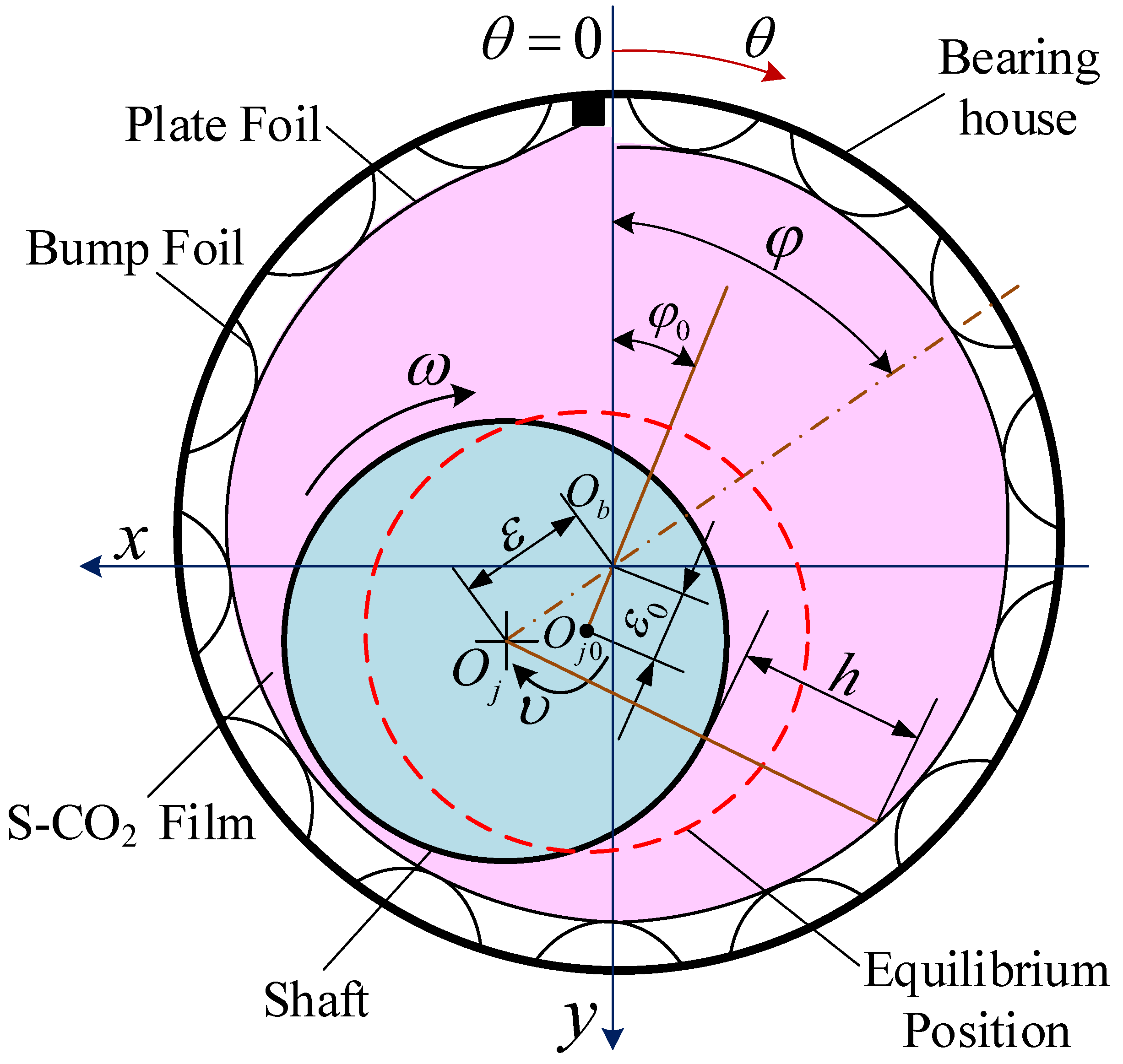
2.1. Supercritical CO2 Lubricated Foil Bearing

The schematic diagram of supercritical CO2 foil bearing studied in this paper is shown in Figure 1. The foil bearing is composed of plate foil, bump foil, and bearing house. In circumferential direction, one end of the two kinds of foil is fixed on the bearing house and the other end is free.
The shaft rotate with angular velocity ω in the foil bearing from free end to fixed end at its equilibrium position described by eccentricity ratio ε0 and attitude angle φ0. The thickness of lubricating film h is the distance between the shaft surface and the inner surface of the plate foil, under the perturbation in the small neighborhood of equilibrium position; its dimensionless form is composed of the static film thickness h ¯ 0 and the perturbed one h ˜ d .
h ¯ = h ¯ 0 + h ˜ d e i Ω t ¯
where Ω is dimensionless perturbation frequency, which equals the ratio of the perturbation circular frequency υ to the rotating circular frequency ω of the shaft. The h ¯ 0 and h ˜ d of the fixed pad bearing with rigid surface can be determined directly by the geometric and kinematic relationship between the shaft and pad. However, the h ¯ 0 and h ˜ d of the foil bearings need to be determined by introducing the structural perturbation (see Section 2.2.1) which reflects the relation between the dynamical deformation and pressure.

2.1.1. The Compressible Turbulence Reynolds Equation and Its Boundary Conditions

The dimensionless compressible turbulent lubrication Reynolds equations including real gas effect for supercritical CO2 bearings were obtained by the partial derivative method in [24] and are shown as follows.
θ ( ρ ¯ 0 h ¯ 0 3 μ ¯ 0 G x p ¯ 0 θ ) + λ ( ρ ¯ 0 h ¯ 0 3 μ ¯ 0 G z p ¯ 0 λ ) = Λ ( ρ ¯ 0 h ¯ 0 ) θ
θ ρ ¯ 0 h ¯ 0 3 μ ¯ 0 G x p ˜ d θ + λ ρ ¯ 0 h ¯ 0 3 μ ¯ 0 G z p ˜ d λ + 1 β 1 θ ¯ p ρ p 0 , T ρ ¯ 0 μ ¯ 0 ¯ p μ p 0 , T h ¯ 0 3 μ ¯ 0 p ¯ 0 θ G x p ˜ d + 1 β 2 λ ¯ p ρ p 0 , T ρ ¯ 0 μ ¯ 0 ¯ p μ p 0 , T h ¯ 0 3 μ ¯ 0 p ¯ 0 λ G z p ˜ d = β 1 3 θ ρ ¯ 0 h ¯ 0 2 μ ¯ 0 p ¯ 0 θ G x h ˜ d + β 2 3 λ ρ ¯ 0 h ¯ 0 2 μ ¯ 0 p ¯ 0 λ G z h ˜ d + Λ θ h ¯ 0 ¯ p ρ p 0 , T p ˜ d + ρ ¯ 0 h ˜ d + 2 i Ω Λ h ¯ 0 ¯ p ρ p 0 , T p ˜ d + ρ ¯ 0 h ˜ d
The static Equation (2) is for static pressure distribution p ¯ 0 and the perturbed Equation (3), which involves the dynamical variations of density, viscosity and the turbulence, governs the perturbed pressure p ˜ d for obtaining the dynamic coefficients. For the foil bearings, the structural perturbation reflects the relation between the p ˜ d and h ˜ d .
In the Equations (2) and (3), the dimensionless turbulent lubrication coefficients Gx and Gz are shown below.
G x = ( 1 + α 1 / 12 R e β 1 ) 1 = ( 1 + 0.0136 / 12 R e 0.9 ) 1 G z = ( 1 + α 2 / 12 R e β 2 ) 1 = ( 1 + 0.0043 / 12 R e 0.96 ) 1
The values of the constants α1, α2, β1, and β2 in the Equation (4) are given by the Ng-Pan turbulence model, which is reasonable for supercritical CO2 bearings [25].
The boundary conditions for the supercritical CO2 foil bearings are absolutely same to the ones which are appropriate for the air foil bearings. The boundary conditions for Equations (2) and (3) are shown below.
p ¯ 0 ( θ , λ = ± L / D ) = p ¯ 0 ( θ = 0 , λ ) = 1 p ˜ d ( θ , λ = ± L / D ) = p ˜ d ( θ = 0 , λ ) = 0
Due to large flexibility, the plate foil is not able to bear the pressure lower than ambient pressure. The Reynolds boundary condition Equation (6), governing the separation of the plate foil from the bump foil, should be supplied to the simulation of the foil bearings.
i f     p ¯ 0 _ t r e n d ( θ , λ ) < 1 { p ¯ 0 ( θ , λ ) = 1 ,       p ¯ 0 θ = 0 p ˜ d ( θ , λ ) = 0 ,       p ˜ d θ = 0

2.1.2. The Damped Elastic Support Comprehensive Dynamic Model for Foil System

The hydrodynamic lubricating film is generated by relative motion of the shaft and the inner surface of the plate foil. As shown in Figure 2, the foil system can be modeled as the acting surface of hydrodynamic lubrication with damped elastic support.
The comprehensive foil model containing elastic support and structure damping is given below.
p p a = k w t + c f w t t
where the wt is the displacement of plate foil. The p-pa is the force onto the foil, which is generated by the pressure difference between the hydrodynamic pressure of the lubricating film and the ambient pressure. The k and cf are the support stiffness and structure damping of the damped elastic support system equivalent to the foil.
Taking the dimensionless pressure p ¯ = p / p a , dimensionless plate foil displacement w ¯ t = w t / C 0 and dimensionless time t ¯ = ω t into Equation (7), the dimensionless dynamic equation for the foil system can be obtained.
p ¯ 1 = k ¯ w ¯ t + c ¯ f w ¯ t t ¯
where the dimensionless support stiffness k ¯ and dimensionless structure damping c ¯ f are as follows.
k ¯ = C 0 p a k c ¯ f = ω C 0 p a c f
The structure damping c f depends on the interaction among the plate foil, bump foil and bearing house, which can be described by the structural loss factor γ based on its relationship with the excitation frequency υ f and the support stiffness k. The structure loss factor γ can be determined by energy dissipation extracted from the dynamical loaded test; its value range is between 0.2 and 0.4 in [26] while Rubio [27] measured values between 0.06 and 0.21.
γ = c f k υ f = c ¯ f k ¯ υ f ω
Pronobis pointed out that the excitation frequency υ f should be equal to the shaft rotation frequency ω rather than the shaft perturbation frequency υ , because the deformation speed of the foil under the instability critical state is equal to the rotation speed of the shaft [28]. The instability rotation speed calculated by the eigenvalue method is consistent with the transient dynamic calculation as long as the υ f / ω = 1 is satisfied. Taking Equation (10) into Equation (8), the dimensionless foil dynamic equation can be obtained as follow.
p ¯ 1 k ¯ = w ¯ t + γ w ¯ t t ¯

2.2. The Structural Perturbation Theory of Foil Bearings

2.2.1. The Relation between the Perturbation of Foil Displacement and Perturbed Pressure

The dynamical variation of the displacement of plate foil w ¯ t is expressed as the superposition of the static displacement w ¯ t 0 and the perturbed displacement w ˜ t .
w ¯ t = w ¯ t 0 + w ˜ t e i Ω t ¯
Considering the dynamical displacement of plate foil, the static film thickness h ¯ 0 and the perturbed film thickness h ˜ d are shown as follows.
h ¯ 0 = h ¯ J 0 + w ¯ t 0 = 1 + ε 0 cos ( θ φ 0 ) + w ¯ t 0
h ˜ d = h ˜ J d + w ˜ t = ε ˜ d cos ( θ φ 0 ) + ε 0 φ ˜ d sin ( θ φ 0 ) + w ˜ t
The expressions of w ¯ t 0 and w ˜ t require to be obtained by perturbing the damped elastic support model of the foil system. Taking the perturbation expansions of foil displacement Equation (12) and pressure ( p ¯ = p ¯ 0 + p ˜ d e i Ω t ¯ ) into the dimensionless foil dynamic Equation (11), the zero order and first order terms are separated and then the structural perturbation of foil bearings is obtained below.
w ¯ t 0 = p ¯ 0 1 k ¯
w ˜ t = p ˜ d k ¯ ( 1 + i Ω γ )
Equation (15) is the relation between the static plate foil displacement w ¯ t 0 and static pressure p ¯ 0 , while Equation (16) is the relation between the perturbed foil displacement w ˜ t and perturbed pressure p ˜ d . The damped elastic support foil dynamic model was modeled as dynamical complex stiffness k ¯ ( 1 + i Ω γ ) , which expresses the elastic support and structure damping together by the superposition of the static support stiffness (real part) and perturbed stiffness (imaginary part).

2.2.2. The Partial Differential Equations for Complex Perturbed Pressure

Taking Equation (16) into Equation (14), the expression of perturbed film thickness h ˜ d can be obtained below.
h ˜ d = ε ˜ d cos ( θ φ 0 ) + ε 0 φ ˜ d sin ( θ φ 0 ) + p ˜ d k ¯ ( 1 + i Ω γ )
Two perturbation variables ε ˜ d and φ ˜ d are involved in Equation (17). Let Pε= p ˜ d / ε ˜ d , Pφ = (1/ε0) ( p ˜ d / φ ˜ d ) , and taking partial derivative of h ˜ d to ε ˜ d and ε 0 φ ˜ d , the Hε and Hφ are defined as Equation (18).
H ε = h ˜ d ε ˜ d = cos ( θ φ 0 ) + P ε k ¯ ( 1 + i Ω γ ) H φ = 1 ε 0 h ˜ d φ ˜ d = sin ( θ φ 0 ) + P φ k ¯ ( 1 + i Ω γ )
In Equation (3), replacing the p ˜ d by Pε, Pφ and the h ˜ d by Hε, Hφ, respectively, yields two partial differential equations for Pε and Pφ, shown as Equations (19) and (20).
θ ρ ¯ 0 h ¯ 0 3 μ ¯ 0 G x P ε θ + λ ρ ¯ 0 h ¯ 0 3 μ ¯ 0 G z P ε λ + 3 β 1 θ ρ ¯ 0 h ¯ 0 2 μ ¯ 0 p ¯ 0 θ G x P ε k ¯ ( 1 + i Ω γ ) + 1 β 1 θ ¯ p ρ p 0 , T ρ ¯ 0 μ ¯ 0 ¯ p μ p 0 , T h ¯ 0 3 μ ¯ 0 p ¯ 0 θ G x P ε + 1 β 2 λ ¯ p ρ p 0 , T ρ ¯ 0 μ ¯ 0 ¯ p μ p 0 , T h ¯ 0 3 μ ¯ 0 p ¯ 0 λ G z P ε + 3 β 2 λ ρ ¯ 0 h ¯ 0 2 μ ¯ 0 p ¯ 0 λ G z P ε k ¯ ( 1 + i Ω γ ) = β 1 3 θ ρ ¯ 0 h ¯ 0 2 μ ¯ 0 p ¯ 0 θ G x cos θ φ 0 + β 2 3 λ ρ ¯ 0 h ¯ 0 2 μ ¯ 0 p ¯ 0 λ G z cos θ φ 0 + Λ θ ρ ¯ 0 P ε k ¯ ( 1 + i Ω γ ) + 2 i Ω Λ ρ ¯ 0 P ε k ¯ ( 1 + i Ω γ ) + Λ θ + 2 i Ω h ¯ 0 ¯ p ρ p 0 , T P ε + ρ ¯ 0 cos θ φ 0
θ ρ ¯ 0 h ¯ 0 3 μ ¯ 0 G x P φ θ + λ ρ ¯ 0 h ¯ 0 3 μ ¯ 0 G z P φ λ + 3 β 1 θ ρ ¯ 0 h ¯ 0 2 μ ¯ 0 p ¯ 0 θ G x P φ k ¯ ( 1 + i Ω γ ) + 1 β 1 θ ¯ p ρ p 0 , T ρ ¯ 0 μ ¯ 0 ¯ p μ p 0 , T h ¯ 0 3 μ ¯ 0 p ¯ 0 θ G x P φ + 1 β 2 λ ¯ p ρ p 0 , T ρ ¯ 0 μ ¯ 0 ¯ p μ p 0 , T h ¯ 0 3 μ ¯ 0 p ¯ 0 λ G z P φ + 3 β 2 λ ρ ¯ 0 h ¯ 0 2 μ ¯ 0 p ¯ 0 λ G z P φ k ¯ ( 1 + i Ω γ ) = β 1 3 θ ρ ¯ 0 h ¯ 0 2 μ ¯ 0 p ¯ 0 θ G x sin θ φ 0 + β 2 3 λ ρ ¯ 0 h ¯ 0 2 μ ¯ 0 p ¯ 0 λ G z sin θ φ 0 + Λ θ ρ ¯ 0 P φ k ¯ ( 1 + i Ω γ ) + 2 i Ω Λ ρ ¯ 0 P φ k ¯ ( 1 + i Ω γ ) + Λ θ + 2 i Ω h ¯ 0 ¯ p ρ p 0 , T P φ + ρ ¯ 0 sin θ φ 0
The dynamic coefficients of the supercritical CO2 foil bearing based on the equations above include the coupling perturbations of the complete variables in the compressible turbulent lubrication Reynolds equation and the dynamic model of foil.
The complex pressure distributions Pε and Pφ were solved numerically by finite difference method. Then, the dynamic coefficients in the coupled coordinate system of x-y and ε-φ are obtained by numerical integration below.
R L L 2 R L 2 R 0 2 π P ε sin θ d θ d λ = k x ε + i Ω c x ε R L L 2 R L 2 R 0 2 π P ε cos θ d θ d λ = k y ε + i Ω c y ε R L L 2 R L 2 R 0 2 π P φ sin θ d θ d λ = k x φ + i Ω c x φ R L L 2 R L 2 R 0 2 π P φ cos θ d θ d λ = k y φ + i Ω c y φ
The dynamic coefficients in the x-y Cartesian coordinate system shown in Figure 1 can be obtained by the transformation below.
[ k x x k x y ] = [ A ] [ k x ε k x φ ] = [ sin φ 0 cos φ 0 cos φ 0 sin φ 0 ] [ k x ε k x φ ] [ k y x k y y ] = [ A ] [ k y ε k y φ ] ; [ c x x c x y ] = [ A ] [ c x ε c x φ ] ; [ c y x c y y ] = [ A ] [ c y ε c y φ ]
where the [ A ] is rotation matrix.

3. Numerical Results and Discussion

3.1. Program Verification

In order to verify the calculation program in this paper, the Reynolds equation for the supercritical carbon dioxide lubricating film was regressed and then used for air foil bearing. The calculation results of the minimum air film thickness are compared with the experimental results published in [29] and the numerical results with FEM foil model [30]. The structure and material parameters of the foil bearing corresponding to the experimental data in the literature are listed in Table 1. Based on these parameters, the Iordanoff formula [31] is used to calculate the support stiffness (per unit area) of the uniform linear spring, the value of which is 1.04 × 10¹⁰ N/m3.
Figure 3a,b show the comparison of the minimum gas film thickness of the two-dimensional uniform spring model with the results of experiments [29] and simulations [30] at rotating speeds of 30,000 r/min and 45,000 r/min, respectively. The calculation results of the minimum gas film thickness obtained by the program in this paper decrease with the increase of the load, and the variation trend is consistent with the test results. It can be seen that whether it is 30,000 r/min or 45,000 r/min, the calculated result of the minimum air film thickness at the axial middle section of the foil bearing is larger than the experimental result, while the results at the edge are in contrary. This shows that the calculated difference between the midsection and the edge is larger than the test result. The reason is that the support stiffness is evenly distributed along the axial direction during the calculation, and the three-dimensional bending of the bump foil along the axial direction can resist deformation when there is a pressure difference along the axial direction. The discontinuous distribution of bump foil support stiffness is taken into account by Kim TH [30], in which the top foil needs to be modeled by 2D plate elements.

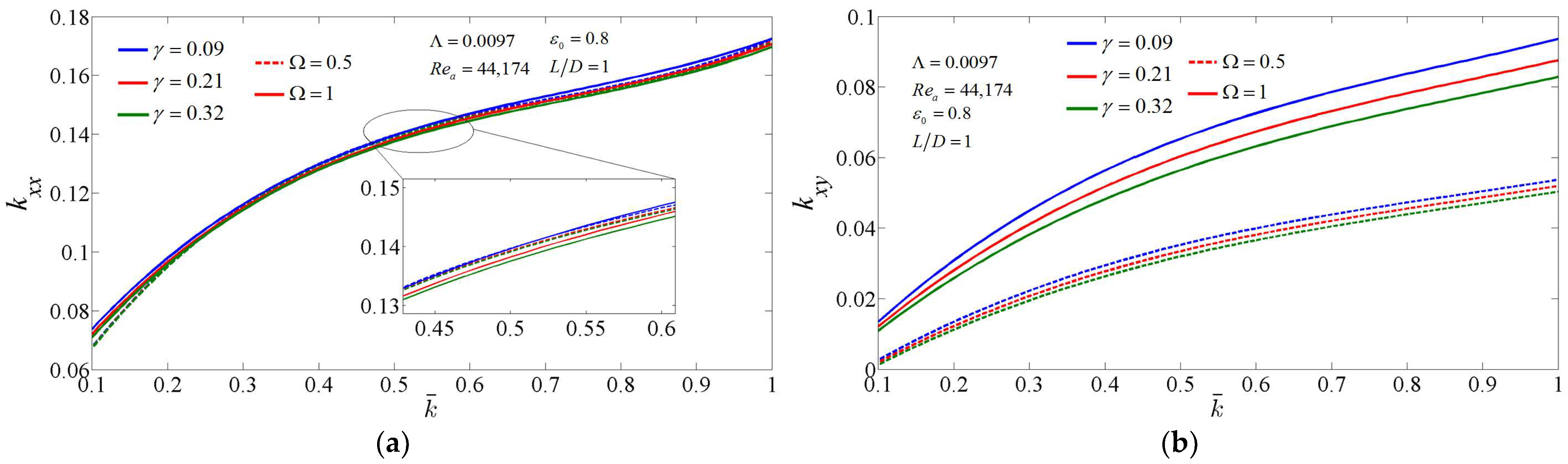
3.2. The Influence of Structural Loss Factor on the Dynamic Coefficients of Supercritical CO2 Foil Bearing

In this Section, and the following Section 3.3 and Section 3.4, the fluid in the lubricating thin film of foil bearing is supercritical CO2. Both the ambient pressure and ambient temperature (pa, Ta) of bearings are higher than and not extremely close to the critical point. The input parameters of foil bearing in this paper are dimensionless, which, related to ambient parameters, includes the bearing number Λ = 6μaω/pa(R/C0)2 and the average Reynolds number Rea = ρaωRC0/μa.
The variations of dynamic stiffness and damping coefficients of supercritical CO2 foil bearing are shown in Figure 4, when eccentricity ε0 is 0.8, bearing number Λ is 0.0097, average Reynolds number Rea is 44,174 and length-to-diameter ratio L/D is 1, respectively. In Figure 4, the structural loss coefficients are 0.09, 0.21, and 0.32, respectively, and the dimensionless perturbation frequencies are 0.5 and 1, respectively.
As k ¯ varies from 0.1 to 1 in Figure 4, dynamic stiffness coefficients increase with the dimensionless bearing stiffness k ¯ . Whether the dimensionless perturbation frequency Ω is 1 or 0.5, the difference among the direct stiffness coefficients kxx under different structural loss factors are small. The direct stiffness coefficients kxx are nearly the same under the dimensionless perturbation frequencies Ω = 1 and 0.5. Whether the dimensionless perturbation frequency Ω is 1 or 0.5, the larger the structural loss factor γ, the smaller the cross-coupling stiffness coefficient kxy. The difference of the cross-coupling stiffness coefficients kxy under different structural loss factors γ varies with the dimensionless support stiffness k ¯ , and the difference increases first and then remains unchanged. When the dimensionless perturbation frequency Ω is 1, the cross-coupling stiffness coefficient kxy is larger than that under the dimensionless perturbation frequency Ω = 0.5. The difference among the cross-coupling stiffness coefficients kxy under different structural loss factors is also in the same regulation. When the dimensionless perturbation frequency Ω is 0.5, the cross-coupling stiffness coefficients kyx under different structural loss factors γ are equal. When the dimensionless perturbation frequency Ω is 1, the difference among the cross-coupling stiffness coefficients kyx under different structural loss factors γ is also small, and the larger the structural loss factor γ, the larger the cross-coupling stiffness coefficient kyx.
For different structural loss factors γ and dimensionless perturbation frequencies Ω in Figure 4, the variation of the direct stiffness coefficient kyy with the dimensionless support stiffness k ¯ is highly similar to the cross-coupling stiffness coefficient kxy, but the difference among the results of the direct stiffness coefficients kyy under different parameters is smaller. Whether the dimensionless perturbation frequency is 1 or 0.5, the larger the structural loss factor γ, the larger the values of the four dynamic damping coefficients. Under the same structural loss factor γ, for the direct damping coefficient cxx and the cross-coupling damping coefficient cyx, the results under dimensionless perturbation frequency Ω = 1 are larger than that under Ω = 0.5. The results of the direct damping coefficient cyy and the cross-coupling damping coefficient cxy when the dimensionless perturbation frequency Ω is 1 are smaller than those when the dimensionless perturbation frequency Ω is 0.5. The effect of the structural loss factor γ on the cxx and cyx is more pronounced than that of the structural loss factor γ on cxy and cyy.
It can be seen that the structural loss factor has influence on the stiffness coefficients as well as the damping coefficients of foil bearing. Such reason is that the dynamic coefficients are determined by the dynamical stiffness of foil support system, which is a complex number, and the structural loss factor is contained in the imaginary part.

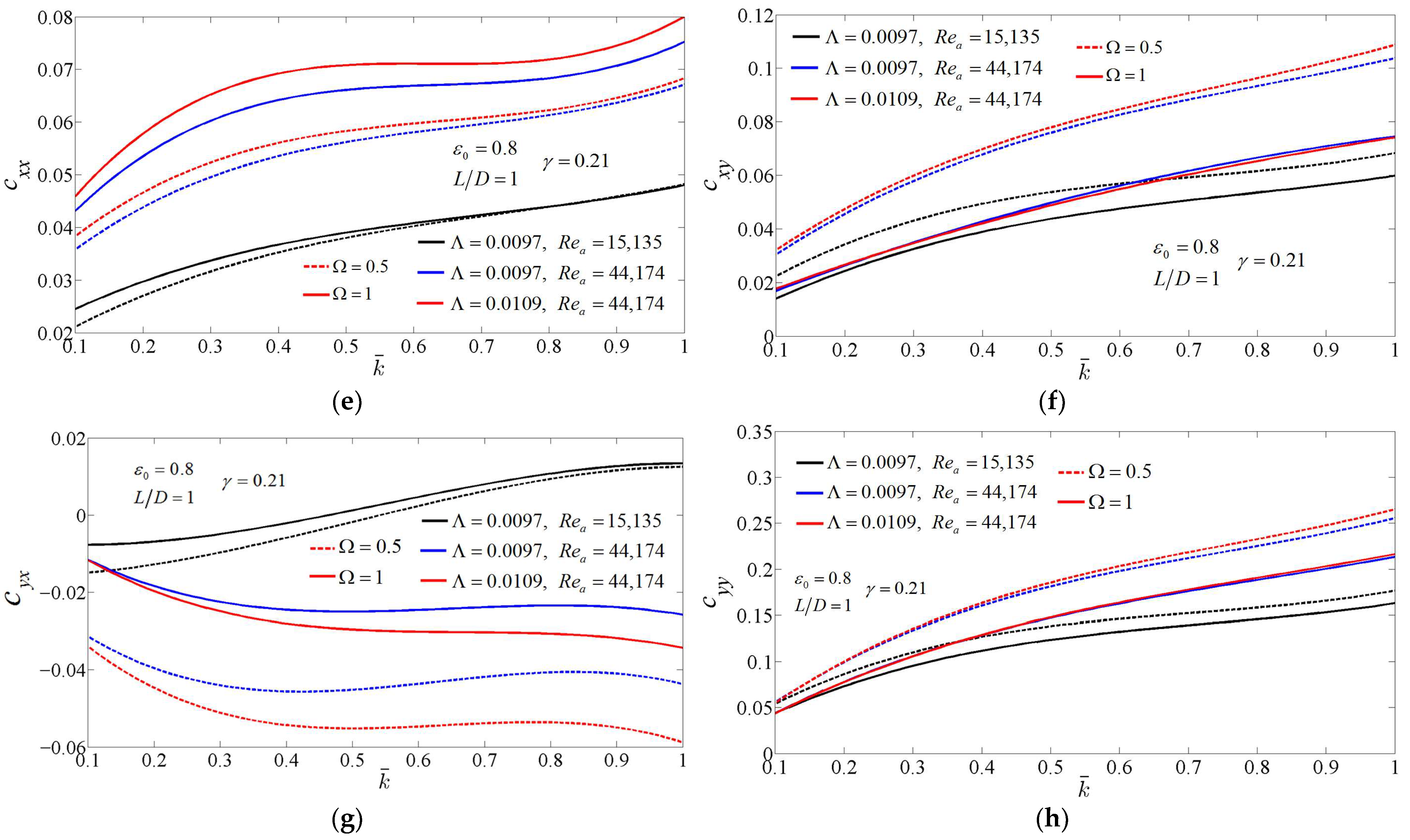
3.3. The Influence of Bearing Number and Average Reynolds Number on the Dynamic Coefficients of Supercritical CO2 Foil Bearing

Dynamic stiffness and damping coefficients of the supercritical CO2 foil bearing are shown in Figure 5 with different bearing numbers Λ and average Reynolds number Rea, when the structural loss factor γ is 0.21, the eccentricity ε0 is 0.8 and the length-to-diameter ratio L/D is 1, and the dimensionless perturbation frequency Ω is 0.5 or 1, respectively, where the results for the blue lines are the same as the input parameters when the structural loss factor γ is 0.21 in Figure 4.
By comparing the results of the red lines and the blue lines, it can be seen that for the same average Reynolds number Rea, the variation of the direct stiffness coefficients with the dimensionless support stiffness k ¯ is nearly the same under different bearing numbers Λ and different dimensionless perturbation frequencies Ω. Similar results are obtained for other stiffness and damping coefficients. Under the same average Reynolds number Rea and dimensionless perturbation frequency Ω, the direct stiffness coefficients kxx and direct damping coefficients cxx at the Λ = 0.0109 are larger than the results at the Λ = 0.0097. However, the cross-coupling damping coefficient cyx at the Λ = 0.0109 is smaller than the results at the Λ = 0.0097. For the cross-coupling stiffness coefficient kxy with dimensionless support stiffness k ¯ < 0.3 and the direct stiffness coefficients kyy with dimensionless support stiffness k ¯ = 0.1, the results at the Λ = 0.0109 are equal to that at the Λ = 0.0097. The results of kxy and kyy under the other dimensionless support stiffness k ¯ and the Λ = 0.0109 are larger than that at the Λ = 0.0097. Under the same average Reynolds number Rea, the dimensionless perturbation frequency Ω = 1 and the dimensionless support stiffness k ¯ < 0.73, the cross-coupling stiffness coefficients kyx at the Λ = 0.0109 are equal to that at the Λ = 0.0097. The cross-coupling stiffness coefficients kyx under the other dimensionless support stiffness k ¯ at the bearing number Λ = 0.0109 is slightly larger than the results at the bearing number Λ = 0.0097. The stiffness coefficients under dimensionless perturbation frequency Ω = 0.5 are similar to those under dimensionless perturbation frequency Ω = 1. Under the same average Reynolds number Rea, when the dimensionless perturbation frequency Ω is 1, the cross-coupling damping coefficient cxy at the bearing number Λ = 0.0109 is nearly the same as the results at the bearing number Λ = 0.0097. When the dimensionless perturbation frequency is 0.5 and the bearing number Λ is 0.0109, the results are slightly larger than those when the bearing number is 0.0097. The variation of the direct damping coefficient cyy with the dimensionless support stiffness k ¯ is similar to that of the cross-coupling damping coefficient cxy.
However, comparing the results of the black lines and the blue lines, at the same bearing number, the variation of bearing stiffness and damping coefficients with the dimensionless support stiffness k ¯ under different average Reynolds numbers Rea and different dimensionless perturbation frequencies Ω have nearly no similarity. Such reason is that both the compressibility and the turbulence effect are included in the average Reynolds number, while the bearing number reflects the compressibility only. Because of the turbulence effect, the bearing number is not able to directly determine the characteris-tics of supercritical CO2 foil bearings, which is different from air bearings.

3.4. The Influence of Compressibility of Supercritical CO2 on the Dynamic Coefficients

The variation of the dynamic stiffness and damping coefficients of supercritical CO2 foil bearing with dimensionless perturbation frequency Ω are shown in Figure 6, when the eccentricity ε0 is 0.6, bearing number Λ is 0.01, average Reynolds number Rea is 49,260, and L/D is 1. The results by the partial derivative method at different conditions of perturbation are shown by different colors in each subplot, with the red lines (CVP) considering the complete variables perturbations, the green lines (QST) and blue lines (OPP) considering quasistatic treatment (without ∂ρ/∂t) and only perturbed pressure, respectively.
The blue line shows that the conventional perturbation method for air bearings indiscriminately applied to supercritical CO2 bearings. The difference between the blue lines and the red lines reflects the perturbation effects of density, viscosity, and Reynolds number. The difference between the green lines and red lines reflects the effect of partial density over partial time (The hysteresis of lubricating film to perturbation caused by compressibility of lubricant).
When the dimensionless perturbation frequency Ω tends to 0+, all the stiffness coefficients of the foil bearing considering the complete variable perturbation are identical to the results of the quasi-static treatment. Because the foil deformation is a static process independent of time under infinitely slow small displacements of the shaft. As the dimensionless perturbation frequency Ω increases, for the direct stiffness coefficient kxx, when Ω is less than 0.4, the results considering the complete variable perturbation are equal to the quasi-static treatment, and decrease with Ω. However, when Ω > 0.4, the results by complete variable perturbation begin to increase while the results by the quasi-static treatment continue to decrease. The direct stiffness coefficient kyy by complete variable perturbation increases significantly with Ω.
In the range of perturbation frequencies Ω in Figure 6, the cross-coupling stiffness kxy by the complete variable perturbation is larger than that by the two degenerate conditions, while the kyx by complete variable perturbation is the smallest. The direct damping cxx by quasi-static treatment is nearly equal to that by only perturbed pressure. The direct damping coefficients and the cross-coupling damping coefficient cyx obtained by complete variable perturbation are significantly smaller than those by the two degenerate conditions. For the cross-coupling damping coefficient cxy, the results by complete variable perturbation are between the two degradation conditions when dimensionless perturbation frequencies Ω is less than 1.1, and less than the two degradation conditions when Ω > 1.1.
Although the time lag effect of the compressible lubrication ∂ρ/∂t can be reflected only by the partial derivative method including complete variable perturbation, all the dynamic coefficients obtained by the two degradation conditions in Figure 6 also vary with the dimensionless perturbation frequency Ω, which is brought about by the structural perturbation of the foil bearing through the ∂h/∂t term. Such indicates that the frequency effect of the dynamic coefficients of compressible lubricated foil bearings is the result of both the properties of lubricant and the dynamical deformation of the foil.

4. Conclusions

In this paper, both the damped elastic support foil model and the compressible turbulent lubrication Reynolds equation were perturbed by the partial derivative method with dynamical variations of complete variables. Then the partial derivative method can be used to solve the stiffness and damping coefficients of supercritical CO2 foil bearings under different perturbation frequencies. The main conclusions are as follows:
  • The results of minimum film thickness of an air foil bearing were calculated by the program of the method of this research (through a simple change) and compared with the test and calculation data in the literature. It is verified that the two-dimensional uniform spring model for support stiffness is reasonable for foil bearings.
  • The partial derivative method is able to take into account the influence of structural loss factor as well as perturbation frequency on the dynamic coefficients of foil bearings. The structural loss factor has influence on the stiffness coefficients as well as the damping coefficients. Thus, for compressible lubricated bearings, the static stiffness and damping coefficients (obtained under perturbation frequency infinitely close to zero) are not the dynamic coefficients required for rotor dynamics analysis. The structural loss factor has little influence on the trend of dynamic coefficients changing with the dimensionless support stiffness, but mainly affects their value.
  • Due to the turbulence effect, the bearing number is not able to directly determine the characteristics of supercritical CO2 foil bearings, which is different from air bearings. For the same average Reynolds number, the trends of stiffness and damping coefficients changing with the dimensionless support stiffness are similar, and the bearing number only affects the value of dynamic coefficients. The average Reynolds number not only affects the values of the dynamic coefficients but also has influence on their variations with the dimensionless support stiffness.

Author Contributions

Conceptualization, C.B. and D.H.; Methodology, C.B.; Data curation, C.B.; Formal analysis, D.H.; Investigation, C.B.; Project administration, D.H.; Software, C.B.; Validation, C.B. and D.H.; Writing—original draft, C.B. and D.H.; Writing—review and editing, C.B. and D.H.; Funding acquisition, D.H. All authors have read and agreed to the published version of the manuscript.

Funding

This work was supported by the Youth Innovation Promotion Association CAS (2021141), and the National Natural Science Foundation of China (Grant No. 11602268).

Data Availability Statement

Not applicable.

Acknowledgments

The authors have to acknowledge Comrade Yao WU (from Shaanxi University of Science & Technology) for his guidance on algorithms and programming design. The authors also gratefully thank for the suggestions and comments from the editors and reviewers.

Conflicts of Interest

The authors declared no conflict of interest with respect to the research, authorship, and publication of this article.

Nomenclature

θcircumferential angular coordinate
εeccentricity ratio
φ attitude angle
Ojshaft center
Obbearing center
hfilm thickness
ωrotational circular frequency
υshaft perturbation circular frequency
Ωdimensionless perturbation frequency
ttime
ρdensity
μviscosity
ppressure
λdimensionless axial coordinate
Λbearing number
Gx, Gzturbulence coefficients
α1, β1, α2, β2constants in the turbulence coefficients
wtdisplacement of plate foil
ksupport stiffness
cfstructure damping
γstructural loss factor
Rbearing radius
Lbearing length
C0radius clearance
Pε, Pφcomplex perturbed pressure
Subscripts
0static variables
dperturbations
aambient parameters
Headers
-dimensionless variables
~complex amplitude of frequency perturbation
Abbreviations
CVPcomplete variables perturbations
QSTquasi-static treatment
OPPonly perturbed pressure

References

  1. Kimball, K.; Clementoni, E. Supercritical carbon dioxide Brayton power cycle development overview. In Proceedings of the ASME Turbo Expo 2012: Turbine Technical Conference and Exposition, Copenhagen, Denmark, 11–15 June 2012. [Google Scholar]
  2. Betti, A.; Forte, P.; Ciulli, E. Turbulence Effects in Tilting Pad Journal Bearings: A Review. Lubricants 2022, 10, 171. [Google Scholar] [CrossRef]
  3. Dostal, V.; Hejzlar, P.; Driscoll, M.J. The Supercritical Carbon Dioxide Power Cycle: Comparison to Other Advanced Power Cycles. Nucl. Technol. 2006, 154, 283–301. [Google Scholar] [CrossRef]
  4. Ertas, B.; Bidkar, R. Apollo High Efficiency sCO2 Centrifugal Compressor Continuation Report, Section 7: Gas Bearing Design and Testing. DOE Contract EE0007109, 16 February 2017.
  5. Mehdi, S.M.; Kim, T.H. Computational Model Development for Hybrid Tilting Pad Journal Bearings Lubricated with Supercritical Carbon Dioxide. Appl. Sci. 2022, 12, 1320. [Google Scholar] [CrossRef]
  6. Thatte, A.; Loghin, A.; Shin, Y.; Ananthasayanam, B. Performance and life characteristics of hybrid gas bearing in a 10 MW supercritical CO2 turbine. In Proceedings of the ASME Turbo Expo 2016: Turbomachinery Technical Conference and Exposition, Seoul, Korea, 13–17 June 2016. [Google Scholar]
  7. Qin, K.; Jahn, I.H.; Gollan, R.; Jacobs, P. Development of a Computational Tool to Simulate Foil Bearings for Supercritical CO2 Cycles. J. Eng. Gas Turbines Power 2016, 138, 092503. [Google Scholar] [CrossRef]
  8. Hacks, A.; Schuster, S.; Dohmen, H.J.; Benra, F.-K.; Brillert, D. Turbomachine design for supercritical carbon dioxide within the sCO2-HeRo. eu project. In Proceedings of the ASME Turbo Expo 2018: Turbomachinery Technical Conference and Exposition, Oslo, Norway, 11–15 June 2018. [Google Scholar]
  9. Wright, S.; Radel, R.; Vernon, M.; Rochau, G.; Pickard, P. Operation and Analysis of a Supercritical CO2 Brayton Cycle; Sandia Report. No. SAND2010-0171; Sandia National Laboratories (SNL): Albuquerque, NM, USA; Livermore, CA, USA, 2010.
  10. Cho, J.; Shin, H.; Ra, H.S.; Lee, G.; Roh, C.; Lee, B.; Baik, Y.J. Development of the Supercritical Carbon Dioxide Power Cycle Experimental Loop in KIER. In Proceedings of the ASME Turbo Expo 2016: Turbomachinery Technical Conference and Exposition, Seoul, Korea, 13–17 June 2016. [Google Scholar]
  11. Li, C.; Du, J.; Li, J.; Xu, Z. Investigations on the Frictional Hysteresis Effect of Multi-Leaf Journal Foil Bearing: Modeling, Predictions and Validations. Lubricants 2022, 10, 261. [Google Scholar] [CrossRef]
  12. Wang, C.; Wang, X.; Hu, Y. Investigation on start-up performance of gas foil bearing considering wear topography evolution of non-Gaussian surface. Tribol. Int. 2023, 177, 108003. [Google Scholar] [CrossRef]
  13. Bou-Saïd, B.; Lahmar, M.; Mouassa, A.; Bouchehit, B. Dynamic Performances of Foil Bearing Supporting a Jeffcot Flexible Rotor System Using FEM. Lubricants 2020, 8, 14. [Google Scholar] [CrossRef] [Green Version]
  14. Li, H.; Geng, H.; Wang, B.; Zheng, W. Feasibility investigation of a compressor rotor supported by gas foil bearings with inhomogeneous bump foils. Proc. Inst. Mech. Eng. Part J J. Eng. Tribol. 2022, 236, 174–183. [Google Scholar] [CrossRef]
  15. Tian, J.; Yang, B.; Feng, S.; Yu, L.; Zhou, J. Investigation of rotor–gas foil bearing system and its application for an ultra-high-speed permanent magnet synchronous motor. Proc. Inst. Mech. Eng. Part J J. Eng. Tribol. 2022, 236, 595–606. [Google Scholar] [CrossRef]
  16. Xu, F.; Kim, D. Three-Dimensional Turbulent ThermoElastohydrodynamic Analyses of Hybrid Thrust Foil Bearings using Real Gas Model. In Proceedings of the ASME Turbo Expo 2016: Turbomachinery Technical Conference and Exposition, Seoul, Korea, 13–17 June 2016. [Google Scholar]
  17. Conboy, T. Real-gas effects in foil thrust bearings operating in the turbulent regime. J. Tribol. 2013, 135, 031703. [Google Scholar] [CrossRef]
  18. Munroe, T.A. COMSOL Multiphysics Predictions of Pressurized CO2 Foil Thrust Bearing Characteristics. In Proceedings of the Supercritical CO2 Power Cycle Symposium, Boulder, CO, Canada, 24–25 May 2011. [Google Scholar]
  19. Kim, D. Design Space of Foil Bearings for Closed-Loop Supercritical CO2 Power Cycles Based on Three-Dimensional Thermohydrodynamic Analyses. J. Eng. Gas Turbines Power 2016, 138, 032504. [Google Scholar] [CrossRef]
  20. Xie, Z.; Jiao, J.; Yang, K.; He, T.; Chen, R.; Zhu, W. Experimental and numerical exploration on the nonlinear dynamic behaviors of a novel bearing lubricated by low viscosity lubricant. Mech. Syst. Signal Process. 2023, 182, 109349. [Google Scholar] [CrossRef]
  21. Han, D.; Bi, C.; Chen, C.; Yang, J. Dynamic Coefficients of Tilting Pad Bearing by Perturbing the Turbulence Model. Appl. Sci. 2022, 12, 6348. [Google Scholar] [CrossRef]
  22. Wu, Y.; Yang, L.; Xu, T.; Wu, W. Thermo-Elasto-Hydrodynamic Characteristics Analysis of Journal Microbearing Lubricated with Rarefied Gas. Micromachines 2020, 11, 955. [Google Scholar] [CrossRef] [PubMed]
  23. Chapman, P.A. Advanced Gas Foil Bearing Design for Supercritical CO2 Power Cycles. In Proceedings of the 6th International Supercritical CO2 Power Cycles Symposium, Pittsburgh, PA, USA, 27–29 March 2018. [Google Scholar]
  24. Bi, C.; Han, D.; Yang, J. The frequency perturbation method for predicting dynamic coefficients of supercritical carbon dioxide lubricated bearings. Tribol. Int. 2020, 146, 106256. [Google Scholar] [CrossRef]
  25. Bi, C.; Han, D.; Wu, Y.; Li, Y.; Yang, J. Thermohydrodynamic investigation for supercritical carbon dioxide high speed tilting pad bearings considering turbulence and real gas effect. Phys. Fluids 2021, 33, 125114. [Google Scholar] [CrossRef]
  26. Ku, C. An experimental and theoretical study of the dynamic structural stiffness in compliant foil journal bearings. In Proceedings of the ASME DETC93, 14th Biennial Conference on Mechanical Vibration and Noise: Vibrations of Mechanical Systems and the History of Mechanical Design, Albuquerque, NM, USA, 19–22 September 1993. [Google Scholar]
  27. Rubio, D.; San Andres, L. Structural stiffness, dry friction coefficient, and equivalent viscous damping in a bump-type foil gas bearing. J. Eng. Gas Turbines Power 2007, 129, 494–502. [Google Scholar] [CrossRef]
  28. Pronobis, T.; Liebich, R. Comparison of stability limits obtained by time integration and perturbation approach for Gas Foil Bearings. J. Sound Vib. 2019, 458, 497–509. [Google Scholar] [CrossRef]
  29. Ruscitto, D.; Mc Cormick, J.; Gray, S. Hydrodynamic Air Lubricated Compliant Surface Bearing for an Automotive Gas Turbine Engine I-Journal Bearing Performance; NASA CR-135368; National Aeronautics and Space Administration (NASA) Lewis Research Center: Cleveland, OH, USA, 1978.
  30. Kim, T. Analysis of Side End Pressurized Bump Type Gas Foil Bearings: A Model Anchored to Test Data; Texas A&M University: College Station, TX, USA, 2007. [Google Scholar]
  31. Iordanoff, I. Analysis of an aerodynamic compliant foil thrust bearing: Method for a rapid design. J. Tribol. 1999, 121, 816–822. [Google Scholar] [CrossRef]
Figure 1. Schematic of the supercritical CO2 lubricated foil bearing.
Lubricants 10 00307 g001
Figure 2. Schematic of the damped elastic support comprehensive dynamic model for foil.
Lubricants 10 00307 g002
Figure 3. At different rotating speed, comparison of the minimum film thickness obtained by uniform linear spring model with test results [29] and that obtained by FEM foil models [30]; (a) 30,000 r/min; (b) 45,000 r/min.
Lubricants 10 00307 g003
Figure 4. For different structural loss factor, variations of the dynamic coefficients of supercritical CO2 foil bearing with dimensionless support stiffness. (a) kxx; (b) kxy; (c) kyx; (d) kyy; (e) cxx; (f) cxy; (g) cyx; (h) cyy.
Lubricants 10 00307 g004aLubricants 10 00307 g004b
Figure 5. For different bearing number and average Reynolds number, variations of the dynamic coefficients of supercritical CO2 foil bearing with dimensionless support stiffness. (a) kxx; (b) kxy; (c) kyx; (d) kyy; (e) cxx; (f) cxy; (g) cyx; (h) cyy.
Lubricants 10 00307 g005aLubricants 10 00307 g005b
Figure 6. Variations of the dynamic coefficients of supercritical CO2 foil bearing with dimensionless perturbation frequency; (a) direct stiffness; (b) direct damping; (c) cross-coupling stiffness; (d) cross-coupling damping.
Lubricants 10 00307 g006aLubricants 10 00307 g006b
Table 1. Structure and material parameters of the foil bearing corresponding to the test data.
ParametersValueUnit
Bearing length L38.1mm
Bearing radius R = D/219.05mm
Circumferential length of top foil lx120mm
Radius Clearance C031.8μm
Top foil thickness tt101.6μm
Bump foil thickness tb101.6μm
Bump foil pitch S4.572mm
Half bump length l1.778mm
Bump height hb0.508mm
Number of bumps26/
Young’s modulus of elasticity Eb214GPa
Poisson’s ratio νb0.29/
Publisher’s Note: MDPI stays neutral with regard to jurisdictional claims in published maps and institutional affiliations.

