Article

Effect of Two Graphene Coatings on the Friction and Wear of Sliding Electrical Contact Interface

1
Science and Technology on Reactor System Design Technology Laboratory, Nuclear Power Institute of China, Chengdu 610213, China
2
School of Mechanical Engineering, Sichuan University, Chengdu 610065, China
*
Author to whom correspondence should be addressed.
Lubricants 2022, 10(11), 305; https://doi.org/10.3390/lubricants10110305
Submission received: 5 September 2022 / Revised: 23 October 2022 / Accepted: 28 October 2022 / Published: 12 November 2022
(This article belongs to the Special Issue Frictional and Wear Behaviors of Sliding Interfaces across Scales)

Abstract

:
Two kinds of graphene coatings are obtained by the graphene drop-coating drying method (DCDM) and the coating graphene conductive adhesive (CGCA). The effects of these two kinds of graphene coatings on the friction, wear, and voltage signals of the electrical contact interface are explored. The test results show that the presence of the graphene coating can effectively reduce the friction coefficient and friction force, and the graphene coating prepared by the DCDM possesses the best ability in reducing the friction coefficient. Although the presence of the graphene coating will lead to the increase in interface contact voltage at the initial stage, the voltage signal gradually becomes stable with the progress of friction and wear, suggesting that the graphene coating will not affect the stability of sliding electrical contact. Wear analysis results show that the graphene coating prepared by the DCDM has a good anti-wear effect, and the graphene particles in the abrasion area play the role of solid lubrication. Finite element analysis results show that the graphene coating will generate thermal expansion when electric current is applied, accordingly avoid the direct contact between the metal substrate, and, thus, reduce the interface friction and alleviate the wear degree of interface. However, the normal force fluctuation of the interface may increase.

Graphical Abstract

1. Introduction

Sliding electronic connectors are often used in aviation, aerospace, and nuclear power fields, and are the key electronic components for signal and current transmission [1,2,3]. The examples of sliding electrical contacts include slip rings, electronic knobs, relays, catenaries, and electromagnetic gun rails. Considering that the electrical contact interface is affected by multiple coupling factors, such as force, electricity, and heat, the electrical contact interface is not only restricted by mechanical factors, but also affected by the electric effect; thus, the interfaces will suffer complex wear behavior [4,5]. To ensure the reliability and stability of the electronic connectors, the electrical contact interface should possess excellent anti-friction and wear properties, low electrical contact resistance, and good corrosion resistance. However, the tribological performance of sliding electronic connectors is not ideal at present, which greatly affects their reliability and service life [6].
Nowadays, researchers have conducted a large number of studies on detecting the relationship between electrical contact failure and interface tribological characteristics [7,8,9]. It is generally accepted that friction and wear will cause the formation of a nonconductive ‘third body’ layer between the electrical contact interfaces, which gradually blocks the transmission of current and signal between contact areas [7]. However, due to the large randomness and uncertainty of the microscopic contact interface, no unified quantitative conclusion has been drawn to explain the relationship between tribological characteristics and electrical contact reliability. In addition, extensive efforts have been carried out to study the relationship between sliding parameters and electrical contact tribological behavior, and the results show that the contact load, sliding velocity, and electric current will determine the wear characteristics of the electrical contact interface [10,11,12]. Although many factors will affect the tribological behaviors of the electrical contact interface, and the corresponding effect mechanisms are complex and different, it has been confirmed that low and stable contact resistance plays a significant role in maintaining the stable electrical conductivity of electronic connectors, and interface wear is the main reason that will cause the failure of electronic connectors. Therefore, it is of the utmost significance to find some potentially effective approaches to improve the wear behavior and reduce the wear of the electrical contact interface, which will be beneficial for the reliability and stability of electrical contact systems.
During the last decade, graphene has attracted extensive attention due to its good electrical conductivity, optical properties, mechanical properties, and thermal conductivity properties. Moreover, graphene has been proved to exhibit excellent friction and wear properties in atmosphere and vacuum [13,14,15]. Berman et al. [16,17] studied the tribological properties of TiN/Au friction pairs under graphene lubrication in nitrogen and air, they confirmed that the presence of graphene can effectively reduce the friction coefficient of the interface, and the contact resistance value remained low and stable. Therefore, it was speculated that the introduction of graphene into the electrical contact interface was an effective means to achieve durable and reliable sliding electrical contact. However, the preparation of graphene electrical contact materials has a high complexity and process uncertainty, which leads to a high randomness of the electrical contact results [18,19]. Therefore, it is necessary to seek a simple method for the formation of the graphene coating and explore its friction, wear, and voltage behavior. The relevant results can provide a theoretical basis for obtaining a good electrical contact interface by using the graphene coating.
In this study, a series of ball-on-flat contact tribological tests are carried out on a self- designed sliding electrical contact test setup. Two kinds of graphene coatings are constructed on flat specimens by using two simple and different methods, and the effects of these two kinds of graphene coatings on the friction, wear, and voltage signals are explored. Moreover, the test process is simulated by combining the electric–thermal–mechanical multi-field coupling algorithm in ABAQUS, and the influence of the graphene coating on the tribological behavior of the electrical contact interface is discussed.

2. Tests Details

2.1. Preparation of Test Materials

Brass material (H65) is a common electrical contact material with good mechanical strength, corrosion resistance, electrical conductivity, and thermoelectric properties. Therefore, the flat specimens in this study are selected as brass plates with dimensions of 25 mm × 25 mm × 4 mm, which are grounded and polished to a surface roughness of Ra ≈ 0.04 μm. An H65 solid brass ball with a diameter of 4 mm is used as the ball specimen. In order to compare the tribological properties of the two graphene coatings in the electrical contact condition, the preparation processes of the two coatings are introduced as illustrated in Figure 1. The first method is the drop-coating drying method (DCDM), i.e., a monolayer graphene oxide dispersible solution (purchased by Nanjing Xianfeng Nanomaterials Technology Co., LTD., with a concentration of 0.5 mg/L) is dropped on the surface of the flat specimens by using an eyedropper to make it evenly spread. Subsequently, the specimens are heated continuously in a high-temperature chamber at 200 °C for 24 h to achieve REDOX reaction. It should be noted that the mechanism of REDOX reaction is that the oxygen-containing functional groups, such as -O, -OH, and carboxyl groups in graphene oxide (GO), are unstable during heating and will gradually lose due to bond breaking. Finally, the remaining graphene forms a multi-layer graphene film on the surface.
The second method is called the coating graphene conductive adhesive (CGCA), i.e., the commercial graphene conductive adhesive (purchased by Suzhou Tanfeng Graphene Technology Co., Ltd., Suzhou, China) is sprayed on the surface of the flat specimen with a spray gun, and then the coated surface is air-dried for 24 h. The conductive adhesive surface is directly used in the following sliding electrical contact test. It should be noted that the interface bonding forces of the two coatings are not consistent; thus, the tribological behaviors of the two coatings are necessarily different. The purpose of this study is not to compare the tribological properties of the two coatings in the electric contact state, but to provide a simple and effective surface treatment method for the electric contact system, to improve the reliability of the electric contact system.
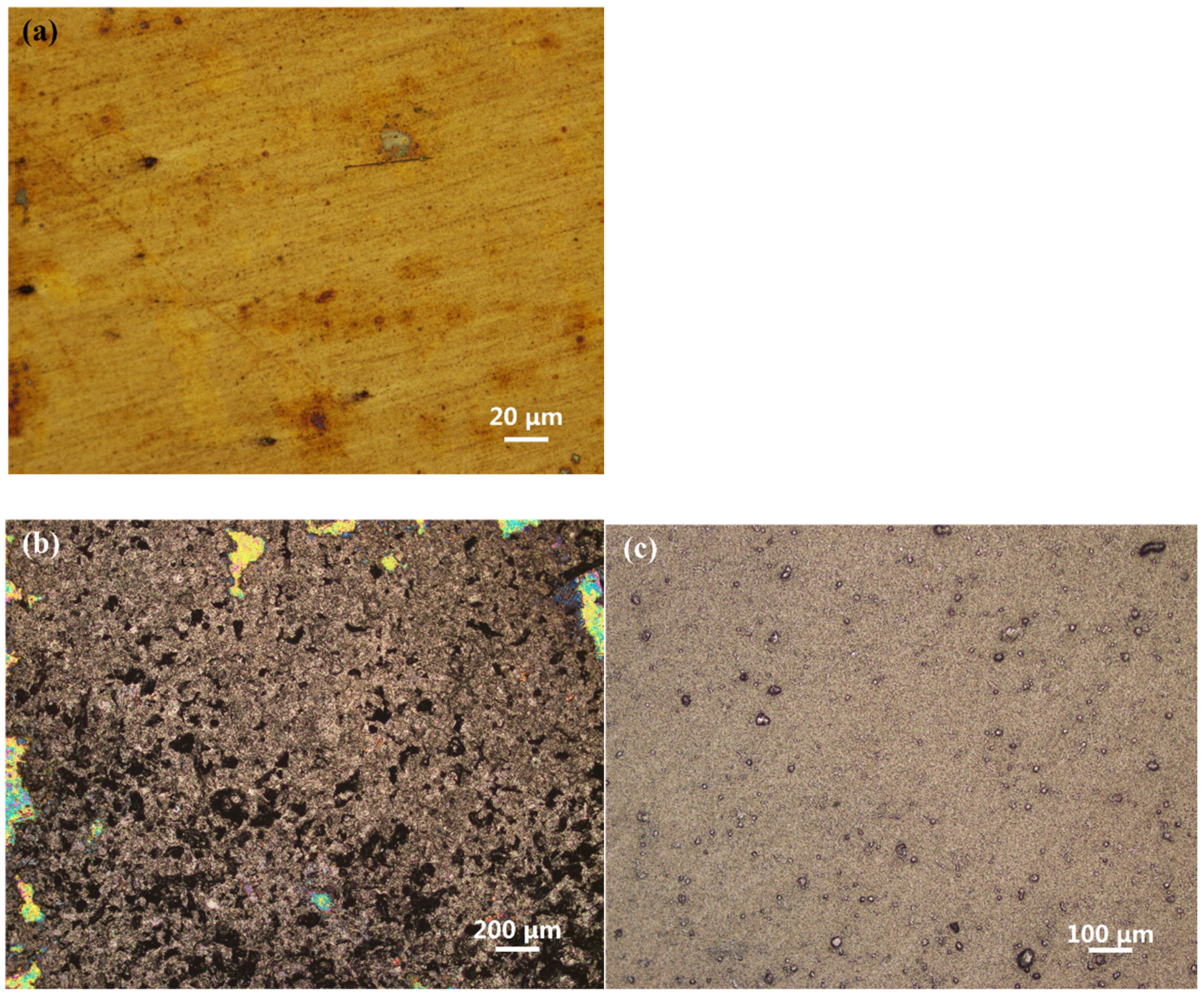
Figure 2 shows the surface characteristics of the three surfaces before tests. It is observed that the graphene coating surface prepared by the DCDM presents a thin layer of black graphene with a loose distribution, and the graphene thin layer is not uniform with some granular appearance on the surface, as shown in Figure 2b. This is a common phenomenon caused by the appearance of an uneven coating due to the ‘coffee ring’ effect, and a similar coating has also been reported many times in relevant tribological studies [18]. In contrast, the graphene coating surface treated by the CGCA exhibits a relatively uniform gray graphene thin layer, and the coating fits tightly to the metallic matrix without obvious pores, as shown in Figure 2c.
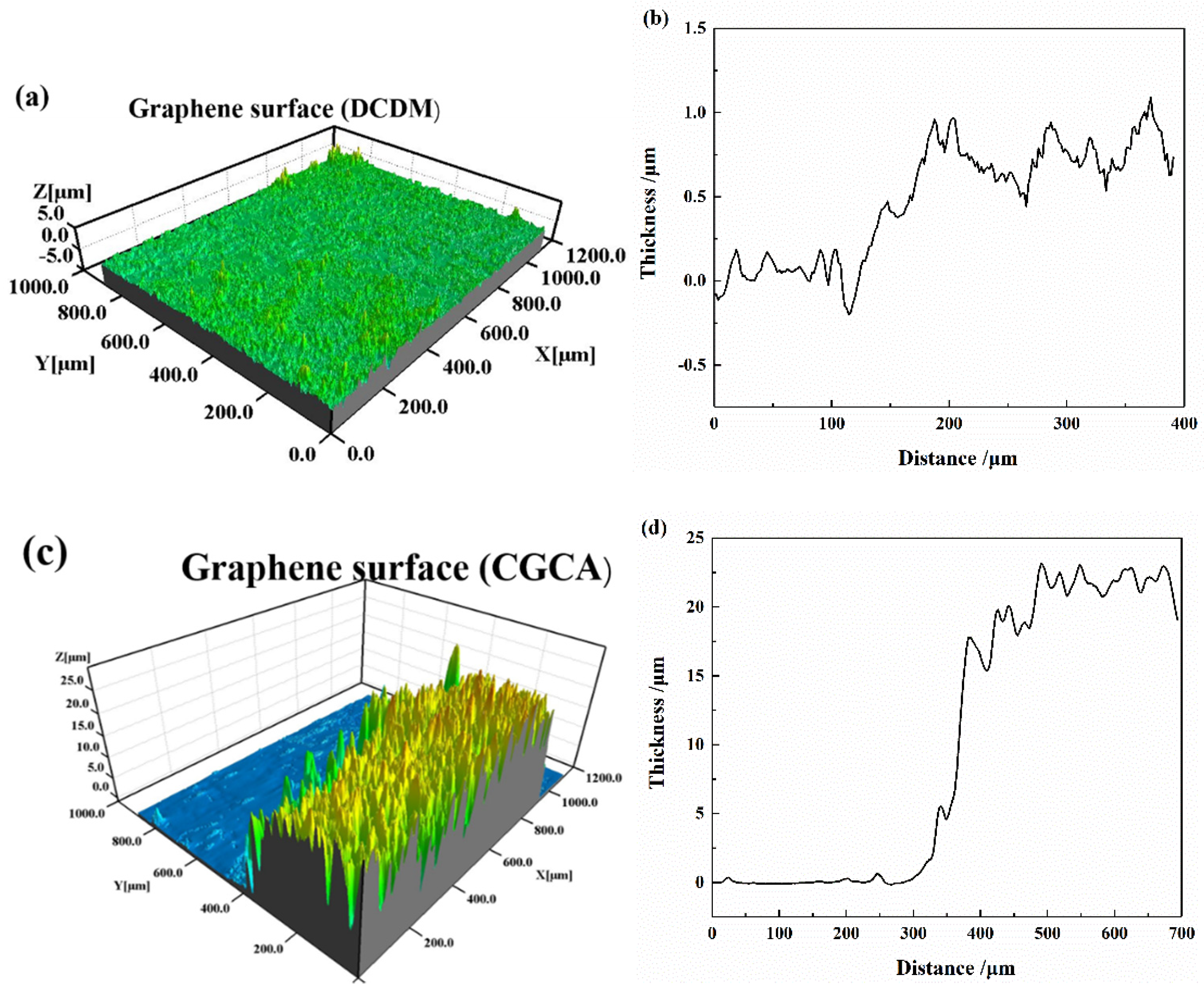
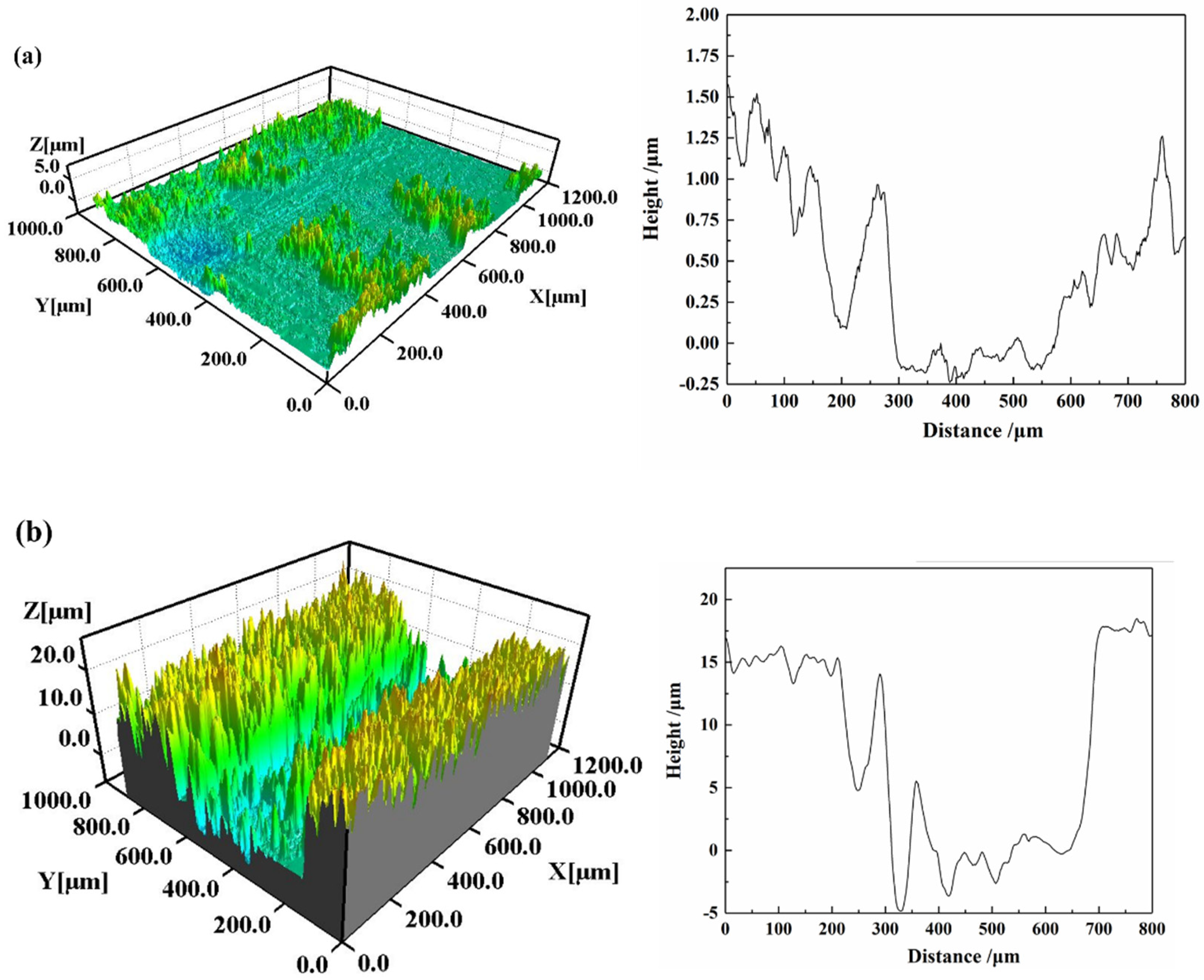
To further confirm the thickness of both graphene coatings, the samples of the two coatings are sliced in this study, and the thickness of the coatings is measured by using a white-light interferometer. The results are shown in Figure 3. It can be seen that the graphene coating obtained by the DCDM has a low thickness of about 1 micron. In contrast, the coating obtained by the CGCA method has a higher thickness of about 20 microns.

2.2. Test Setup

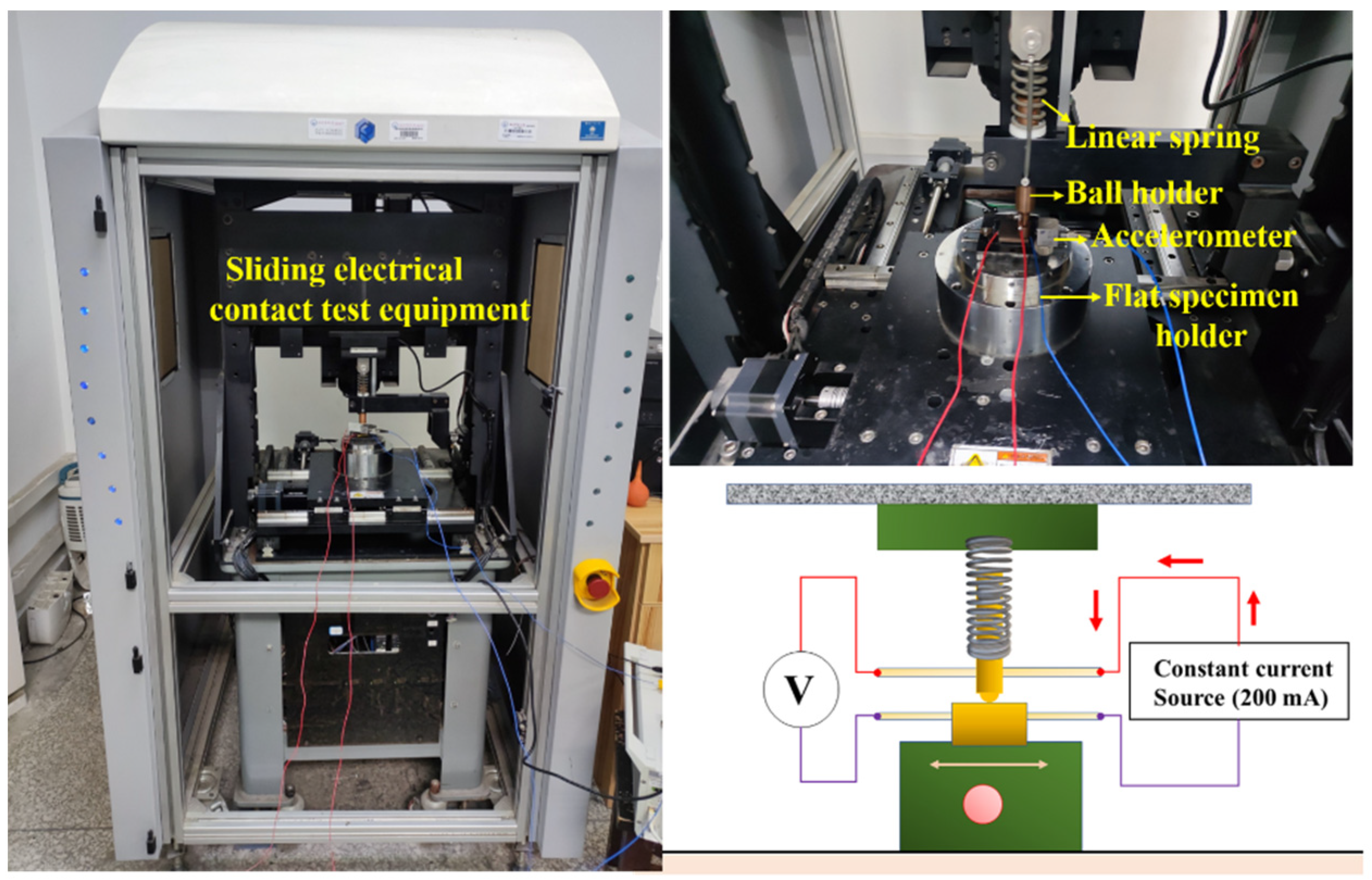
The sliding electrical contact tests are carried out on a self−designed tribological test device, which is mainly composed of an electrical contact system, a dynamic system, a friction pair system, and a fixture system. The device can realize the reciprocating sliding between the ball and the flat specimens. The test device is shown in Figure 4. The flat specimen is fixed on the lower table of the reciprocating sliding device, and the ball specimen is fixed on the bottom of the ball fixture. At the beginning of the test, the ball fixture drives the ball specimen to move down slowly, so that the ball specimen is in contact with the flat specimen under the constant normal load. Subsequently, the driving device drives the flat specimen to complete the reciprocating sliding. DC power equipment is used to apply constant electric current to the friction pair, and the ‘four-wire method’ is used to continuously measure the variation in contact voltage and resistance signal during the sliding process. A thermocouple is installed near the contact interface, which is used to measure the variation in interface temperature. The equipment realizes the synchronous acquisition and analysis of contact force, voltage signal, and temperature signal in the sliding process.
Before starting the test, the ball and flat specimens are degreased and cleaned using alcohol and distilled water in an ultrasonic cleaner, and the specimens are mounted on the setup after drying. The test conditions and parameters are as follows: the normal load is Fn = 2 N (=0.15 GPa), the reciprocating displacement amplitude is D = 3 mm, the reciprocating period is T= 3 s, the DC current is I = 200 mA, and the testing time is 600 s. The characteristics of friction, wear, and electrical contact signals during the friction process are collected for the following comparative analysis. The experimental environment is controlled in the dry under atmosphere (temperature of 24–27 °C, relative humidity of RH 60 ± 10%). Considering the randomness of tribological tests, each test is repeated at least three times to ensure the reliability of the results.

3. Test Results and Discussion

3.1. Analysis of Friction Coefficient

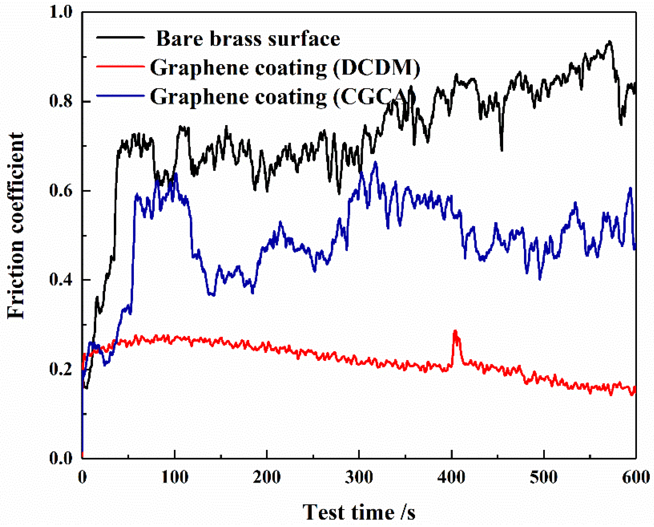
Figure 5 shows the variation in friction coefficient of the three surfaces during the tests. It can be seen that the friction coefficient of the bare brass surface is relatively low at the initial stage (less than 0.2). With the removal of surface pollutants and the natural oxide layer, the friction coefficient increases rapidly and reaches about 0.7 after 50 s. With the further progress in the test process, the friction coefficient fluctuates significantly due to the wear, adhesion, and ploughing occurring between the contact interface, and gradually exhibits a slight upward trend in the following sliding process, reaching about 0.9 at the end of the test. For the graphene coating surface prepared by the DCDM, the friction coefficient remains at a low level and exhibits a slight decreasing trend during the whole sliding process. At the end of the test, the friction coefficient remains at about 0.2, and no visible fluctuation can be observed from the curve of the friction coefficient signal. The reason for this phenomenon Is attributed to the remarkable self-lubricating effect of graphene, which reduces the interface adhesion effect during friction [16,20]. In contrast, for the graphene coating surface prepared by the CGCA, the friction coefficient reaches about 0.6 at the end of the test, and the signal fluctuates significantly during the sliding process. The reason for this phenomenon is presumed to be the wear and consumption of the conductive adhesive, which results in the weakening of its lubrication effect. In conclusion, the introduction of the graphene coating in the electric contact friction system can effectively reduce the friction coefficient; moreover, the graphene coating prepared by the DCDM shows the best potential in reducing the friction coefficient.

3.2. Contact Force Analysis

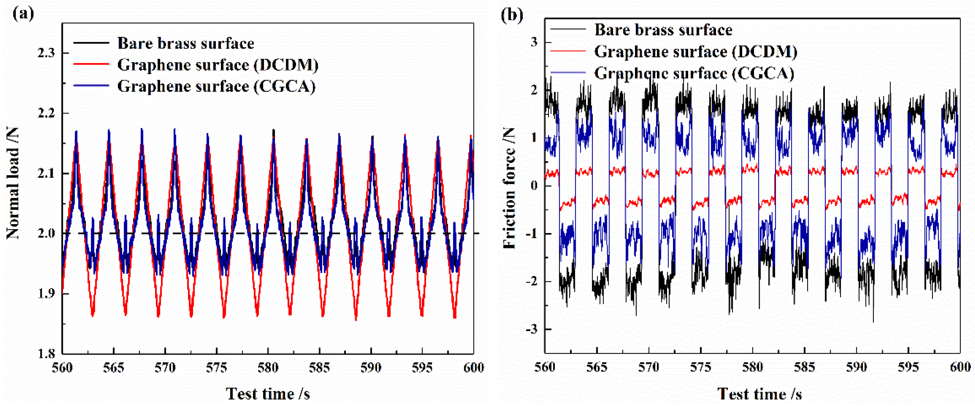
Figure 6 shows the contact force variation of the three surfaces during the test process. For the smooth brass surface and CGCA surface, no significant difference for the normal force signal at the interface can be observed during the steady stage, as shown in Figure 6a. In contrast, for the graphene coating surface prepared by the DCDM, the normal load signal generates a slight fluctuation due to the high elastic modulus of graphene, but still remains around 2 N.
Figure 6b shows the friction force signal of the three kinds of surfaces. It is observed that the direction of friction force varies with each cycle of reciprocating sliding. In addition, the friction force of the DCDM surface is found to be lowest, while the friction force of the bare brass surface is highest. The above characteristics are consistent with the results of the friction coefficient signal, which further proves that the graphene coating is able to reduce the interfacial friction, and the DCDM surface has the best potential in reducing the friction force.

3.3. Analysis of Contact Voltage

Figure 7 analyzes the contact voltages of the three surfaces under a constant current of 200 mA. It is found that for the bare brass surface, the contact voltage remains at 0.1 V during the whole friction process, suggesting that the contact surface maintains a good electrical contact situation. This phenomenon indicates that although the interface may be worn during the friction process, the ‘third bod’’ layer formed from the interface will not cause the disconnection of the contact interface. For the graphene surface prepared by the DCDM, the interface contact voltage increases significantly to 0.45 V in the initial stage, which is caused by the larger contact resistance of the graphene coating. With the consumption of the graphene coating, more and more metal substrates come into contact with each other; thus, the contact voltage gradually decreases and eventually becomes very close to that of the bare brass surface. In contrast, for the CGCA surface, the contact voltage at the interface also increases significantly in the initial stage, which is very similar to that of the DCDM surface. However, the voltage drops rapidly and approaches 0.1 V in a short period. It is speculated that the coating prepared by the CGCA is destroyed rapidly, resulting the direct contact between the brass (spherical specimen) and brass (flat specimen) interface. In conclusion, although the introduction of the graphene coating to the electrical contact system will lead to the increase in interface contact voltage in the initial stage, the contact voltage decreases rapidly after the coating is worn and gradually becomes stable. Therefore, the existence of the graphene coating will not have any negative effect on the stability of sliding electrical contact.

3.4. Wear Morphology Analysis

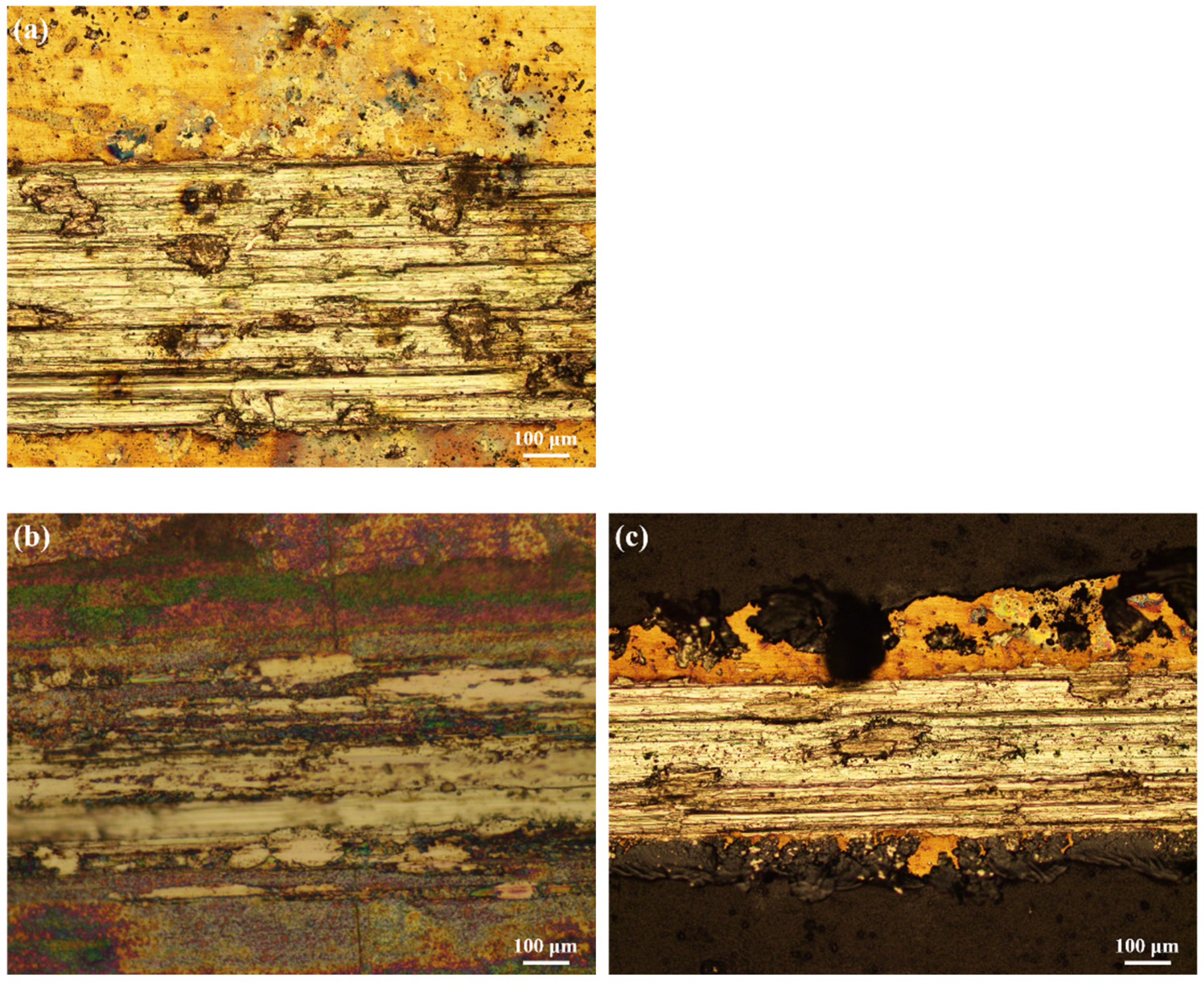
The wear morphologies of three different surfaces are analyzed by using optical microscope after tests, as illustrated in Figure 8. It is observed that the bare brass surface suffers serious wear, and visible furrows appear on the wear area. Moreover, material transfer and debris accumulation appear on the wear area as well. This phenomenon indicates that the wear mechanism of the bare brass surface is the combination of abrasive wear and adhesion wear in the sliding electrical contact. With the aggravation of wear and adhesion, the contact area gradually increases and accordingly enhances the adhesion force of the interface. Therefore, both the friction coefficient and tangential force increase significantly, as shown in Figure 5 and Figure 6. In contrast, for the surface prepared by the DCDM, the wear degree of the interface is significantly reduced, and no visible furrows can be seen from the wear track. Moreover, a large number of black graphene particles are scattered in the wear area, as shown in Figure 8b, realizing the effect of solid lubrication to a certain extent and reducing the wear of the interface, which consequently reduces the friction coefficient and friction force. Nevertheless, when the surface is prepared by the CGCA, the coating surface will be destroyed in a short period, which causes the coating material to be distributed on both sides of the wear track, and facilities the direct contact between the ball and flat specimens; thus, severe ploughs and material transfer caused by abrasive and adhesion are shown on the wear track, as can be seen in Figure 8c. In addition, it is observed that a large amount of debris is accumulated on the surface of the wear track, and the overall wear condition is similar to that of the bare brass surface. Therefore, for the CGCA surface, although the friction coefficient is reduced to a certain degree, it still fluctuates and rises significantly in the later stage of the test, as shown in Figure 5.
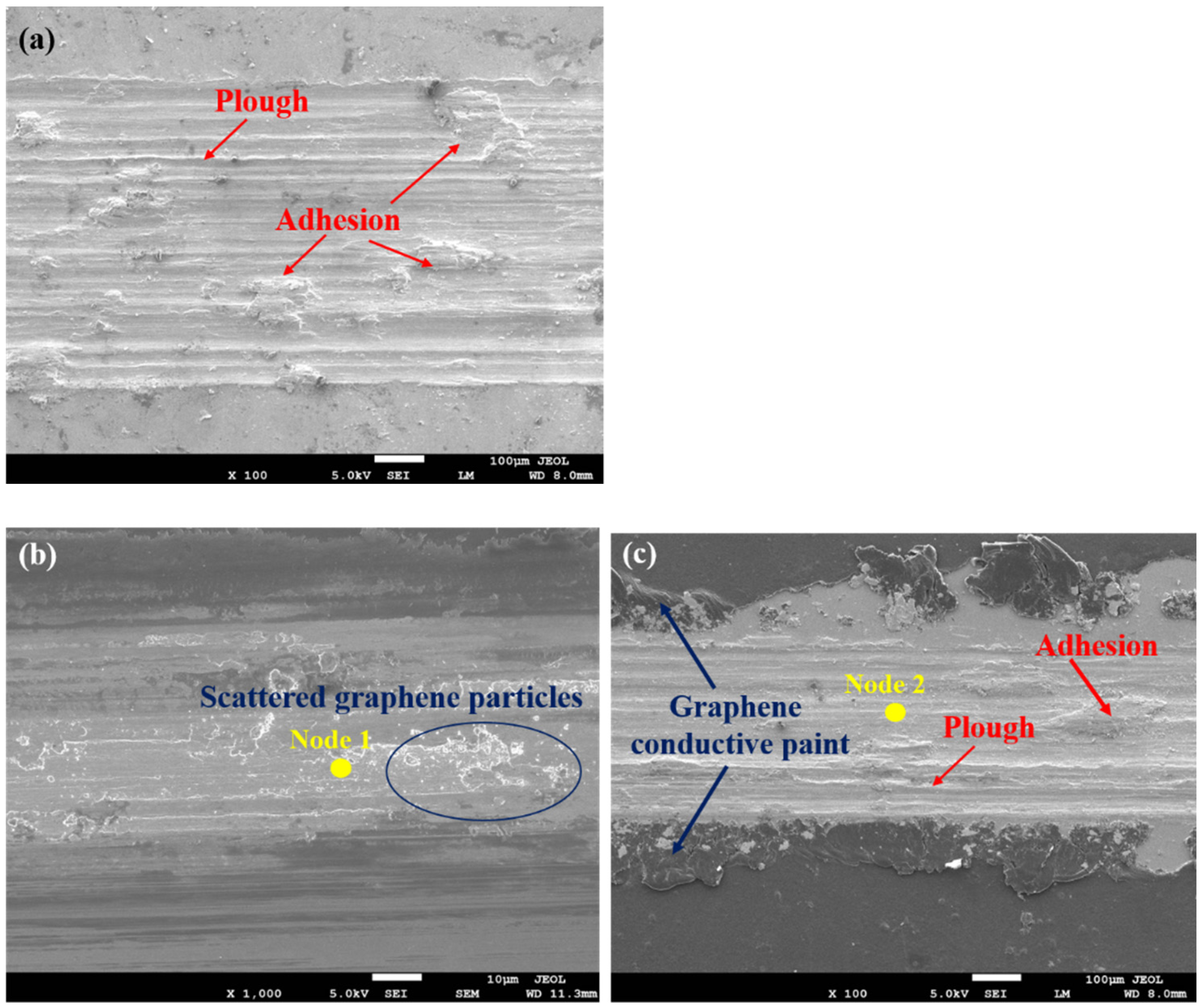
In order to further reveal the wear behaviors of different electrical contact interfaces, scanning electron microscopy (SEM) is used to observe the surface wear morphologies, and the results are shown in Figure 9. Deep scratches and furrows appear on the bare brass surface along the relative sliding direction, suggesting that there is obvious plowing behavior at the contact interface. In addition, wear plateaus formed by adhesion can be observed on the wear track as well, which further verifies that the wear mechanism of bare brass surface is the combination of abrasive wear and adhesive wear. While for the surface prepared by the DCDM, the wear degree of the interface is significantly reduced, no visible furrows formed by abrasive wear are shown on the wear track, and some graphene particles are scattered in the wear area, which further verifies the continuous lubrication effect of the graphene coating in the sliding electrical contact process. In contrast, the CGCA surface exhibits serious abrasive wear and adhesive wear, which is very similar to that of the bare brass surface. In addition, it can be seen that the graphene conductive paint is ‘squeezed’ and ‘repelled’ on both sides of the wear track; thus, the lubricating function of graphene is gradually lost as a consequence of the aggravated wear degree. The above analysis results are very consistent with the optical microscopy results shown in Figure 8.
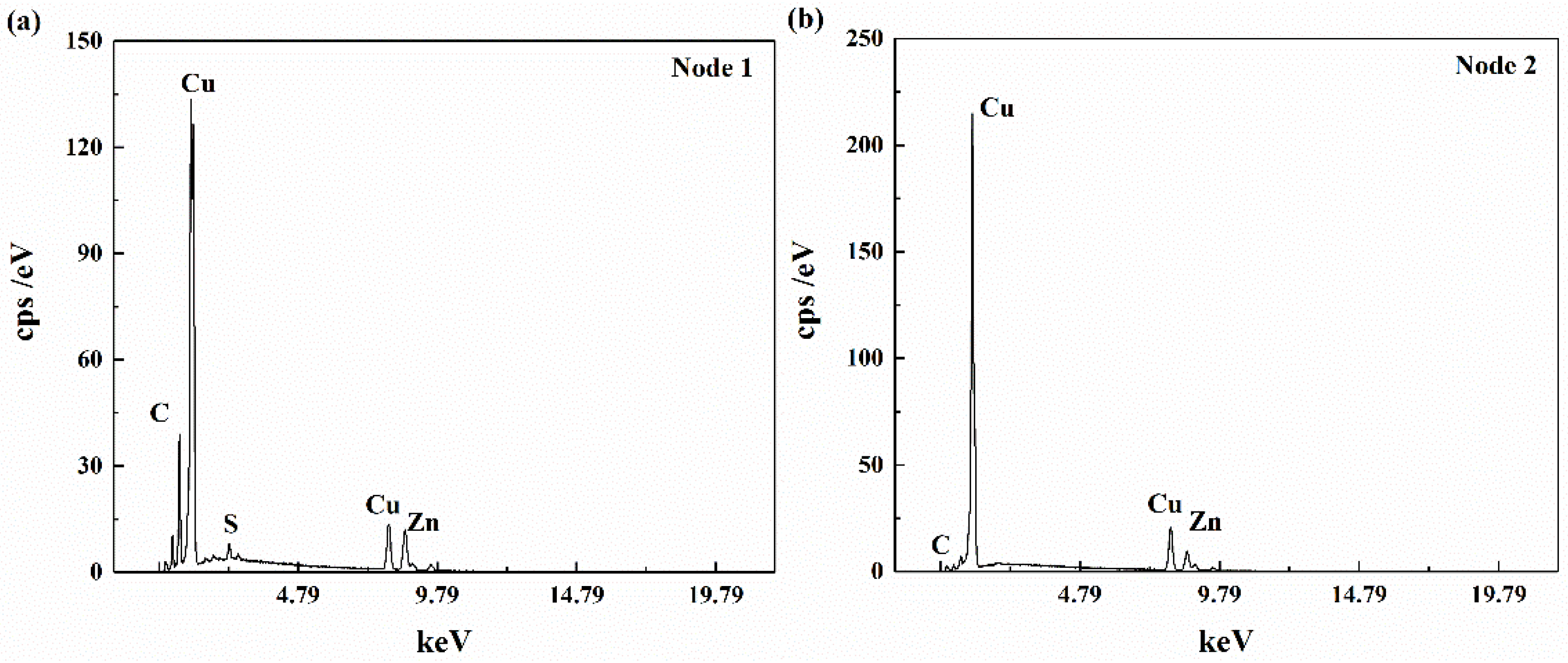
The elemental analysis is performed to detect the element distribution of the wear surface, as shown in Figure 10. For the wear scar of the graphene coating prepared by the DCDM, it is seen that there is a certain amount of C in the interface, which further indicates that the graphene coating remains in the wear area and provides continuous lubrication during the friction process. In contrast, for the graphene coating prepared by the CGCA method, it can be seen that the C content of the wear interface of the coating basically disappears, which indicates that the graphene coating is basically consumed and cannot provide continuous lubrication during the friction process. Notably, graphene prevents the metal surface from tribo-oxidation, thus ensuring the passivation concept [21,22].
The white-light interferometer is used to further test the wear morphologies of the two graphene coatings, and the results are shown in Figure 11. For the coating surface prepared by the DCDM, the wear is very slight, and no visible wear furrows can be observed in the wear track; only a certain amount of wear debris is accumulated at the end of the wear track. In contrast, the wear morphology of the coating surface obtained by the CGCA shows visible ploughing, and the graphene coating is stacked on both sides of the wear track and forms a certain ‘raised band’. The reason for this phenomenon is that the graphene coating prepared by the DCDM presents a loose granular shape, the wear particles fall off in the wear track, and they provide the lubrication effect, which causes the reduction in friction and wear, while for the coated surface prepared by the CGCA, the surface coating is relatively compacted and uniform, suggesting that the connection between the coating and substrate is relatively close. Therefore, the coating is damaged by wear during friction process, and the wear debris is composed of graphene particles and the wear material of metal subtract. As the debris is gradually repelled to the sides of the wear track, the lubrication effect of graphene greatly reduces and disappears.

4. Numerical Analysis and Discussion

4.1. Finite Element Model and Electric–Thermal–Mechanical Sequential Coupling Analysis

In this section, finite element analysis is performed to discuss the effect of the graphene coating in reducing friction and wear. It should be noted that the numerical simulation is only used to qualitatively explain the mechanism of the graphene coating in improving the friction and wear behavior of electrical contact, rather than to compare and analyze the tribological behavior of the two above-mentioned graphene coatings.
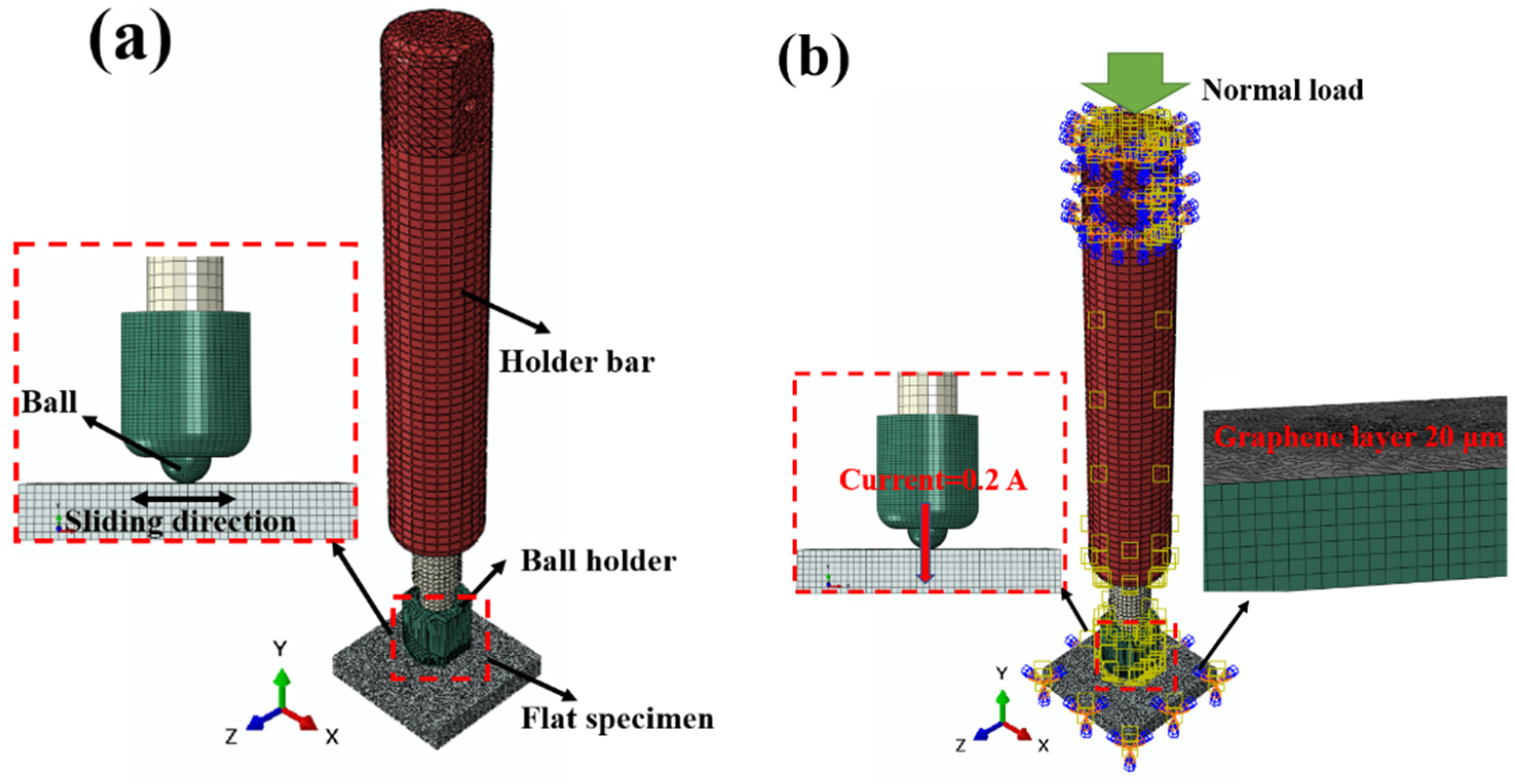
The simplified model of the friction system is established through measuring the dimensions of relevant components, as shown in Figure 12a. The model mainly consists of the fixture system, ball specimen, and flat specimen. The material parameters of brass (H65) are assigned to each component, as shown in Table 1. The model is meshed by C3D8 and C3D4 elements, and the contact mode is set as surface-to-surface (Standard). According to the mesh size of the contact pair, the top surface of the flat specimen is set as the master surface, and the bottom surface of the flat specimen is set as the slave surface. In order to reflect the interface characteristics of the surface coating, the graphene/graphite layer is set to 20 μm in thickness, and the corresponding material parameters are assigned, as shown in Table 1.
The boundary conditions of the model are defined according to the real test conditions, as shown in Figure 12b. The degrees of freedom (DOFs) of the top surface of the holder bar are constrained in both the X and Z directions, and a constant normal load (2 N) is applied to the top surface of the hold bar along the Y direction. The DOFs of the bottom surface of the flat specimen are constrained in both the Y and Z directions, and the velocity boundary condition is imposed along the X direction, so that the flat specimen can achieve reciprocating sliding in this direction. A constant current of 0.2 A is applied into the contact system to simulate the electrical contact condition. The ambient temperature is set to 25 °C.
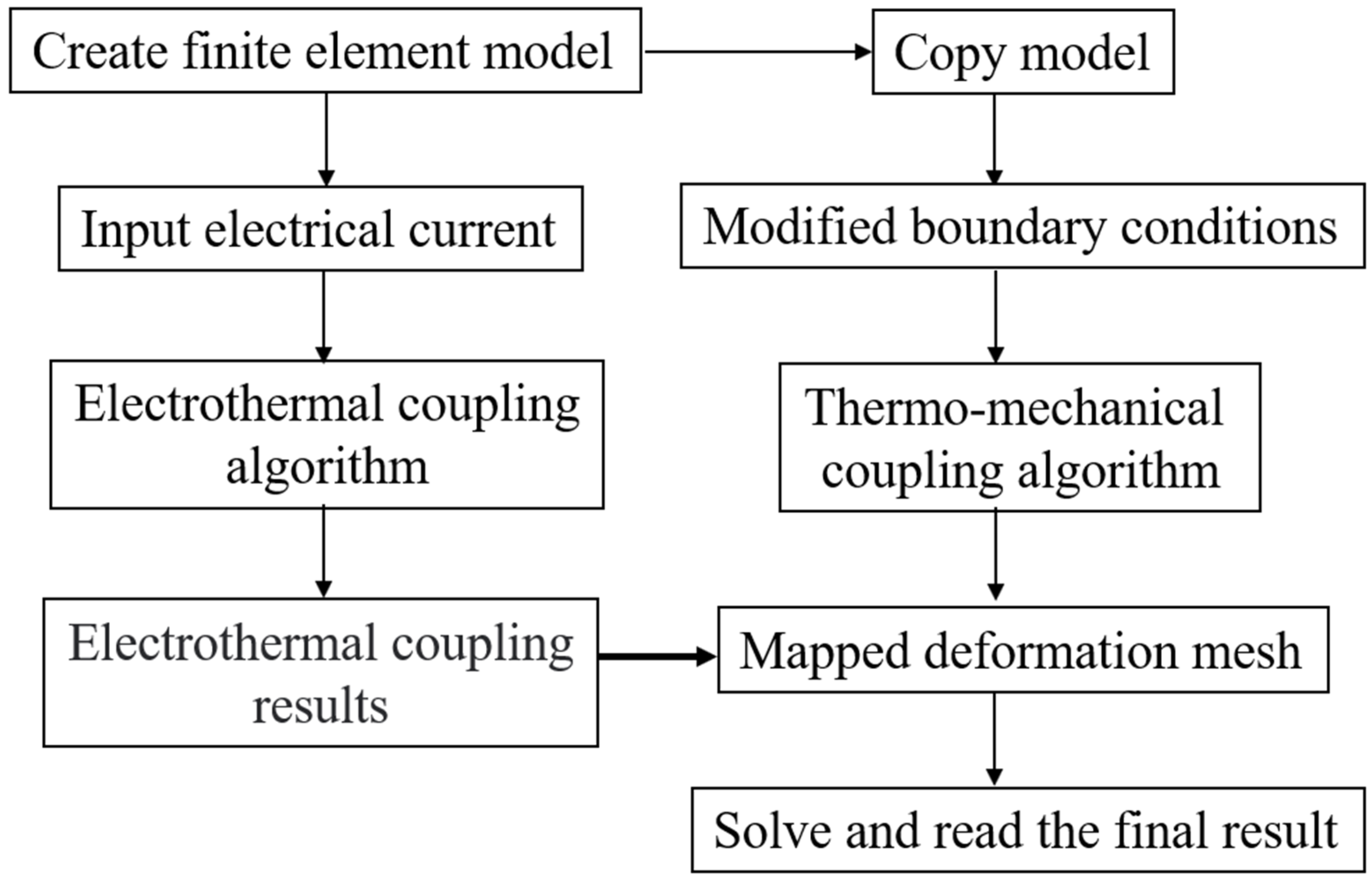
In this study, the electric–thermal–mechanical sequential coupling algorithm in ABAQUS is used to simulate the tribological behavior during sliding electrical contact, and the calculation process is shown in Figure 13. First, a constant current of 0.2 A is applied to the friction pair in static contact by the electro-thermal coupling algorithm, to simulate the temperature variation of the friction system and the thermal deformation of each element under the action of constant current. On this basis, the results file obtained by the electric-thermal coupling algorithm is set as the initial state of the friction system, which is used in the subsequent thermomechanical coupling calculation, and the tribological behaviors of the friction system are simulated during the sliding process. The friction model is the Coulomb friction model, and the contact formulation is the penalty contact method.

4.2. Electric–Thermal–Mechanical Coupling Analysis

4.2.1. Contact Displacement Analysis

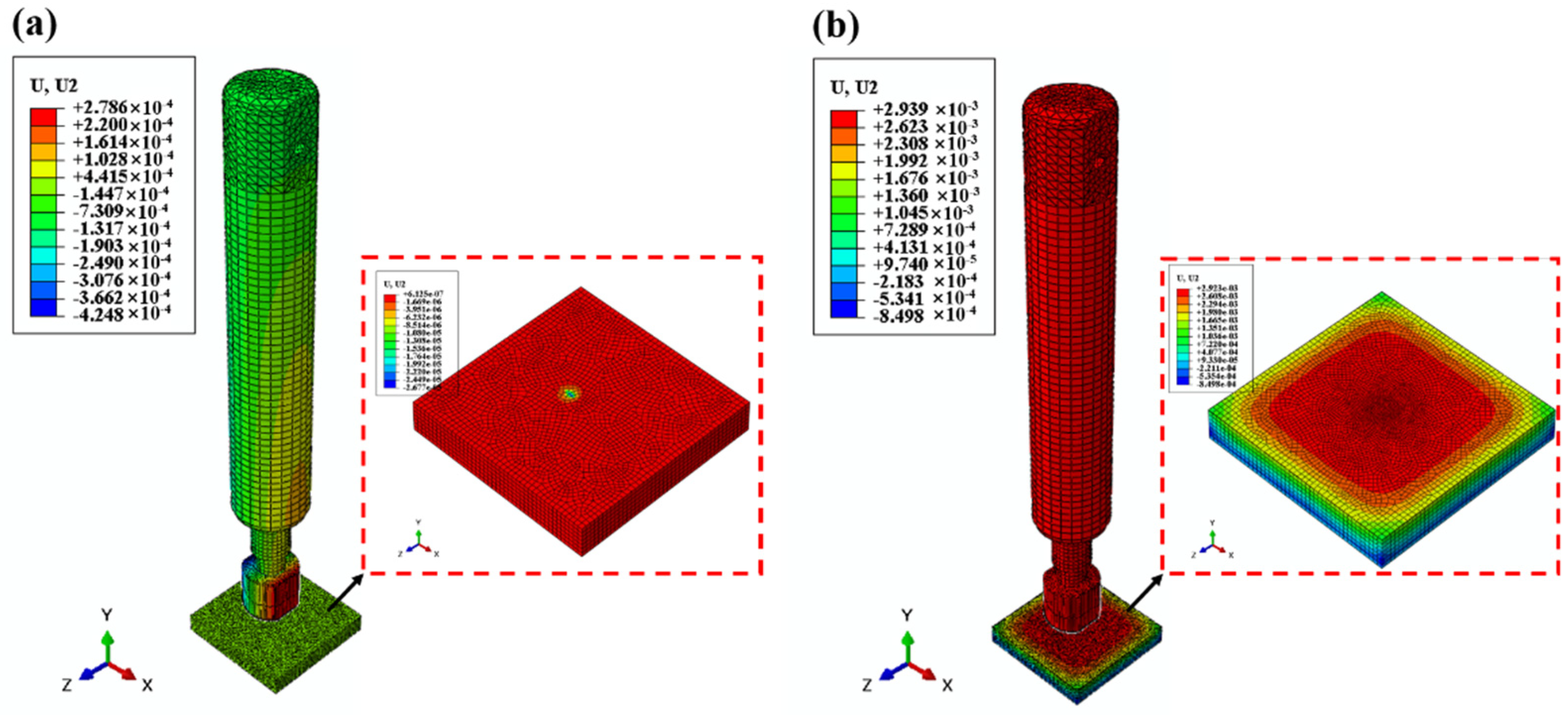
The contact displacements of the friction system in the condition of sliding electrical contact are extracted, as shown in Figure 14. It can be seen that for the bare brass surface, the displacement of the flat specimen decreases by about −2 × 10⁻⁵ mm due to the combined effect of electric current and load, resulting in the ‘embedding’ phenomenon between the ball specimen and the flat specimen. In the actual friction process, this phenomenon will evolve into material transfer between rubbing materials and generate possible abrasive wear and other phenomena. In contrast, when the surface of the flat specimen is coated with the 20 μm graphene layer, due to the good electrical conductivity, heat conduction characteristics, and large elastic modulus, the graphene layer exhibits a certain thermal expansion, and the height of expansion is about 3 × 10⁻³ mm. Therefore, the graphene layer is in good contact with the rubbing ball specimen, which avoids the direct contact between the substrates. As the coated surface is gradually worn away, the graphene particles fall back into the wear area and provide a continuous lubrication effect, as illustrated in Figure 15, which helps to reduce the friction coefficient and alleviate the wear degree of the interface, and consequently improves the stability of sliding electrical contact.

4.2.2. Contact Stress Analysis

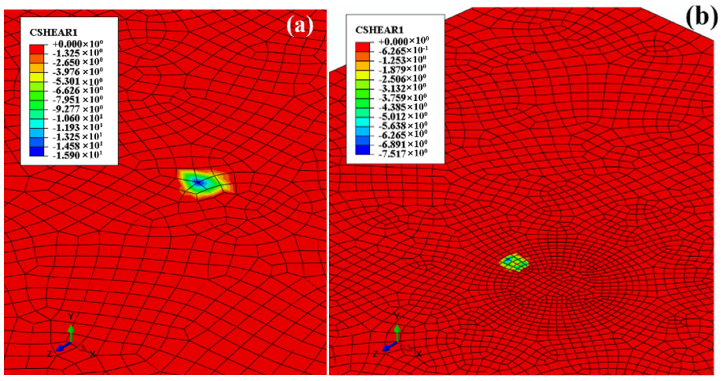
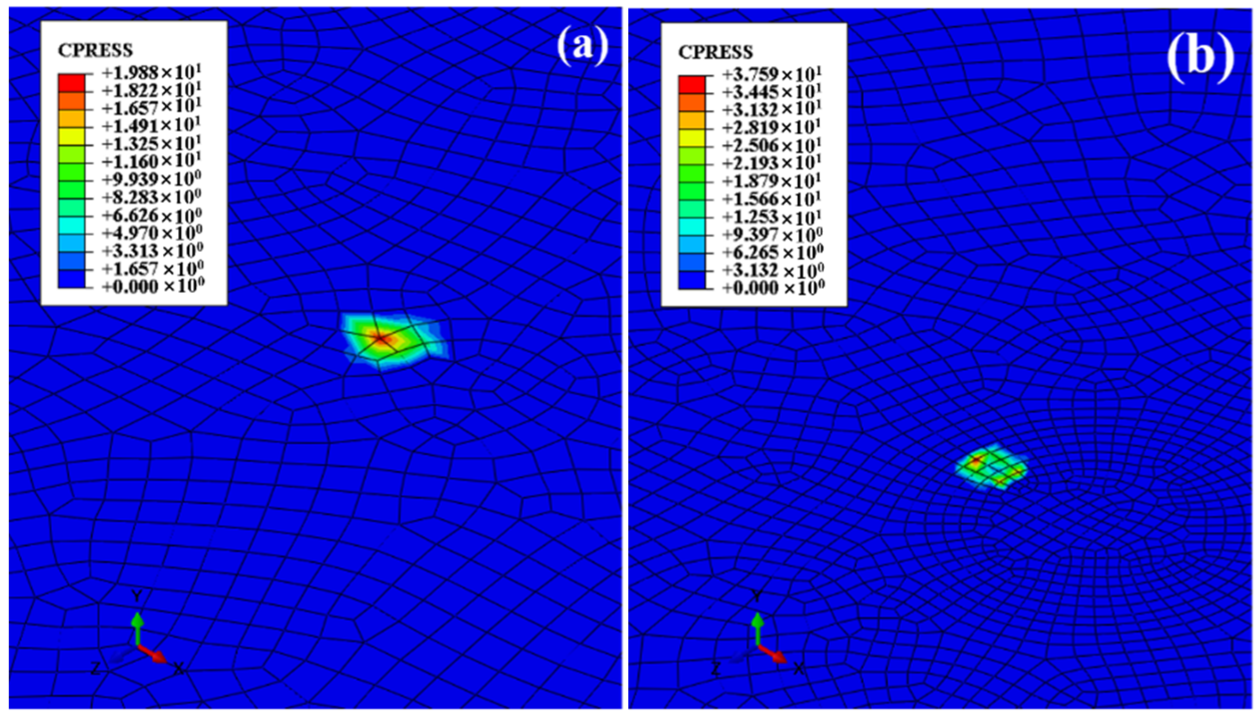
The shear stress of the friction system under sliding electrical contact is extracted, and the results are shown in Figure 16. It is found that the maximum shear stress on the bare brass surface is 15.9 MPa. In contrast, the shear stress of the surface with the graphene coating decreases visibly, and the maximum stress is only 7.517 MPa. The simulation results can validate the friction force analysis results shown in Figure 6, which verifies that the graphene-coated surface can significantly reduce the friction. Furthermore, the normal contact stresses of the friction systems are analyzed, as shown in Figure 17. It can be seen that the maximum normal stress of the bare brass surface is 19.88 MPa. Due to the large elastic modulus of the graphene layer and its expansion deformation in the normal direction, the normal contact stress of the surface with the graphene coating increases and the maximum stress is 37.59 MPa. The simulation results explain the fluctuation in the normal load shown in Figure 6, i.e., the fluctuation in normal load of the coating surface is larger than that of the bare brass surface. Combining the displacement analysis results shown in Figure 14, it is verified that the unique deformation of the coating causes the increase in the fluctuation of the normal force, while significantly reducing the friction force. In conclusion, the graphene coating has the effect of improving interface friction and wear by its unique deformation characteristics in the electrical contact state.

5. Conclusions

In this work, two kinds of graphene coatings are constructed on the brass surface by using two simple methods: the drop-coating drying method (DCDM) and coating graphene conductive adhesive (CGCA). A series of sliding electrical contact tests is carried out to detect the tribological performances of these two surfaces. Combined with the finite element analysis method, some conclusions are obtained as follows:
(1) The graphene coating can effectively reduce the friction coefficient and the friction force. In this work, the graphene coating prepared by the DCDM shows the best potential in reducing the friction coefficient and friction force.
(2) Although the presence of the graphene coating will lead to the increase in interface contact voltage at the initial stage, the voltage signal gradually becomes stable with the progress of friction and wear; thus, the graphene coating will not affect the stability of sliding electrical contact.
(3) For the DCDM surface, no visible furrows appear on the wear track, and the graphene particles can provide a solid lubrication effect and consequently reduce the interface wear. Meanwhile, for the CGCA surface, the graphene coating is worn and consumed in a short period of time; thus, the coating interface shows serious wear, and the overall wear performance is similar to that of the bare brass surface.
(4) Finite element analysis results show that the graphene coating has a certain thermal expansion when the electric current is applied, which avoids the direct contact between the metal substrates. Combined with the lubrication effect of graphene itself, the friction of the interface is reduced, and the wear degree of the interface is alleviated. However, the normal force fluctuation of the interface may increase. The results of numerical analysis reflect the experimental phenomenon well.

Author Contributions

D.W.: Data Curation, Formal Analysis, Software, Investigation, Writing—Original Draft; F.L.: Specimen Preparation, Writing—Original Draft; X.C.: Investigation, Software, Writing—Original Draft; H.L.: Investigation, Validation, Writing—Review and Editing; W.C.: Investigation, Validation, Writing—Review and Editing; P.Z.: Investigation, Methodology, Validation. All authors have read and agreed to the published version of the manuscript.

Funding

This research was supported by the National Natural Science Foundation of China (No. 52105220), the Natural Science Foundation of Sichuan Province (2022NSFSC1950), and the Project National United Engineering Laboratory for Advanced Bearing Tribology (No. 202102).

Institutional Review Board Statement

Not applicable.

Informed Consent Statement

Not applicable.

Data Availability Statement

Not applicable.

Conflicts of Interest

The authors declare no conflict of interest.

References

  1. Han, C.; Park, S.; Lee, H. Intermittent failure in electrical interconnection of avionics system. Reliab. Eng. Syst. Saf. 2018, 185, 61–71. [Google Scholar] [CrossRef]
  2. Kloch, K.T.; Kozak, P.; Mlyniec, A. A review and perspectives on predicting the performance and durability of electrical contacts in automotive applications. Eng. Fail. Anal. 2021, 121, 105143. [Google Scholar] [CrossRef]
  3. Cao, Z.F.; Xia, Y.Q.; Chen, C.; Zheng, K.; Zhang, Y. A synergetic strategy based on laser surface texturing and lubricating grease for improving the tribological and electrical properties of Ag coating under current-carrying friction. Friction 2021, 9, 978–989. [Google Scholar] [CrossRef]
  4. Kong, Z.; Swingler, J. Combined effects of fretting and pollutant particles on the contact resistance of the electrical con-nectors. Prog. Nat. Sci. Mater. Int. 2017, 27, 385–390. [Google Scholar] [CrossRef]
  5. Bouchoucha, A.; Chekroud, S.; Paulmier, D. Influence of the electrical sliding speed on friction and wear processes in an electrical contact copper–stainless steel. Appl. Surf. Sci. 2004, 223, 330–342. [Google Scholar] [CrossRef]
  6. Antler, M. Survey of Contact Fretting in Electrical Connectors. IEEE Trans. Compon. Hybrids Manuf. Technol. 1985, 8, 87–104. [Google Scholar] [CrossRef]
  7. Sun, Y.; Song, C.; Liu, Z.; Li, J.W.; Sun, Y.M.; Shangguan, B.; Zhang, Y.Z. Effect of relative humidity on the tribological/conductive properties of Cu/Cu rolling contact pairs. Wear 2019, 436, 203023. [Google Scholar] [CrossRef]
  8. Beake, B.D.; Harris, A.J.; Liskiewicz, T.W.; Wagner, J.; McMasterd, S.J.; Goodes, S.R.; Neville, A.; Zhang, L. Friction and electrical contact resistance in reciprocating nano-scale wear testing of metallic materials. Wear 2021, 474, 203866. [Google Scholar] [CrossRef]
  9. Cao, Z.; Xia, Y.; Liu, L.; Feng, X. Study on the conductive and tribological properties of copper sliding electrical contacts lubricated by ionic liquids. Tribol. Int. 2018, 130, 27–35. [Google Scholar] [CrossRef]
  10. Poljanec, D.; Kalin, M.; Kumar, L. Influence of contact parameters on the tribological behaviour of various graphite/graphite sliding electrical contacts. Wear 2018, 406, 75–83. [Google Scholar] [CrossRef]
  11. Zhao, H.; Feng, Y.; Zhou, Z.; Qian, G.; Zhang, J.C.; Huang, X.C.; Zhang, X.B. Effect of electrical current density, apparent contact pressure, and sliding velocity on the electrical sliding wear behavior of Cu-Ti3AlC2 composites. Wear 2020, 444, 203156. [Google Scholar] [CrossRef]
  12. Wang, Y.A.; Li, J.X.; Yan, Y.; Qiao, L.J. Effect of electrical current on tribological behavior of copper-impregnated metallized carbon against a Cu-Cr-Zr alloy. Tribol. Int. 2012, 50, 26–34. [Google Scholar] [CrossRef]
  13. Ghosh, S.; Calizo, I.; Teweldebrhan, D.; Pokatilov, E.P.; Nika, D.L.; Balandin, A.A.; Bao, W.; Miao, F.; Lau, C.N. Extremely high thermal conductivity of graphene: Prospects for thermal management applications in nanoelectronic circuits. Appl. Phys. Lett. 2008, 92, 151911. [Google Scholar] [CrossRef] [Green Version]
  14. Zhang, L.; Zhang, F.; Yang, X.; Long, G.K.; Wu, Y.P.; Zhang, T.F.; Leng, K.; Huang, Y.; Ma, Y.F.; Yu, A.; et al. Porous 3D graphene-based bulk materials with exceptional high surface area and excellent conductivity for super capacitors. Sci. Rep. 2013, 3, 1408. [Google Scholar] [CrossRef] [PubMed] [Green Version]
  15. Simon, P.; Gogotsi, Y. Capacitive Energy Storage in Nanostructured Carbon–Electrolyte Systems. Accounts Chem. Res. 2012, 46, 1094–1103. [Google Scholar] [CrossRef]
  16. Berman, D.; Erdemir, A.; Sumant, A.V. Graphene as a protective coating and superior lubricant for electrical contacts. Appl. Phys. Lett. 2014, 105, 231907. [Google Scholar] [CrossRef]
  17. Berman, D.; Erdemir, A.; Sumant, A.V. Reduced wear and friction enabled by graphene layers on sliding steel surfaces in dry nitrogen. Carbon 2013, 59, 167–175. [Google Scholar] [CrossRef]
  18. Mao, F.; Wiklund, U.; Andersson, A.M.; Jansson, U. Graphene as a lubricant on Ag for electrical contact applications. J. Mater. Sci. 2015, 50, 6518–6525. [Google Scholar] [CrossRef] [Green Version]
  19. Mao, J.; Chen, G.; Zhao, J.; He, Y.; Luo, J. An investigation on the tribological behaviors of steel/copper and steel/steel friction pairs via lubrication with a graphene additive. Friction 2020, 9, 228–238. [Google Scholar] [CrossRef] [Green Version]
  20. Sahoo, S.K.; Mallik, A. Fundamentals of fascinating graphene nanosheets: A comprehensive study. Nano 2019, 14, 1930003. [Google Scholar] [CrossRef]
  21. Restuccia, P.; Righi, M.C. Tribochemistry of graphene on iron and its possible role in lubrication of steel. Carbon 2016, 106, 118–124. [Google Scholar] [CrossRef] [Green Version]
  22. Saini, V.; Seth, S.; Ramakumar, S.S.V.; Bijwe, J. Carbon Nanoparticles of Varying Shapes as Additives in Mineral Oil Assessment of Comparative Performance Potential. ACS Appl. Mater. Interfaces 2021, 13, 38844–38856. [Google Scholar] [CrossRef] [PubMed]
  23. Georgantzinos, S.K.; Giannopoulos, G.I.; Anifantis, N.K. Numerical investigation of elastic mechanical properties of gra-phene structures. Mater. Des. 2010, 31, 4646–4654. [Google Scholar] [CrossRef]
  24. Chandra, Y.; Adhikari, S.; Flores, E.S.; Figiel, L. Advances in finite element modelling of graphene and associated nanostructures. Mater. Sci. Eng. R: Rep. 2020, 140, 100544. [Google Scholar] [CrossRef]
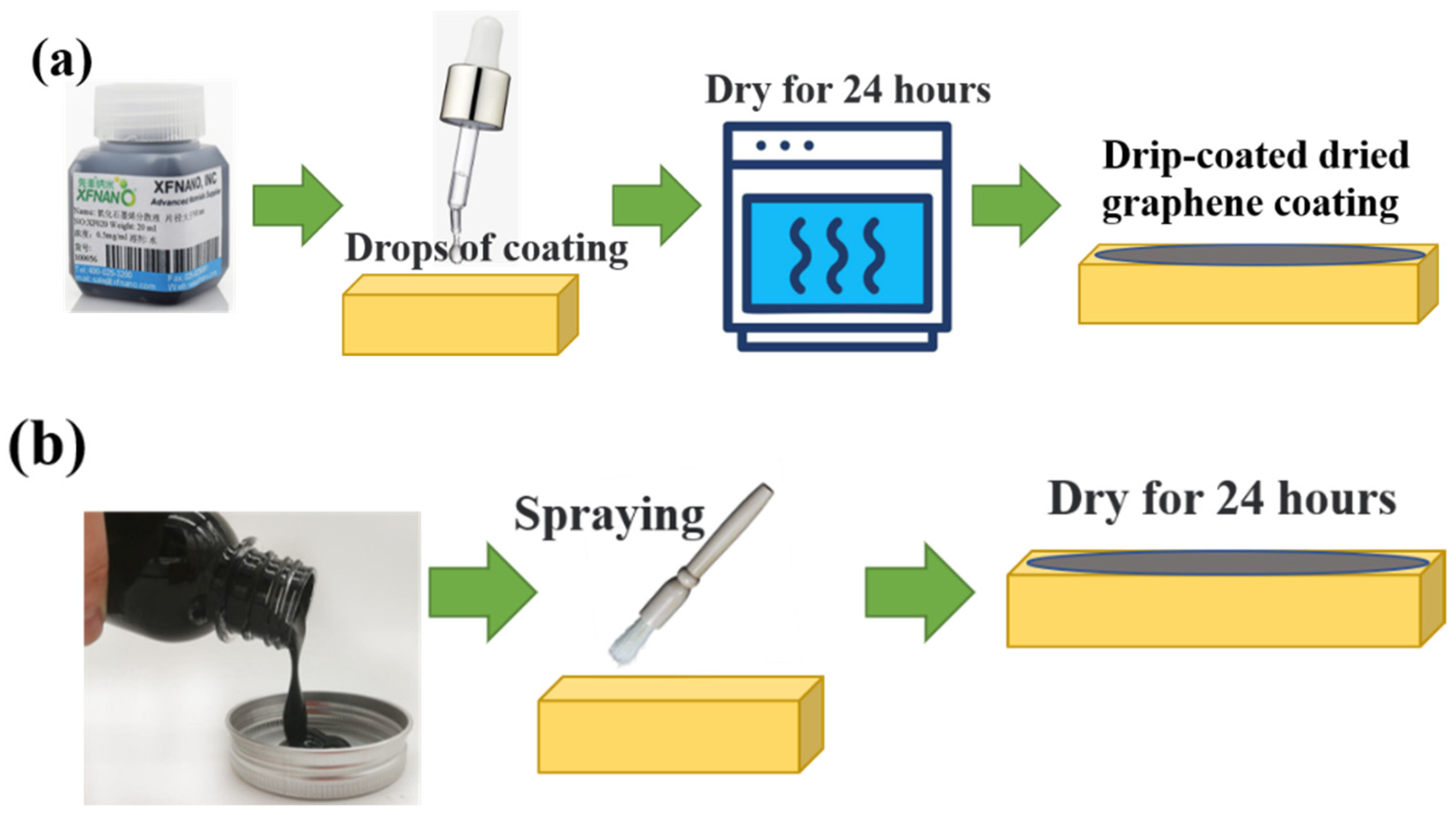
Figure 1. Preparation process of graphene coating by DCDM (a) and CGCA (b).
Lubricants 10 00305 g001
Figure 2. Optical images of bare brass surface (a), graphene coating surface prepared by DCDM, (b) and graphene coating surface prepared by CGCA (c) before tests.
Lubricants 10 00305 g002
Figure 3. White-light image and two−dimensional profile of graphene coating surface prepared by DCDM (a,b) and graphene coating surface prepared by CGCA (c,d).
Lubricants 10 00305 g003
Figure 4. The schematic diagram of the test setup.
Lubricants 10 00305 g004
Figure 5. The friction coefficient of the three different surfaces.
Lubricants 10 00305 g005
Figure 6. The normal load (a) and friction force (b) of the three different surfaces in the steady stage.
Lubricants 10 00305 g006
Figure 7. The voltage signals of the three different surfaces.
Lubricants 10 00305 g007
Figure 8. The optical images of the bare brass surface (a), graphene coating surface prepared by DCDM (b), and graphene coating surface prepared by CGCA (c) after tests.
Lubricants 10 00305 g008
Figure 9. SEM images of the bare brass surface (a), graphene coating surface prepared by DCDM (b), and graphene coating surface prepared by CGCA (c) after tests.
Lubricants 10 00305 g009
Figure 10. Element distribution in the wear scar of the DCDM graphene coating (a) and CGCA graphene coating (b).
Lubricants 10 00305 g010
Figure 11. White-light interferogram of graphene coating surface prepared by DCDM (a) and CGCA (b) after tests.
Lubricants 10 00305 g011
Figure 12. Finite element model of the test setup (a) and the corresponding boundary condition (b).
Lubricants 10 00305 g012
Figure 13. Flowchart of electric–thermal–mechanical sequential coupling calculation.
Lubricants 10 00305 g013
Figure 14. Normal displacement of bare brass surface (a) and graphene coating surface (b).
Lubricants 10 00305 g014
Figure 15. Graphene layer behavior at different states.
Lubricants 10 00305 g015
Figure 16. Shear force of bare brass surface (a) and graphene coating surface (b).
Lubricants 10 00305 g016
Figure 17. Contact pressure of bare brass surface (a) and graphene coating surface (b).
Lubricants 10 00305 g017
Table 1. Material parameters of brass and graphene in finite element model [23,24].
Parameters
Material NameBrassGraphene layer
Elasticity modulus /MPa112,0001,100,000
Poisson’s ratio0.30.4
Thermal conductivity W/(mm°C)0.165.3
Thermal expansivity /°C−11.776 × 10−51 × 10−6
Electrical conduction23,200100,000
Publisher’s Note: MDPI stays neutral with regard to jurisdictional claims in published maps and institutional affiliations.