


Abstract
To reduce wheel loading caused by chip adhesion in the grinding of titanium alloys, a new method named ultrasonic-assisted plasma oxidation modification grinding is suggested. The processing principle was introduced in this research, and based on that, the experimental apparatus was established. Then, the surface and cross-sectional morphologies of a workpiece with an oxide layer were characterized, followed by the detection of its microhardness and surface composition. On this basis, in the absence and presence of the oxide layer, the dynamic changes in wheel loading on the grinding wheel surface and the evolution behavior of chip adhesion on the grains were both investigated after gradually increasing the grinding passes. Finally, the effects of wheel loading on the ground surface morphologies were analyzed. The results showed that the oxide layer with low microhardness was mainly composed of TiO2 and Al2O3. Moreover, with an increase in grinding passes, the overall occupied area of chip adhesion on the grinding wheel surface increased proportionally in the absence of the oxide layer, which finally caused severe wheel loading. Conversely, yet at almost the same rate, the overall occupied area of chip adhesion increased after remaining comparatively unchanged in a short range of grinding passes in the presence of the oxide layer, which effectively inhibited the wheel loading. Compared with the ground surface obtained without an oxide layer, the generation of plastic-stacking was significantly restrained with the assistance of the oxide layer, thereby improving the ground surface quality.
1. Introduction
In the fields of marine industry, aerospace, high-speed rail transit, and medical equipment, titanium alloys have been increasingly applied because of their high specific strength, outstanding thermal stability, strong corrosion resistance, and excellent fatigue resistance [1,2]. As a typical finishing process, grinding is usually applied to manufacture titanium alloy components with high surface integrity and dimensional accuracy for high-precision equipment [3]. However, the low thermal conductivity of titanium alloys (7 W/mK, which is only about 16.7% of that of steel) can prevent approximately 80% of the heat produced in the grinding zone from transferring to the surrounding environment through a workpiece in time [1]. In such a high-temperature environment, through mechanical interlocking and the chemical affinity between the chips and grain/bonding materials, titanium alloy chips could weld onto the grains’ cutting edges and accumulate in the space between grains, resulting in wheel loading [4]. Hence, the cutting ability of a grinding wheel is decreased, which could raise the grinding force and deteriorate the ground surface [5].
In the grinding of titanium alloys, the key to constraining wheel loading is to reduce the heat produced in the grinding zone and to transfer the heat from the grinding zone to the surrounding environment in time. On the one hand, the grinding parameters have been studied to promote a reduction in the heat produced in the grinding zone. Pashmforoush et al. [6] found that a reduction in the depth of the cut and feed rate (i.e., the material removal rate) can inhibit wheel loading in dry grinding. On the other hand, considering timely heat dissipation from the grinding zone to the surrounding environment, cryogenic cooling lubrication using liquid nitrogen (LN2) and a grinding wheel with an internal cooling lubricant supply (GIC) were introduced into the grinding of titanium alloys. Regarding LN2 cryogenic cooling lubrication, Gupta et al. [7] compared tool wear in the machining process of α-β titanium alloys under a dry and LN2 cooling environment. It was found that the decrease in flank wear was up to 62.3% when the LN2 cooling system was included in the machining process. Elanchezhian et al. [8] found that using LN2 could reduce the normal grinding force, tangential grinding force, and grinding zone temperature by 12%, 27%, and 55%, respectively, compared with traditional cooling lubrication. In this case, the wheel loading was considerably inhibited, reducing the surface roughness Ra by 38%. Moreover, in the field of GIC, Jan et al. [9] designed and manufactured a GIC whose hydraulic structure was like that of a centrifugal pump impeller, which can uniformly supply coolant to the grinding zone at a grinding speed of 60 m/s. Li [10] developed a cup-shaped GIC and utilized it in grinding, reducing the grinding zone temperature by 50% and inhibiting wheel loading markedly.
In terms of reducing the heat produced in the grinding zone, the contradiction between a reduction in the grinding amount and an improvement in the processing efficiency in titanium alloy grinding is inevitable. On the other hand, involved in promoting heat dissipation, LN2 cryogenic cooling lubrication and GIC have achieved specific effects in inhibiting wheel loading, but there are still some limitations. For example, using LN2 requires a complex cooling circulation system, making applying this technology in the grinding field challenging. In addition, the manufacturing of a GIC is complex, and the coolant flow inside a GIC causes grinding wheel forced vibration, which can reduce the ground surface quality. Therefore, it is necessary to propose a new processing technology to constrain wheel loading and improve the ground surface quality.
Considering that titanium alloys’ low thermal conductivity and high chemical reactivity are the key impactors on wheel loading, an effective measure is to explore a new processing technology that can modify the titanium alloy’s material before grinding. Plasma oxidation is one of the typical methods for the surface modification of titanium alloys. Plasma arc discharge acts on the work material to generate a series of reactions (such as thermochemistry, electrochemistry, and plasma chemistry), producing an oxide layer on the workpiece surface [11,12]. In the study of plasma arc welding, Li et al. [13] pointed out that ultrasonic vibration added to a tungsten electrode during welding can improve the pressure and current density of the plasma arc, enhancing its penetration ability. Based on these, ultrasonic-assisted plasma oxidation modification grinding was suggested.
In this research, the processing principle is described first. Then, according to the processing principle, the plasma oxide layer is prepared, followed by the detection of its microhardness and surface composition. On this basis, the dynamic changes in macroscopic wheel loading on the grinding wheel surface and the adhesion evolution behavior between chips and abrasive grains are both analyzed after grinding workpieces without an oxide layer. Finally, in the absence and presence of the oxide layer, the formation mechanism of various ground surface morphologies after different grinding passes, combined with wheel loading on the grinding wheel surface, is explained.
2. Processing Principle and Experimental Details
2.1. Processing Principle
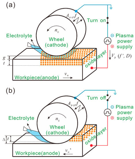
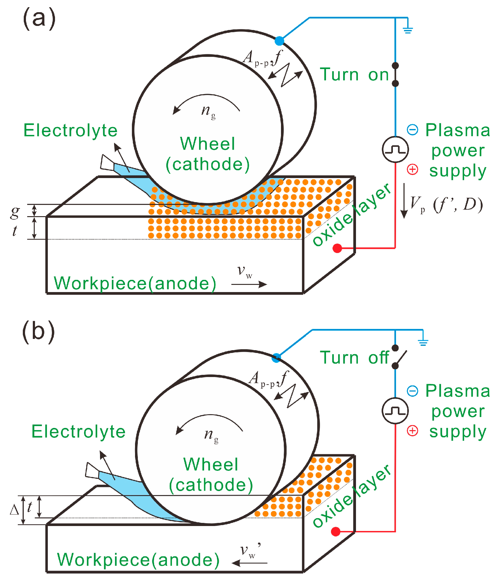
Figure 1 shows a schematic of the processing principle of ultrasonic-assisted plasma oxidation modification grinding. This processing is divided into two steps: forming an oxide layer on the titanium alloy workpiece surface through ultrasonic-assisted plasma oxidation (Figure 1a) and removing the oxide layer through grinding (Figure 1b).
Figure 1.
Schematic of the processing principle: (a) plasma oxidation process and (b) grinding process.
As shown in Figure 1a, an electrolyte is supplied to a given clearance with g at a definite flow rate during the oxidation process. Simultaneously, a pulsed electric voltage with frequency f’ and duty ratio D is provided between the workpiece as an anode and the conductive grinding wheel as a cathode to form plasma discharge between the electrodes. Electrochemistry, thermochemistry, and plasma chemistry reactions produce an oxide layer on the workpiece surface. Moreover, an ultrasonic vibration with frequency f and amplitude Ap-p is added to the grinding wheel to enhance the plasma intensity. Under the above conditions, the grinding wheel rotates anticlockwise with a rotation speed of ng and the workpiece moves right with a feed rate of vw to produce an oxide layer in a specific area of the workpiece surface. Followed by the grinding process, as shown in Figure 1b, both the plasma and ultrasonic power supplies are turned down. The grinding wheel rotating anticlockwise at a speed of ng and the workpiece moving left at a feed rate of vw’ perform the up-grinding under a given depth of cut Δ to remove the oxide layer.
Using the grinding wheel as a tool electrode would benefit the above processing. For example, the precision feed motion mechanism of the computer numerical control (CNC) machine center can be used to set the clearance g at the micron level to obtain a high-enough current density on the workpiece surface, quickly generating the oxide layer. Moreover, it does not need to be equipped with additional tool electrodes, thereby simplifying the experimental apparatus.
2.2. Experimental Details
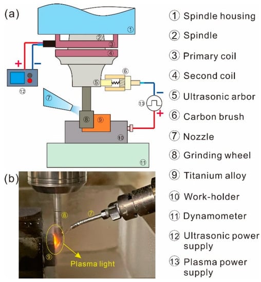
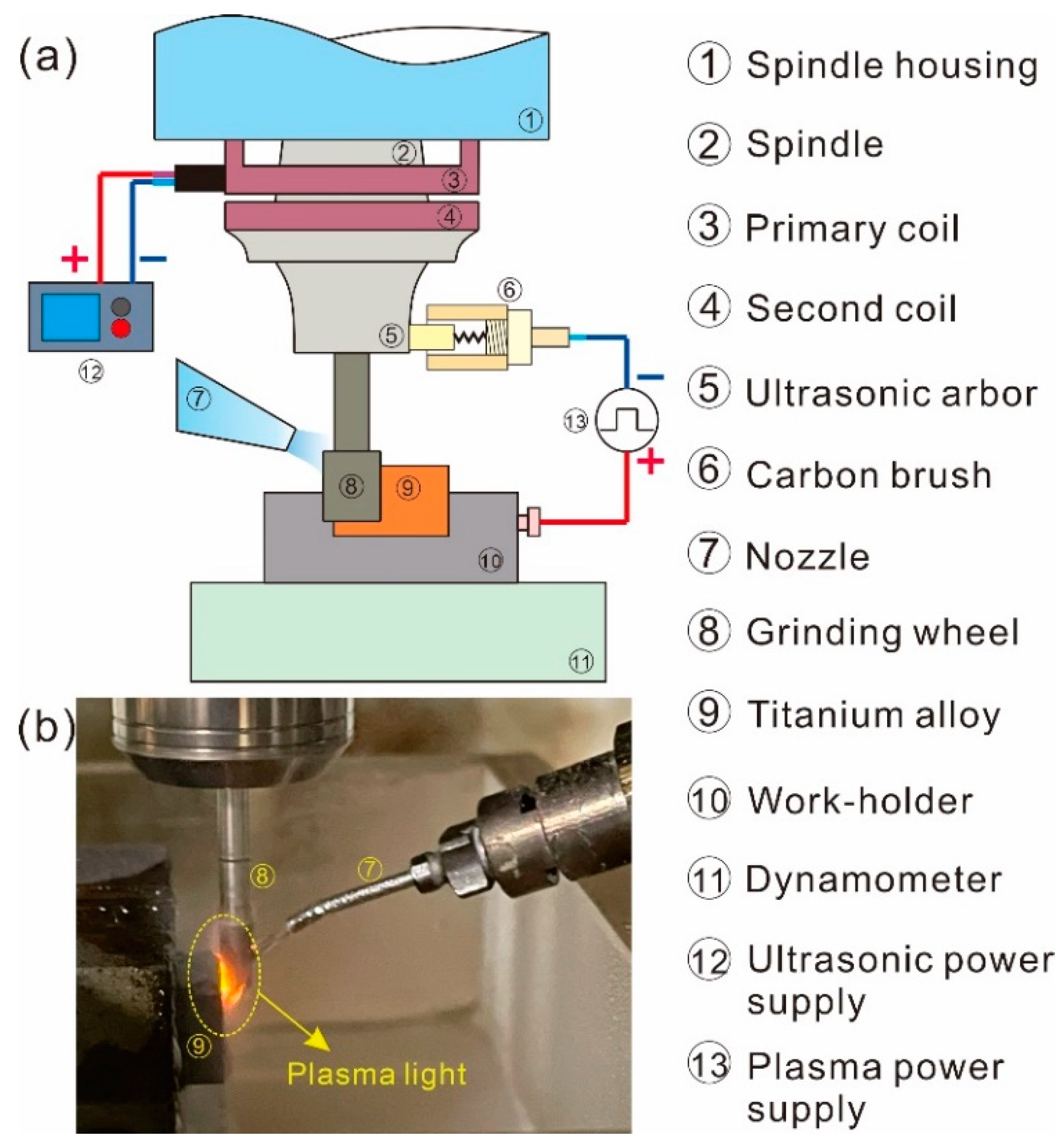
The apparatus was established based on a multi-axis CNC machine center, which can combine the advantages of grinding tools with milling feed rates. In this way, it can bring great flexibility in machining aeronautic components [14]. The apparatus was established based on a CNC machine center. As shown in Figure 2a, an ultrasonic arbor (UB40-C5-BT40, Takesho, Fukuoka, Japan) was clamped at the end of a spindle of a 3-axis CNC machining center (GX1000 PLUS, Hardinge, Elmera, NY, USA). A primary coil mounted on the spindle housing and a second coil inlaid in the ultrasonic arbor made up a wireless power transmission mechanism. Through this wireless power transmission mechanism, the ultrasonic power supply’s ultrasonic voltage can make the grinding wheel installed at the end of the ultrasonic arbor vibrate axially. It was noted that the booster structure of the ultrasonic arbor was designed to be a bar with a variable section [15,16], which can better increase the vibration amplitude generated in the transducer and ensure the transmission of that vibration to the tooltip. Moreover, this booster was used in the ultrasonic-assisted turning of the mild steels and increased the improvement of the surface roughness [16]. In addition, the phase-locked loop control strategy and constant current supply were applied to the ultrasonic vibration’s closed-loop system to keep the resonance of the tools with the stable vibration amplitude. The plasma power supply provides electric energy by connecting the grinding wheel and workpiece with the specifically designed carbon brush and workpiece holder. As shown in Figure 2b, the plasma light between the grinding wheel and workpiece was excited under the condition of the appropriate process parameters. This research selected Ti-6Al-4V, a commonly used titanium alloy, as the work material.
Figure 2.
Schematic of the experimental apparatus (a) and a picture of the plasma light produced between the grinding wheel and workpiece (b).
Before an operation of the tests for obtaining the properties of the oxide layer, the optimal process parameters were extracted from parameter combination tests to produce a plasma oxidation layer. As the voltage increased from 180 V to 210 V under the condition of the other constant parameters, the thickness of the plasma oxidation layer increased, which was caused by the increase in the current density. Then, when the voltage was further increased from 210 V to 270 V, the thickness of the oxide layer decreased because the electric energy was consumed by the produced spark, which can also deteriorate the wheel and workpiece surfaces. As the duty ratio of the voltage increased from 20% to 65% or the electrolyte concentration increased from 0.8 mol/L to 1.4 mol/L, the variation of the thickness of the plasma oxidation layer showed a similar trend to the voltage. The workpiece feed rate increased from 5 mm/min to 30 mm/min to reduce the oxidation time, which reduced the thickness of the plasma oxidation layer. When the ultrasonic amplitude increased from 0 μm to 4.8 μm, the plasma intensity was enhanced to raise the plasma oxidation effect on the workpiece surface, increasing the thickness of the plasma oxidation layer. Moreover, the clearance was set at 100 μm, which can raise the current density on the workpiece surface to enhance plasma oxidation. According to the above experimental results, the optimal process parameters were selected as voltage U = 210 V, duty ratio D = 35%, electrolyte concentration C = 1.0 mol/L, workpiece feed rate vw = 5 mm/min, ultrasonic amplitude Ap-p = 4.8 μm, and clearance g = 100μm. In the tests for obtaining the properties of the oxide layer, the above optimal process parameters were used to prepare an oxide layer on the workpiece surface efficiently. Then, the surface and cross-sectional morphologies of the workpiece with an oxide layer were observed using a field emission scanning electron microscope (Merlin, Zeiss, Oberkochen, Germany). The microhardness of the oxide layer was measured using a dynamic ultra microhardness tester (DUH-211, Shimadzu, Kyoto, Japan). In addition, the weight ratio of elements and phase composition on the oxide layer was analyzed using EDS mapping equipped on the Merlin SEM and X-ray diffractometer (Smartlab, Rigaku, Tokyo, Japan), respectively.
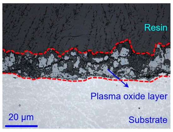
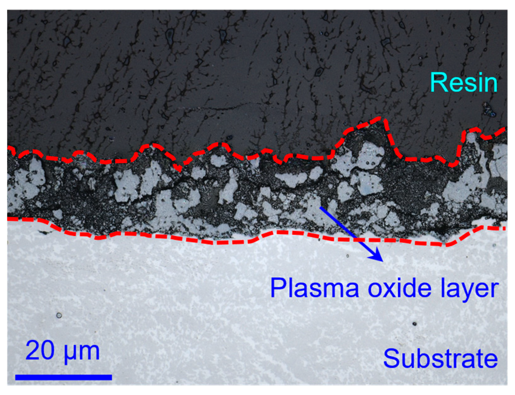
Subsequently, for cross-sectional observation, the workpiece was ground with SiC papers with successive grades, followed by polishing to mirror through chemical mechanical polishing. Using a confocal laser microscope (VK-X1000, Keyence, Osaka, Japan), the cross-sectional appearance of the workpiece with an oxide layer was observed and is shown in Figure 3. The thickness of the oxide layer lying between the two red dashed lines in Figure 3 was measured with the average values from twenty measurements. Under the optimal plasma oxidation parameters, the average thickness of the oxide layer was 15.86 μm.
Figure 3.
The cross-sectional appearance of the workpiece with the oxide layer.
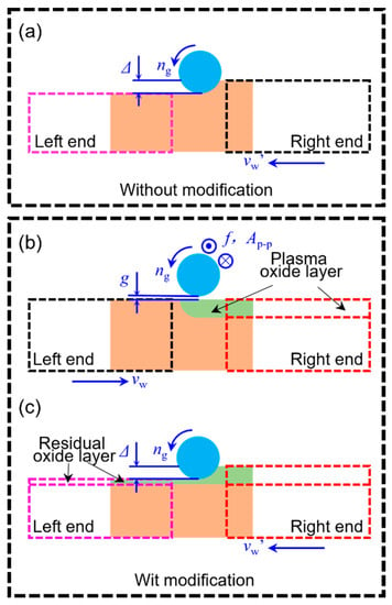
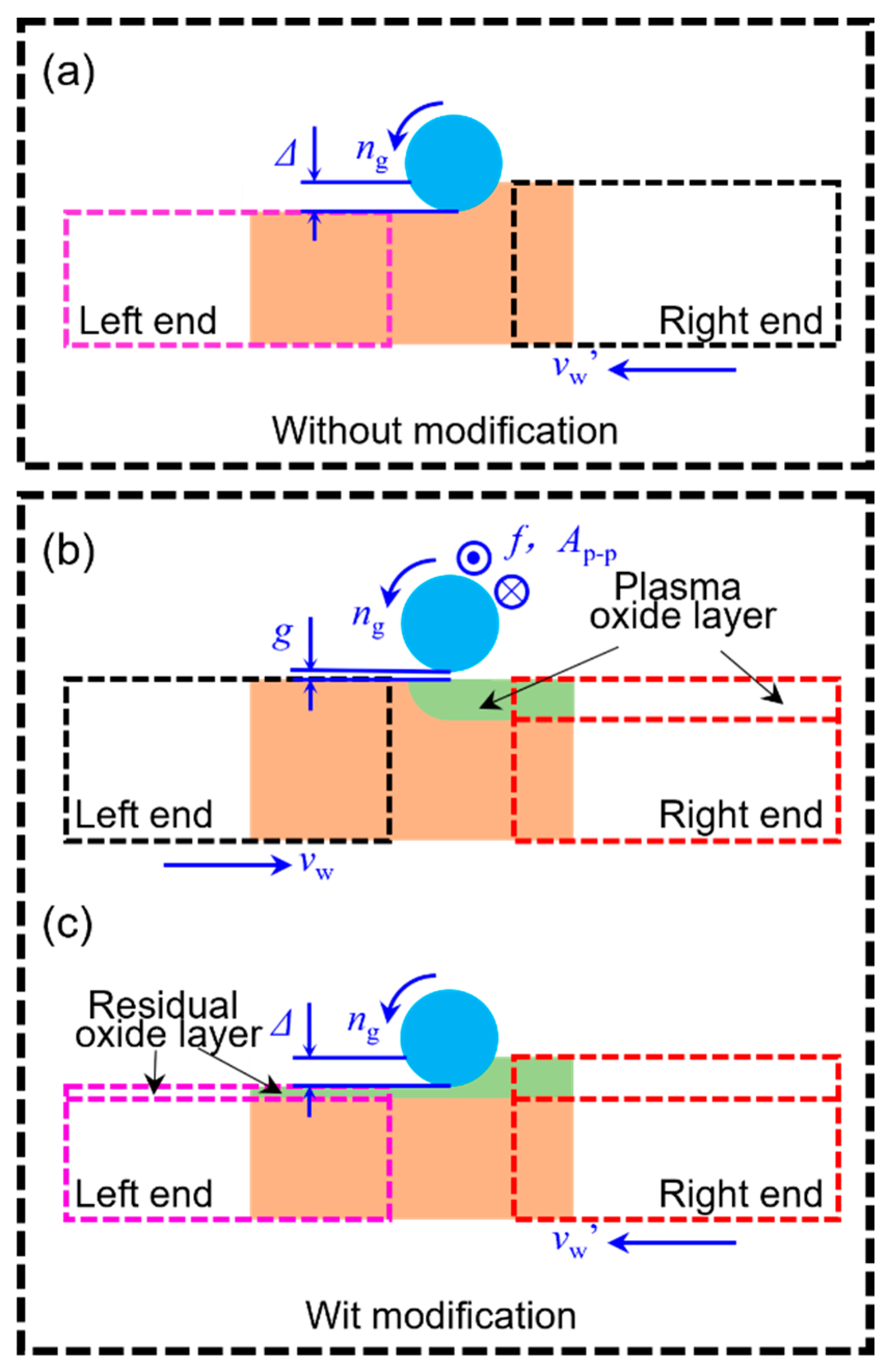
Figure 4 shows the schematic of one grinding pass for processing workpieces without and with modification. As shown in Figure 4a, during one grinding pass in the processing workpiece without modification, the grinding wheel rotating anticlockwise and the workpiece moving left operate the up-grinding to remove the titanium alloy substrate. Then, the workpiece moves right to the original position without grinding for the next operation of up-grinding. During one grinding pass in processing the workpiece with modification, as shown in Figure 4b, an oxide layer on the workpiece surface is prepared under the conditions of the grinding wheel rotating anticlockwise and the workpiece moving right. Then, as shown in Figure 4c, the grinding wheel rotating anticlockwise and the workpiece moving left operate the up-grinding to remove the oxide layer. The depth of cut is set at 10 μm, which is less than the average thickness of the plasma oxide layer of 15.86 μm (Figure 3), to ensure that only the oxide layer is cut by the abrasive grains. The test parameters used in these tests are listed in Table 1.
Figure 4.
Schematic of one grinding pass for processing the workpieces without (a) and with (b,c) modification.
Table 1.
Specific experimental parameters.
3. Results and Discussion
3.1. Properties of the Plasma Oxide Layer
The surface and cross-sectional morphologies, microhardness, and composition of the oxide layer were characterized before the grinding tests to explain the dynamic changes in wheel loading and the formation mechanism of the surface morphology of the ground workpiece.
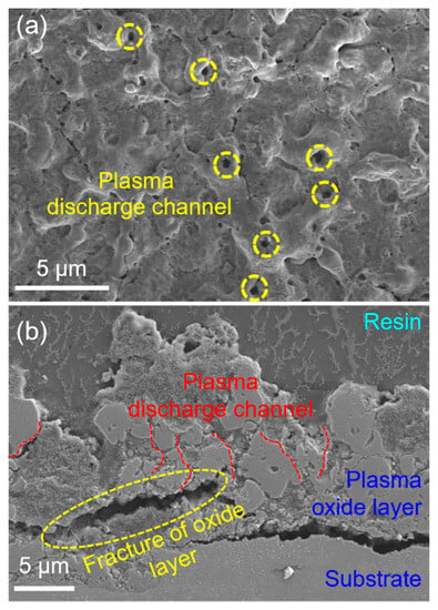
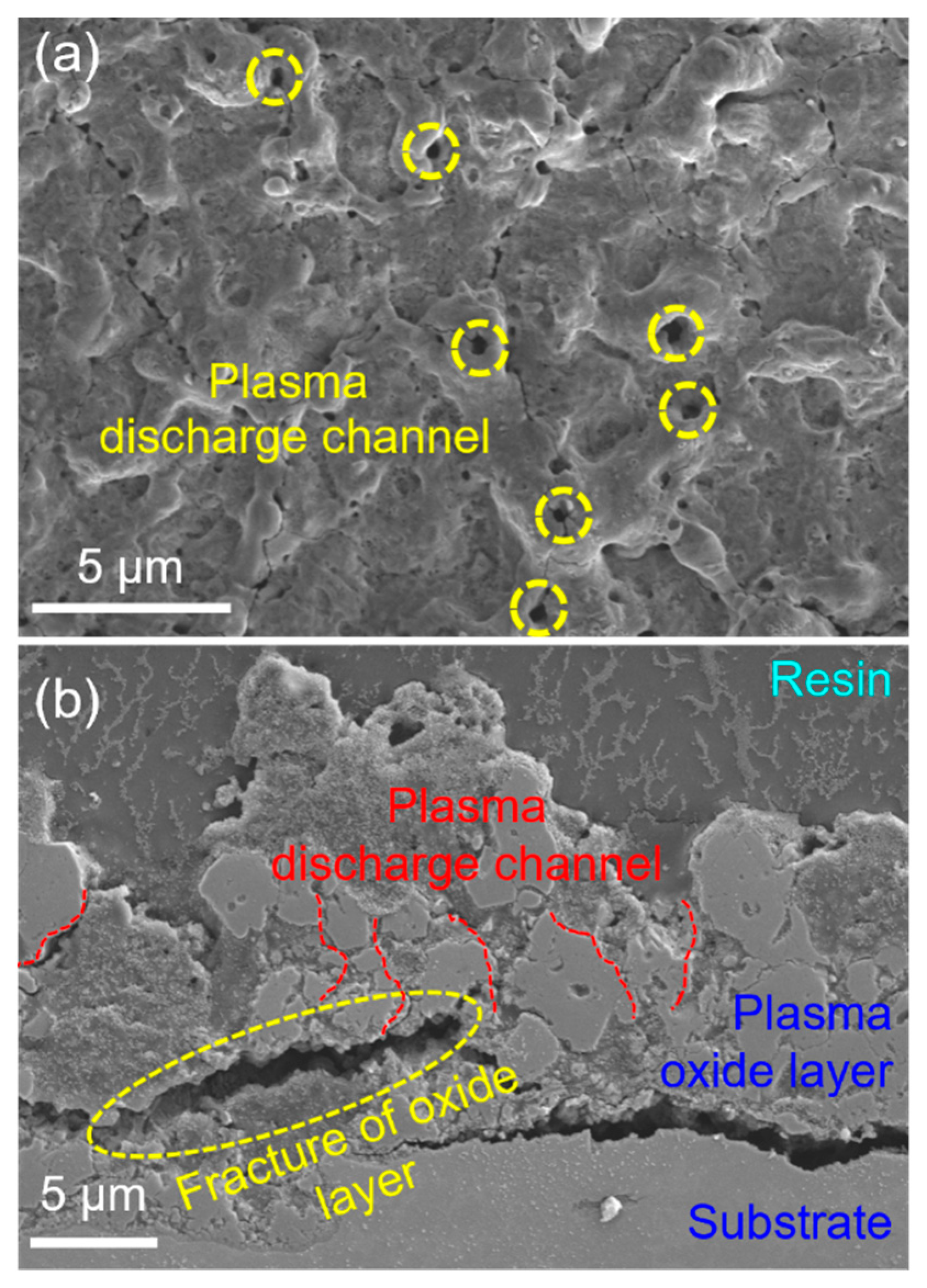
Figure 5 shows the surface and cross-sectional morphologies of the workpiece with an oxide layer. It can be seen from Figure 5a that microholes left by the plasma discharge channels [17] and microcracks probably caused by the release of thermal stress were simultaneously generated on the oxide layer surface. As shown in Figure 5b, many connected longitudinal microcracks along the direction of the plasma discharge channels were formed inside the oxide layer, which was caused by the continuous breakthrough of the oxide layer by the plasma discharge channels.
Figure 5.
SEM images of surface (a) and cross-section (b) morphologies of the workpiece with the oxide layer.
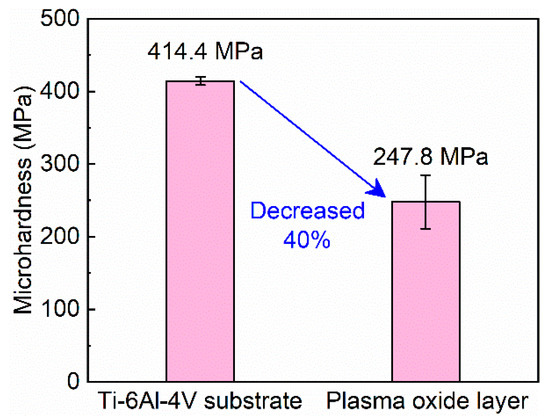
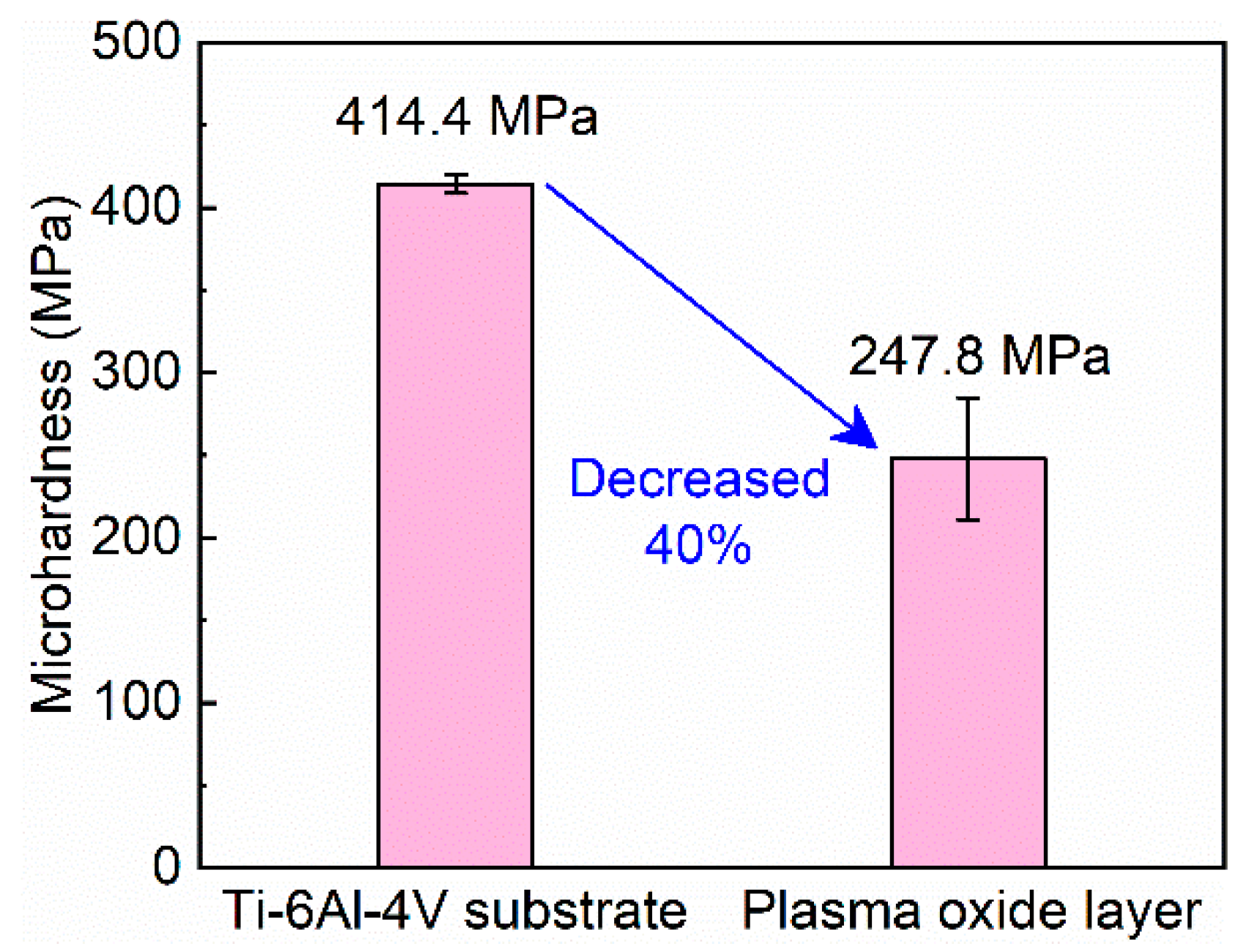
Subsequently, under the condition of the maximum load of 0.01 kg, Vickers microhardness was measured to characterize the mechanical strength of the titanium alloy substrate and oxide layer. As shown in Figure 6, the surface microhardness of the titanium alloy substrate was 414.4 ± 5.8 MPa, while that of the oxide layer was 247.8 ± 36.9 MPa, which decreased by 40%. In addition, compared with the titanium alloy substrate, the microhardness of the oxide layer fluctuates wildly. The oxide layer was probably uneven because of the microholes and -cracks (Figure 5), resulting in an extensive fluctuation range of microhardness.
Figure 6.
Microhardness of titanium alloy substrate and plasma oxide layer.
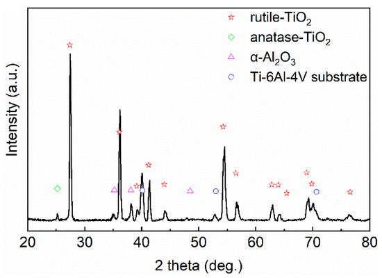
Further, the weight ratio of elements (Table 2) and phase composition (Figure 7) of the oxide layer were detected through EDS mapping and the X-ray diffractometer, respectively. As shown in Table 2, compared with the non-oxidized workpiece layer, the weight ratios of titanium, aluminum, and vanadium all decreased on the oxide layer surface. However, the weight ratio of oxygen increased significantly. The sum element content of sulfur and sodium (0.72 wt.%) was much lower than the weight ratio of the oxygen element (26.12 wt.%). These changes in the elements’ weight ratios indicated that the oxide layer should mainly be composed of the oxidation of the titanium alloy material rather than the deposition of the electrolyte [18]. As shown in Figure 7, the diffraction peaks corresponding to rutile TiO2, anatase TiO2, and α-Al2O3 appeared in the XRD pattern, indicating that the oxide layer contained rutile TiO2, anatase TiO2, and α-Al2O3 [19], which were consistent with the detection results of EDS mapping.
Table 2.
Elements’ weight ratios on the Ti-6Al-4V substrate and plasma oxide layer.
Figure 7.
XRD pattern of the plasma oxide layer.
3.2. Evolution of Wheel Loading on the Grinding Wheel Surface
In order to characterize the dynamic changes of wheel loading on the grinding wheel surface, chip adhesion in a random area (1300 μm × 1000 μm) selected from the grinding wheel surface was observed in succession after gradually increasing the grinding passes when workpieces were processed without and with an oxide layer.
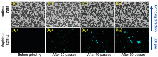
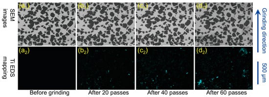
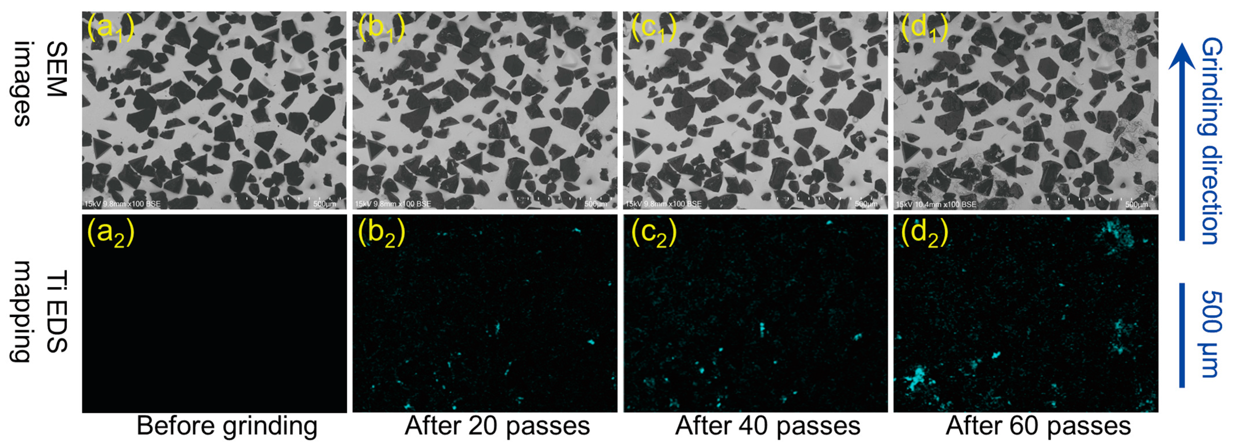
Figure 8 shows a typical appearance of the grinding wheel surface and the distribution of the titanium element adhered on the wheel surface without the oxide layer. Before grinding, as shown in Figure 8a1,a2, no titanium element was detected on the wheel surface. After 20 grinding passes, as shown in Figure 8b1,b2, some adhered chips with a small area appeared on the wheel surface. Then, after 40 grinding passes, as shown in Figure 8c1,c2, the area of each chip adhesion increased. Further, after 60 grinding passes, as shown in Figure 8d1,d2, a considerable increase in each adhesion area can be seen, and simultaneously new adhered chips appeared on the wheel surface, resulting in severe wheel loading.
Figure 8.
Wheel loading in the absence of the oxide layer: (a1–d1) appearance of the wheel surface and (a2–d2) EDS mapping of the titanium element.
Compared with grinding workpieces without the oxide layer, in the presence of the oxide layer, a slight chip adhesion appeared on the wheel surface after up to 40 grinding passes (Figure 9b2,c2). Then, after 60 grinding passes, though the area of each adhered chip increased, the grinding wheel surface still looked relatively clean (Figure 9d2), resulting in slight wheel loading.
Figure 9.
Wheel loading in the presence of the oxide layer: (a1–d1): appearance of the wheel surface and (a2–d2) EDS mapping of the titanium element.
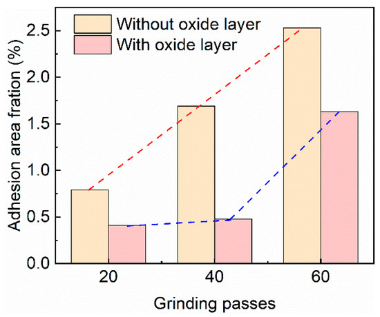
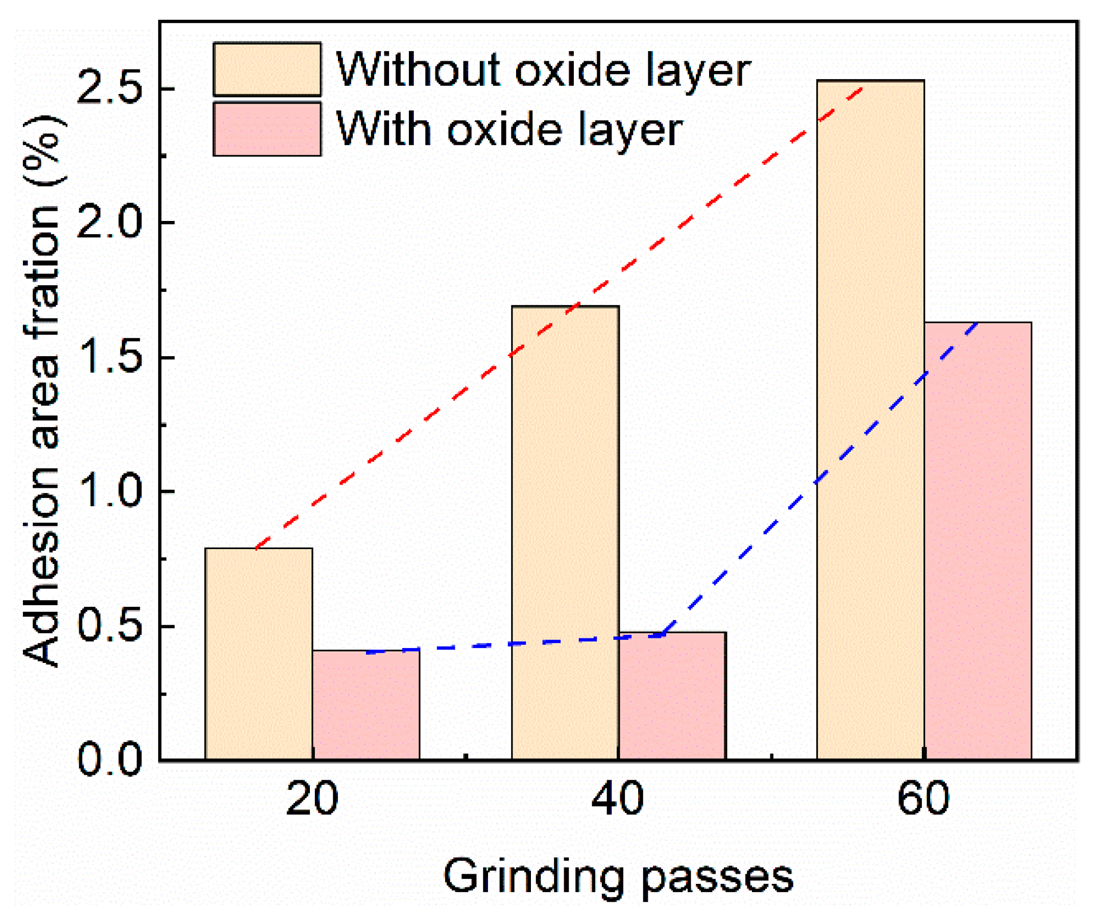
Subsequently, the grayscale conversion, scale bar setting, threshold adjustment, and area statistics of Figure 8b2–d2 and Figure 9b2–d2 were performed through Image J to obtain the overall occupied area fraction of chip adhesion [20], which is shown in Figure 10. As the grinding passes gradually increased, regardless of whether there was an oxide layer, the overall occupied area fraction of chip adhesion on the wheel surface showed an upward trend. However, the growth details varied with the absence and presence of an oxide layer. Specifically, in the absence of an oxide layer and with the grinding passes increasing from 20 to 40, and then to 60, the overall occupied area fraction of the chip adhesion on the wheel surface increased from 0.79% to 1.69%, and then to 2.53%, which presented an almost linear increase. In the presence of an oxide layer, after 20 and 40 grinding passes, the overall occupied area of the chip adhesion on the wheel surface accounted for 0.41% and 0.48%, respectively. Further, after 60 grinding passes, the overall occupied area of chip adhesion increased to 1.63%. It can be summarized that the overall occupied area fraction of chip adhesion remained stable in a short range of the grinding passes and then rose with an increase in the grinding passes. In addition, compared with grinding workpieces without a plasma oxide layer, the presence of the plasma oxide layer could lessen the occupied area fraction of the chip adhesion on the wheel surface by 48.1%, 71.6%, and 35.6%, respectively, after 20, 40, and 60 grinding passes.
Figure 10.
The effect of grinding passes on the overall occupied area of the chip adhesion on the wheel surface.
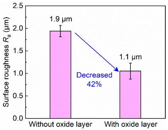
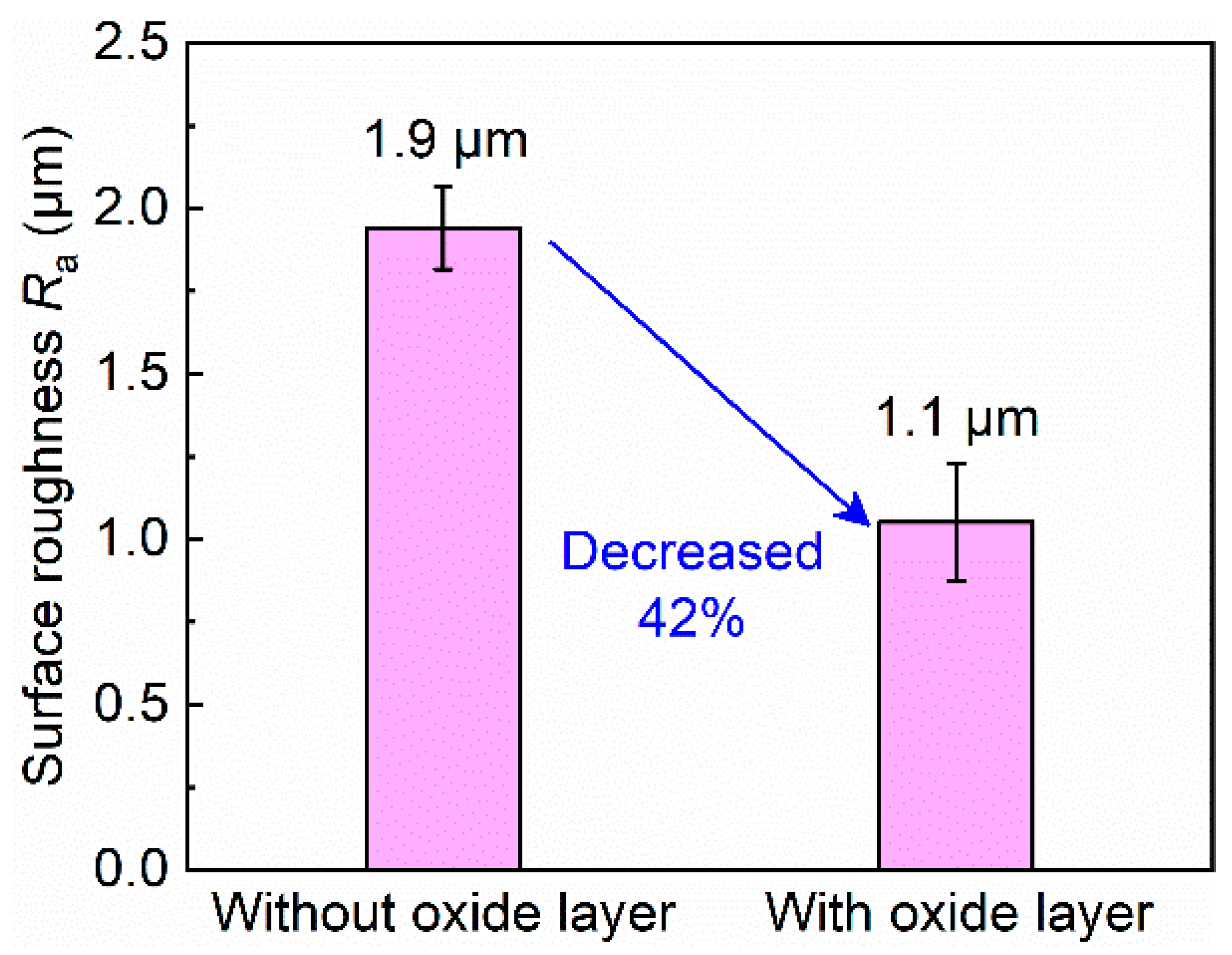
The surface roughness and grinding force were measured to clarify the significance of the wheel loading reduction after 60 grinding passes. Figure 11 shows the surface roughness of the ground workpiece without and with an oxide layer after 60 grinding passes. Compared with the ground workpiece without an oxide layer, the surface roughness Ra of the ground workpiece decreased from 1.9 μm to 1.1 μm, reduced by 42%, with the assistance of an oxide layer. The surface condition of the grinding wheel played a significant role in the surface roughness of the ground workpieces. As the grinding passes gradually increased in the grinding of the workpiece without an oxide layer, the overall area fraction of the chip adhesion increased in a straight line (Figure 10), increasing wheel loading, and therefore deteriorating the working surface of the grinding wheel. In this case, the grinding wheel with low cutting ability made the ground workpiece surface rough. However, in the grinding of the workpiece with an oxide layer, the overall area fraction of the chip adhesion remained unchanged before 40 grinding passes and then rose with the further increase in grinding passes (Figure 10), reducing wheel loading and maintaining the cutting ability of the grinding wheel. Hence, the surface roughness of the ground workpiece was improved.
Figure 11.
The surface roughness of the ground workpiece without and with the oxide layer after 60 grinding passes.
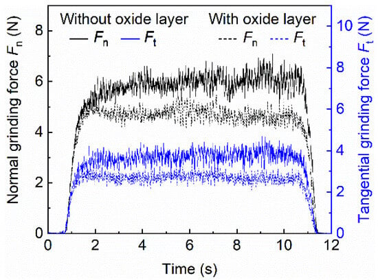
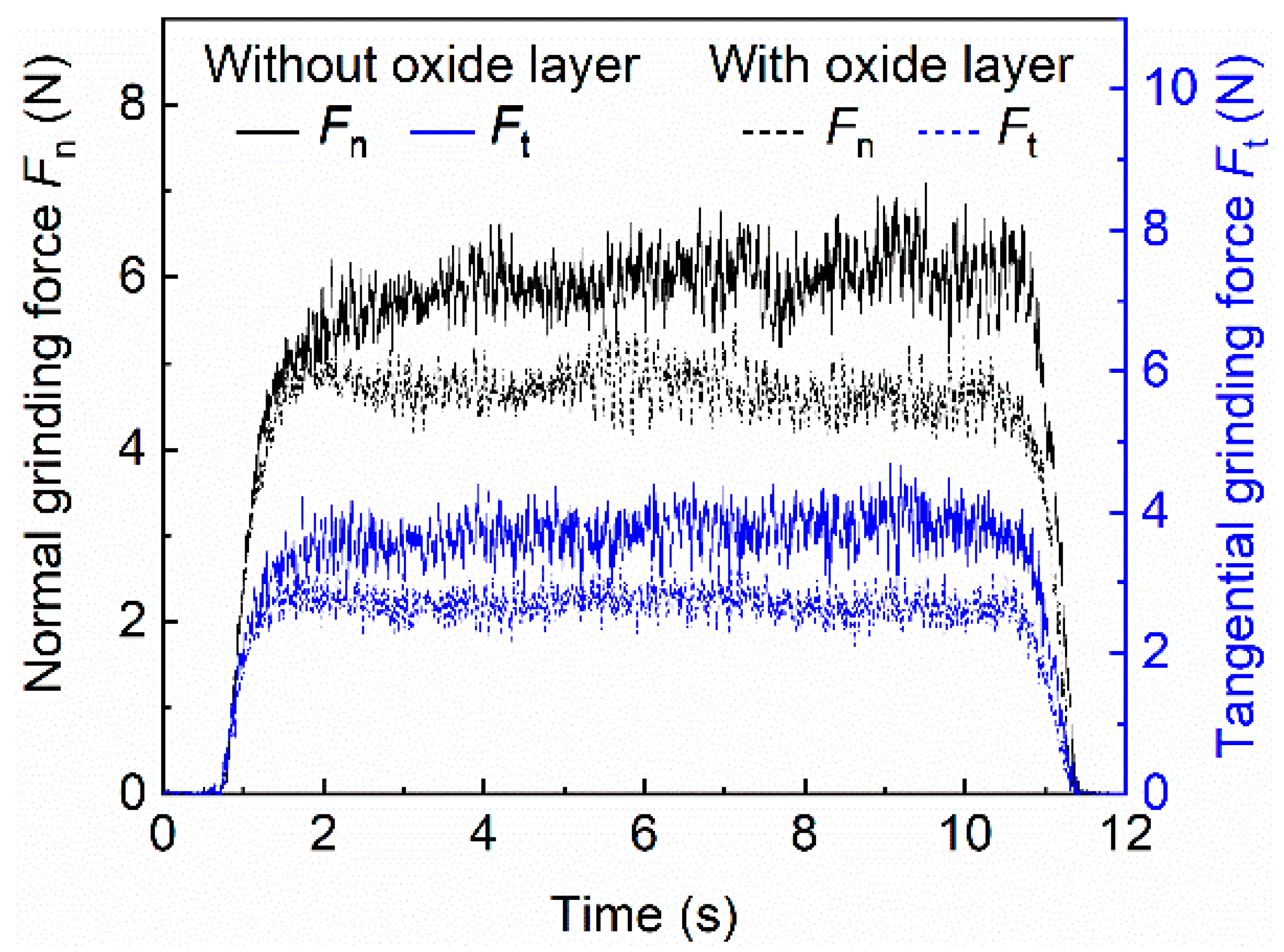
On the other hand, wheel loading has a significant effect on energy consumption during the grinding process. Hence, dynamic changes in the grinding forces were recorded during the 60th grinding pass in processing the workpiece without and with an oxide layer and are shown in Figure 12. In the presence of an oxide layer, the normal and tangential grinding forces both decreased compared with those obtained without an oxide layer. Specifically, the normal and tangential grinding forces decreased by 21% and 27%, respectively, indicating that a reduction in energy consumption occurred with the assistance of the oxide layer. Considering that the overall occupied area of chip adhesion decreased from 2.53% to 1.56% after 60 grinding passes (Figure 10), it can be inferred that a decrease in wheel loading with the assistance of an oxide layer had a significant effect on the grinding performance, i.e., improving the surface roughness Ra and reducing the grinding force.
Figure 12.
The dynamic changes of the grinding forces during the 60th grinding pass in processing the workpiece without and with an oxide layer.
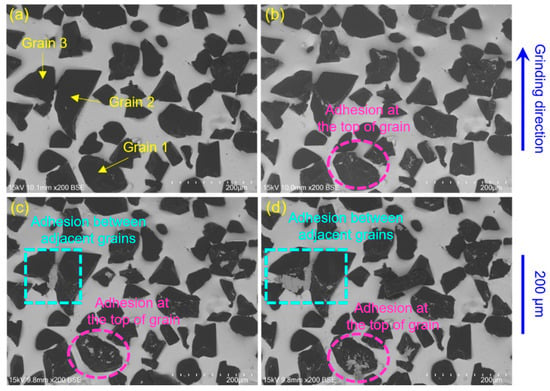
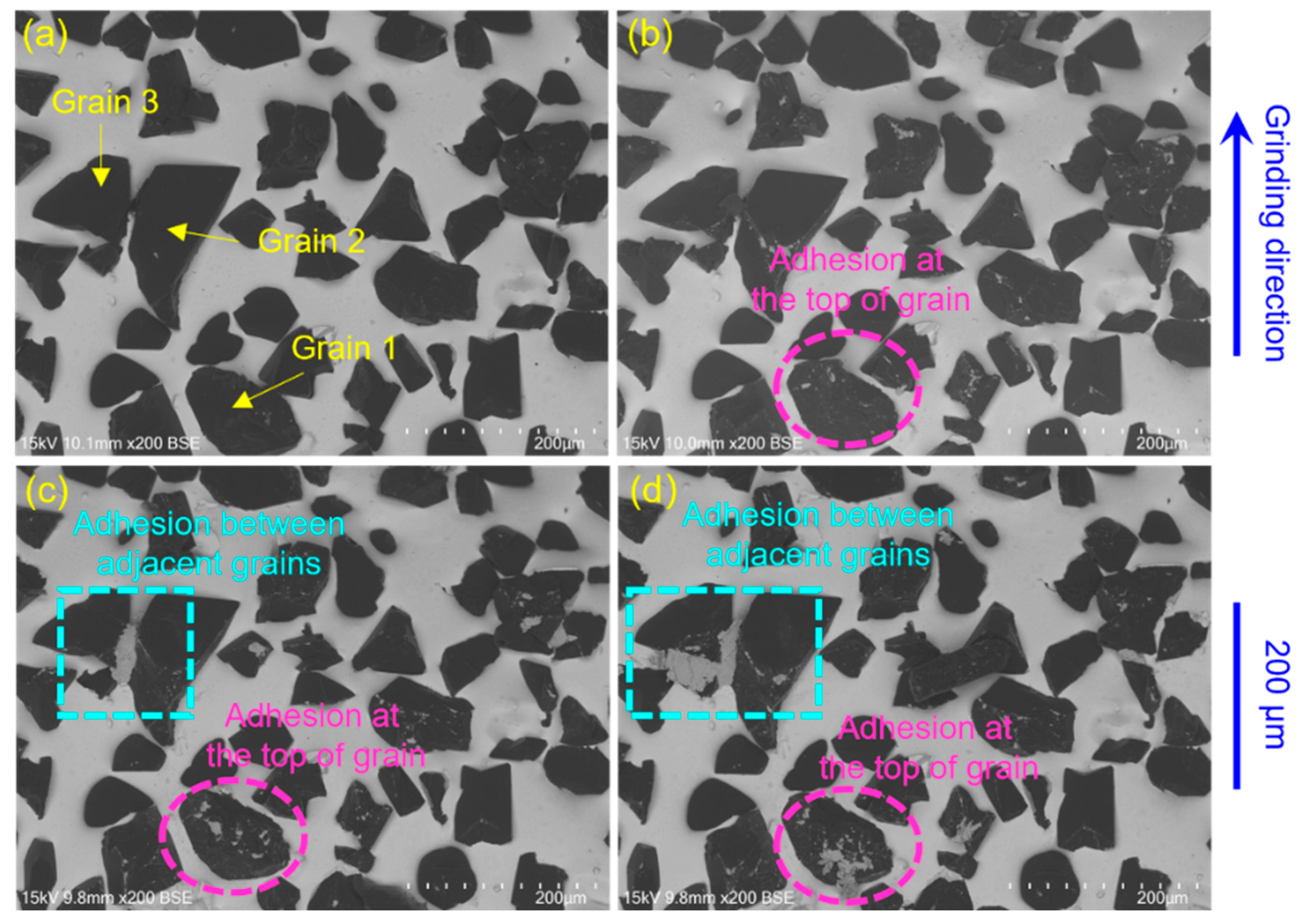
To explain the dynamic changes of wheel loading, the evolution behavior of the chip adhesion on the abrasive grains was observed in succession after gradually increasing the grinding passes. Figure 13 shows the chip adhesion evolution behaviors on the abrasive grains and the bonding without an oxide layer. As shown in Figure 13b–d, as the grinding passes increased from 20 to 60 times, the area of the adhered chip at the top of grain 1 gradually expanded and eventually covered almost all the cutting edges of grain 1. In addition, after 40 grinding passes, a bridge-like adhesion appeared between the adjacent grains 2 and 3 (Figure 13c), which is the original cause of clogging. Further, after 60 grinding passes, the bridge-like adhesion extended to the top of grain 3 and covered its cutting edges (Figure 13d). Hence, the combination with the severe chip adhesion at the top of grains and between adjacent grains made the overall occupied area fraction of chip adhesion on the wheel surface rise linearly with an increase in grinding passes, finally reaching 2.53% after 60 grinding passes. The results might be explained by a large amount of the heat produced in the grinding zone during the cutting action between the grains and titanium alloy material with a high microhardness of 414.4 ± 5.8 MPa (Figure 6), resulting in an enhancement of the ductility and chemical activity of the titanium alloy at a high temperature. As a result, cold welds were easily formed between the titanium alloy chips and the grains or bonding materials to stick to the wheel surface [21]. With the extension of the grinding distance, the areas of chip adhesion at the top of grains and between the adjacent grains gradually expanded, resulting in severe wheel loading [22].
Figure 13.
The evolution behaviors of chip adhesion on the abrasive grains in the absence of the oxide layer: (a) before grinding and after (b) 20, (c) 40, and (d) 60 grinding passes.
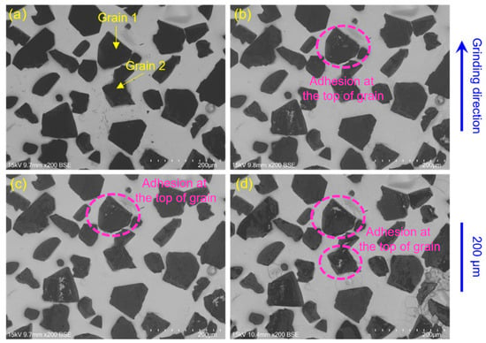
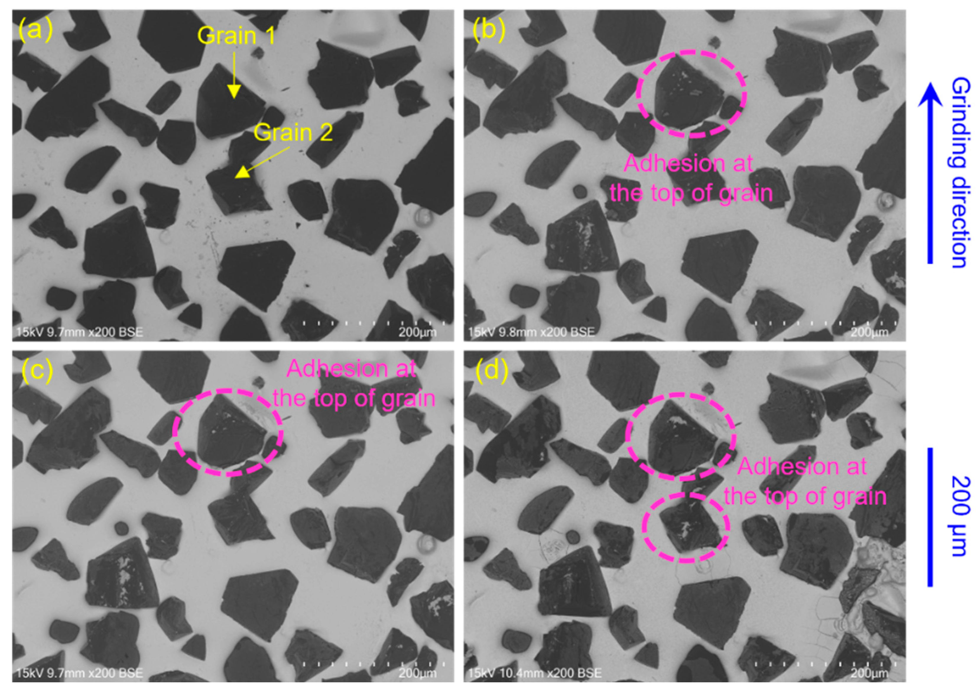
Figure 14 shows the evolution behaviors of chip adhesion on the abrasive grains in the presence of an oxide layer. As the grinding passes increased from 20 to 60 times, the area of the adhered chip at the top of grain 1 slowly increased; therefore, the cutting edges of grain 1 were not fully covered (Figure 14b–d), indicating that grain 1 still had cutting ability. A slight chip adhesion appeared at the top of grain 2 after up to 60 grinding passes (Figure 14d). Clogging caused specifically by the bridge-like adhesion was not found on the wheel surface. Hence, only the slight chip adhesion at the top of the grains caused the overall occupied area fraction of the chip adhesion on the wheel surface to remain stable and then to rise, reaching only 1.63% after 60 grinding passes. The results might be explained by the reduction in the heat produced in the grinding zone during the cutting action between the grains and the oxide layer with a lower microhardness of 247.8 ± 36.9 MPa (Figure 6). Moreover, the oxide layer with microholes and -cracks (Figure 5) is mainly composed of TiO2 with a fracture toughness of 3.2 MPa·m1/2 and Al2O3 with a fracture toughness of 5 MPa·m1/2 (Figure 7), both less than 10% of the titanium alloy substrate (55 MPa·m1/2) [23]. The loose and fragile oxide layer probably has lower ductility than the titanium alloy substrate. Hence, cold welds were not easily formed between the plasma oxidized material and the grains or bonding materials during grinding [21], effectively inhibiting wheel loading.
Figure 14.
The evolution behaviors of chip adhesion on the abrasive grains in the presence of the oxide layer: (a) before grinding and after (b) 20, (c) 40, and (d) 60 grinding passes.
3.3. Ground Workpiece Surface Quality
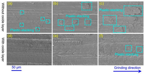
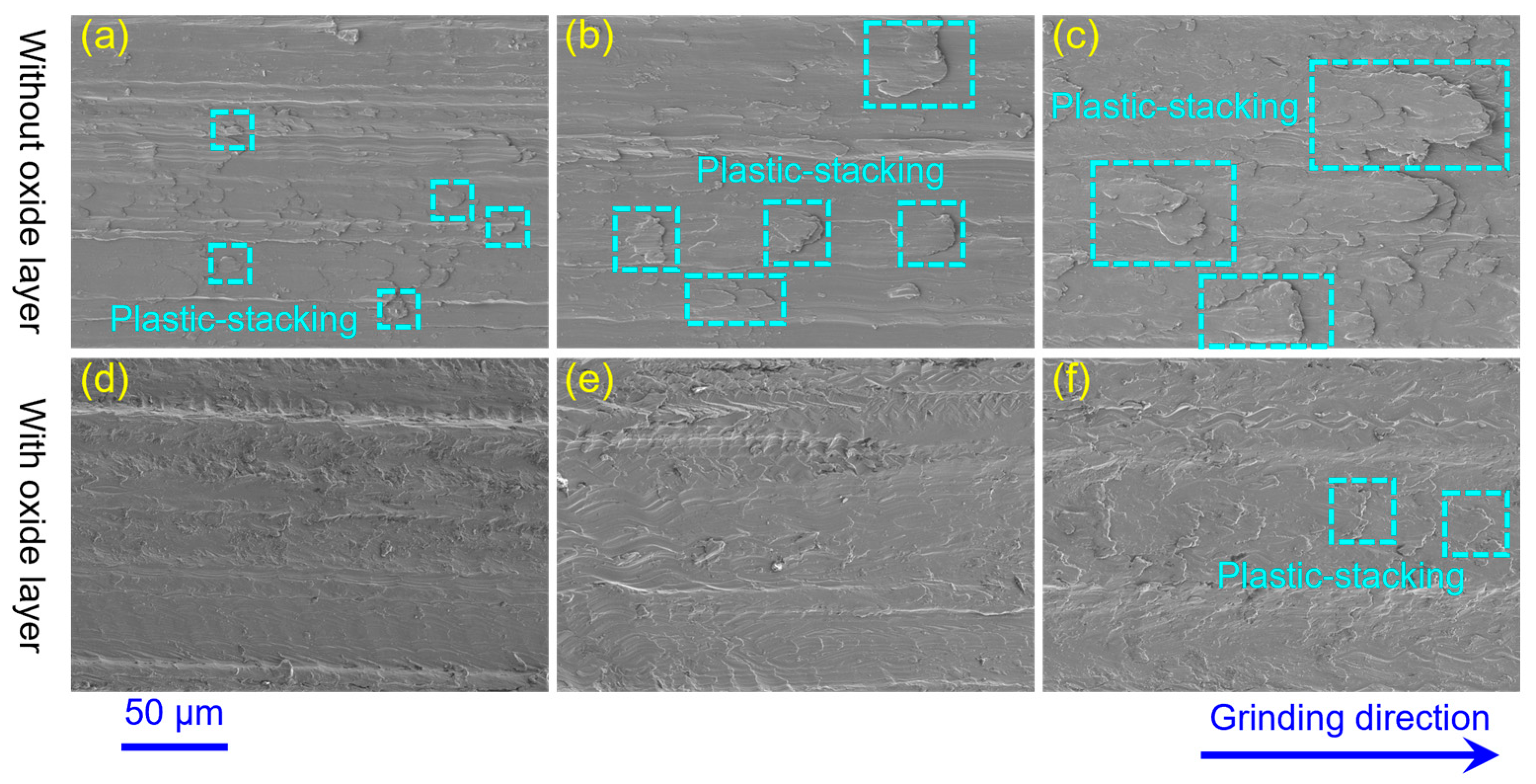
To clarify the effect of wheel loading on the surface quality, the ground surface morphologies of the workpieces without and with an oxide layer were observed through SEM after gradually increasing the grinding passes and are shown in Figure 15. It should be noted that in the 20th, 40th, and 60th grinding pass in processing the workpieces with an oxide layer, the plasma and ultrasonic power supplies were both turned down. Other processing parameters were kept unchanged to ensure that the residual oxide layer from the last grinding pass was completely removed. In the absence of an oxide layer, as shown in Figure 15a–c, the fish-scale plastic-stacking with increased volume appeared and finally occupied the whole ground surface as the grinding passes increased. Differently, in the presence of an oxide layer, as shown in Figure 15d–f, no plastic-stacking was observed on the ground workpiece surface after up to 40 grinding passes. Further, after experiencing 60 grinding passes, the fish-scale plastic-stacking with a small volume began to appear on the ground surface of the workpiece.
Figure 15.
Ground surface morphologies of the workpieces after (a,d) 20, (b,e) 40, and (c,f) 60 grinding passes without and with an oxide layer.
The abrasive grains were in contact with the titanium alloy substrate when processing the workpieces without an oxide layer. The titanium alloy material with high ductility and chemical activity at a high temperature was easy to weld on to the grains and/or wheel bonding [21]. After 20 grinding passes, the overall occupied area fraction of chip adhesion is 0.79% (Figure 8b2). Under this condition of slight wheel loading, chip adhesion appeared at the top of grains (Figure 13b), which increased the rubbing and plowing effects between the abrasive grains and the titanium alloy substrate with a high ductility and microhardness of 414.4 ± 5.8 MPa (Figure 6) [24]. Hence, some fish-scale plastic-stacking appeared on the ground workpiece surface along the grinding direction (Figure 15a) [25]. Then, after 40 grinding passes, the overall occupied area fraction of chip adhesion increased to 1.69% (Figure 8c2). Under this moderate wheel loading, the area of chip adhesion at the top of the grains expanded, and a part of the cutting edges of the grains were covered (Figure 13c), resulting in an increased contact area between the grains and the titanium alloy substrate, which might make the rubbing and plowing effects between the grains and the work material more prominent. Therefore, the volume of fish-scale plastic-stacking on the ground workpiece surface increased (Figure 15b). Further, after 60 grinding passes, the overall occupied area fraction of chip adhesion was further increased to 2.53% (Figure 8d2). In this case of severe wheel loading, combined with the further expansion of the adhered chips at the top of the abrasive grains, the bridge-like adhesion between adjacent abrasive grains (Figure 13d) caused a coverage of almost all the cutting edges of abrasive grains, which made the grinding wheel lose its cutting ability. Hence, the mutual extrusion between the adhered titanium alloy chips on the wheel surface and the titanium alloy substrate was dominant, thus forming a larger volume of plastic-stacking on the ground workpiece surface (Figure 15c).
Conversely, the abrasive grains were in contact with the plasma-oxidized material when processing the workpieces with an oxide layer. The oxide layer containing the TiO2 and Al2O3 with low ductility has a loose and fragile structure, which probably constrains the oxidized material from welding on to the abrasive grains and/or wheel bonding. After 40 grinding passes, the overall occupied area fraction of chip adhesion was only about 0.48% (Figure 9c2). In this case of almost no wheel loading, only a slight adhesion appeared at the top of the grains (Figure 14c), which hardly reduced the cutting ability of the abrasive grains. Hence, the cutting effect of an oxide layer with a low ductility and microhardness of 247.8 ± 36.9 MPa (Figure 6) was dominated by grains with sharp cutting edges, inhibiting the formation of plastic-stacking (Figure 15e). Further, after 60 grinding passes, the overall occupied area fraction of chip adhesion increased to 1.63% (Figure 9d2). Under this moderate wheel loading, though the expansion of chip adhesion covered a part of the cutting edges of the grains, the oxide layer with low ductility and microhardness was easy to cut and consequently remove. Hence, only some plastic-stacking with a small volume appeared on the ground workpiece surface (Figure 15f).
4. Conclusions
The effect of the absence and presence of an oxide layer on the wheel loading of the grinding wheel surface was experimentally investigated. The dominant findings are summarized as follows:
- (1)
- The surface microhardness of the oxide layer decreased by 40.2% compared with that of the titanium alloy substrate. The loose and fragile oxide layer, mainly containing TiO2 and Al2O3 with low fracture toughness, could reduce wheel loading and improve the ground surface quality.
- (2)
- After 60 grinding passes, an oxide layer caused a 35.6% decline in the overall occupied area fraction of chip adhesion compared with the absence of an oxide layer. A decrease in wheel loading improved the ground surface roughness by 45.9% and decreased the grinding force by about 25%.
- (3)
- In the absence of an oxide layer, the abrasive grains covered with adhered chips lost their cutting ability, causing the production of plastic-stacking under the mutual extrusion between the adhered chips and the titanium alloy substrate. However, in the presence of an oxide layer, the abrasive grains with sharp cutting edges cut the oxide layer to constrain plastic-stacking production, resulting in an evenly ground surface.
Author Contributions
Conceptualization, Y.W. and H.W.; methodology, Y.W.; software, X.Y.; validation, H.W., X.Y. and Z.C.; formal analysis, S.Z.; investigation, J.Z.; resources, Y.W.; data curation, H.W. and Z.C.; writing—original draft preparation, H.W.; writing—review and editing, Y.W.; visualization, X.Y.; supervision, Y.W.; project administration, J.Z.; funding acquisition, Q.W. All authors have read and agreed to the published version of the manuscript.
Funding
This research was funded by the National Nature Science Foundation of China (Grant No. 51975269), the Key projects of the Ministry of Science and Technology of China (Grant No. 2021YFF0700900), and the Shenzhen Key Technology Breakthrough Project (Grant No. JSGG20220831093200001).
Data Availability Statement
Not applicable.
Conflicts of Interest
The authors declare no conflict of interest.
References
- Liu, M.; Li, C.; Yang, M.; Gao, T.; Wang, X.; Cui, X.; Zhang, Y.; Said, Z.; Sharma, S. Mechanism and enhanced grindability of cryogenic air combined with biolubricant grinding titanium alloy. Tribol. Int. 2023, 187, 108704. [Google Scholar] [CrossRef] [Scilit]
- Singh, P.K.; Kumar, S.; Jain, P.K. Effect of cryogenic grinding on surface characteristics of additively manufactured Ti-6Al-4V alloy. Surf. Topogr. Metrol. Prop. 2023, 11, 015014. [Google Scholar] [CrossRef] [Scilit]
- Cui, X.; Li, C.; Zhang, Y.; Said, Z.; Debnath, S.; Sharma, S.; Ali, H.M.; Yang, M.; Gao, T.; Li, R. Grindability of titanium alloy using cryogenic nanolubricant minimum quantity lubrication. J. Manuf. Process. 2022, 80, 273–286. [Google Scholar] [CrossRef] [Scilit]
- Zhou, K.; Xiao, G.; Xu, J.; Huang, Y. Wear evolution of electroplated diamond abrasive belt and corresponding surface integrity of Inconel 718 during grinding. Tribol. Int. 2023, 177, 107972. [Google Scholar] [CrossRef] [Scilit]
- Guo, G.; Liu, Z.; An, Q.; Chen, M. Experimental investigation on conventional grinding of Ti-6Al-4V using SiC abrasive. Int. J. Adv. Manuf. Technol. 2011, 57, 135–142. [Google Scholar] [CrossRef] [Scilit]
- Pashmforoush, F.; Delir Bagherinia, R. Influence of water-based copper nanofluid on wheel loading and surface roughness during grinding of Inconel 738 superalloy. J. Clean. Prod. 2018, 178, 363–372. [Google Scholar] [CrossRef] [Scilit]
- Gupta, M.K.; Song, Q.; Liu, Z.; Sarikaya, M.; Mia, M.; Jamil, M.; Singla, A.K.; Bansal, A.; Pimenov, D.Y.; Kuntoğlu, M. Tribological performance based machinability investigations in cryogenic cooling assisted turning of α-β titanium Alloy. Tribol. Int. 2021, 160, 107032. [Google Scholar] [CrossRef] [Scilit]
- Elanchezhian, J.; Pradeep Kumar, M.; Manimaran, G. Grinding titanium Ti-6Al-4V alloy with electroplated cubic boron nitride wheel under cryogenic cooling. J. Mech. Sci. Technol. 2015, 29, 4885–4890. [Google Scholar] [CrossRef] [Scilit]
- Aurich, J.C.; Kirsch, B.; Herzenstiel, P.; Kugel, P. Hydraulic design of a grinding wheel with an internal cooling lubricant supply. Prod. Eng. 2010, 5, 119–126. [Google Scholar] [CrossRef] [Scilit]
- Li, X. Application of self-inhaling internal cooling wheel in vertical surface grinding. Chin. J. Mech. Eng. 2014, 27, 86–91. [Google Scholar] [CrossRef] [Scilit]
- Zhou, K.; Xie, F.; Wu, X.; Wang, S. Fretting wear behavior of nano ZrO2 doped plasma electrolytic oxidation composite coatings on TC21 titanium alloy. Surf. Coat. Technol. 2021, 421, 127429. [Google Scholar] [CrossRef] [Scilit]
- Pesode, P.; Barve, S. Surface modification of titanium and titanium alloy by plasma electrolytic oxidation process for biomedical applications: A review. Mater. Today Proc. 2021, 46, 594–602. [Google Scholar] [CrossRef] [Scilit]
- Li, Y.; Wu, C.; Chen, M. Numerical analysis of the heat-pressure characteristics in ultrasonic vibration assisted plasma arc. J. Appl. Phys. 2020, 128, 114903. [Google Scholar] [CrossRef] [Scilit]
- González, H.; Calleja, A.; Pereira, O.; Ortega, N.; López de Lacalle, L.; Barton, M. Super Abrasive Machining of Integral Rotary Components Using Grinding Flank Tools. Metals 2018, 8, 24. [Google Scholar] [CrossRef] [Scilit]
- Suárez, A.; Veiga, F.; de Lacalle, L.N.L.; Polvorosa, R.; Lutze, S.; Wretland, A. Effects of Ultrasonics-Assisted Face Milling on Surface Integrity and Fatigue Life of Ni-Alloy 718. J. Mater. Eng. Perform. 2016, 25, 5076–5086. [Google Scholar] [CrossRef] [Scilit]
- Celaya, A.; Lopez de Lacalle, L.N.; Campa, F.J.; Lamikiz, A. Ultrasonic Assisted Turning of mild steels. Int. J. Mater. Product. Technol. 2009, 37, 60–70. [Google Scholar] [CrossRef] [Scilit]
- Cheng, Y.-L.; Wu, X.-Q.; Xue, Z.-G.; Matykina, E.; Skeldon, P.; Thompson, G.E. Microstructure, corrosion and wear performance of plasma electrolytic oxidation coatings formed on Ti–6Al–4V alloy in silicate-hexametaphosphate electrolyte. Surf. Coat. Technol. 2013, 217, 129–139. [Google Scholar] [CrossRef] [Scilit]
- Li, Q.; Yang, W.; Liu, C.; Wang, D.; Liang, J. Correlations between the growth mechanism and properties of micro-arc oxidation coatings on titanium alloy: Effects of electrolytes. Surf. Coat. Technol. 2017, 316, 162–170. [Google Scholar] [CrossRef] [Scilit]
- Yao, Z.; Jiang, Y.; Jia, F.; Jiang, Z.; Wang, F. Growth characteristics of plasma electrolytic oxidation ceramic coatings on Ti–6Al–4V alloy. Appl. Surf. Sci. 2008, 254, 4084–4091. [Google Scholar] [CrossRef] [Scilit]
- Wu, H.; Duan, W.; Sun, L.; Zeng, J.; Li, S.; Wang, Q.; Wu, Y.; Chen, Y. Effect of ultrasonic vibration on the machining performance and mechanism of hybrid ultrasonic vibration/plasma oxidation assisted grinding. J. Manuf. Process. 2023, 94, 466–478. [Google Scholar] [CrossRef] [Scilit]
- Xu, X.; Yu, Y.; Huang, H. Mechanisms of abrasive wear in the grinding of titanium (TC4) and nickel (K417) alloys. Wear 2003, 255, 1421–1426. [Google Scholar] [CrossRef] [Scilit]
- Gift, F.C., Jr.; Misiolek, W.Z.; Force, E., II. Mechanics of Loading for Electroplated Cubic Boron Nitride (CBN) Wheels During Grinding of a Nickel-Based Superalloy in Water-Based Lubricating Fluids. J. Tribol. 2004, 126, 795–801. [Google Scholar] [CrossRef] [Scilit]
- Davis, J.R. Metals Handbook: Desk Edition; CRC Press: Boca Raton, FL, USA, 1998. [Google Scholar]
- Malkin, S. Grinding Technology: Theory and Applications of Machining with Abrasives; Industrial Press: New York, NY, USA, 1989. [Google Scholar]
- Zhang, Y.; Li, C.; Ji, H.; Yang, X.; Yang, M.; Jia, D.; Zhang, X.; Li, R.; Wang, J. Analysis of grinding mechanics and improved predictive force model based on material-removal and plastic-stacking mechanisms. Int. J. Mach. Tools Manuf. 2017, 122, 81–97. [Google Scholar] [CrossRef] [Scilit]

Disclaimer/Publisher’s Note: The statements, opinions and data contained in all publications are solely those of the individual author(s) and contributor(s) and not of MDPI and/or the editor(s). MDPI and/or the editor(s) disclaim responsibility for any injury to people or property resulting from any ideas, methods, instructions or products referred to in the content. |
© 2023 by the authors. Licensee MDPI, Basel, Switzerland. This article is an open access article distributed under the terms and conditions of the Creative Commons Attribution (CC BY) license (https://creativecommons.org/licenses/by/4.0/).