Article

Influence Analysis of Lubricant Recesses on the Working Capacity of the Bridge Span Spherical Bearing

Department of Computational Mathematics, Mechanics and Biomechanics, Perm National Research Polytechnic University, 614990 Perm, Russia
*
Author to whom correspondence should be addressed.
Lubricants 2022, 10(11), 283; https://doi.org/10.3390/lubricants10110283
Submission received: 16 October 2022 / Revised: 24 October 2022 / Accepted: 25 October 2022 / Published: 28 October 2022
(This article belongs to the Special Issue Friction and Lubrication of Sliding Bearings, Volume II)

Abstract

:
The load on transport and logistics systems is increasing every year. This is due to car park growth around the world. Thus, increasing bridge structure durability is an urgent task for bridge-building companies. This study analyses the contact deformation of spherical bearing elements through an anti-friction polymer layer with different geometrical configurations of recesses for the lubricant, i.e., annular grooves and spherical holes. The material of the anti-friction layer (a modified polytetrafluoroethylene (PTFE)) is modelled within the framework of the deformation theory of plasticity. The procedure of automating the numerical model construction depends on the input parameters, including the thickness of the layer, the basic geometrical parameters of the recesses for the lubricant, and the distance between the rows of recesses, etc. The influence of the arrangement of filling sliding anti-friction layers on recesses for lubricants in the form of spherical holes on the contact deformation behaviour of bridge bearings has been considered. The reduction of lubricant volume in the sliding anti-friction layer with the geometry of recesses in the form of spherical holes ranges from 26 to 48.4%, depending on the filling scheme, has been found. In this case, structures with lubrication recesses in the form of spherical holes have several advantages, including a more uniform distribution of contact parameters in the interface areas of the steel plates with the anti-friction layer, reduction of the maximum level of the plastic deformation intensity, displacements along the normal relative to the free end of the sliding layer, and the settlement of the bearing.

1. Introduction

1.1. Research Objectives

The study’s purpose was the comparison of the spherical bearing of bridge performance with the recesses for lubricants of different geometries and the influence analysis of the filling scheme lubricant recesses of the polymer layer.
Research objectives:
  • The creation of a numerical algorithm for the automated creation of a bearing parametrized model with recesses for lubrication of different geometries and filling schemes to solve and process the numerical solution results.
  • An evaluation of the influence of recesses with a lubricant on the structure performance.
  • The identification of quantitative and qualitative patterns of frictional contacts of the bearing steel elements with an anti-friction layer, taking into account the recesses with a lubricant.

1.2. Problem Context and Description

In the modern mechanics of deformable solids, modelling the behaviour of machines, technical systems, processes, and phenomena requires the various coupling mechanisms of subsystems (the elements) of the object under study [1,2,3] to be considered. Such elements most commonly refer to friction or friction mechanical systems [2] that operate within the framework of contact interaction mechanics, including bearings [4,5], sliding supports [6,7], gears, or chain gears [8,9,10]. The foundations of contact interaction mechanics were laid at the end of the XIX century by Heinrich Hertz and were widely developed in the works of Russian and foreign scientists (such as Alexandrov V.M., Goryacheva I.G., Johnson K., and Kendal K.). At present, several directions of contact interaction mechanics development can be distinguished:
  • The mathematical description and modelling of contact problems given the nature of machining mating surfaces, multilayered media, indenter geometry, etc. [11,12,13].
  • The modelling of processes and phenomena using contact interactions [14,15].
  • The modelling of contact interactions in the subsystems of real mechanisms, machines, equipment, and technological complexes [2,4,6,8,16,17,18].
The expansion of the theoretical foundations and practical methods for solving the problems of contact interaction mechanics has led to the development of efficient numerical methods for modelling contact problems based on the finite element method (FEM) [19,20]. Studies using modern engineering analysis software systems, such as ANSYS, ABAQUS, Nastran, etc., have become widespread. The development of efficient numerical methods impacts the timing and quality of problem-solving in many branches of industries and engineering. In [21], it is noted that it is insufficient to use only building codes in the analysis of the serviceability of transport system elements, including sliding supports or bridge span bearings. It can be noted that the FEM has found widespread practical applications in the study of the response of bearings to external loads [22,23,24].
Currently, there are a large number of challenges in the development of scientific and technological progress in the transport industry [25,26]. Due to the rapid growth of vehicle fleets, the load on transport and logistics systems is increasing [25,27], which leads to increased requirements for the performance characteristics of bridge structure elements [27,28]. Many authors considered the serviceability of different elements of transport systems, intending to increase the maintenance-free operation of critical structural elements [24,29,30,31,32,33,34,35]. In [6,36], the basic directions of research were considered within the framework of the rationalization of the geometrical configurations of critical elements of bridge structures (the bridge bearings), which absorb vertical and horizontal loads from the bridge span, as well as the external influences. One of the topical areas of research is the analysis of the influence of sliding surface lubrication recesses composed of polymeric materials. In this study, a numerical simulation of the lubrication recesses in the spherical sliding surface of the bridge span bearing surfaces is implemented. The influence of the geometry and location of the recesses on the deformation behaviour of the bridge bearing structure is evaluated.

2. Materials and Methods

2.1. Model

The object of the study is a spherical bearing, L-100, manufactured by “AlfaTech” (Perm, Russia). Figure 1 shows a simplified calculation diagram of the bearing; 1 is a steel plate with a polished spherical segment, 2 is a steel plate with a cut-out for the spherical sliding layer of the polymeric material, and 3 is an anti-friction polymeric layer. In the simplified model, no recesses are shown in the lubricant layer applied to the contact surface S K 1 .
Within the simulation, a quarter of the contact assembly designs were considered, and the discarded parts were replaced with symmetry conditions. On the surface S 1 , a load of ~55.5 MPa was applied, which is equivalent to the safe pressure from the bridge span of a bearing of a given size when bending is forbidden, and vertical displacements are forbidden on the surface S 2 . At the interface of the steel elements with an anti-friction layer S K 1 S K 3 , friction contact was implemented with an unknown nature of contact status distribution (i.e., no contact, sliding, and adhesion). The general mathematical formulation of the problem was provided in [37] and was supplemented by considering large deformations in the volume of the sliding anti-friction layer material.
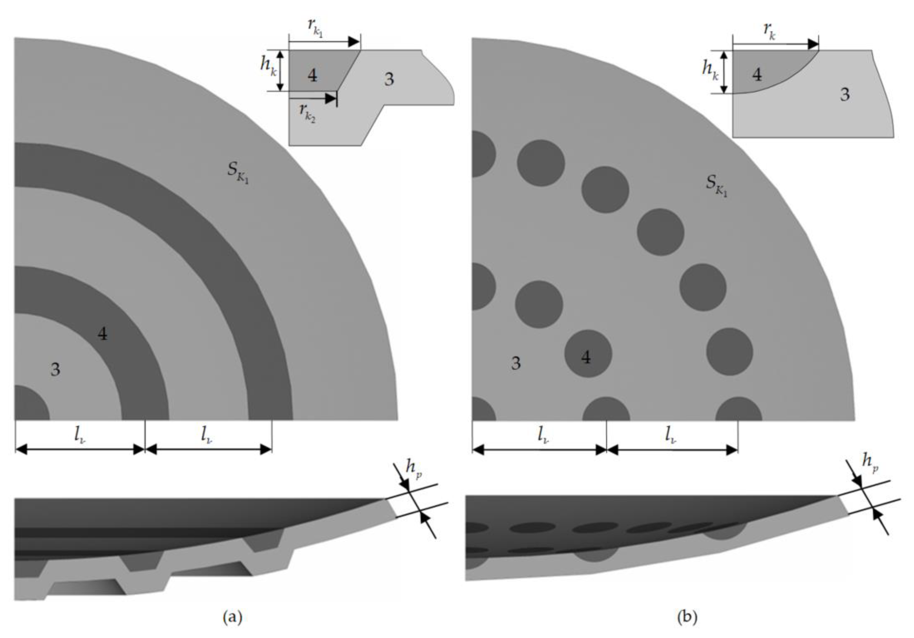
In this study, a mathematical simulation of the parameterized three-dimensional contact junctions in the spherical bridge bearings with different geometries of lubricant recesses was executed, including annular grooves and spherical holes (Figure 2). The numerical investigation consisted of three stages:
  • A comparison of the contact deformation of the bearings with different geometric configurations of lubricant recesses (the annular grooves and spherical holes) using the same arrangement and number of rows of recesses in the polymer sliding layer (three rows of recesses).
  • An analysis of the influence of the arrangement of the lubricant recesses on the deformation behaviour of the structure using the example of a spherical well with a constant number of three rows of recesses.
  • An analysis of the influence of the arrangement of filling the anti-friction layer with lubricant recesses (a change in the number of recess rows) on the nature of the deformation of the bearing as a whole and the parameters of the contact areas in particular.
The anti-friction layer was composed of gamma-irradiated modified PTFE [6] with an h p = 4 mm thickness. The standard geometry of the anti-friction layer comprised three rows of annular grooves with a row spacing of l k = 22 mm. In the first phase of the study, the recesses in the form of spherical holes had the same number of rows and arrangement as the annular grooves. Figure 2 shows the arrangement of filling the sliding layer with lubrication recesses at l k = 22 mm.
The geometric characteristics of the annular groove were as follows: a maximum depth of h k = 3 mm, upper radii of r k 1 5.9 and 3.95 mm, and lower radii of r k 2 4.2 and 2.2 mm for the central and non-central recesses, respectively. The geometric characteristics of the spherical hole were: h k = 2 mm as the maximum depth and r k = 4 mm as the radius.
The lubricant recesses in the sliding layer of the bearing in the form of annular grooves resulted in a more complex geometrical configuration of the spherical cut-out for the anti-friction layer in the bottom steel plate. In the case of the lubrication recesses in the form of spherical holes, the sliding surfaces S K 1 S K 2 remained spherical, which greatly simplified the manufacturing process. In the case of the designs with spherical lubrication recesses, a reduction in the lubricant volume of approx. 48.4% in the standard arrangement of the rows V lubricant holes < V lubricant grooves was observed.
In the second stage of the study, the influence of the well-row spacing on the stress-strain state of the structure when the number of rows was constant (the three rows), l k , ranging from 12 to 28 mm, was investigated. The third stage of the study considered filling the spherical sliding layer with as many rows of holes as possible, with the restriction that the last row of holes could not be closer to the end-face of the anti-friction layer than 4 mm. The last two stages allowed us to evaluate the contact parameters and the deformation behaviors of the sliding layer with different fillings of the interlayer with recesses for the lubricant. This allowed for not only increasing the lubricant volume but also to problem solve the lack of lubrication during the frictional interaction of the elements with the bearing steel plates. The arrangement of filling the anti-friction layer with lubricant recesses in the form of spherical holes is shown in Table 1.
The maximum filling of the spherical sliding layer with lubricant recesses is observed at l k = 12 mm and amounts to 5 rows, approximately 26% in this filling arrangement V lubricant holes < V lubricant grooves .

2.2. Scheme of the Computational Experiments

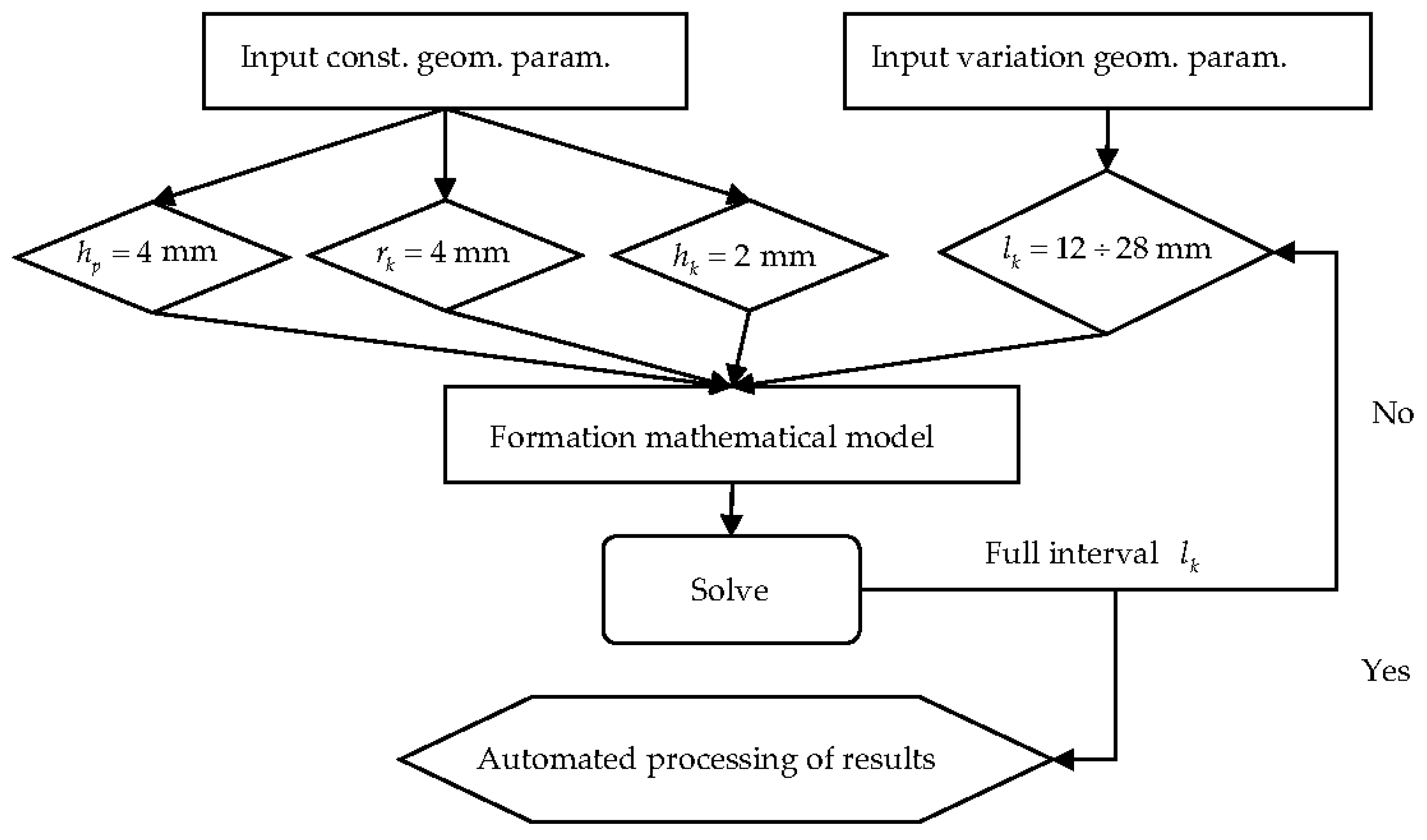
The automation of the process of modeling the lubricant recesses in the form of spherical holes within an iterative procedure and the automation of the processing of the research results was implemented (Figure 3).
The iterative procedure made it possible to cut out and fill the recesses with lubricant where the following geometrical parameters were specified as input parameters: layer thickness, distance between the rows of lubricant, minimum distance between the recesses in a row, recess depth, recess radius, and type of recess.
Numerical experiments were performed on a Soc-1366 SuperMicro 4U 7046T-H6R (Super Micro Computer Inc., San Jose, CA, USA) server platform with two six-core Soc-1366 Intel Xeon X5650 processors and 60 GB of RAM. The implementation time per computational experiment was approximately 2–3 h.

2.3. Materials

In the first approximation, the lubricant was modeled as a low compressive modulus material with an elastic modulus of 2 GPa and a Poisson’s ratio of 0.49999. The steel-lubricant friction coefficient was constant and equaled 0.01, which corresponded to the maximum value of the reference coefficient of friction for solid and paste lubricants [38].
The behaviour of the modified PTFE was described in terms of the deformation theory of plasticity [37]. The properties of the elastic part of the material deformation curve were as follows: a free compression modulus of 863.8 MPa, a constrained compression modulus of 4235.6 MPa, a Poisson’s ratio of 0.461, a steel-polymer coefficient of friction of 0.04 (the reference value). The physical and mechanical properties of the sliding layer material were obtained experimentally at IMSS, UB RAS (Russia, Perm) from Dr. Sci. in Physics and Mathematics, Adamov A.A., in cooperation with “AlfaTech” Ltd.

2.4. Finite Element Model and Contact Elements

A finite element grid was constructed according to previous research on the effect of the degree of discretization of the system on the numerical solution of the problem [39]. During the implementation of the problem, rectangular four-node elements with Lagrangian approximations (PLANE182, ANSYS Mechanical APDL) were used, and the aspect ratio was close to 1:1. A contact pair of CONTA173 and TARGE170 elements was used to realize the frictional interactions of the steel structural elements with the sliding layer. The anti-friction layer was discretized into 8 elements in thickness, and the element dimension was 0.5 mm. A grid with a gradient increase of the element from the contact areas to the surfaces was used to discretize the top and bottom plates S 1 S 2 . The results obtained with the finite element method were verified by the settlement of the bearing with the annular grooves for lubrication. The error of the results calculated from the in situ experiments did not exceed 8%.
Results
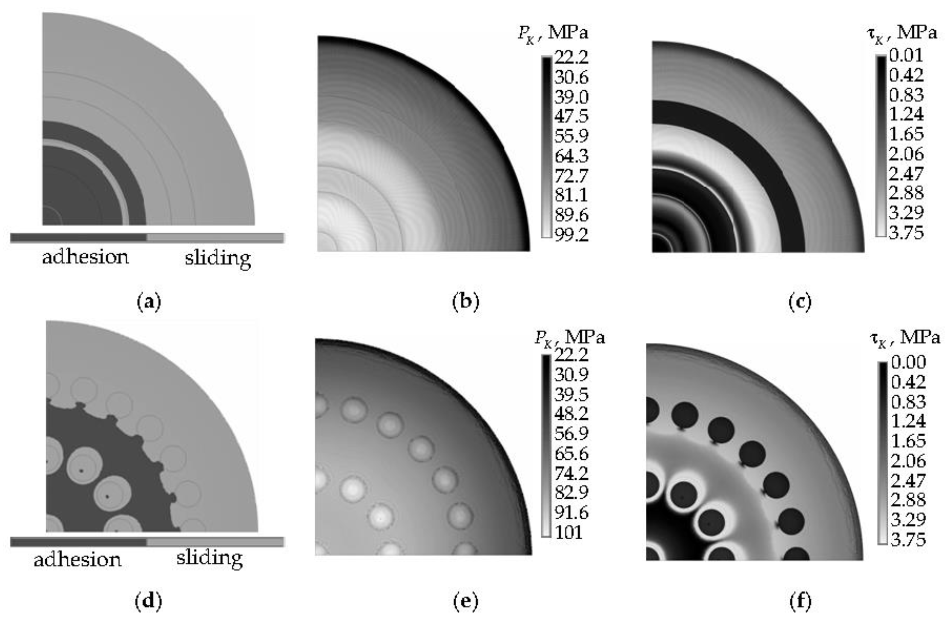
It was pointed out in [21] that an important indicator of the serviceability of the bearing structure is the nature of the distribution and the level of the contact parameters on the sliding surfaces. Figure 4 shows a comparison of the distribution of contact parameters on the surface S K 1 where the lubricant recesses of different configurations are located, and a spherical segment could be rotated at l k = 22 mm.
The pattern of the contact status distribution of the structures with different geometries of lubricant recesses had several features, including areas of full adhesion of contact surfaces observed in the central part of the sliding surface S K 1 and sliding was observed in steel-lubricant contact areas with recess geometries in the form of spherical holes and near holes. In the steel-lubricant contact areas with recess geometries in the form of annular grooves in one and two grooves from the centre of the bearing part on most of the surface, full adhesion was observed. The percentage of the adhesion area was ~22 and 33% in the annular groove and spherical lubricant recess structures, respectively. In the areas of full adhesion, a hydrostatic compression condition was observed, i.e., the material acted as an elastic material.
The distribution patterns of P K and τ K on the contact surfaces of the anti-friction layer with the spherical lubricant recesses were more uniform. The maximum level of contact pressure in the structure with annular lubricant recesses was 0.81% lower than for the second variant of the bearing geometry. The max P K was observed in most of the contact adhesion area of the bearing part surface with annular grooves; only in the steel-lubricant interface areas of the structure with recesses in the form of spherical holes. The percentage of area S K 1 with the max P K was smaller in the bearing with the lubrication recesses in the form of spherical holes. The mean level of the Δ P K was 10.18 MPa and 2.62 MPa higher in the bearing with the annular lubrication grooves in the adhesion and sliding areas, respectively. The max τ K was observed on a larger percentage of the contact area in the structure with the annular lubrication grooves, while the level of max τ K in the structures was the same. The minimum level of τ K was observed in the area of full adhesion of the contact surfaces and the steel-lubricant interface areas in all the structural variants considered.
The maximum intensity of the plastic deformation in the layer was near the end-face of the sliding layer in all structural variants considered and near the lubricant recesses in the bearing with annular grooves. A plastic strain rate greater than 1% was found in approximately 7.51% and 5.19% of the entire sliding layer in the bearings with annular grooves and spherical lubricant recesses, respectively. The maximum plastic strain rate in the layer max ε int P , the displacements along the normal face of the sliding layer max u n , and the settlement u z of the bearings with different configurations are shown in Table 2.
A comparative analysis of the stress-strain state and contact parameters of the layer shows that a layer with spherical lubricant recesses has several advantages. It was necessary to conduct an additional study on the influence of the number of rows of recesses and the distance between them.
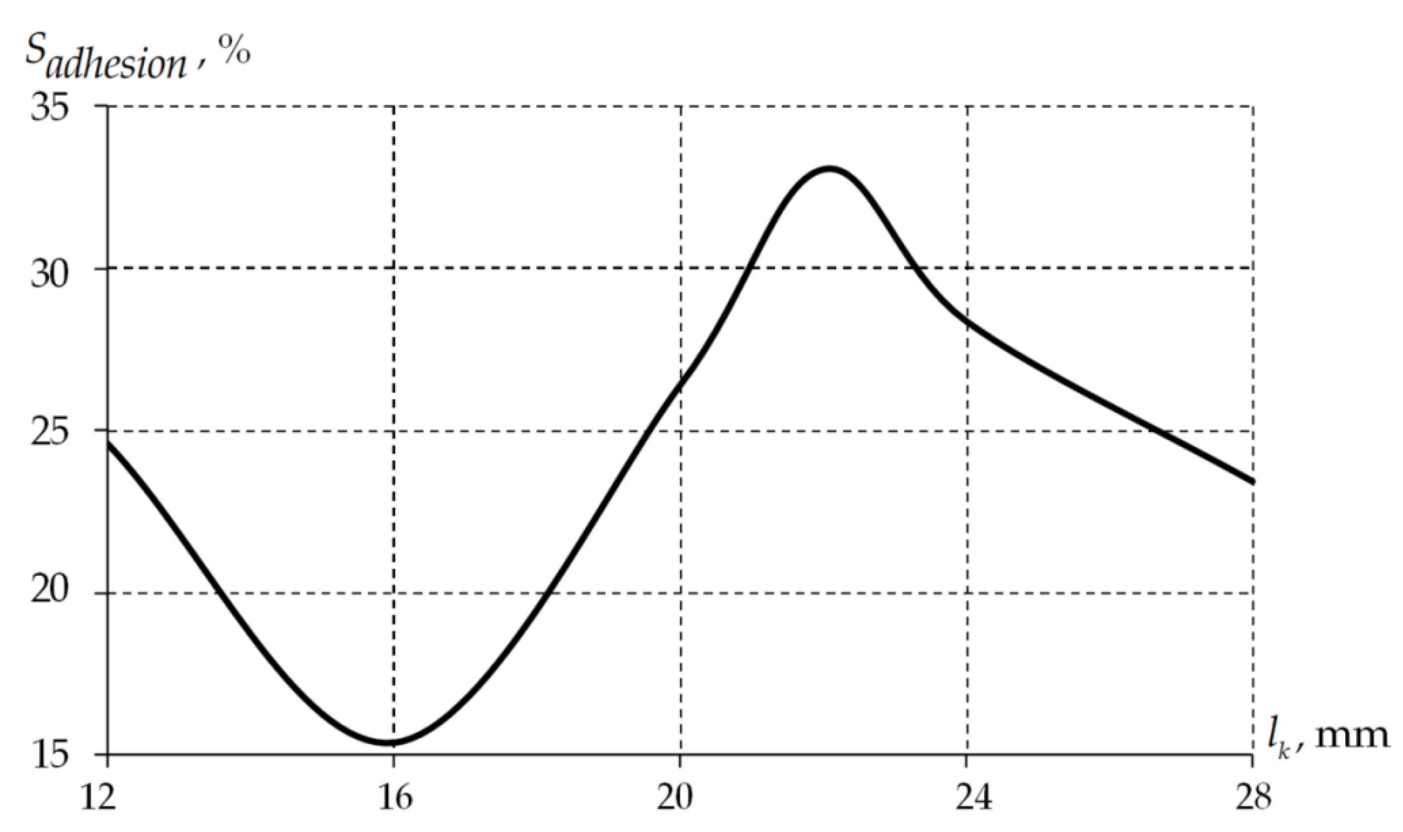
In the second step, the influence of the distance between the rows of recesses in the form of spherical holes at a constant number of rows (three) was assessed. Figure 5 shows the percentage area of full adhesion of the contact surface S K 1 as a function of l k .
The percentage of the full adhesion area ( S a d h e s i o n ) of the contact surface S K 1 does not depend linearly on the distance between the rows of recesses in the form of spherical holes. The minimum value S a d h e s i o n was observed when the distance between the rows of the holes was 16 mm and reached 15.42% and the maximum value at 22 mm was 33.02%. The higher the percentage of the contact surface area in a state of full adhesion, the more the sliding layer material works in terms of elasticity theory. In this case, in the area of full adhesion and near the boundary of the contact state change from adhesion to sliding, the maximum contact pressure was observed. The max P K and max τ K of the areas of full adhesion and sliding of the contact surfaces had minor differences (<0.5%).
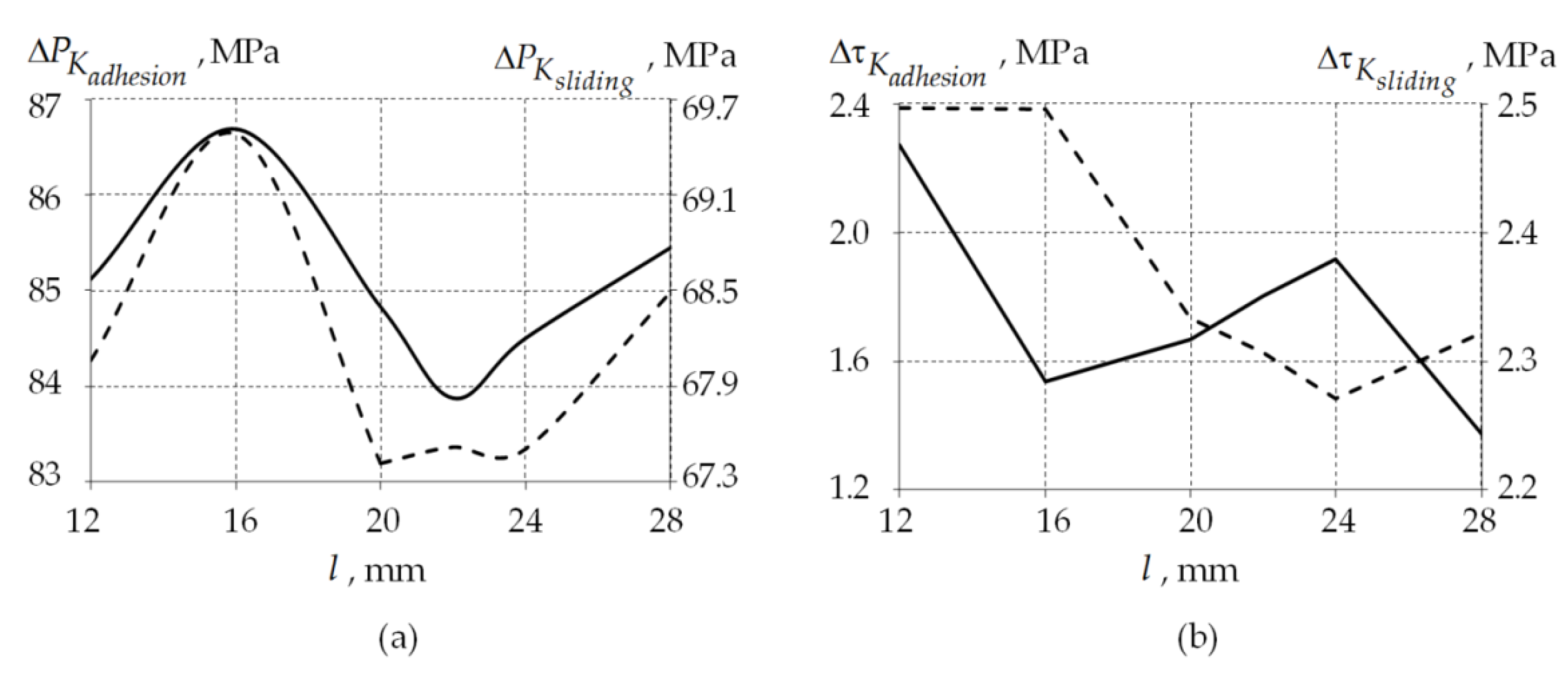
Figure 6 shows the dependencies of the average contact pressure and contact tangential stress level in the areas of adhesion and sliding on the distance between the rows of the lubricant recesses.
The influence of the arrangement of rows of the lubricant recesses in the form of spherical holes on the mean values of the contact parameters was insignificant. The scatter range was 2.07, and the contact pressure was 2.81 MPa. The contact tangential pressure in the sliding and adhesion areas of the contact surfaces were 0.25 and 0.9 Mpa, respectively. The difference of the average values of the contact parameters of the sliding and adhesion areas of the contact surface S K 1 averaged ~17 and 0.61 MPa for Δ P K and Δ τ K , respectively.
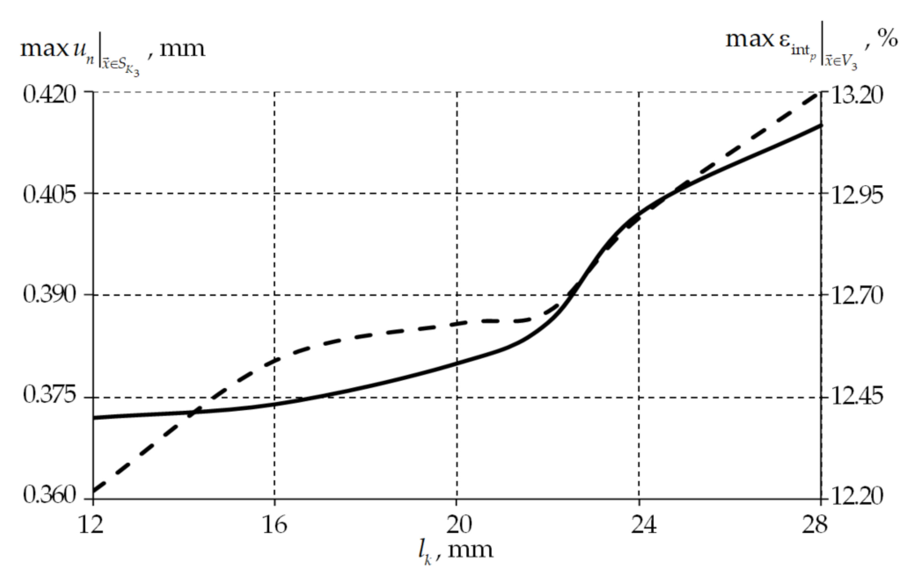
Figure 7 shows the dependences of the maximum normal displacement relative to the free face of the contact surface S K 3 and the maximum level of plastic strain rate in the volume of the sliding anti-friction layer material V 3 .
An increase of max u n in the distance between the rows of holes was observed due to the influence of the last (third) row of holes on the deformation near the edge of the anti-friction sliding layer max u n ( max u n | l k = 28 mm > max u n | l k = 12 mm   by 11.56%, which was 0.043 mm). Since the maximum plastic strain rate in the layer was observed near the contact surface S K 3 (the sliding layer edge), it increased the distance between the rows of holes influencing max ε int P ( max ε int P | l k = 28 mm > max ε int P | l k = 12 mm by 1%). The settlement of bearings u z was independent of the arrangement of the rows of lubricant recesses in the form of spherical holes and was 0.109 mm.
The next stage of the research was to simulate how the maximum possible number of rows of lubricant recesses could fill the contact surface S K 1 . The results of the study on the integral characteristics of the contact area are shown in comparison with an arrangement of filling the sliding layer with three rows of lubricant recesses and a bearing with annular grooves (Table 3). In the table, filling arrangement one is three rows of recesses, and filling arrangement two is the complete filling of the sliding layer with the lubricant recesses.
The model of the bearing with lubricant recesses in the form of spherical holes (for all the variants of the anti-friction layer filling arrangements considered) had several features that differed from the structure with the annular lubricant grooves:
-
The average contact pressure in the full adhesion areas of the contact surface was 7.3% lower on average;
-
The average contact tangential stress in the full adhesion areas of the contact surface was higher by 0.3–1.8 MPa;
-
A more uniform distribution of contact parameters across the sliding surface.
In the second arrangement of filling the lubricant recesses on the sliding surface, there was a significant reduction in the percentage of the contact area in the full adhesion state due to an increase in the number of lubricant recesses in the central area of the sliding layer. This effect is particularly noticeable with a row spacing of 12 mm. At l k = 12 mm and full filling of the sliding layer with lubricant recesses, there is a minimum difference between the mean values P K and τ K in the adhesion and creep areas, with the highest level of P K and τ K being the lowest among all the variants of the bridge bearing configurations considered. A plastic strain rate of more than 1% was observed in 5.68% of the sliding layer material volume, and the max ε int P was a maximum of 12.15%. The maximum displacements along the normal sliding surface S K 3 reached 0.398 mm.

3. Discussion

3.1. Limitation Statement

The influence of a mathematical model of lubricant and anti-friction material has been investigated as one of the stages in the study of the behaviour of bridge bearings and the materials from which they are made. The research has several limitations:
-
A constant coefficient of friction of 0.04 was taken from the manufacturer’s data on the bridge bearings;
-
A simplified model of the lubricant’s behaviour as a low compressible body without viscoplasticity;
-
The sliding material model is, in the first approximation, elastoplastic;
-
A quarter of the structure was modelled so that the horizontal load of the bridge span could not be introduced into the system;
-
The ambient temperature was constant at 23 °C.
In the future, the researchers will have some tasks to perform:
-
An analysis of the operation of the structure under experimentally obtained friction coefficients [18];
-
A refinement of the mathematical model of lubricant (viscoelasticity) and anti-friction (viscoelasticity) materials;
-
An extension of research to a wide temperature range (−60 °C to +60 °C);
-
The introduction of horizontal and dynamic loads;
-
An analysis of the influence of geometrical features of lubricant pits;
-
The determination of manufacturing requirements for the bridge bearing, in particular, to increase the durability of the bridge span as a whole.

3.2. About the Materials

The active development in manufacturing new materials in various productions is currently taking place. The synthesis effect on the strength and corrosion properties of thin films was studied in [40,41]. The influence studies of various impurities on the electrodynamic parameters, which make it possible to increase the structure’s service life, were carried out in [42,43,44]. Much attention has been paid to the frictional properties of nanocomposite films through work conducted by Darwish et al. [45]. Various modern anti-friction materials are used as bearing sliding layers. The development of modern materials and the comprehension of their operation in structures will make it possible to rationalize the work of bridge structures’ critical elements, such as bearings.
PTFE has been the most widely used material for anti-friction layers of bridge bearings [21]. The improvement of the physical and mechanical properties of the material and its tribology after irradiation has been noted [46,47]. The authors considered the possibility of using modified PTFE as a relatively thin sliding layer of a spherical bridge span bearing. The numerical model of the bearing includes service recesses for the lubricant. In this case, simplified contact geometry is often used in studies of the performance of such structures without considering several structural elements [6,48]. The model of the spherical bearing considered in this work is approximated to the real structure and allows for modeling the nature of its deformation closer to reality. It is of interest to compare the performance of structures with different anti-friction layer materials [6,18]. Also of interest is the study of the performance of different lubricants in the structure and consideration of lubricant viscosity [38,49,50].

3.3. About the Geometric Parameters

The influence of geometric parameters on the deformation behaviors and contact interactions of bearing elements is a relevant task for bridge-building structures. The influence analysis of the interlayer thickness without lubricant recesses is presented in [6]. The minimum deformation of the interlayer at an h p = 8 mm thickness was established. The interlayer geometric arrangement in the spherical bearing of bridge structures plays an important role in the contact parameter distribution and the deformation behavior of the sliding layer [51]. The relevant task is to analyze the geometric parameters of structural elements, such as bearings. Its solution will increase the durability of bridge structures as a whole.
An important result of this work is the regularity of influence of the form and position of the lubricant recesses on the operation of the structure. The analysis of the effects of different lubricant materials and grades on the serviceability of the structure is planned for future research.
A further direction of research is to investigate the stress-strain behaviour of bridge-bearing structures when the sliding layer is filled with lubricant recesses as much as possible with a row spacing of 12 to 16 mm and a 0.5 mm pitch. The model also considers the viscosity of the polymer material and lubricant, the experimentally obtained frictional properties of the steel-polymer material pair, and the analysis of the sliding layer material influence on the structure deformation at different configurations of lubricant recesses and arrangements of filling the sliding layer with them.

4. Conclusions

The bearings with lubricant recesses in the form of spherical holes are found to have a number of advantages:
-
A more uniform distribution of contact parameters across the sliding surface;
-
Plastic strain rates in the layer max ε int P , displacements along the normal to the sliding layer face max u n , and settlements of the bearing u z lower than in the structure with annular grooves for lubrication;
-
A simplified manufacturing process for the bottom steel plate due to the lack of additional cut-outs for the layer with annular grooves.
The study found that the most favourable characteristics of the deformation behaviour were found in the structure with the maximum number of lubrication rows (5 rows) at a row spacing of 12 mm.

Author Contributions

Conceptualization, A.A.K. and Y.O.N.; methodology, A.A.K.; software, A.A.K. and Y.O.N.; validation, A.A.K.; writing—original draft preparation, A.A.K. and Y.O.N.; writing—review and editing, A.A.K. and Y.O.N.; visualization, A.A.K. and Y.O.N.; funding acquisition, A.A.K. All authors have read and agreed to the published version of the manuscript.

Funding

The study was supported by a grant from the Russian Science Foundation (project No. 22-29-01313).

Data Availability Statement

Not applicable.

Acknowledgments

Not applicable.

Conflicts of Interest

The authors declare no conflict of interest.

Nomenclature

S 1 , S 2 boundary condition surfaces;
S K 1 S K 3 contact surfaces;
h p thickness anti-friction layer;
l k row spacing;
h k maximum depth;
r k 1 upper radius;
r k 2 lower radius;
r k radius spherical hole;
V lubricant holes volume of lubrication from the spherical holes;
V lubricant grooves volume of lubrication from the grooves;
P K contact pressure;
τ K contact friction stress;
ε int P plastic strain;
u n normal displacements to the end-face of the sliding layer;
u z sliding layer compresses;
S a d h e s i o n adhesion area;
Δ P K a d h e s i o n average contact pressure in the adhesion area;
Δ P K s l i d i n g average contact pressure in the sliding area;
Δ τ K a d h e s i o n average contact friction stress in the adhesion area;
Δ τ K s l i d i n g average contact friction stress in the sliding area.

References

  1. Shapovalov, V.V.; Sladkovsky, A.; Erkenov, A.C. Actual problems of modern tribotechnology and ways of solution. Bull. High. Educ. Establ. Mech. Eng. 2015, 658, 64–75. [Google Scholar] [CrossRef]
  2. Shapovalov, V.V.; Ryabysh, D.A.; Areshjan, G.A. Technology for monitoring current states of mechanical systems. Vestn. RGUPS 2021, 82, 67–74. [Google Scholar] [CrossRef]
  3. Ren, Y.; Zhang, L.; Xie, G.; Li, Z.; Chen, H.; Gong, H.; Xu, W.; Guo, D.; Luo, J. A review on tribology of polymer composite coatings. Friction 2021, 9, 429–470. [Google Scholar] [CrossRef]
  4. Deng, H.; Zhu, P.; Hu, C.; He, T. Study on dynamic lubrication characteristics of the external return spherical bearing pair under full working conditions. Machines 2022, 10, 107. [Google Scholar] [CrossRef]
  5. Boldyrev, Y.Y. A radial two-sector gas bearing with maximum load capacity. Math. Model. Comput. Simul. 2020, 12, 510–518. [Google Scholar] [CrossRef]
  6. Adamov, A.A.; Kamenskikh, A.A.; Pankova, A.P. Influence analysis of the antifriction layer materials and thickness on the contact interaction of spherical bearings elements. Lubricants 2022, 10, 30. [Google Scholar] [CrossRef]
  7. Fetisov, A.S.; Babin, A.Y.; Tyurin, V.O. Experimental stand for research of journal bearing lubricated by magnetoreological liquid. Lect. Notes Mech. Eng. 2020, 1, 1263–1270. [Google Scholar] [CrossRef]
  8. Cheng, Z.; Huang, K.; Xiong, Y.; Sang, M. Dynamic analysis of a high-contact-ratio spur gear system with localized spalling and experimental validation. Machines 2022, 10, 154. [Google Scholar] [CrossRef]
  9. Timofeev, G.A.; Tsukanov, O.N. Analysis of contact stresses in cylindric-bevel gears at the synthesis stage in generalizing parameters. Vestn. Mashinostroeniya 2020, 4, 41–47. [Google Scholar] [CrossRef]
  10. Velicu, R.G.; Lates, M.T.; Gavrila, C.C. Frictional losses of polyamides mounted on tensioning guides in contact with chains. Materials 2020, 15, 1345. [Google Scholar] [CrossRef]
  11. Manzhirov, A.V.; Kazakov, K.E. Modeling of the contact interaction between a nonuniform foundation and rough punch. Math. Model. Comput. Simul. 2018, 10, 314–321. [Google Scholar] [CrossRef]
  12. Meshcheryakova, A.R.; Goryacheva, I.G. Stress state of elastic bodies with an intermediate layer in rolling contact with slip. Phys. 2021, 24, 441–450. [Google Scholar] [CrossRef]
  13. Arutyunyan, A.M.; Fedotenkov, G.V. Transient contact interaction of a rigid die and elastic half-space with a cavity. Probl. Strength Plast. 2021, 83, 87–100. [Google Scholar] [CrossRef]
  14. Pérez-Ràfols, F.; Nicola, L. Incipient sliding of adhesive contacts. Friction 2022, 10, 963–976. [Google Scholar] [CrossRef]
  15. Myshkin, N.K.; Goryacheva, I.G.; Grigoriev, A.Y.; Kavaliova, I.N.; Makhovskaya, Y.Y. Contact interaction in precision tribosystems. J. Frict. Wear 2020, 41, 191–197. [Google Scholar] [CrossRef]
  16. Decrozant-Triquenaux, J.; Pelcastre, L.; Prakash, B.; Hardell, J. Influence of lubrication, tool steel composition, and topography on the high temperature tribological behaviour of aluminium. Friction 2021, 9, 155–168. [Google Scholar] [CrossRef]
  17. Dastani, H.; Botto, D.; Glorioso, M. Experimental and numerical investigation of contact parameters in a dovetail type of blade root joints. Appl. Sci. 2021, 11, 12008. [Google Scholar] [CrossRef]
  18. Adamov, A.A.; Kamenskih, A.A.; Pankova, A.P. Numerical analysis of the spherical bearing geometric configuration with antifriction layer made of different materials. PNRPU Mech. Bull. 2020, 4, 15–26. [Google Scholar] [CrossRef]
  19. Bourago, N.G.; Kukudzhanov, V.A. Review of contact algorithms. Mech. Solids 2005, 40, 35–71. [Google Scholar]
  20. Burago, N.G.; Nikitin, I.S.; Nikitin, A.D. Algorithms for calculating contact problems in the solid dynamics. Smart Innov. Syst. Technol. 2020, 173, 185–198. [Google Scholar] [CrossRef]
  21. Niemierko, A. Modern bridge bearings and expansion joints for road bridges. Transp. Res. Procedia 2016, 14, 4040–4049. [Google Scholar] [CrossRef]
  22. Rajczyk, J.; Rajczyk, M.; Lazarev, Y.; Rajczyk, P.; Kirillova, D. Elastomer bearing modification for efficient design. Lect. Notes Civ. Eng. 2020, 70, 715–726. [Google Scholar] [CrossRef]
  23. Liu, T.; Yu, O.; Fan, J.; Peng, Z.; Wang, E. Concrete spherical joint contact stress distribution and overturning moment of swing bridge. Structures 2020, 28, 1187–1195. [Google Scholar] [CrossRef]
  24. Guo, J.; Geng, T.; Yan, H.; Du, L.; Zhang, Z.; Sun, C. Implementation of a load sensitizing bridge spherical bearing based on low-coherent fiber-optic sensors combined with neural network algorithms. Sensors 2021, 21, 37. [Google Scholar] [CrossRef] [PubMed]
  25. Xu, T.; Han, G.; Qi, X.; Du, J.; Lin, C.; Shu, L. A Hybrid Machine Learning Model for Demand Prediction of Edge-Computing-Based Bike-Sharing System Using Internet of Things. IEEE Internet Things J. 2020, 7, 7345–7356. [Google Scholar] [CrossRef]
  26. Chong, H.F.; Ng, D.W.K. Development of IoT device for traffic management system. In Proceedings of the 14th IEEE Student Conference on Research and Development: Advancing Technology for Humanity (SCOReD), Kuala Lumpur, Malaysia, 13–14 December 2016. [Google Scholar] [CrossRef]
  27. Karasev, O.I.; Krivtsova, A.O. Assessment of the level of metropolitan cities transport system development. Stat. Econ. 2019, 16, 22–31. [Google Scholar] [CrossRef] [Green Version]
  28. Abdallah, A.M.; Atadero, R.A.; Ozbek, M.E. A state-of-the-art review of bridge inspection planning: Current situation and future needs. J. Bridge Eng. 2022, 27, e0001812. [Google Scholar] [CrossRef]
  29. Sangiorgio, V.; Nettis, A.; Uva, G.; Pellegrino, F.; Varum, H.; Adam, J.M. Analytical fault tree and diagnostic aids for the preservation of historical steel truss bridges. Eng. Fail. Anal. 2022, 133, 105996. [Google Scholar] [CrossRef]
  30. Sengsri, P.; Kaewunruen, S. Additive manufacturing meta-functional composites for engineered bridge bearings: A review. Constr. Build. Mater. 2020, 262, 120535. [Google Scholar] [CrossRef]
  31. Sahu, A.R.; Behera, S.; Mukharjee, B.B.; Mondal, S. Parametric study on dynamic responses of stiffened sandwich composite bridge deck panel. J. Eng. Appl. Sci. 2022, 69, 30. [Google Scholar] [CrossRef]
  32. Schuler, H.; Muller, M. Fatigue measurements in an existing highway concrete bridge. Sensors 2022, 22, 2868. [Google Scholar] [CrossRef] [PubMed]
  33. Contiu, M.; Chiocel, D.M.; Cretu, D.; Botis, M.F. A Step-by-Step Probabilistic Seismic Soil–Structure Interaction Analysis with Ground Motion Incoherency for a Bridge Pier on Bored Pile Foundations. Appl. Sci. 2022, 12, 1828. [Google Scholar] [CrossRef]
  34. Schapery, R.A. Elastomeric Bearing Sizing Analysis Part 1: Spherical Bearing. Int. J. Solids Struct. 2018, 152–153, 118–139. [Google Scholar] [CrossRef]
  35. Heggade, V.N. Bearings & Their Configurations Within Bridge System. Bridge Struct. Eng. 2013, 43, 23–35. [Google Scholar]
  36. Adamov, A.A.; Kamenskikh, A.A.; Strukova, V.I. Influence of geometry and configuration of the spherical sliding layer of bridge bearings on the structure working capacity. Comput. Contin. Mech. 2021, 14, 289–299. [Google Scholar] [CrossRef]
  37. Kamenskih, A.A.; Trufanov, N.A. Regularities interaction of elements contact spherical unit with the antifrictional polymeric interlayer. J. Frict. Wear 2015, 36, 170–176. [Google Scholar] [CrossRef]
  38. Kim, J.-H.; Kim, W.S.; Yoo, Y. Friction Properties of Solid Lubricants with Different Multiwalled Carbon Nanotube Contents. Materials 2022, 15, 4054. [Google Scholar] [CrossRef]
  39. Kamenskih, A.A.; Trufanov, N.A. Numerical analysis of the stress state of a spherical contact system with an interlayer of antifriction material. Comput. Contin. Mech. 2013, 6, 54–61. [Google Scholar] [CrossRef] [Green Version]
  40. Kozlovskiy, A.L.; Zdorovets, M.V. Effect of doping of Ce4+/3+ on optical, strength and shielding properties of (0.5−x)TeO2-0.25MoO-0.25Bi2O3-xCeO2 glasses. Mater. Chem. Phys. 2021, 263, 124444. [Google Scholar] [CrossRef]
  41. Kozlovskiy, A.L.; Zdorovets, M.V. Synthesis, structural, strength and corrosion properties of thin films of the type CuX (X = Bi, Mg, Ni). J. Mater. Sci. Mater. Electron. 2019, 30, 11819–11832. [Google Scholar] [CrossRef]
  42. Almessiere, M.A.; Algarou, N.A.; Slimani, Y.; Sadaqat, A.; Baykal, A.; Manikandan, A.; Trukhanov, S.V.; Trukhanov, A.V.; Ercan, I. Investigation of exchange coupling and microwave properties of hard/soft (SrNi0.02Zr0.01Fe11.96O19)/(CoFe2O4)x nanocomposites. Mat. Today Nano 2022, 18, 100186. [Google Scholar] [CrossRef]
  43. Trukhanov, S.; Kostishyn, V.; Panina, L.; Turchenko, V.; Kazakevich, I.; Trukhanova, E.; Natarov, V.; Balagurov, A. Thermal evolution of exchange interactions in lightly doped barium hexaferrites. J. Magn. Magn. Mater. 2017, 426, 554–562. [Google Scholar] [CrossRef]
  44. Zhumatayeva, I.Z.; Kenzhina, I.E.; Kozlovskiy, A.L.; Zdorovets, M.V. The study of the prospects for the use of Li0.15Sr0.85TiO3 ceramics. J. Mater. Sci. Mater. Electron. 2020, 31, 6764–6772. [Google Scholar] [CrossRef]
  45. Darwish, M.A.; Zubar, T.I.; Kanafyev, O.D.; Zhou, D.; Trukhanova, E.L.; Trukhanov, S.V.; Trukhanov, A.V.; Henaish, A.M. Combined Effect of Microstructure, Surface Energy, and Adhesion Force on the Friction of PVA/Ferrite Spinel Nanocomposites. Nanomaterials 2022, 12, 1998. [Google Scholar] [CrossRef] [PubMed]
  46. Balyakin, V.B.; Khatipov, S.A.; Pilla, C.K. Experimental studies of tribotechnical characteristics of radiation-modified polytetrafluoroethylene to use in rotor supports. J. Frict. Wear 2015, 36, 346–349. [Google Scholar] [CrossRef]
  47. Smolyanskii, A.S.; Politova, E.D.; Koshkina, O.A.; Arsentyev, M.A.; Kusch, P.P.; Moskvitin, L.V.; Slesarenko, S.V.; Kiryukhin, D.P.; Trakhtenberg, L.I. Structure of polytetrafluoroethylene modified by the combined action of γ-radiation and high temperatures. Polymers 2021, 13, 3678. [Google Scholar] [CrossRef]
  48. Oyabu, H.; Fujikura, S.; Hai, N.M.; Takeuchi, S.; Nakajima, A. Behavior of bridge superstructure model with double spherical sliding bearing under live load. Lect. Notes Civ. Eng. 2021, 101, 353–539. [Google Scholar] [CrossRef]
  49. Allmaier, H. Increase Service Life for Rail Wheel Bearings—A Review of Grease Lubrication for This Application. Lubricants 2022, 10, 36. [Google Scholar] [CrossRef]
  50. Wang, Y.; Zhang, P.; Lin, J.; Gao, X. Rheological and tribological properties of lithium grease and polyurea grease with different consistencies. Coatings 2022, 12, 527. [Google Scholar] [CrossRef]
  51. Adamov, A.A.; Kamenskikh, A.A.; Pankova, A.P.; Strukova, V.I. Comparative Analysis of the Work of Bridge Spherical Bearing at Different Antifriction Layer Locations. Lubricants 2022, 10, 207. [Google Scholar] [CrossRef]
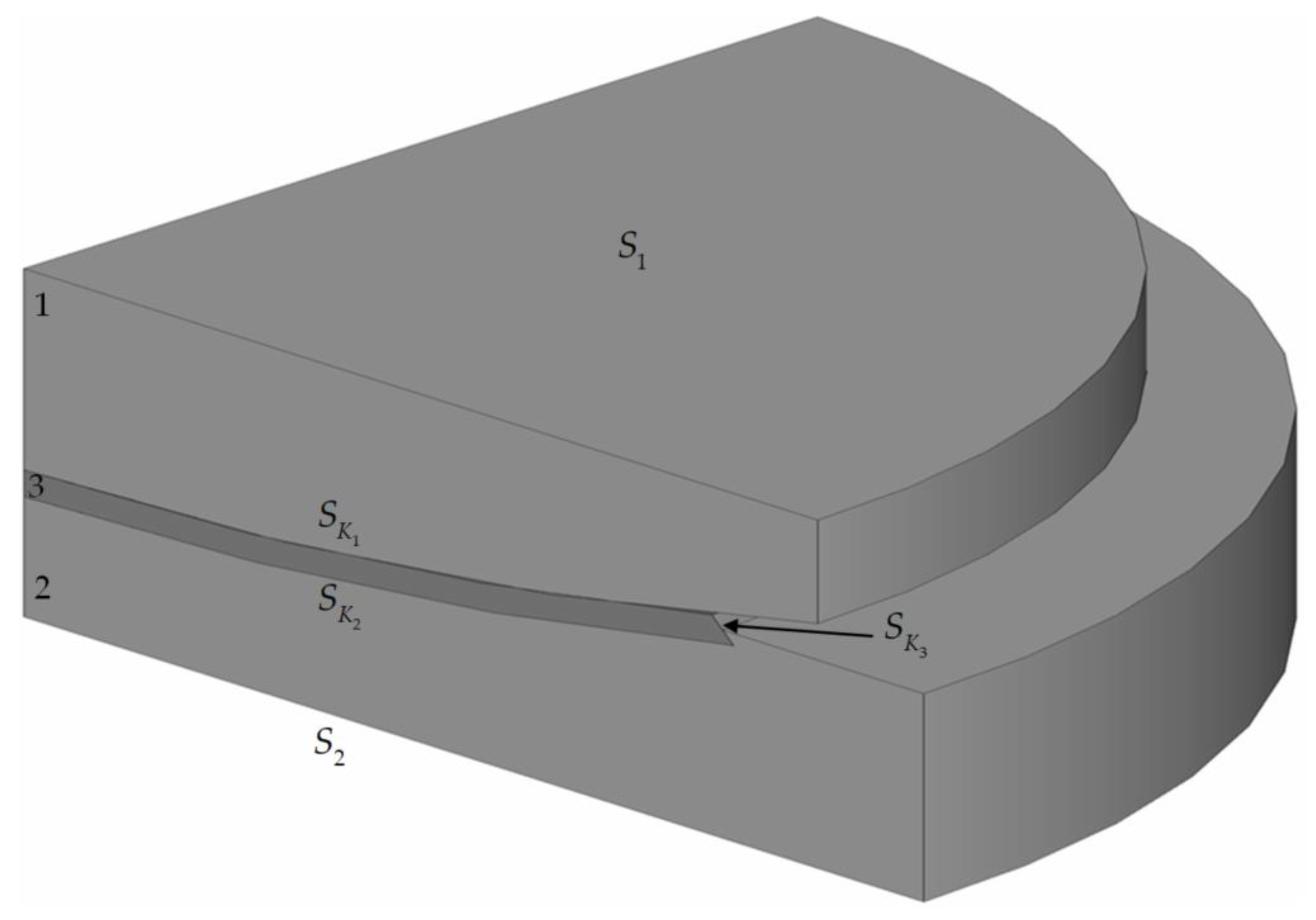
Figure 1. Simplified calculation diagram of the L-100 spherical bearing; 1 is a top steel plate with a spherical segment, 2 is a bottom steel plate with a spherical cut-out, and 3 is a spherical polymer sliding layer; S 1 S 2 are boundary condition surfaces, and S K 1 S K 3 are contact surfaces.
Lubricants 10 00283 g001
Figure 2. Polymer layer (3) with lubricant recesses (4): (a) annular grooves; (b) spherical holes; 3 is interlayer; 4 is lubricant recesses; h k is maximum recess height; r k is spherical hole radius; r k 1 is upper radius of annular groove; r k 2 is lower radius of annular groove; h p is thickness interlayer.
Lubricants 10 00283 g002
Figure 3. Simplified diagram of the computational experiments.
Lubricants 10 00283 g003
Figure 4. The pattern of contact parameter distribution on S K 1 : (ac) are annular grooves, and (df) are spherical holes; (a,d) contact statuses, (b,e) contact pressure, (c,f) and contact tangential stress.
Lubricants 10 00283 g004
Figure 5. Changes in the percent adhesion area of the contact surfaces on S K 1 .
Lubricants 10 00283 g005
Figure 6. Change of Δ P K (a) and Δ τ K (b) to S K 1 : the solid line is adhesion and the dashed line is sliding.
Lubricants 10 00283 g006
Figure 7. The dependence of max u n and max ε int P of the layer on l k : max u n is the solid line and max ε int P is the dashed line.
Lubricants 10 00283 g007
Table 1. The arrangement of filling the layer with lubricant recesses (spherical holes).
Maximum Number of Well Holes l k ,   mm
12162022
(Standard)
2428
3++++++
4+
5+
Table 2. The stress-strain state parameters of the structures.
ParameterBearing Pars with Different Geometries of Lubricant Recesses
Annular GroovesSpherical Holes
max ε int p | x V 3 , %23.1012.66
max u n | x S K 3 , mm0.5550.386
u z , mm0.1300.109
Table 3. The contact interaction parameters on S K 1 .
Parameter l k ,   mm
Spherical HolesAnnular Grooves
Arrangement 1Arrangement 2
121622 (Standard)121622
S a d h e s i o n , %24.5915.4233.0215.6915.6222.07
Δ P K a d h e s i o n , MPa85.1286.6883.8785.6986.0792.41
Δ τ K a d h e s i o n , MPa2.271.541.811.851.491.19
Δ P K s l i d i n g , MPa68.0769.4967.5269.4369.5069.29
Δ τ K s l i d i n g , MPa2.492.492.312.192.292.16
Publisher’s Note: MDPI stays neutral with regard to jurisdictional claims in published maps and institutional affiliations.