Article

Occurrence of Grease Lubricated Impact-Sliding Composite Wear

1
College of Mechanical Engineering, Donghua University, Shanghai 201620, China
2
State Key Laboratory of Solid Lubrication, Lanzhou Institute of Chemical Physics, Chinese Academy of Sciences, Lanzhou 730000, China
*
Author to whom correspondence should be addressed.
Lubricants 2022, 10(11), 284; https://doi.org/10.3390/lubricants10110284
Submission received: 30 September 2022 / Revised: 19 October 2022 / Accepted: 25 October 2022 / Published: 28 October 2022
(This article belongs to the Special Issue State-of-the-Art of Tribology in China)

Abstract

:
In industrial chain drives, the sleeve slides on the pin and impact loading occurs due to the polygon effect, while the collision between the ball and cage usually produces an impact-sliding motion in the rolling element bearings. Aiming at addressing the occurrence of surface damage caused by the impact-sliding motion, a ball–disk test rig employing optical interference technology was designed and built to realize load variation. Two kinds of commercial grease types, Klüber Centoplex 3 and Centoplex 2EP, were used in the experiments when the glass disk slides at a constant speed while the steel ball collides into them. The sliding and impact motions were controlled by PLC programming. After the experiments, the mid-section grease film distributions were measured using DIIM software. The results show that surface damage can rapidly occur even in the first working cycle, and that the phenomenon is affected by the sliding speed, maximum load, and grease consistency. When the sliding speed is low, multiple contacts of asperity peaks occur in the interior contact region and develop into adhesive wear. When the sliding speed increases, surface wear starts to occur at the side-lobe position of the elastohydrodynamic lubrication (EHL) horseshoe shape and extends with time accompanied by obvious surface scratches. The wear mechanism investigated provides valuable visible information for the further exploration of impact-sliding composite wear. It is suggested that great attention should be paid to impact-sliding wear occurring with grease lubrication since such working conditions are very common in industrial applications.

Graphical Abstract

1. Introduction

Fundamental mechanical components such as chain drives, rolling element bearings, gears, etc., are often subjected to alternating loads during the working process, which changes the lubrication state and causes fatigue and reliability problems in severe cases. From the perspective of the presence or absence of tangential velocity, the alternating load problems are categorized into two types: one is the pure squeeze condition without tangential velocities, and the other is the rolling or sliding contact condition with impact load.
The former has been studied extensively and thoroughly from the aspect of oil lubrication based on EHL theory. For example, Kaneta et al. [1] conducted numerical calculations using multi-grid methods to simulate two kinds of pure-squeeze entrapments observed in optical interference experiments. Fryza et al. [2] conducted an experimental study on the concave phenomenon of EHL oil film with different initial impact gaps, approach speeds, loading speeds, and various lubricants, and found that the shape of the concave oil film directly depended on the loading speed. The film thickness mainly depended on the approach speed and lubricant viscosity, where the effect of the impact time/speed was estimated from the basic rheological properties of the lubricant. Wang et al. [3] obtained a formula for the central film’s thickness in the case of a pure impact motion through isothermal numerical research. Wang et al. [4] established a thermal EHL model to solve a lubrication problem wherein a steel ball impacts into a semi-infinite surface in free fall. Wu et al. [5] used numerical methods to solve the effect of oil starvation on isothermal EHL characteristics during pure impact motion.
Some scholars have also studied the pure-squeeze problem from the perspective of wear. The research on the wear problem has been mainly carried out on wear test machines. After the experiment, the wear scars on the surfaces of the two specimens are observed by a scanning electron microscope (SEM) and surface topography apparatus. Wang et al. [6] built a small-load impact load-testing machine and carried out impact wear experiments on the TC4 alloy. Wang et al. [7] studied the effect of oil viscosity on the surface damage of 40Cr specimens under cyclic impact load through a self-made heavy-load-impact-tester. Ji et al. [8] studied the impact of seawater and seawater/oil mixture as lubrication on the impact crater, plastic deformation, and damage of the GCr15 bearing steel through an impact wear test machine. Then, Wang et al. [9] explored the surface damage of GCr15 bearing steel under four grease contact conditions through experiments.
However, in industrial applications, the second type of problem is more common; that is, the effects of both the tangential velocity and alternating load occur between the two working surfaces. In the contact between the pin and sleeve in the roller chain or sleeve chain, due to the polygon effect, impact loading frequently occurs while the sleeve slides in a reciprocating manner with the pin. In high-speed angular contact rolling element bearings, the collision between the ball and cage usually produces an impact-sliding motion between the ball and the cage. For such problems, there are few studies to refer to that concern the use of oil lubrication. For example, Ren et al. [10] numerically simulated the influence of different loading conditions and different stroke lengths on the EHL line contact’s reciprocating motion. Yin et al. [11] used a self-made impact-sliding wear tester to study the effects of the impact kinetic energy and sliding velocity on the energy absorption, mechanical response, interface deformation, and damage behaviors of 304 nuclear grade stainless steel (304SS). Tan et al. [12] studied the applicability of laser shock peening (LSP) to impact-sliding wear under different system stiffnesses through an impact-sliding test device and explored the wear performance of an LSP treatment. Yin et al. [13] studied the effect of ultrasonic surface rolling (USRP) on the impact-sliding wear behavior of Inconel 690 alloy tubes through a self-made cyclic impact-sliding wear test bench and revealed the effect of the USPR treatment on the wear mechanism.
Aiming at the impact-sliding motion that occurs between the sleeve and pin of industrial chains, the following experiments were designed based on the visual research of impact-sliding composite wear using optical interference technology on a self-made ball–disk test rig. Considering the wide range of grease applications, this paper uses two types of commercial grease as lubricants to study the origin and occurrence of impact-sliding composite wear. Another reason for using grease lubrication is that under the same experimental conditions, general PAO synthetic oil was used by the authors and due to the good fluidity of the oil, no surface damage occurred under the same conditions. By using the optical interference technique, the authors hope to clarify the occurrence of impact-sliding wear under grease lubrication conditions.

2. Experimental Equipment and Conditions

2.1. Experimental Equipment and Principle

A ball–disk test rig (schematically shown in Figure 1) was designed and established in order to complete the load-varying EHL experiments using optical interferometric experiments. The test rig consists of a loading system, a motion control system, an image acquisition system, and a mechanical main body. The motor and the screw are connected by a coupling, and the rotation of the servo motor is controlled by PLC programming to realize the process of impact loading. The load change in a load change cycle is shown in Figure 2. The speed change of the glass disk was designed by PLC-programming control [14]. The authors implemented PLC programming to control a servo motor for load variation.
The image acquisition system is mainly composed of five parts: a light source, a microscope, a CCD camera, an image acquisition card, and a computer. In this experiment, a two-color red and green laser light source was used (red wavelength λ = 653 nm; green wavelength λ = 532 nm). The CCD camera is responsible for collecting light interference images amplified by the microscope. The collected signals are analog signals, and 350 frames of images can be collected per second. The image acquisition card is responsible for AD conversion and the capturing of images. A computer is used to control the collection and store the optical interference images through software.

2.2. Experimental Materials and Parameters

The glass disk is made of K9 glass. The lower side of the glass disk that contacts the steel ball is coated with a chromium film with a nominal thickness of 15 nm and a SiO2 underlayer with a nominal thickness of 120 nm, and the surface roughness of the coating corresponds to Ra = 4 nm. The steel ball is made of GCr15 steel with a precision of G5. The parameters of the disk and ball are shown in Table 1.
The experimental grease types used were Klüber Centoplex 3 and Centoplex 2EP. The specific parameters of the grease are shown in Table 2.
During the test, the ambient temperature was set as 24 ± 0.5 °C, and the humidity was 60 ± 5%. The glass disk rotates while the steel ball impacts the glass disk repeatedly. In the test, sufficient grease was used to ensure that the tracks of the glass disk and the steel ball were evenly and adequately greased. The selection of the test speed parameters was based on the research of Han et al. [15]. The superiority of grease lubrication over oil lubrication stems from the ability of grease to form a thick film under a lower entraining speed. The variation in the grease film’s thickness versus the entraining speed shows a V-shape [15]. The bottom point of the V-shape is called the critical speed. Below the bottom point, a very thick grease film thickness is generated, above which the grease film is consistent with the film thickness of basic oil. Three sliding speeds—0.02 m/s, 0.05 m/s, and 0.1 m/s—were selected. It should be pointed out that the results of Han et al. [15] were obtained under pure-rolling conditions, while this experiment was completed under simple sliding-impact conditions, so the selection of the above speed parameters is only for reference.
After the experiments, the film thickness was measured by a dichromatic light interference intensity modulation technique (DIIM), and the film thickness resolution was 1 nm, which was effective for efficiently and accurately measuring the lubricating film thickness in the range of 0~4 μm [16].

3. Results and Discussion

The glass disk rotates, and the steel ball performs a reciprocating impact motion in the vertical direction. The variations in the sliding speed and the impact load are controlled through PLC programming. During each experiment, the sliding speed of the glass disk is kept constant. Under the premise of ensuring that the maximum impact load is constant, different cycle times are obtained by changing the impact speed. While keeping the impact velocity constant, the maximum impact load is increased, and the cycle time is extended accordingly. The experimental parameters are shown in Table 3. In total, seven experiments were carried out.

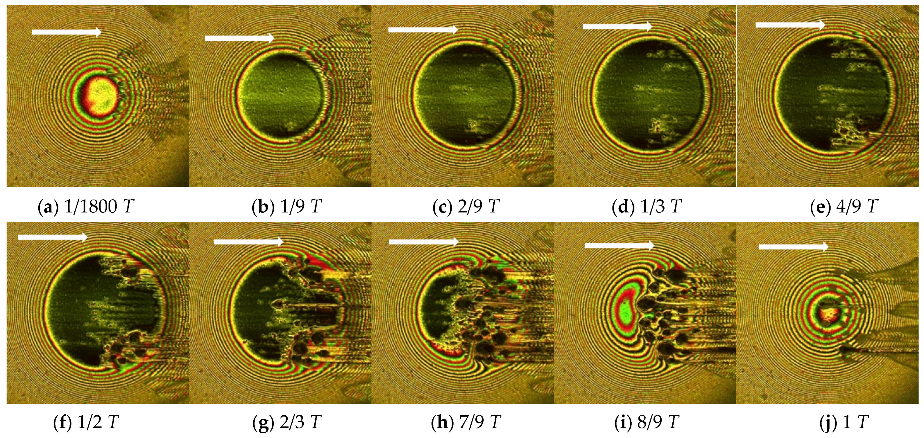
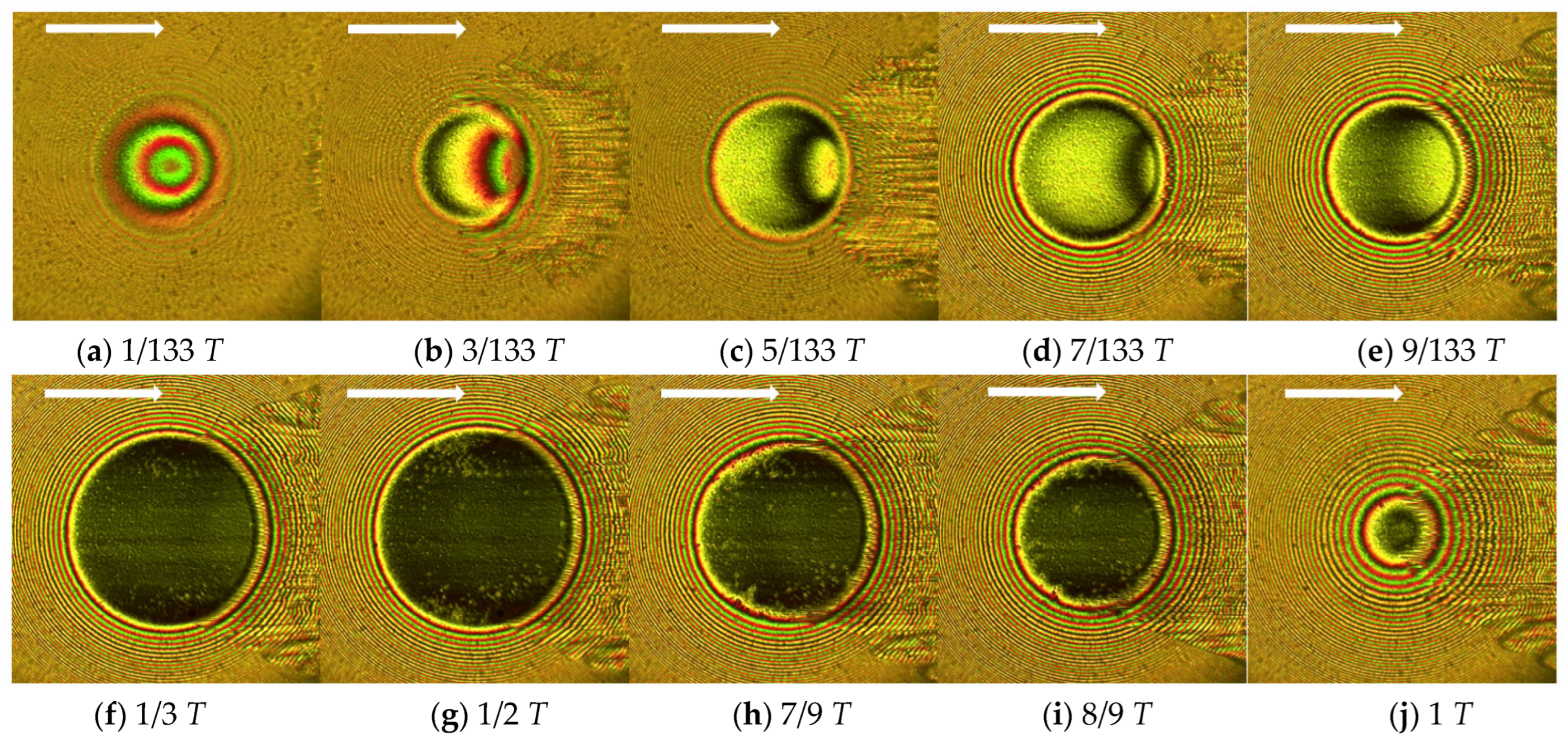
3.1. Centoplex 3 Grease

In order to visually explore the effect of the sliding speed on the occurrence of grease-lubricated wear, Figure 3 shows optical images of the grease film during a single loading–unloading cycle with the grease Centoplex 3 (Experiment No.1 in Table 3). The entraining speed was 0.02 m/s, below the critical speed in the pure rolling condition studied by Han et al. [15]. The maximum impact load was 66 N, generating a maximum Hertz contact pressure of 0.67 GPa. The impact cycle lasted for 6 s. The white arrow in each optical image indicates the entraining direction. Figure 4 shows the mid-section film thickness curves corresponding to the first three optical images in Figure 3. From Figure 3d onwards, multiple direct contacts of asperity peaks in the contact region have occurred and the minimum film thickness has become 0, so it is unnecessary to provide the mid-section film thickness. Figure 3a shows the first image captured by the camera in the loading process. At this time, the two contacting solids have undergone slight elastic deformation, as the horseshoe shape in the contact indicates an EHL state. The central film thickness is about 0.2 μm, while the minimum film thickness at the constriction is 0.1 μm. At the time instant 1/9 T shown in Figure 3b, the contact area is clearly enlarged, and the horseshoe-shaped film has disappeared. The corresponding mid-section film thickness (Figure 4b) in the contact region is thin, only about 25 nm. Several asperity peaks in the middle of the contact area already show evidence of direct contact, but no damage has occurred. In Figure 3c, the contact area is enlarged further while the central film thickness is reduced to 5 nm, and the direct contact points have clearly increased. In Figure 3d, as the load increases, more direct contact points emerge, and all of those points are connected to patches and significant wear occurs inside the contact area. Near the outlet region, the grease at the local contact is depleted. In Figure 3e, the wear situation becomes more severe with the increase in the load. In Figure 3f, the load has reached the summit, so the contact area is again enlarged, and the wear area has expanded to almost the entire contact region. The surface damage is severest in the contact center and obvious surface scratches at the outlet of the contact can clearly be seen. Then, the load starts decreasing. However, surface damage takes place persistently throughout the unloading process, although the contact area is reduced due to the reduced load. In Figure 3g–i, the messy surface damage is observed. At the left inlet area where no surface damage is seen, a local complete grease film has been reproduced. In Figure 3j, the load is zero, but due to the local surface damage, the distribution of the grease film is distorted.
Figure 5 shows the optical interferometric images with a higher sliding speed of 0.05 m/s in the first cycle (Experiment No.2 in Table 3). Due to the same occurrence of local direct contact of the asperity peaks, only five mid-section film thicknesses corresponding to the first five images of Figure 5 are given in Figure 6. The white arrow in each image indicates the entraining direction. Figure 5a shows the first image captured by the camera in the loading process while the time instant is 1/1800 T, different from that in Figure 3a. This is due to the randomness of the camera’s shutter speed. In addition, the other time instants selected are the same as those in Figure 3. In Figure 5a, the horseshoe shape is not obvious. Compared with Figure 3, only the sliding speed increased, as seen in Figure 5b,c; tiny direct contacts occur not only in the contact center, but also at the two sides of the contact. Moreover, the number of direct contact points improve when progressing to the rest of the images. The corresponding mid-section film thicknesses in either Figure 6b or Figure 6c are thicker than those in Figure 4b or Figure 4c, respectively. Obvious surface damage is seen in Figure 5d, and the degree increases in the following loading–unloading process. The wear severity in each image is alleviated compared with that in the corresponding image in Figure 3. In Figure 6f,g, surface damage mainly occurred at the location of the side lobes. In Figure 6h,i, multiple damaged points—shown in black—can be seen in the rear part of the contact and scratches can also be noticed. Since the glass disk was sliding, the wear surface in Figure 6i has moved out of the contact and the load became zero; thus, no black points can be seen in Figure 6j.
Figure 7 shows the optical interferometric images when the sliding speed of the glass disk is 0.1 m/s, while Figure 8 gives the corresponding mid-section film thickness curves along the entraining direction (Experiment No.3 in Table 3). The other conditions remain unchanged. The increase in the sliding speed of the glass disk further increased the film thickness. Surface damage only occurred at the location of the two side lobes of the horseshoe shape of the grease film and the severity also increased along with the loading–unloading cycle. Since no damage occurred along the mid-section of the contact along the entraining direction, the mid-section film thickness profiles for all images are presented. Due to the surface damage at the side lobes, the contact area has been molded into a trumpet shape, as shown in Figure 7g–i.
From the comparison of Figure 3, Figure 5 and Figure 7, it can be seen that under the condition of a low sliding speed, the adhesive wear of the contact area is the most serious. The change in the location of the wear occurrence is due to the increase in the sliding speed of the glass disk. It must be mentioned that in the optical images of Figure 3, Figure 5 and Figure 7, no traces of thickener clusters can be seen. This can be attributed to two causes. Firstly, the minimum speed of 0.02 m/s selected in the study is already the critical speed of Centoplex 3 under pure rolling conditions. Secondly, according to the research conclusions of Han et al. [17], the fiber clusters of the grease thickener in the region decreased significantly with the increase in the slide-to-roll ratio.
Although in the pure rolling condition, which is below the critical speed, a thick grease film can be maintained for a quite long time [15], under an impact-sliding motion, the higher the sliding speed of the glass disk, the better the maintenance of the lubrication state. That is to say, the superiority of film formation in grease lubrication is lost in the first cycle of an impact-sliding motion. Since impact-sliding motions are very common, the significance of this phenomenon is worth heeding.

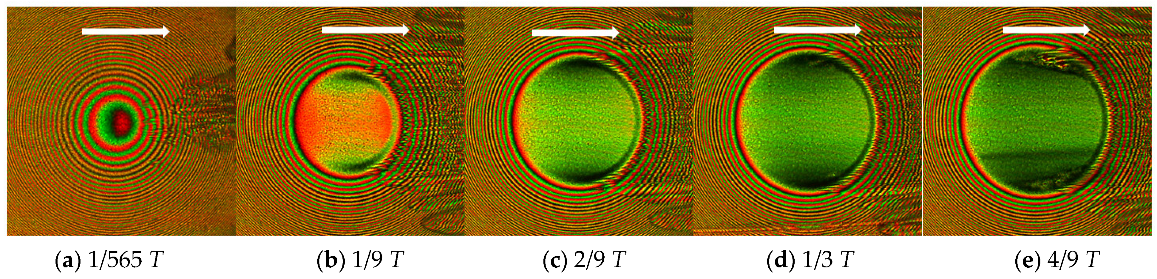
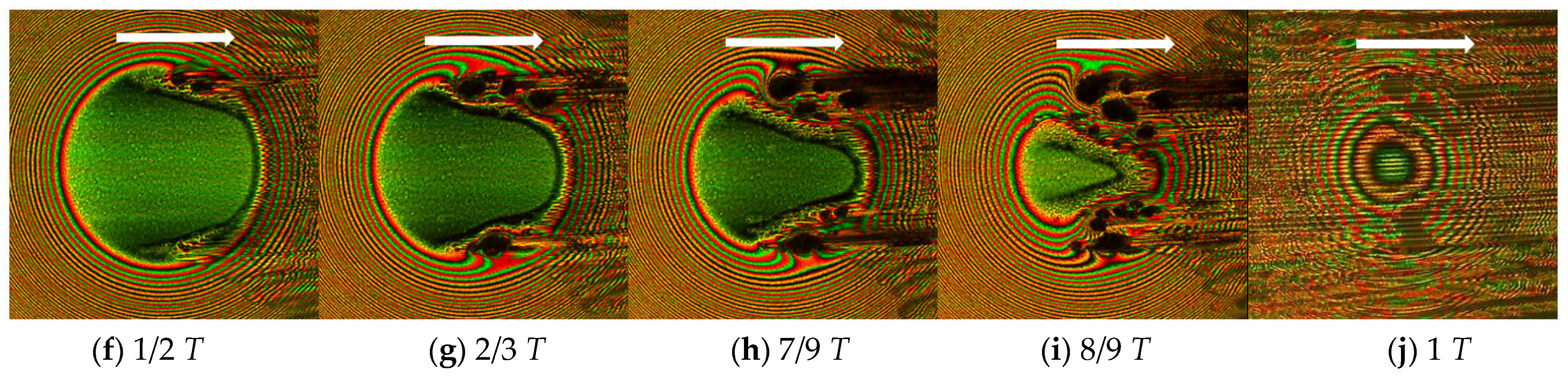
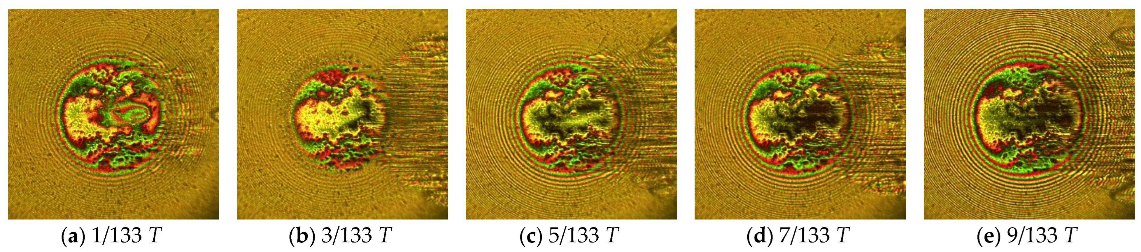
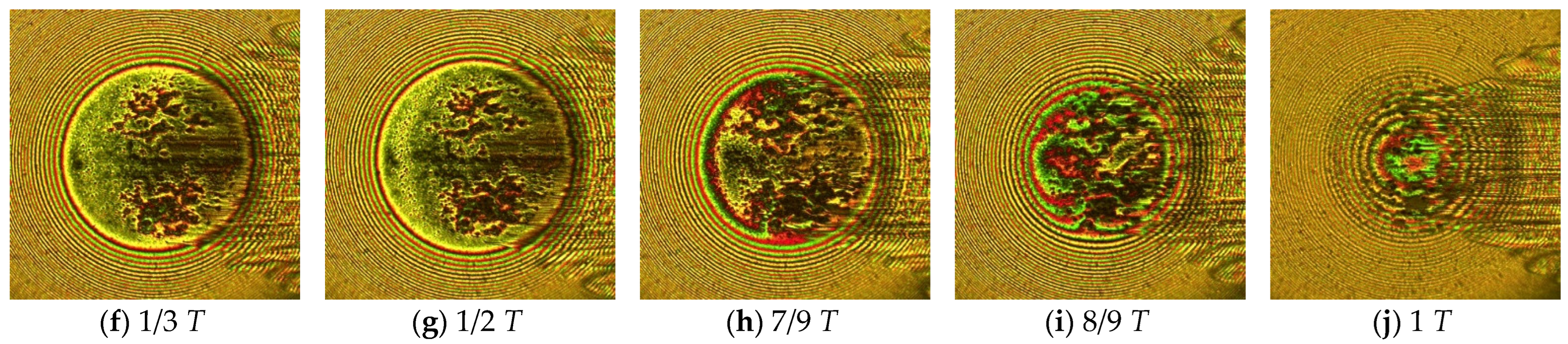
3.2. Centoplex 2EP Grease

In order to study the effect of the grease’s consistency, Figure 9 shows the optical images of the grease film of the first cycle with the grease Centoplex 2EP for vs = 0.05 m/s, wmax = 66 N, and T = 6 s, and three corresponding mid-section film thickness curves are shown in Figure 10 (Experiment No.4 in Table 3). The entraining speed is 0.025 m/s, below the so-called critical speed of Centoplex 2EP studied by Han et al. [15]. Compared to Figure 5, the other conditions remain unchanged. Figure 9a shows the 1/1800 T moment when the contact area is in the EHL state, and there is no cavitation area in the outlet area. After that, the load is increased, and the film thickness is reduced. Multiple direct contacts of asperity peaks emerge soon after the impact motion and develop into a disorderly area in the contact center. This tendency is the same as the results with Centoplex 3. Wear continued to occur in the unloading process. The occurrence of the wear phenomenon is similar to what is shown in Figure 3. Since the viscosity of the base oil of Centoplex 2EP is higher than that of Centoplex 3, and few thickener clusters enter the contact, the reason for the difference likely stems from the NLGI grade. The Centoplex 2EP grease contains EP additives, but the effect of EP additives is not the aim of the study. As far as the authors know, the EP additives in lubricants do play a role but this role is usually limited. From Table 2, the difference in the NLGI grades of the two grease types seems to explain the phenomena in Figure 5 and Figure 9.
Figure 11 shows the optical interferograms in the first cycle when the sliding speed of the glass disk is 0.1 m/s, and Figure 12 displays the first five corresponding mid-section film thickness curves (Experiment No.5 in Table 3). With a higher sliding speed, multiple direct contacts firstly happen at the location of two side lobes, causing obvious surface damage that invades the contact center and causes the disorderly appearance of the majority of the contact circle. The wear pattern in Figure 11 does not resemble what is shown in Figure 7, although the sliding speed is the same. Wear initially occurs at the side lobes of the contact area due to the lower consistency of the Centoplex 2EP grease. The mid-sectional film thickness in Figure 12 is significantly lower than that of Centoplex 3 grease at the same instant. Therefore, fewer contact points and scratches were found in the center of the contact area. During the unloading process, more severe surface damage occurs, so the shape of the contact area becomes similar to that shown in the unloading process of Figure 3. The comparison between Figure 11 and Figure 6 or between Figure 9 and Figure 5 shows that the consistency of the grease significantly affects the occurrence of wear in the contact zone.
In order to study the effect of the working period, Figure 13 shows the optical images of the grease film of the first cycle under the condition of Experiment No. 6. Figure 14 gives the corresponding mid-section film thickness curves. The impact cycle lasts for only 0.48 s. Figure 13a shows the results of the 1/133 T instant when the steel ball and the glass disk have just contacted. Due to the high impact velocity, a grease film entrapment appears in the center of the contact area. At the instant 3/133 T shown in Figure 13b, due to the presence of tangential velocity, the grease entrapment is transported to the right side of the contact area. In Figure 13c, the previous entrapment has almost been moved out of the contact area, only a small patch remains at the right side, and there is a newly formed shallow entrapment at the left side. The new entrapment is also transported to the right side of the contact area, as shown in Figure 13e, and cannot be seen in Figure 13f any longer. The occurrence of the entrapment is due to the obvious transient effect by shorter working period. In Figure 13f, local direct contact occurs on both sides of the contact area. In Figure 13g, since the load reaches the maximum value, the grease film thickness is further reduced compared to Figure 13f, and the number of direct contacts of asperity peaks increases. In Figure 13h, the contact area decreases as the load decreases. In Figure 13i–j, as the load decreases, the contact area is further reduced until it returns to the fluid lubrication state. Figure 14 shows that a short working period is beneficial to a impact-sliding motion.
Figure 15 presents the optical images of Experiment No. 6 but in the fifth working cycle. A smaller impact entrapment is seen in Figure 15a. Obvious surface damage has occurred inside the contact area. Figure 16 gives the results of the 22nd working cycle, in which significant surface damage has occurred, demonstrating that with grease lubrication, an even shorter working period is beneficial but can sustain only tens of cycles.
Figure 17 and Figure 18 show the optical images and some corresponding mid-section film thickness curves with a larger maximum impact load, namely, 95 N. The larger load results in a maximum Hertzian pressure of 0.76 GPa. The impact cycle is 8 s, indicating that the impact velocity is a little higher than that in Figure 11. The times used in Figure 17b–e were selected to be the same as those in Figure 11b–e: 2/3 s, 4/3 s, 2 s, and 8/3 s. In each image of Figure 17b–e, since the actual load is higher, the damage is severer. Compared with Figure 11, the wear is more severe at each moment because of the heavier load. In the unloading process, severer surface damage occurs and at 1 T; the contact is all black. The mid-section film thickness (Figure 18) is also thinner than each corresponding one in Figure 12.
As in all EHL experiments conducted on ball–disk test rigs using the optical interferometric technique, the significance of this work lies in the visualization of the occurrence of surface damage. The central plateau, side lobes, and outlet constriction of an EHL oil film shape were revealed by optical experiments [18,19] but also validated by numerical analyses [20,21]. The famous surface dimple phenomenon was first observed by Kaneta et al. [22,23] and then simulated successfully by Yang et al. [24,25]. The process by which the surface damage originates and develops in the impact-sliding motion using grease lubrication is explored according to different entraining speeds. For metal–metal contacts, experiments that replace a glass disk with a steel disk may lead to a significant difference. As a part of the authors’ research plan, the surface damage in steel–steel contacts will be investigated in the future. Moreover, a mixed EHL mathematical model should be established for further investigation.

3.3. Surface Damage of Steel Ball

Figure 19 shows the optical microscope photos of the worn surface of the steel ball under the condition of using Centoplex 2EP grease for experiment Nos. 3~6 (corresponding to Figure 7, Figure 9, Figure 11, and Figure 16, respectively). It can be seen that obvious adhesive wear and scratches occurred on the ball’s surface. The damage pattern on the surface of the steel ball is consistent with the phenomena in Figure 7, Figure 9, Figure 11 and Figure 16.

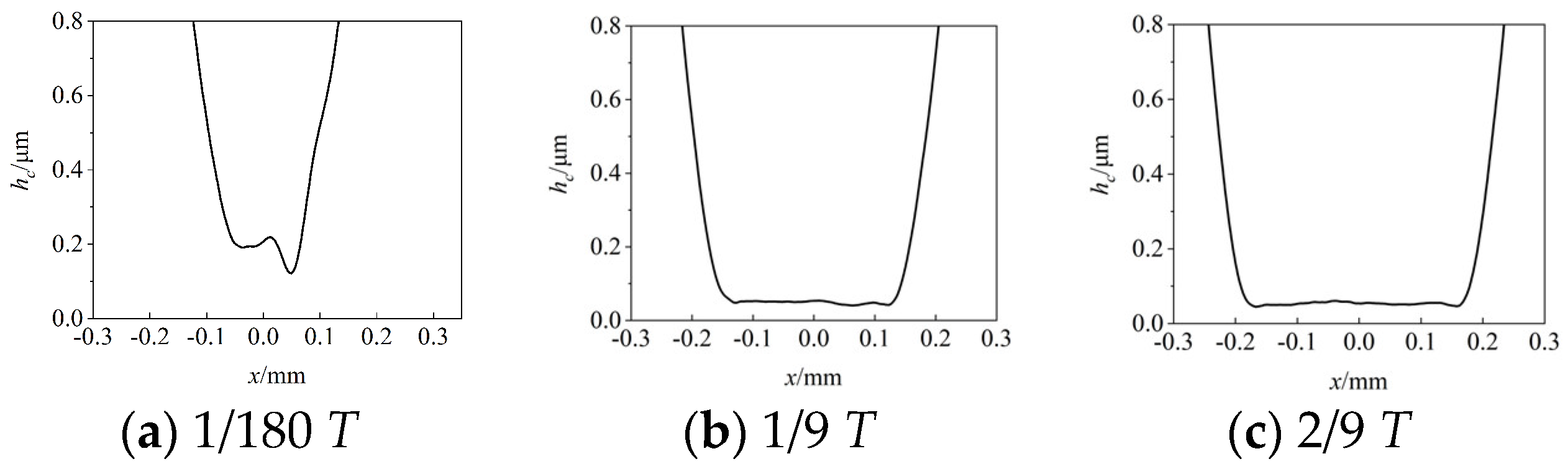
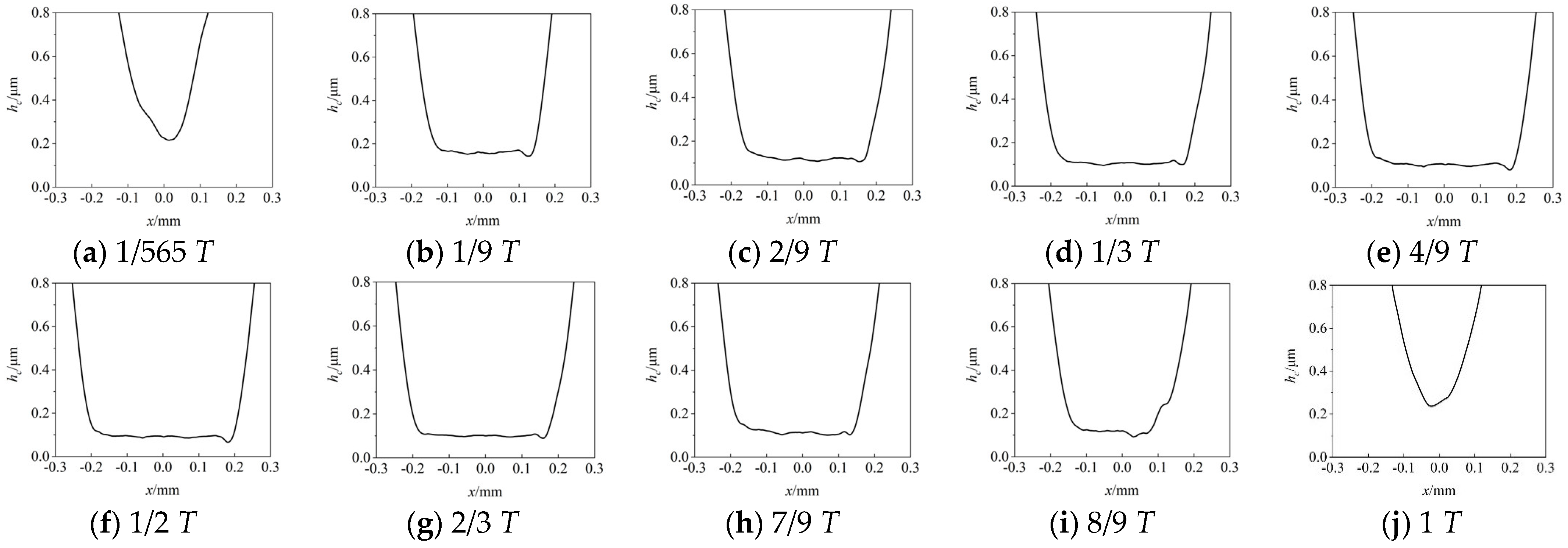
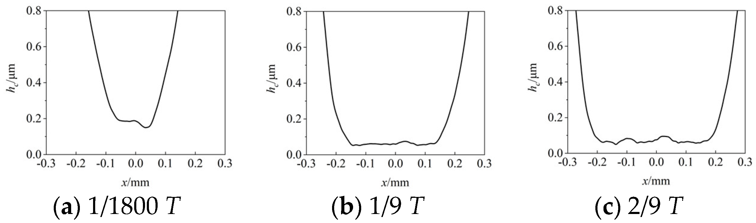
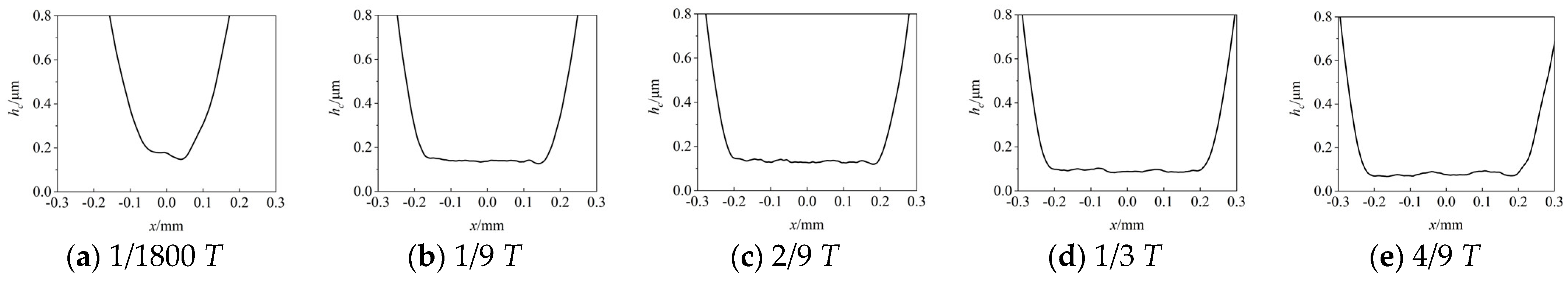
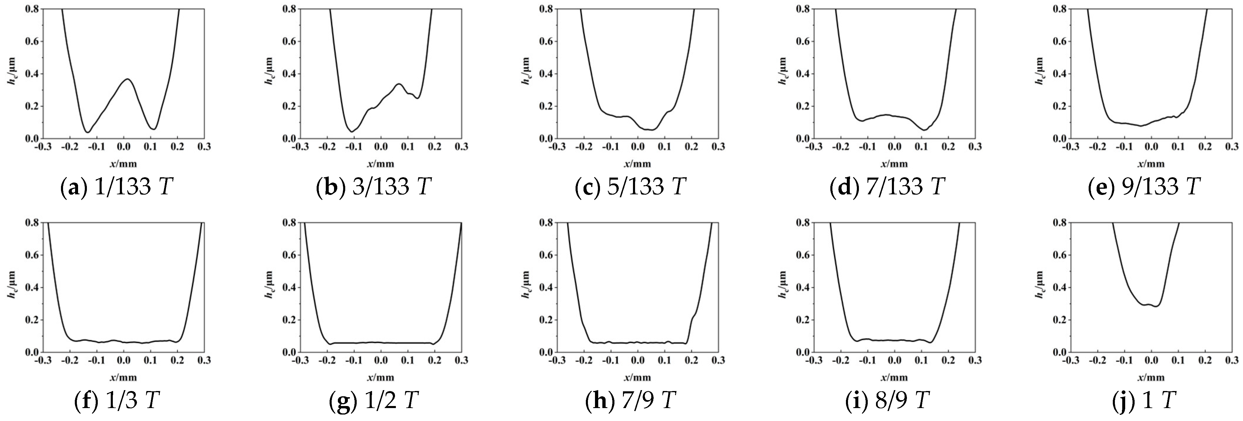
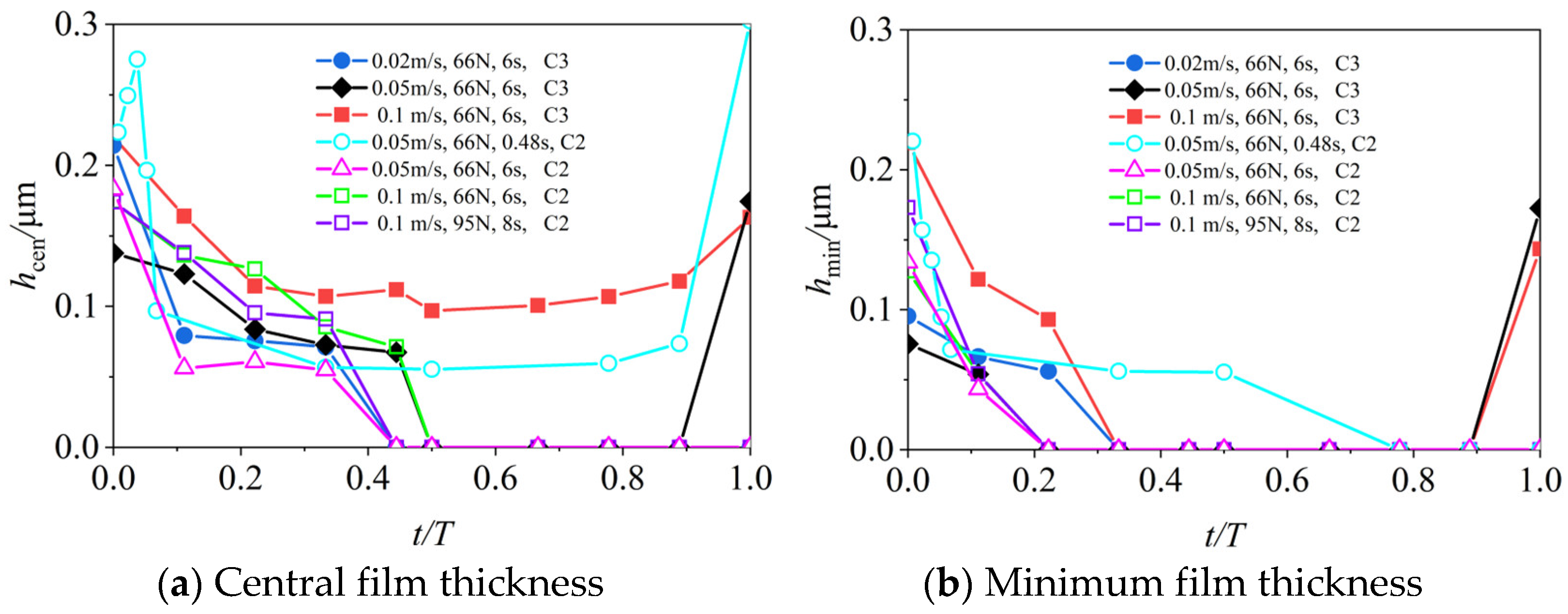
3.4. Central and Minimum Film Thicknesses

Figure 20 shows the comparison of the central and minimum film thicknesses in the loading–unloading process in the above tests. The horizontal coordinate is the dimensionless parameter, t is the time, and T is the impact period. In Figure 20a, only Experiment No. 6, i.e., vs = 0.05 m/s, wmax = 66 N, and T = 0.48 s, makes the central film thickness experience a rapid increase before dropping. At the position of t/T = 0.37–0.7 during the impact process, the central film thicknesses of Experiment Nos. 3 and 4 remained basically unchanged, and then the values were gradually increased. The value of the other five curves also decreased during the impact, but because of the direct contact, the value of the central film thickness decreased to 0. The variation behavior regarding the minimum film thickness was relatively simple for experiments 1~3 and 5~7, and it decreased rapidly at the initial stage of impact and then reached 0 quickly. Figure 20 shows that the Centoplex 3 grease is favorable because its NLGI grade is higher. Moreover, a short working period is recommended.

4. Conclusions

The authors built a variable load optical interference test rig, and then completed impact-sliding optical interference experiments using two complex lithium grease types: Centoplex 3 and Centoplex 2EP. The occurrence and development of impact-sliding composite wear was observed. The conclusions are summarized as follows:
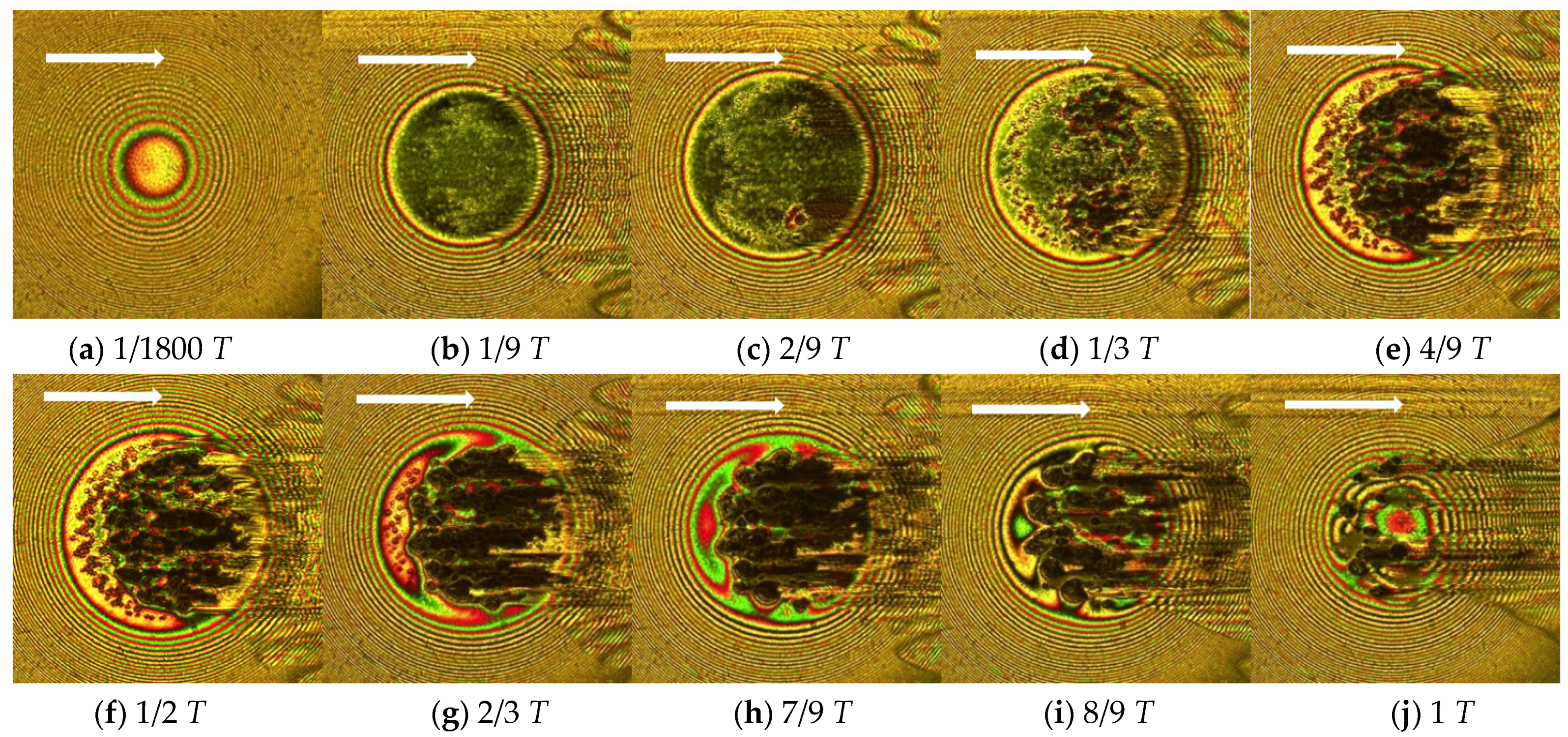
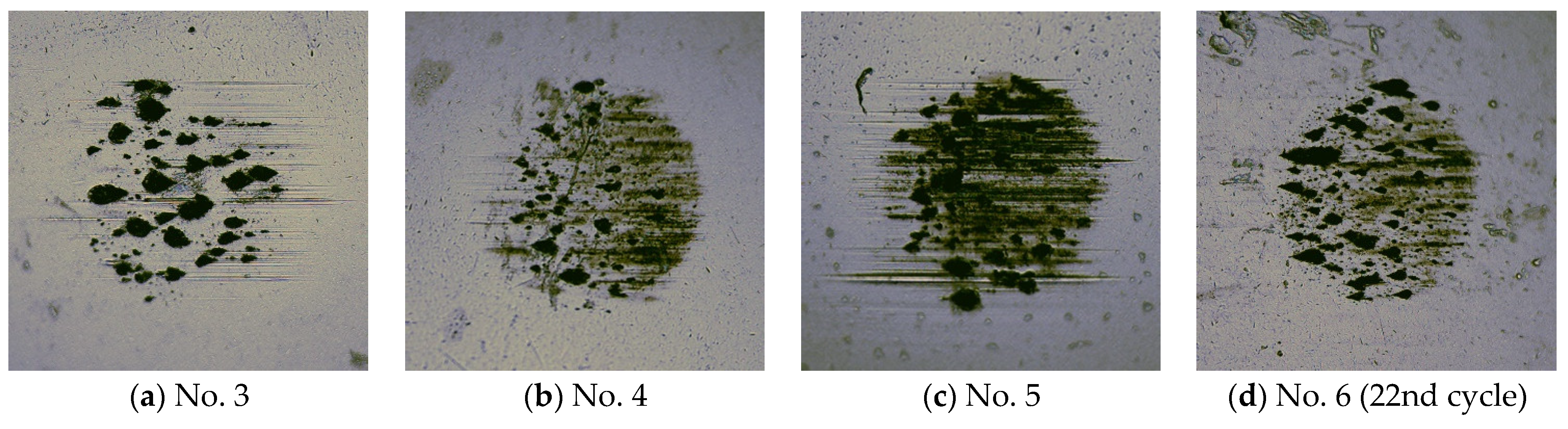
  • The sliding speed affects the position of the wear. When the sliding speed of the glass disk is low, due to the thin film thickness formed, multiple direct contacts of asperity peaks occur simultaneously in the contact area, and gradually expand into pieces, resulting in adhesive wear. With a higher sliding speed, wear occurs first at the side lobes of the horseshoe shape and causes surface scratches in the subsequent movements. Both types of wear occur when the sliding speed is modest.
  • During the impact process, due to the nature of the sliding speed, the wear not only occurs during the linear loading process, but also continues to occur during the linear load reduction process. The lower the consistency of the grease, the more severe the wear. When the maximum value of the load increases, the impact time is prolonged, and the degree of wear is more severe.
  • The current experiments show that the superiority of grease lubrication—shown under the pure rolling condition at a lower speed—is lost due to the impact-sliding motion, regardless of whether the sliding speed is lower or higher. If the working period is long, obvious or significant surface wear occurs in the first working cycle. A shorter working period is beneficial due to the transient effect. However, after several working cycles, obvious surface wear will still be seen.
  • These experiments simulated the slide-impact working condition under a grease-lubricated point contact scheme, and the wear mechanism was also investigated, providing valuable information for the further exploration of composite wear through impact motion. Great attention should be paid to the occurrence of sliding-impact wear when employing grease lubrication, since such working conditions are common in industrial applications.
  • For metal–metal contacts, experiments that replace the glass disk with a steel disk may have a significant impact. As a part of the authors’ research plan, surface damage in steel–steel contacts will be investigated in the future. Moreover, a mixed EHL mathematical model should be established for further investigation.

Author Contributions

Conceptualization, J.W. and R.Z.; methodology, Z.L. and Y.H.; software, Z.L.; validation, Y.H. and J.W.; formal analysis, J.W. and Z.L.; investigation, Z.L.; resources, Z.L.; data curation, Z.L. writing—original draft preparation, Z.L.; writing—review and editing, J.W.; visualization, Z.L.; supervision, J.W.; project administration, J.W.; funding acquisition, J.W. All authors have read and agreed to the published version of the manuscript.

Funding

The authors have disclosed a receipt of the following financial support for the research, authorship, and/or publication of this article: This work was supported by the National Natural Science Foundations of China (51875298) and Shandong Provincial Natural Science Foundation (ZR2019MEE040).

Institutional Review Board Statement

Not applicable.

Informed Consent Statement

Not applicable.

Data Availability Statement

Not applicable.

Acknowledgments

The authors are grateful to Weidong Xie for the support on data collection.

Conflicts of Interest

The authors declared no potential conflict of interest with respect to the research, authorship, and/or publication of this article.

References

  1. Kaneta, M.; Wang, J.; Guo, F.; Krupka, I.; Hartl, M. Effects of loading process and contact shape on point impact elastohydrodynamics. Tribol. Trans. 2012, 55, 772–781. [Google Scholar] [CrossRef]
  2. Fryza, J.; Sperka, P.; Kaneta, M.; Krupka, I.; Hartl, M. Effects of lubricant rheology and impact speed on EHL film thickness at pure squeeze motion. Tribol. Int. 2017, 106, 1–9. [Google Scholar] [CrossRef]
  3. Wang, J.; Venner, C.H.; Lubrecht, A.A. Central film thickness prediction for line contacts under pure impact. Tribol. Int. 2013, 66, 203–207. [Google Scholar] [CrossRef]
  4. Wang, J.; Wang, N.; Yang, P.R.; Kaneta, M.; Lubrecht, A.A. A theoretical simulation of thermal elastohydrodynamic lubrication for a Newtonian fluid in impact motion. Tribol. Int. 2013, 67, 116–123. [Google Scholar] [CrossRef]
  5. Wu, D.; Wang, J.; Yang, P.R.; Lubrecht, T. Effect of oil starvation on the isothermal impact problem. Proc. Inst. Mech. Eng. Part J J. Eng. Tribol. 2018, 232, 1332–1339. [Google Scholar] [CrossRef]
  6. Wang, Y.; Shi, X.Y.; Cai, L.J.; Zhou, Z.R. Development of a new small load testing machine for impact wear and testing of its characteristics. Tribology 2007, 27, 487–491. [Google Scholar]
  7. Wang, J.; Lu, L.; Ji, Z. A study on the impact wear behaviors of 40Cr steel. Jpn. Soc. Tribol. 2015, 10, 273–281. [Google Scholar] [CrossRef] [Green Version]
  8. Ji, Z.; Wang, J.; Xu, Z. Impact—Induced damage behavior of GCrl5 steel under different lubrication states. J. Mater. Prot. 2014, 7, 36–37+71. [Google Scholar]
  9. Wang, N.; Lu, S.; Wang, J. Experimental study on impact wear of GCr15 steel with grease lubrication. Lubr. Eng. 2014, 39, 32–37. [Google Scholar]
  10. Ren, Z.Q.; Zhang, B.B.; Wang, J. Elastohydrodynamic lubrication in line contact reciprocating motion under impulse load. Lubr. Eng. 2013, 38, 28–34. [Google Scholar]
  11. Yin, M.G.; Cai, Z.B.; Yu, Y.Q.; Zhu, M.H. Impact-sliding wear behaviors of 304SS influenced by different impact kinetic energy and sliding velocity. Tribol. Int. 2020, 143, 106057. [Google Scholar] [CrossRef]
  12. Tan, D.Q.; Mo, J.L.; He, W.F.; Luo, J.; Zhang, Q.; Zhu, M.H.; Zhou, Z.R. Suitability of laser shock peening to impact-sliding wear in different system stiffnesses. Surf. Coat. Technol. 2019, 358, 22–35. [Google Scholar] [CrossRef]
  13. Yin, M.G.; Cai, Z.B.; Zhang, Z.X.; Yue, W. Effect of ultrasonic surface rolling process on impact-sliding wear behavior of the 690 alloy. Tribol. Int. 2020, 147, 105600. [Google Scholar] [CrossRef]
  14. Motion Control System of Optical EHL Test Rig Based on PLC and Kingview Software. 2015. Available online: http://www.paper.edu.cn (accessed on 26 January 2015).
  15. Han, Y.M.; Wang, J.; Wang, S.S.; Zou, Q. Response of grease film at low speeds under pure rolling reciprocating motion. Friction 2020, 8, 115–135. [Google Scholar] [CrossRef]
  16. Liu, H.C.; Guo, F.; Guo, L.; Wong, P.L. A dichromatic interference intensity modulation approach to measurement of lubricating film thickness. Tribol. Lett. 2015, 58, 15. [Google Scholar] [CrossRef]
  17. Han, Y.M.; Wang, J.; Jin, X.Y.; Wang, S.S.; Zhang, R. Effects of slide-roll ratio and varying velocity lubrication performance of grease at low speed. Proc. Inst. Mech. Eng. Part J J. Eng. Tribol. 2021, 235, 2122–2136. [Google Scholar] [CrossRef]
  18. Gohar, R.; Cameron, A. Optical measurement of oil film thickness under elastohydrodynamic lubrication. Nature 1963, 200, 458–459. [Google Scholar] [CrossRef]
  19. Gohar, R.; Cameron, A. The mapping of elastohydrodynamic contacts. ASLE Trans. 1967, 10, 215–225. [Google Scholar] [CrossRef]
  20. Hamrock, B.J.; Dowson, D. Isothermal elastohydrodynamic lubrication of point contacts: Part 1—Theoretical formulation. J. Lubr. Technol. 1976, 98, 223–229. [Google Scholar] [CrossRef]
  21. Hamrock, B.J.; Dowson, D. Isothermal elastohydrodynamic lubrication of point contacts: Part II—Ellipticity parameter results. J. Lubr. Technol. 1976, 98, 375–383. [Google Scholar] [CrossRef]
  22. Kaneta, M.; Nishikawa, H.; Kameishi, K.; Sakai, T. Effects of elastic moduli of contact surfaces in elastohydrodynamic lubrication. ASME J. Tribol. 1992, 114, 75–80. [Google Scholar] [CrossRef]
  23. Kaneta, M.; Nishikawa, H.; Kanada, T.; Matsuda, K. Abnormal phenomena appearing in EHL contacts. ASME J. Tribol. 1996, 118, 886–892. [Google Scholar] [CrossRef]
  24. Qu, S.; Yang, P.; Guo, F. Theoretical investigation on the dimple occurrence in the thermal EHL of simple sliding steel-glass circular contacts. Tribol. Int. 2000, 33, 59–65. [Google Scholar] [CrossRef]
  25. Yang, P.; Qu, S.; Kaneta, M.; Nishikawa, H. Formation of steady dimples in point TEHL contacts. ASME J. Tribol. 2001, 123, 42–49. [Google Scholar] [CrossRef]
Figure 1. Schematic diagram of varying load ball–disk test rig.
Lubricants 10 00284 g001
Figure 2. Variation of the loading curve.
Lubricants 10 00284 g002
Figure 3. Interferograms of occurrence of surface wear during loading–unloading process. (vs = 0.02 m/s, wmax = 66 N, and T = 6 s, for Centoplex 3 grease).
Lubricants 10 00284 g003
Figure 4. Three mid-section film thicknesses (vs = 0.02 m/s, wmax = 66 N, and T = 6 s, for Centoplex 3 grease).
Lubricants 10 00284 g004
Figure 5. Interferograms depicting occurrence of surface wear during loading–unloading process (vs = 0.05 m/s, wmax = 66 N, and T = 6 s, for Centoplex 3 grease).
Lubricants 10 00284 g005
Figure 6. Five mid-section film thickness. (vs = 0.05 m/s, wmax = 66 N, and T = 6 s for Centoplex 3 grease).
Lubricants 10 00284 g006
Figure 7. Interferograms of occurrence of surface wear during loading–unloading process (vs = 0.1 m/s, wmax = 66 N, and T = 6 s for Centoplex 3 grease).
Lubricants 10 00284 g007aLubricants 10 00284 g007b
Figure 8. Mid-section film thickness (vs = 0.1 m/s, wmax = 66 N, and T = 6 s for Centoplex 3 grease).
Lubricants 10 00284 g008
Figure 9. Interferograms of occurrence of surface wear during loading–unloading process (vs = 0.05 m/s, wmax = 66 N, and T = 6 s for Centoplex 2EP grease).
Lubricants 10 00284 g009
Figure 10. Three mid-section film thickness (vs = 0.05 m/s, wmax = 66 N, and T = 6 s for Centoplex 2EP grease).
Lubricants 10 00284 g010
Figure 11. Interferograms of occurrence of surface wear during loading–unloading process. (vs = 0.1 m/s, wmax = 66 N, and T = 6 s for Centoplex 2EP grease).
Lubricants 10 00284 g011
Figure 12. Five mid-section film thicknesses (vs = 0.1 m/s, wmax = 66 N, and T = 6 s for Centoplex 2EP grease).
Lubricants 10 00284 g012
Figure 13. Interferograms of occurrence of surface wear during loading–unloading process. (vs = 0.05 m/s, wmax = 66 N, and T = 0.48 s for Centoplex 2EP grease).
Lubricants 10 00284 g013
Figure 14. Mid-section film thickness (vs = 0.05 m/s, wmax = 66 N, and T = 0.48 s for Centoplex 2EP grease).
Lubricants 10 00284 g014
Figure 15. Interferograms of occurrence of surface wear during loading–unloading process in 5th cycle (vs = 0.05 m/s, wmax = 66 N, and T = 0.48 s for Centoplex 2EP grease).
Lubricants 10 00284 g015aLubricants 10 00284 g015b
Figure 16. Interferograms of occurrence of surface wear during loading–unloading process in 22nd cycle (vs = 0.05 m/s, wmax = 66 N, and T = 0.48 s for Centoplex 2EP grease).
Lubricants 10 00284 g016
Figure 17. Interferograms of occurrence of surface wear during loading–unloading process (vs = 0.1 m/s, wmax = 95 N, and T = 8 s for Centoplex 2EP grease).
Lubricants 10 00284 g017aLubricants 10 00284 g017b
Figure 18. Four mid-section film thickness profiles (vs = 0.1 m/s, wmax = 95 N, and T = 8 s for Centoplex 2EP grease).
Lubricants 10 00284 g018
Figure 19. Optical microscope images of wear surface of steel ball.
Lubricants 10 00284 g019
Figure 20. Comparison of central and minimum film thickness.
Lubricants 10 00284 g020
Table 1. Parameters of ball and disk.
Glass DiskSteel Ball
MaterialK9 glassGCr15 steel
Diameter (mm)15025.4
Thickness (mm)15
Elastic modulus (GPa)81208
Poisson ratio0.2080.3
Table 2. Parameters of grease types.
PropertiesCentoplex 3Centoplex 2EP
Base oilMineral oilMineral oil
ThickenerLithium soapLithium soap
Applicable temperature range (°C)−16 to 150−20 to 130
Base oil viscosity (40 °C mm2/s)100180
Base oil viscosity (100 °C mm2/s)1014
Penetration (×0.1 mm)220 to 250265 to 295
NLGI32
Table 3. Experimental parameters.
Experiment
No.
Sliding Speed
(vs/m⋅s−1)
Maximum Load (wmax/N)Period
(T/s)
Grease Type
10.02666Centoplex 3
20.05666Centoplex 3
30.1666Centoplex 3
40.05666Centoplex 2EP
50.1666Centoplex 2EP
60.05660.48Centoplex 2EP
70.1958Centoplex 2EP
Publisher’s Note: MDPI stays neutral with regard to jurisdictional claims in published maps and institutional affiliations.

