1. Introduction
Hertzian formulas are universally used for the evaluation of deformation and stress of non-conforming mechanical pairs, including the counterformal and the slightly conformal ones, to estimate component stiffness and durability. Appealing for their simplicity, Hertzian formulas, however, present some limitations in their applications to real contacts, related to the hypotheses on which they are based [
1], such as absence of friction, small contact area, and bodies equivalent to half-spaces, as will be better explained in the following section. As Mostofi and Gohar observed in [
2], pressure distribution, contact arc extent, and deflection for the elastic contact of a long roller and a cylindrical hole depend on the degree of conformity of the two bodies and Hertz’s theory should not be used when the arc dimensions are of the same order as the radii of curvature, as its assumptions are violated. Actually, there are cases of applications to quite conformal contacts, though not satisfying the hypothesis that the deformed zone is much smaller than the dimension of the contacting bodies. Significant examples of the application of these formulas for the evaluation of the stiffness of the pivots of tilting pad journal bearings (TPJB) are reported by Kirk and Reedy in [
3].
Typically, Hertzian formulas are used also for elastohydrodynamic (EHD) contacts, for instance rolling bearings and gears [
4,
5], because pressure distribution has been shown to be quite similar to the Hertzian pressure profile, particularly for the heavily loaded contacts with the exception of the inlet hydrodynamic trail and the secondary pressure peak at the exit constriction [
6,
7]. Therefore, the equivalent radius and elastic modulus are used for the evaluation of the minimum film thickness and the Hertzian formulas are used to calculate the deformations of rolling bodies and teeth; Hertz’s contact ellipse and maximum pressure are commonly taken as reference for EHD solutions and experimental observations.
Quite a few researchers observed and tried to overcome the limitations of Hertz’s theory with analytical and numerical approaches. Sun and Hao [
8] dealt with non-conformal and almost conformal contact of ball and ball–socket and compared the results of finite element (FE) analyses and Hertz’s contact theory. Fang et al. [
9] proposed a new universal approximate model for frictionless conformal and non-conformal spherical contacts, based on the combination of analytical and numerical methods. Such a method was adopted in [
10] to investigate the free-edge effect in spherical plain bearings, and by He et al. [
11] to analyze the effects of external load, radius clearance, and material parameters on the contact mechanics of roller cone drill bits journal bearings. Yuan et al. [
12] studied the effects of normal loads and friction coefficients on the distribution of contact stress in spherical plain bearings using theoretical methods and FE simulation. In [
13], Rahnejat et al. proposed a generic contact mechanics analytical approach, applicable to both conformal and non-conformal contacts, for the determination of sub-surface stresses. Askari, in [
14], proposed mathematically closed-form contact models for non-Hertzian soft and conformal contacts, using a set of independent Kelvin–Voigt elements spread all over the contact surfaces, validating them through FE analysis. Blanco-Lorenzo et al. [
15] investigated the effects of conformity on local contact related quantities for the wheel–rail pair with FE simulations and by adapting Kalker’s rolling contact theory. Tian et al. [
16] reviewed analytical and numerical contact models applied to dry and lubricated clearance joints. Significant under- and overestimations of the contact radius and maximum contact pressure according to Hertz’s theory, in spherical indentation of soft elastic solids undergoing large deformations, are shown in [
17], using nanoindentation tests and FE analysis.
In this paper the applicability of the Hertzian formulas to practical cases was investigated. This study was motivated by the non-Hertzian behavior of a tilting pad journal bearing ball-and-socket pivot conforming contact observed by the authors in previous experiments [
18] and by the need of an accurate estimation of the pivot stiffness and a reliable prediction of the bearing dynamic behavior [
19,
20,
21]. It is intended as the starting point to overcome the limitations of the formulas used in common industrial practice [
3]. To better understand the reasons for the differences that can arise between theoretical and FE or experimental results, the hypotheses and the essential steps at the base of the Hertzian formulas are firstly reported. Then, some FE calculations on non-conformal and conformal spherical bodies with different geometry, load, materials, and boundaries are conducted and compared with the results of the formulas focusing on deformations. Finally, some experimental results on the TPJB ball-and-socket pivot are reported.
2. Hertzian Formulas for Circular Contacts
Contact mechanics is based on the work of Hertz in 1882 [
1] whose theory is restricted to frictionless surfaces and perfectly elastic solid.
For non-conforming elastic bodies in contact over an area whose dimensions are small compared with the radii of curvature of the undeformed surfaces, the stresses may be calculated with good approximation by considering each body as a semi-infinite elastic solid bounded by a plane surface; this is the half-space theory that is commonly used in elastic contact stress theory [
22].
The main assumptions of the Hertzian theory are recalled below:
the bodies are homogeneous, isotropic, and non-conforming;
the bodies are elastic and the strains are small so that the theory of elasticity can be applied;
the elastic bodies in contact are assumed to be semi-infinite elastic half-spaces; this means that contact dimensions and extent of deformation are far smaller than the geometrical dimensions of the contacting bodies;
the profiles may be represented by a second order law;
the surfaces are frictionless;
adhesive forces are ignored;
the surfaces have negligible roughness.
Two additional timely assumptions may be included:
there are no thin coatings on the surfaces;
the surfaces are relatively hard.
It’s worth pointing out that theories were successively developed overcoming some of these assumptions. According to Gohar [
5] and Johnson [
23], Hertz’s theory is however accurate for usually finished surfaces and typical friction coefficients. Rough surfaces and friction may be included by using the Greenwood and Tripp model for the case of assumed Gaussian surface topography [
24]. The Johnson–Kendall–Roberts (JKR) theory included the adhesion between the bodies [
25].
The starting equations are the ones of elasticity, as reported, for example, in [
5] and [
22]. Usually the displacements and the stresses produced by a load distributed over a part of the boundary of a semi-infinite solid are calculated by superposition, starting from the case of a concentrated force. Then, an integration is made considering the shape of the surface and the distribution of pressure.
In the case of an axisymmetric pressure distribution, as it can be in a sphere-plane contact, the Hertzian pressure is a semi-ellipsoid acting on a circular area. Such a result, strictly valid for an infinite solid bounded by a plane surface, is however applicable to a body neither infinite nor bounded by a plane. This is possible if the deflection at the center of the circle is small in comparison with the radius of the contact area and if the latter is small in comparison with the radius of curvature of the bodies in contact. The stresses must be within the elastic limit. For the sake of simplicity, the case of a sphere with radius
R, Young’s modulus
E1, and Poisson’s ratio
ν1 pressed with a load
F against a plane (
E2,
ν2), as reported in [
26], will be now considered. In the ideally rigid case (not deformed bodies) the sphere can be well approximated with a paraboloid in the zone close to the contact point. Details of the development of the Hertzian formulas for the above case are given in
Appendix A, while only the commonly used resulting ones are reported also in this section.
The maximum of the Hertzian pressure is given by
where
a, the radius of the circular contact area, is given by
and the equivalent elastic modulus
E’ is defined as
As far as deformation is concerned, the rigid body approach
δ of the two bodies can be evaluated by the formula:
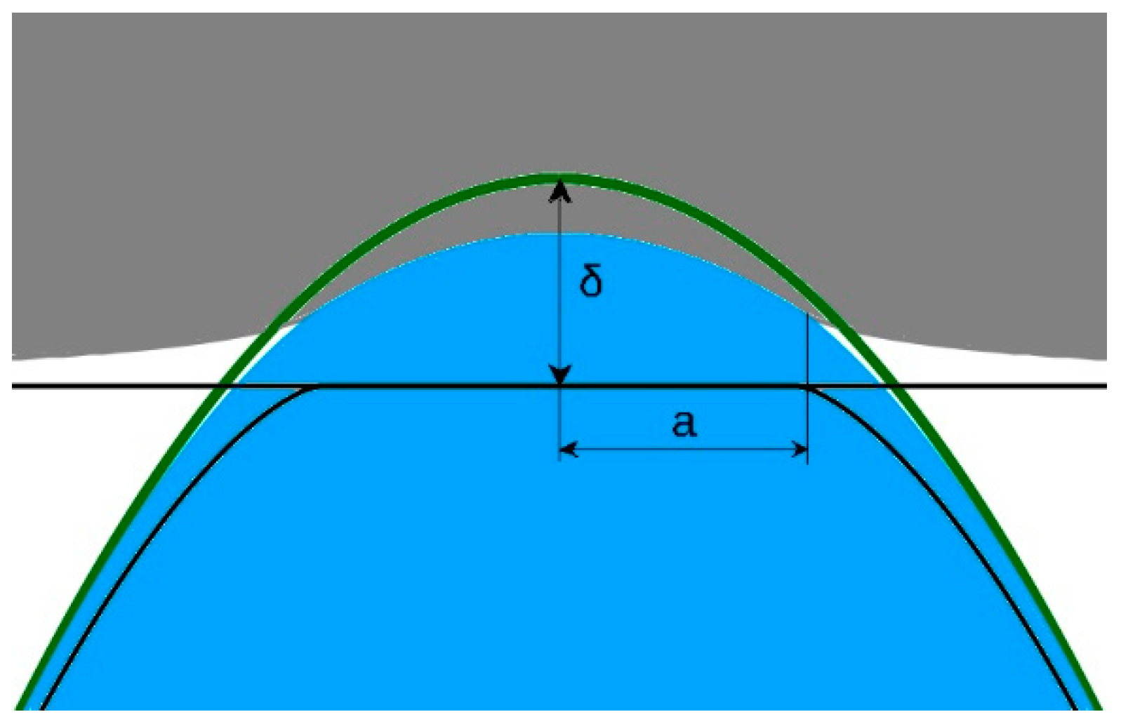
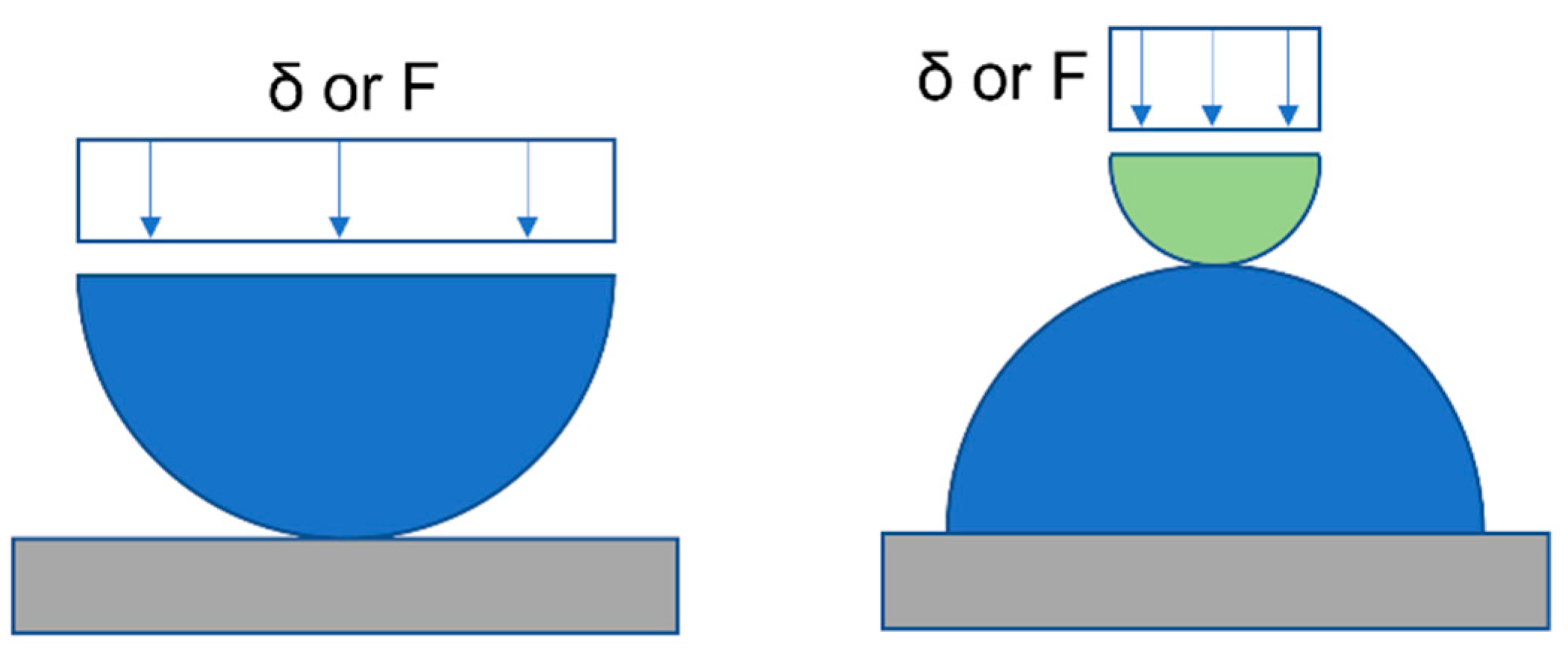
As shown in
Figure 1, the contact between the two deformable bodies can be seen as an equivalent contact between a rigid plane and a deformable body to which the equivalent radius and elastic modulus are associated. The rigid body approach
δ corresponds to the distance of the green and black lines at the axis of symmetry.
Equations (2) and (4) can also be used if both contacting bodies have a curvature by substituting
R with an equivalent radius
R’ defined as
The positive sign has to be chosen in Equation (5) if the centers of curvature of the two spheres are in opposite half-spaces with respect to the plane tangent to the spheres at their theoretical contact point (counter-conformal contact), while the negative sign has to be used for the other case, corresponding to a sphere in a spherical seat (conformal contact). In the latter case,
R’ can be also expressed as a function of the radial clearance
c between the two bodies:
with
R1 =
R and
R2 =
R +
c.
Equations (2) and (4) can be written in dimensionless form:
where the ratio
is the dimensionless load for point contacts.
Note that, as remarked above, Hertz’s theory is usually considered accurate if also δ << a in addition to a << R.
In the above cases, the load is applied far enough from the contact zone so that the applied load distribution and local deformation do not interfere with the body contact zone deformation. In addition, it is not apparent which points can be considered as reference points for the evaluation of the approach of the two touching bodies. This aspect was analyzed in the FE simulations whose results are reported in
Section 4 and
Section 5. First, the simulations were validated by comparison with Hertz’s formulas for non-conformal Hertzian contacts; then, some hypotheses were dropped to check the extent of the applicability of Hertz’s theory to such contacts.
3. Experimental Results for a Conformal Real Spherical Pair
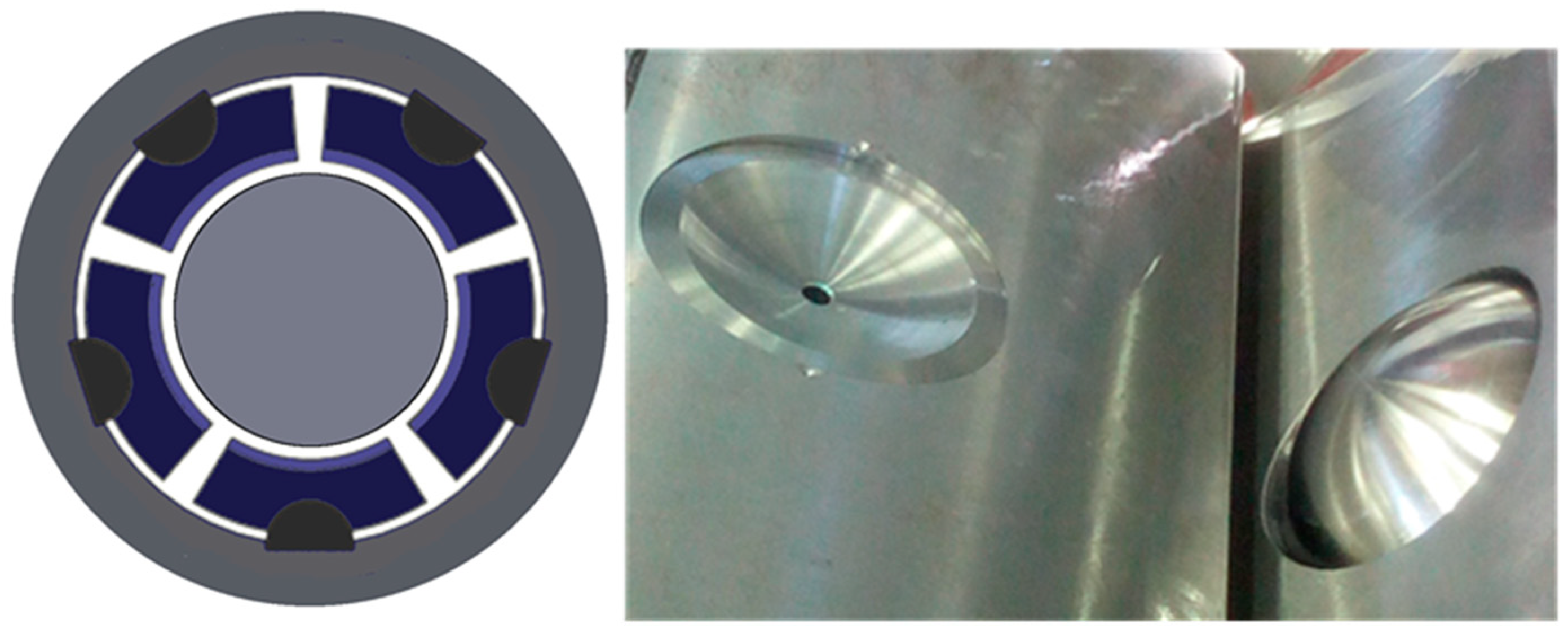
A significant example of the application of Hertzian formulas to a real conformal spherical pair is the ball-and-socket pivot of TPJBs made of a spherical cap and a spherical seat as shown in
Figure 2.
The bearing dynamic behavior is greatly influenced by the pivot stiffness whenever it is of the same order of magnitude as the oil film stiffness [
19,
20,
21]. The pivot stiffness is commonly evaluated using Hertzian formulas as reported in [
3], and in particular, from the Hertzian relation between load and displacement.
TPJB pivot stiffness was determined experimentally in [
27,
28] by loading a single pad of the bearing assembly, pressing together the bearing and the shaft in dry conditions, and measuring the relative displacement. The thusly estimated stiffness was then used in TPJB numerical codes to simulate the system rotordynamic behavior, improving the predictions compared with the ones based on Hertzian formulas.
Novel experimental equipment was set up and a procedure devised for determining the stiffness of a single TPJB ball-and-socket pivot by Ciulli et al. [
18]. The test rig was tuned by means of a series of tests and the experimental results were compared with the theoretical ones obtained with Hertzian formulas. The test articles were the components of a 280 mm diameter TPJB pad pivot. The spherical cap and the spherical seat were made of steel with nominal sphere diameter of 127 mm with micrometric tolerance on sphericity and a smooth surface (
Ra < 1 μm). The cap was 20.3 mm high. The seat was 88.8 mm wide and 23.5 mm high, with a spherical 10.28 mm deep cup on top. The diametral clearance range between cap and seat was from 0.046 to 0.104 mm corresponding to relative clearances of 0.036% and 0.082%, respectively.
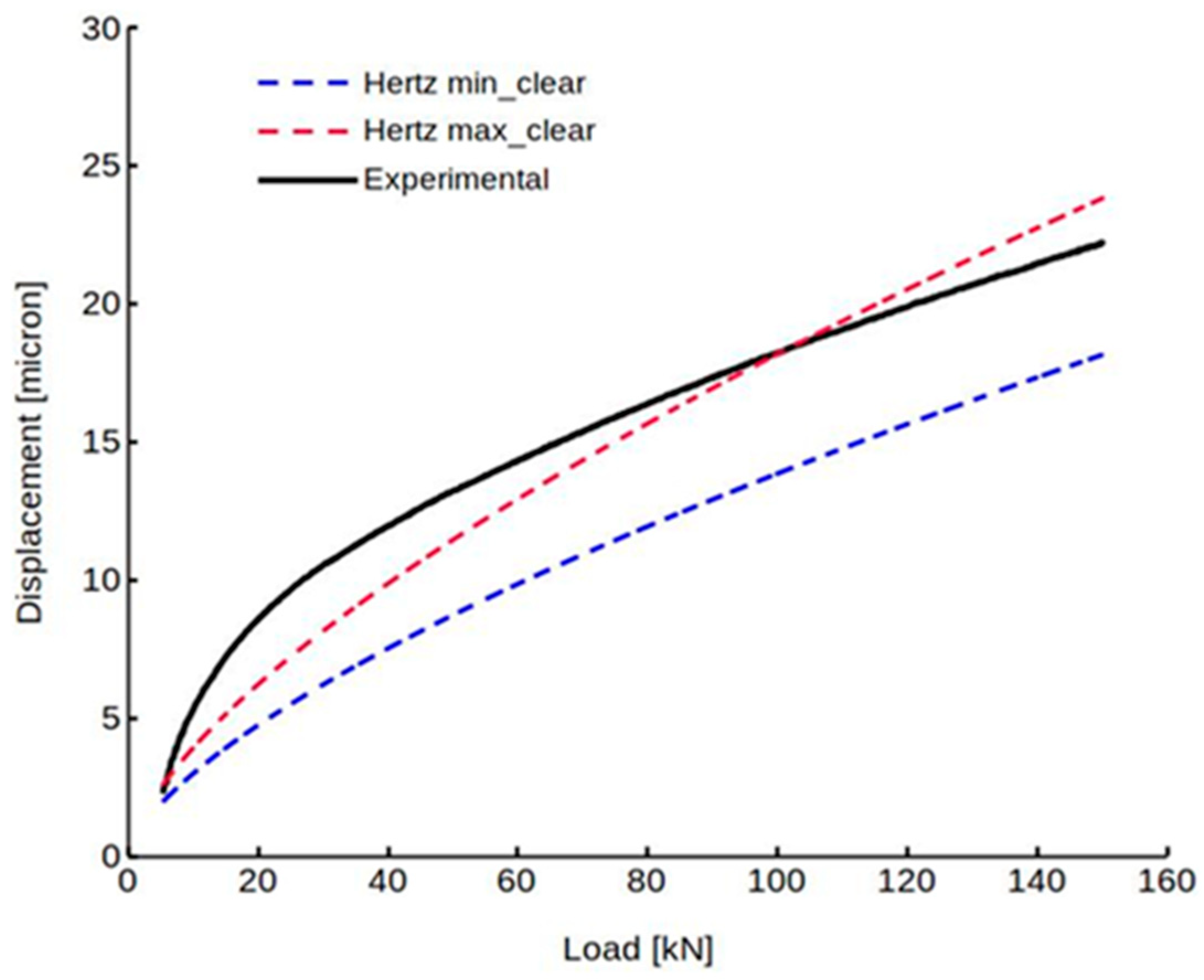
An example of the obtained results is shown in
Figure 3. The displacement is plotted as a function of load. The results obtained with the Hertzian formulas are reported for the minimum and maximum values of the radial clearance
c. It is noteworthy that clearance is very influential, thus the manufacturing process should guarantee tight tolerances and accurate checks. The same results of
Figure 3 are plotted in dimensionless form in
Figure 4. While dimensionless Hertzian results merge in a single curve, the dimensionless experimental curves are different depending on the clearance used. Note that the Hertzian pressures at the maximum tested load of 150 kN are only 22.4 and 38.6 MPa for the minimum and maximum clearance, respectively.
The observed differences with the Hertzian behavior of the ball-and-socket pivot indicated the need to investigate further the displacement and force relation for conforming pairs by varying the geometrical parameters, the materials, the boundary conditions, and the friction coefficient. That was accomplished with a FE approach as reported in the following sections.
4. Numerical Simulation of Non-Conformal Contacts
Some FE calculations of various contact pairs were performed with the commercial structural mechanics software ANSYS Workbench 2021 R2. As a starting point, in order to verify the soundness of the models used and the possible effect of different parameters, such as dimensions and materials, some simulations were made for classical non-conformal contacts.
Due to axisymmetry, only a single plane had to be simulated, reducing the computational cost. Moreover, in the case of a complete sphere pressed by two rigid planes, the symmetry about the central horizontal plane and its constraints were considered, and the axisymmetric model was reduced to half. This reduction was also extended to the case of two elastic spheres in contact even if there was no symmetry about a plane. That was possible due to the negligible deformation of the non-conformal bodies compared with that of the small volume around the point contact, as assumed by Hertz and as will also be shown in the displacement map obtained by FE analysis.
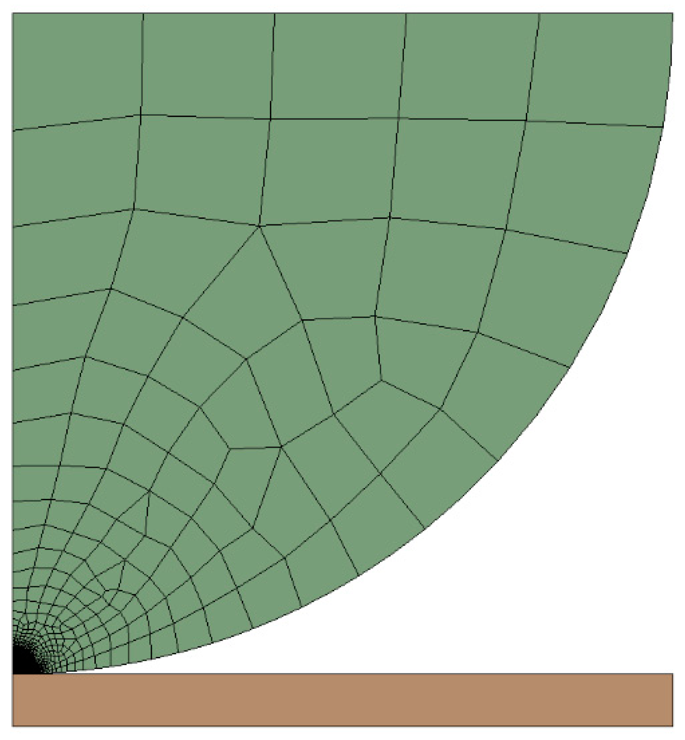
The mesh for non-conformal contacts was generated refining it in the proximity of the contact (
Figure 5). In particular, the maximum element size was 1/5 of the sphere radius. Near the contact, the element size was 3 × 10
−4 of the sphere radius. The total number of elements employed varied between simulations and was approximately 11,000 (3000 for conformal contacts). The plane was modelled by a fixed rigid cylinder, represented by a rectangle in the axisymmetric model. The spheres were linear elastic and the plane was infinitely stiff. All contacts were frictionless unless otherwise specified. Moreover, the contact penetration tolerance was set to 0.1 nm.
A uniform, downward displacement was incrementally applied to the horizontal plane of the half-sphere in the sphere-on-plane case and to that of the upper half-sphere in the sphere-on-sphere case (
Figure 6). The reaction force of the rigid plane or of the lower half-sphere as well as the displacement of the sphere center were provided by the software.
Table 1 reports the data used in the simulations performed for comparison with Hertz’s theory, and
Table 2 reports the adopted material properties values. Simulations were performed imposing a uniform vertical downward displacement to the upper surface, while the horizontal displacement was left free. The displacement range and steps were tuned for each simulation so that the maximum value of displacement corresponded to a non-dimensional pressure (
pHz/
E’) of 2.5 × 10
−3, calculated theoretically using Equation (1) and Equation (4). This pressure corresponded to 1.1 GPa in steel, 0.6 GPa in titanium, and 0.4 GPa in aluminium. The displacement steps were 100, equally spaced.
Table 1 also reports the mean percentage error of the simulation reaction force, calculated by taking the absolute difference between the simulation result and the theoretical value from the Hertzian formula, for the same imposed displacements in the investigated range.
Figure 7 shows an example of the map of deformation in the load direction for a non-conformal case. Zero displacement corresponds to the lower fixed boundary of the seat. The uniform colors over a large zone indicate rigid displacement. It is noteworthy that the non-conformal case localizes non-negligible values of strain in quite a small region around the contact, satisfying the hypothesis of Hertz’s theory.
In all the above cases, the results of the simulations were in good agreement with the theoretical ones since Hertz’ assumptions were complied with. As an example, results from the second simulation of the list, in terms of radius of the contact area, maximum contact pressure, and applied force, as functions of displacement, are given in
Figure 8.
Alternatively, to the uniform displacement, a uniform vertical force was applied on top of the hemisphere and the displacement of the sphere center calculated. As expected, due to the negligibility of the overall body deformations with respect to the local contact ones, the results were similar to the previous ones. Additionally in these cases, the mean error of the simulation results from Hertz’s theory did not exceed 0.5%. Therefore, the following simulations were made imposing displacement.
In addition, other simulations were carried on spherical caps in contact with a rigid plane, with a height
h lower than the sphere radius
R (
Figure 9). The ratio
h/R took the values 0.5, 0.25, and 0.125, and the results seemed to show a negligible influence of this parameter. Again, this can be explained with the negligibility of the overall body deformations with respect to the local contact ones.
In another set of simulations, friction was added to the contact. Usually for lubricated steel on steel, a friction coefficient f = 0.15 can be assumed while for dry steel on steel, a friction coefficient f of approximately 0.5 is reasonable. In the simulations, the friction coefficient was increased up to 0.8. However, substantial differences from the frictionless case were not found even at this high value.
5. Extension to Conformal Contacts
While Hertz’s theory is strictly valid for non-conformal contacts, often in engineering practice [
3], it is used also for conformal contacts (
Figure 10).
The next set of FE simulations in
Table 3 aims to see to which extent this approximation is valid, in particular to see the effects of clearance, seat dimensions, boundary conditions, and friction.
C is the relative radial clearance (
c/R) between the components of the conformal pair. The equivalent radius
R’ ranges from 2 to 50 m, that is, from a slight to a high conformity. The seat has vertical displacement constraints on the lower surface, the cap has imposed vertical displacement or load on its top surface. Both are free in the radial direction unless otherwise specified for the seat (fixed support). The contacts are frictionless unless otherwise specified with the value of the friction coefficient.
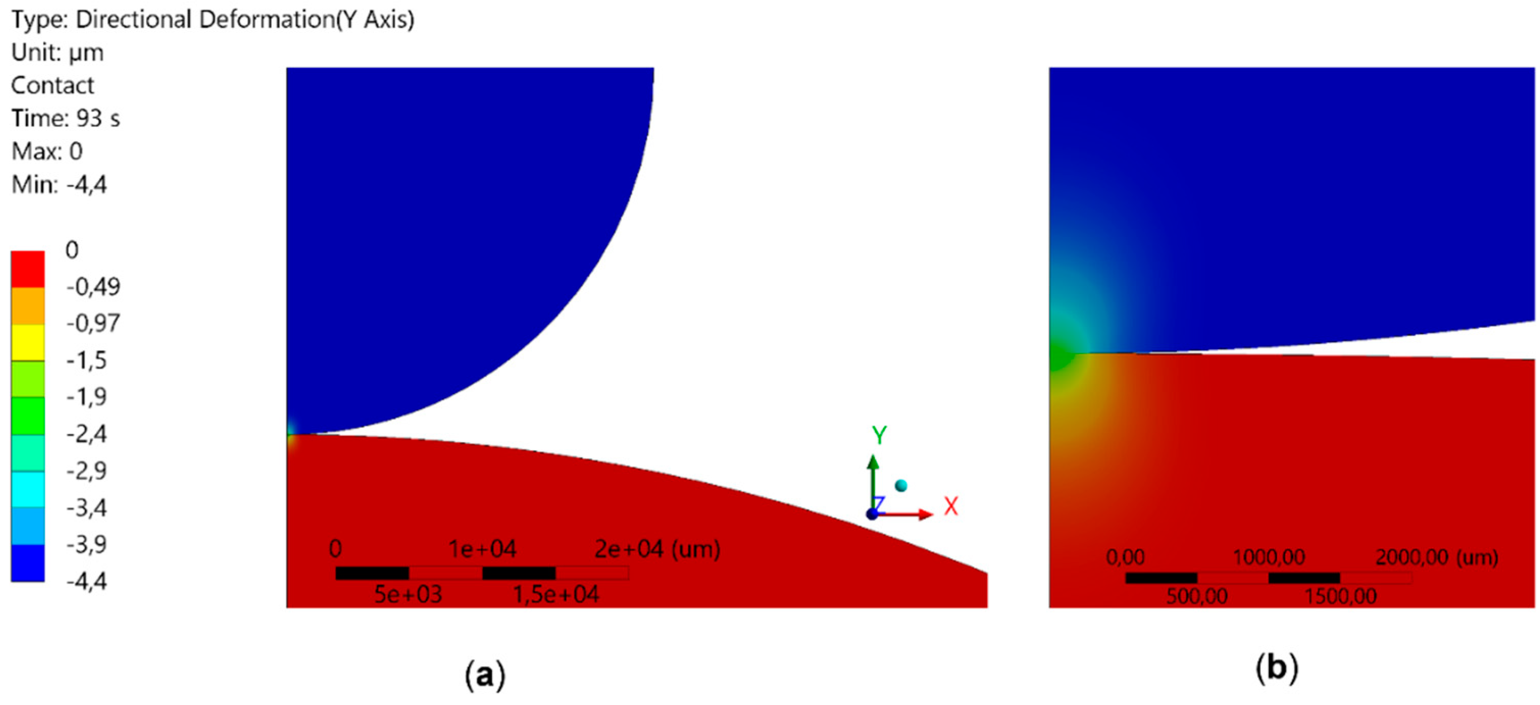
Figure 11 reports an example of the maps of deformation for a conformal case. The force reaction is 195 N. This map can be compared with that of
Figure 7, obtained with the same force. Note that the color scales are different for the two images. Qualitatively, in the conformal case, the contact pressure has a much larger zone of influence. This means that conformal contacts are less likely to satisfy the hypotheses of Hertz’s theory.
To compare results for different clearances, non-dimensional quantities were employed. Two different boundary conditions were investigated, as shown in
Figure 10. In the image on the left, a uniform displacement is imposed, and the reaction force is calculated. In the image on the right, a uniform force is imposed, and the displacement of the center of the sphere is calculated.
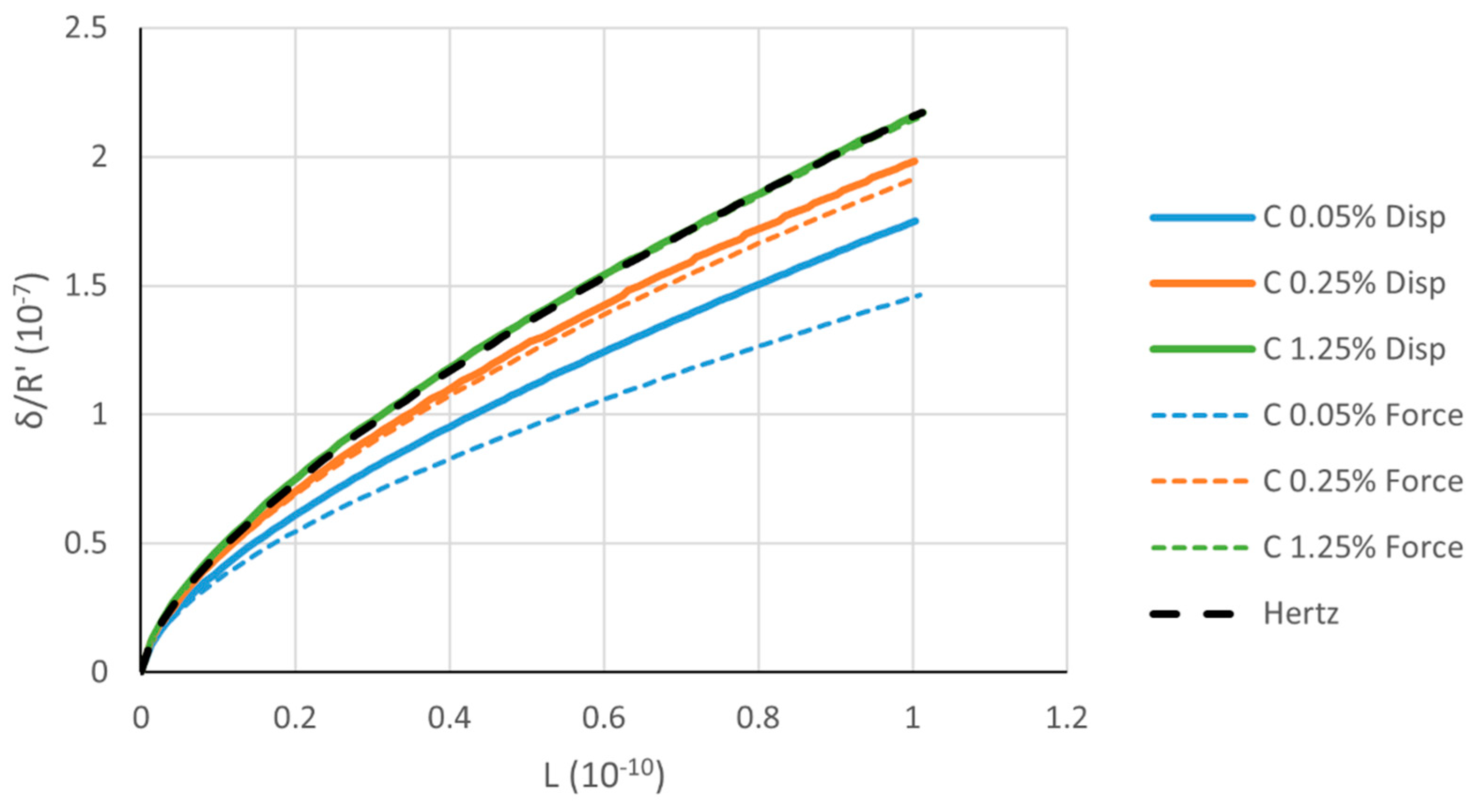
Figure 12 shows the calculated force and displacement for the two boundary conditions. As clearance decreases, the depicted function behavior diverges increasingly from Hertz’s theory. That was to be expected because the smaller the clearance, the more conformal the contact, and the radius of the contact area cannot be considered much smaller than curvature radius. Note that the rigid body approach decreases by decreasing the clearance and that Hertz’s theory provides the highest value.
With respect to the displacement boundary conditions, the values obtained by imposing a uniform force diverge more from Hertz’s theory. An imposed uniform displacement to the upper surface of the elastic body corresponds to what happens to approaching rigid bodies (as assumed by Hertz). On the contrary, a uniform force produces a non-uniform displacement of the upper surface of the elastic body, not consistent with the rigid body approach assumption.
Afterwards, the geometry of the cavity was investigated. In a set of simulations,
b (
Figure 10) was progressively reduced. The results for a relative clearance of 0.25% are reported in
Figure 13. When the seat shrinks, the results differ more from Hertz’s theory. This is related to the reduced compressed material that can be deformed, the base being fixed. In other words, the stiffness of the whole system increases, as confirmed by the rigid body approach that decreases by decreasing
b.
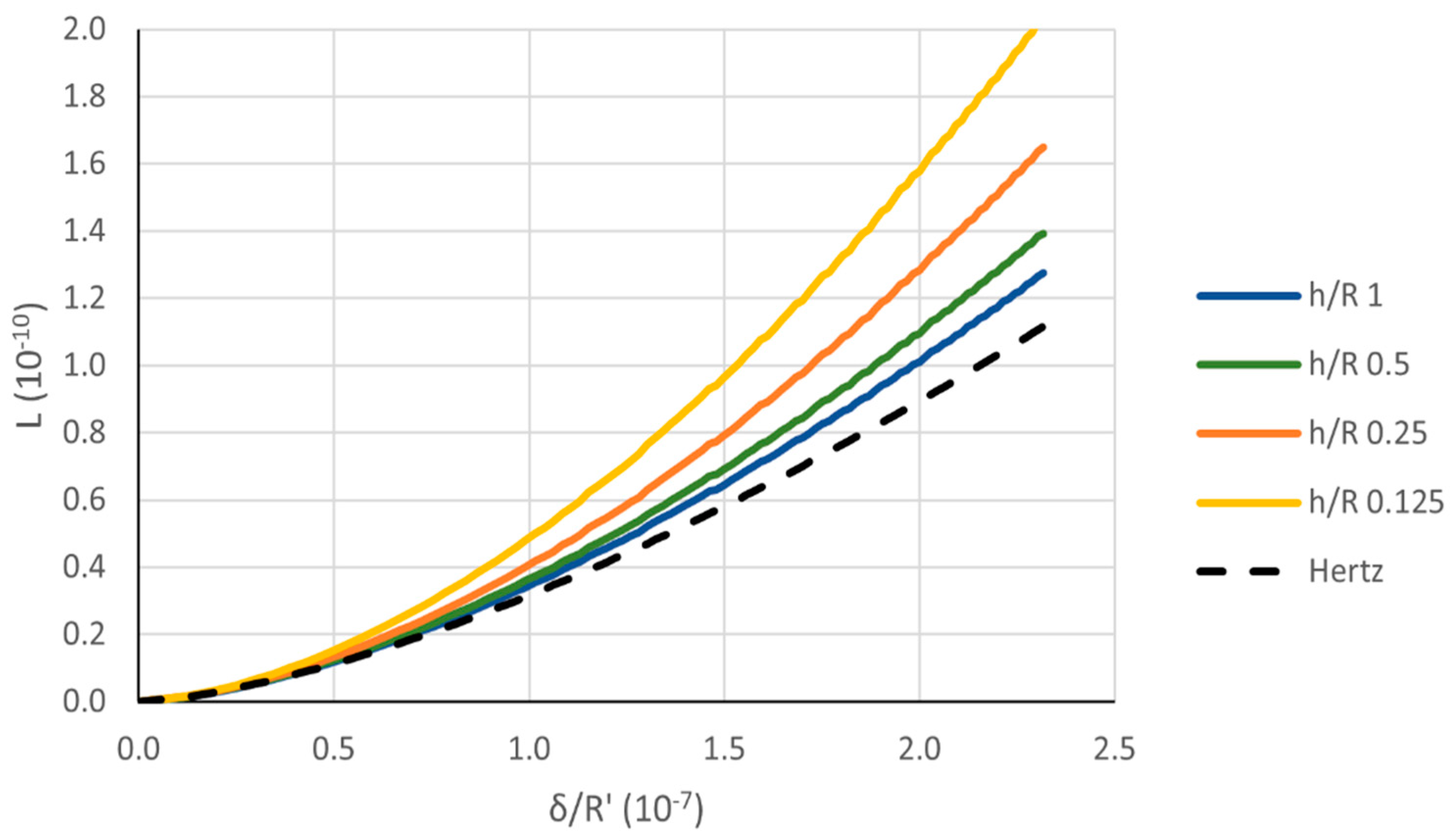
A similar effect is produced by reducing
h. The effect of changing the height of the spherical cap is considerable compared to non-conformal contacts, as shown in
Figure 14 for a relative clearance of 0.25%. Again, the rigid body approach decreases by decreasing
h.
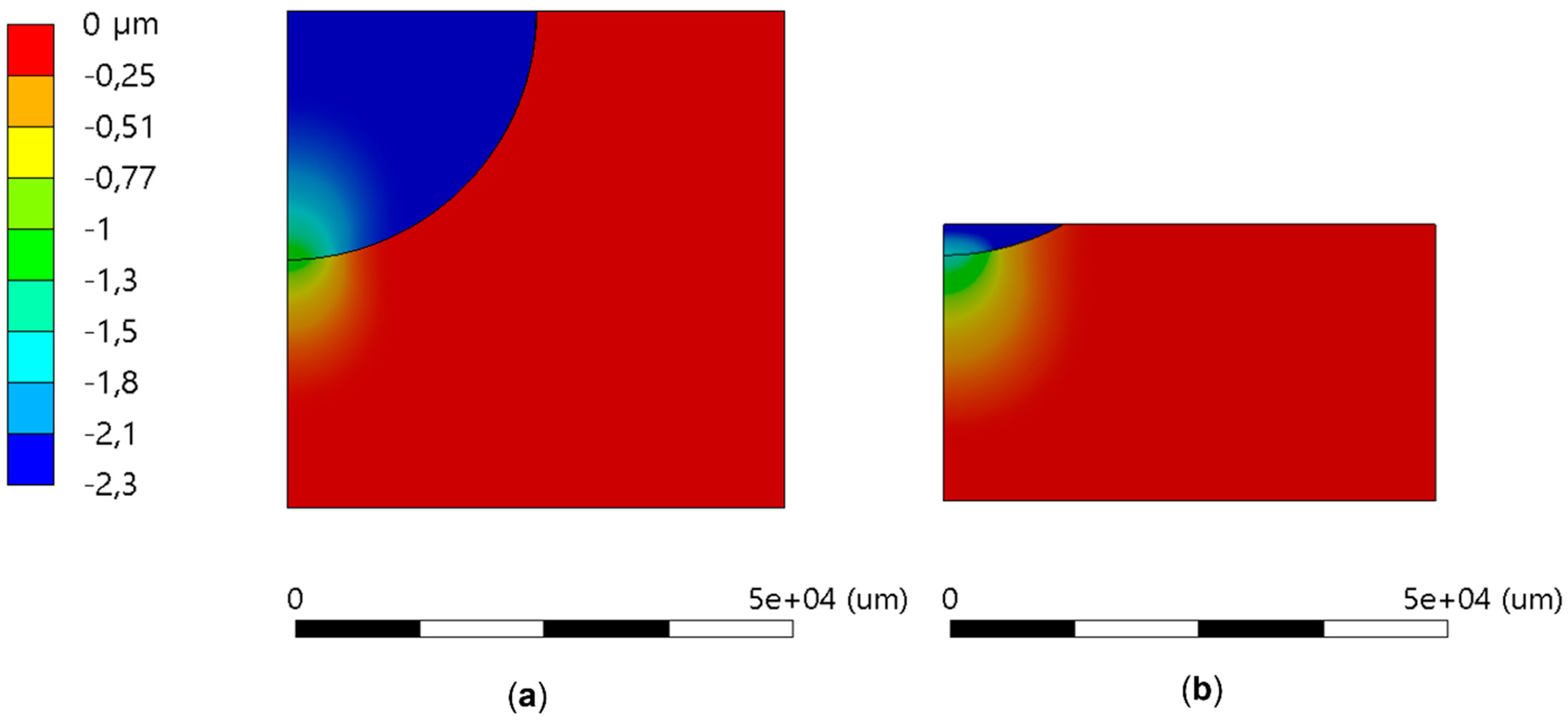
The significant effect of body dimensions in conformal contacts is due to the fact that the contact area is no longer negligible and the contact pressure influence zone is no longer confined in a small volume as shown in the displacement map of
Figure 11. The displacement maps of two different cases of cap and seat heights for the same imposed displacement at the cap upper surface are presented in
Figure 15. The differences are remarkable.
Further simulations investigated the effect of friction on the lowest clearance example (C = 0.05%), and the seat boundary conditions. Two different boundary conditions were tested on the seat, namely frictionless support and fixed. The smaller the seat, the larger the effect of the boundary conditions on its mechanical behavior. Thus, only the case with the smallest investigated seat (
b/R = 0.125) is reported here (
Figure 16). However, even in this case, the difference is minor.
Usually for lubricated steel on steel, a friction coefficient
f = 0.15 can be assumed; for dry steel on steel, a friction coefficient
f of about 0.5 can be assumed.
Figure 17 shows the results for relatively high friction coefficient
f = 0.8 in the conformal contact pair for the lowest clearance (
C = 0.05%)
Figure 17 shows that the simulation with friction diverges more from the theoretical curve. However, in practical applications, the contact pair is usually lubricated, thus reducing this effect considerably.
6. Conclusions
In this paper the applicability of the Hertzian formulas to the point contact of spheres and caps was investigated. Firstly, the basic assumptions and formulas were recalled as well as previous experimental results that motivated the study.
Then FE calculations, carried out on non-conformal and conformal spherical bodies in contact, allowed for the investigation on different parameters: different geometry, load, materials, and boundaries. The FE results were compared with the results of the formulas showing more or less marked differences in deformations, depending on the considered case. The main conclusions can be summarized as follows:
The results regarding the relative displacement of non-conformal spherical bodies were in good agreement with the theoretical ones.
Regarding the conformal spherical bodies, the radial clearance and the dimensions of both the cap and the seat showed a great influence on their non-Hertzian behavior. The differences in relative displacement increased with decreasing geometrical quantities. Moreover, friction, in this case, showed a non-negligible effect.
For all the considered cases, Hertz’s formula always provided the greatest rigid body approach which means the lowest contact stiffness.
The reported investigation is intended as the first step of a research activity aimed at the development of analytical formulas to be tuned by FE simulation or experimental testing to better replicate the behavior of conformal contacts. Experimental testing, limited up to now to few samples, will be extended to a larger and more-varied population, and the effects of other important (but little-explored) characteristics, such as roughness, will be investigated.


