Abstract
Three-phase induction motors (IMs) are the main workhorse in industry due to their many advantages as compared to other types of industrial motors. However, the efficiency and lifetime of IMs can be considerably affected by some operating conditions, in particular those related to unbalanced supply voltages (USV), which is quite a common condition in industrial plants. Therefore, early detection and a precise severity estimation of the USV for all working conditions can prevent major breakdowns and increase reliability and safety of industrial facilities. This paper proposes a reliable method allowing for a precise and online detection of the USV condition, by monitoring a pertinent indicator calculated using the voltage symmetrical components. The effectiveness of the proposed method is validated experimentally for several different working conditions, and a comparison with other indicators available in the literature is also performed.
1. Introduction
Nowadays, more than 85% of electric motors used in industry are three-phase induction motors (IMs) [1,2,3,4]. They are widely used due to their reliability, convenience of design, high performance, and overloaded capacity, for different applications such as manufacturing, processing, power systems, transportation, etc. However, IMs are usually working under severe mechanical and electrical operating conditions that make them vulnerable to numerous stators and/or rotor faults. Furthermore, unbalanced supply voltages (USV), which is a quite common electrical problem in industrial plants, can seriously affect the IMs more than any other electrical equipment. Indeed, even if the USV is small, large, unbalanced currents flow due to the relatively small negative sequence impedance. These large currents lead to diverse heating problems that cause more losses, vibrations, acoustic noises, and decrease in torque, which can eventually shorten the lifespan of the IMs. Due to the various damages that an USV can produce in IMs, different standards have defined the maximum limits allowed for this phenomenon, including NEMA [5], IEEE, and IEC standards each one with different considerations [6,7,8]. The occurrence of USV in an industrial power system is due to a multiplicity of causes, the most common are [9]: faulty operation of power factor correction equipment, unequally distributed single-phase loads on the same power system, and an open-circuit on the primary distribution system. The study of USV was the topic of many research papers, where their main subject was the study of the USV’s causes and its effects on the electrical machines in order to determine its permissible levels. For instance, the first factor dedicated to quantifying either the voltage or current unbalances was proposed by Fortescue in [10]. This factor was defined as the ratio of negative and positive components. After that, many other factors were proposed to measure the USV; the more relevant are: the voltage unbalance factor (VUF) adopted by IEC standard [11], the percent voltage unbalance (PVU) defined by NEMA standard [5] and the complex voltage unbalance factor (CVUF) [12,13,14]. The PVU is defined as the maximum deviation of the RMS line voltage from the average of the three RMS line voltages. It is a convenient factor to be used in field measurements since its calculation includes just the RMS or the magnitudes of the three-phase voltages. However, the VUF and CVUF are calculated as the ratio of the line voltage positive and negative sequences. Their computation requires both the magnitudes and phases of the three-phase voltages, which is quite difficult in practice. On the other hand, the VUF provides better physical interpretation of the cause of voltage unbalance, and it is more useful in the prediction and analysis of the USV effects on electrical machines. A deep literature review shows that most of the published papers were focused on the study of the USV effects on the IMs performance in terms of speed, torque, current losses, power factor, and efficiency [13,15,16,17,18,19]. However, the online detection of the USV is not very much reported. In [20], a method based on the Goertzel algorithm was used to extract some spectral components from the Park’s vector and the motor vibration to detect an incipient USV. In [21], a technique called symbolic dynamic filtering (SDF) was proposed for the early detection of stator voltage unbalance in three-phase induction motors. The algorithm involves wavelet transform of stator current signals and subsequent analysis based on D-Markov machine construction. In [22], it was demonstrated that supplying an IM with unbalanced voltages generates mechanical vibrations. Thus, an ILFE fiber-optic sensor was proposed and designed to detect these vibrations in the range DC-500 Hz. The authors of [22] stated that the obtained signal can be considered as a good USV indicator. A protection model based on the thermal impact analysis of voltage unbalance is developed in [23] with the aim of protecting the motor against USV problems.
Therefore, one of the aims of this paper is to fill this gap by proposing a low-cost implementation algorithm that can be used online in order to detect and quantify, at an incipient stage of development, any level of unbalance in the voltages supplying an IM. In this paper, the idea of network decomposition [1] is used. But instead of providing different representations for three, two- and single-phase equipment, Fortescue coordinates are applied for all calculated unbalanced networks. On the other hand, a modified version of Prony’s method is proposed for IMs unbalanced voltage fault detection, by estimating and tracking the symmetrical components’ characteristic frequency and its corresponding amplitude, from the stator current and voltage signals [24,25]. The proposed technique can provide a linear time–frequency and amplitude representation of the fault characteristic component with high-frequency resolution and adjustable time resolution. The proposed method is demonstrated to be robust and independent of load variations or the occurrence of any other motor faults. The paper contains three main sections. The second part describes the STLSP technique that was used to extract and monitor the amplitude of the most significant harmonics associated with an unbalanced voltage supply condition. The third section reports on the experimental results for both healthy and defective conditions, as well as the validation of a real-time diagnostic technique for detecting unbalanced supply voltages in induction motors. In addition, a comparative study is carried out based on four criteria: sensitivity to low USV occurrence, sensitivity to the severity of the USV, robustness to load variations, and robustness to other comparable faults. The final part of the paper is dedicated to the general conclusions.
2. The Proposed USV Detection Method
The aim here is to obtain a reliable and quantifiable indicator allowing for an online and fast detection of USV, and that leads to a rapid action in order to protect three-phase induction motors. The proposed idea is inspired in the study of the voltage unbalance in the power network analysis. Indeed, the Voltage Unbalance Factor (VUF) is defined as the ratio between the negative and positive symmetrical components of voltages [1,2]. Since it is obtained starting from the negative sequence, let us call it negative voltage unbalance factor (NVF):
The voltage symmetrical components are calculated using the well-known Fortescue transform (FT). Therefore, the application of the FT on three-phase unbalanced supply voltages (Va, Vb, Vc) of an induction motor leads to three symmetrical components: positive (V+ or Direct), negative (V− or Inverse) and zero (Vo or Homopolar). These symmetrical components can be obtained as expressed in the following matrix form:
where: ,
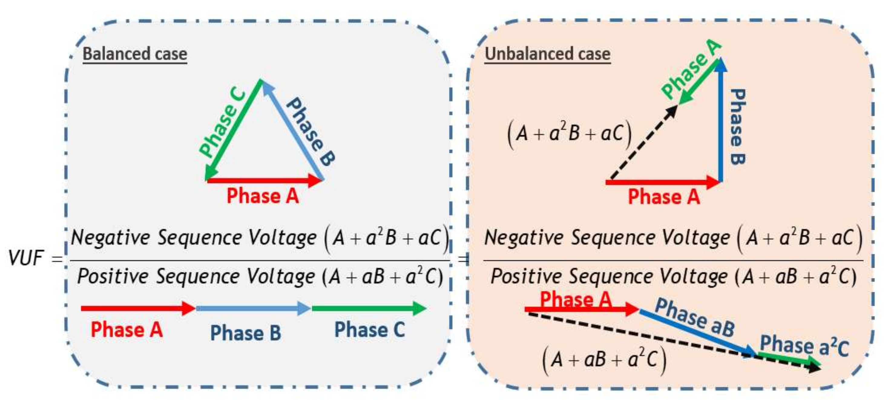
For balanced supply voltages, only the positive symmetrical component exists, the other components (negative and zero) remain null. However, when USV occurs, the negative symmetrical components appear. Thus, the level of USV can be evaluated using the factor VUF defined in (1). Furthermore, Figure 1 shows a graphical representation of VUF in both balanced and unbalanced cases [26]. The numerator of the under-balanced VUF definition in Equation (1) becomes almost zero. In another sense, the component of the negative-sequence phase is an indication of the unbalance rate. When at least one phase or magnitude of voltage is out of balance, then an unbalance occurs, and because the line impedance is kept balanced, the voltage imbalance is caused by the current (power) imbalance. Because it is nearly impossible for the positive sequence voltage to become zero, the voltage produces an imbalance if the negative sequence voltage is not zero.
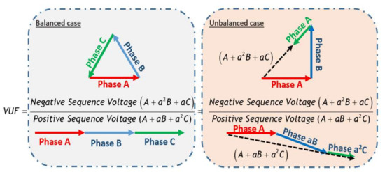
Figure 1.
A graphical interpretation of VUF for balanced and unbalanced cases.
As stated before, the occurrence of USV in induction motors produces an unbalance in the line currents which is reflected also by an unbalance in the stator winding impedances. For that reason, the proposed idea consists of computing the symmetrical components related to the line stator currents and the stator winding impedances. Consequently, it is possible to define the negative current factor (NCF) and the negative impedance factor (NIF) as follows:
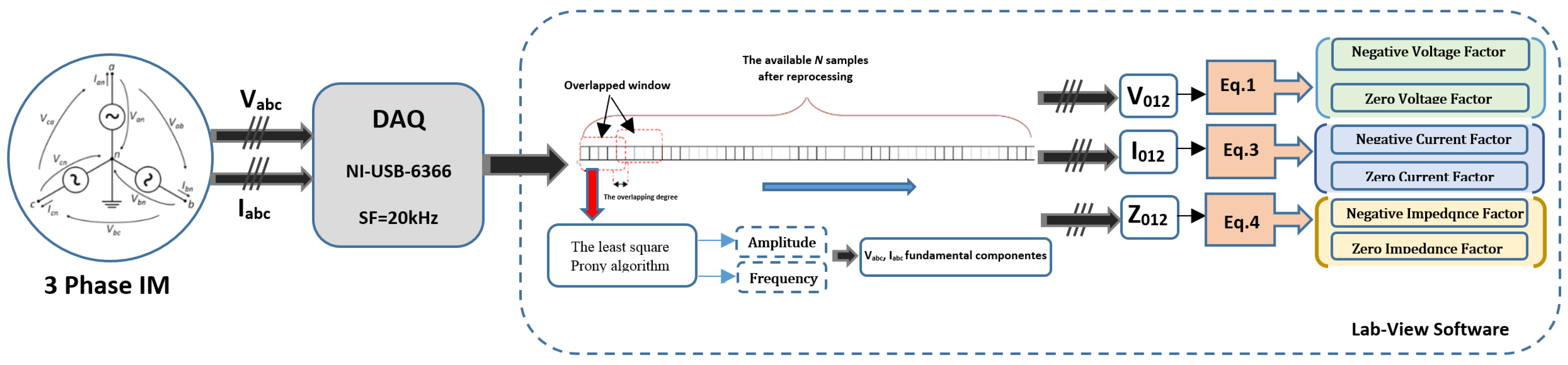
The key point of the proposed idea is to estimate and track only the fundamental harmonics related to the voltages and currents to compute the required symmetrical components, which will be then used to calculate the different factors. Therefore, the proposed method can be described by the following steps (Figure 2):
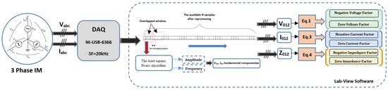
Figure 2.
Illustrative scheme of the online implementation of the proposed technique.
Step 01: Acquisition of the three-phase currents and voltages ;
Step 02: Extraction of the fundamental harmonics (magnitudes and phase angles) related to the three-phase voltages and currents . This can be performed thanks to the short time least square Prony’s (STLSP) method which is a high-resolution signal processing technique that has the ability to estimate and track accurately all the attributes (frequency, amplitude, phase, and damping factor) of any harmonics from a short data record signal. This allows the consideration of the non-stationary aspect of the problem [24]. To reduce the impact of some influential features, and thus obtaining improved results, a preprocessing of the acquired signals is necessary. In fact, data acquisition parameters, filtering, DC components removal, and dawn sampling are the main involved tasks [24,25].
(a) Firstly, using the available data samples, the Prony method constructs an homogenous linear difference equation with constant coefficients (with a0 = 1). Then, the unknown parameters ak that fit the observed data are selected to minimize the linear prediction total squared error. This can be done by using the least square method.
(b) The obtained parameters ak are used to form a characteristic polynomial with roots zk:
(c) The obtained roots zk are used to write the N equations of the model:
(d) Finally, from steps (b) and (c), it will be possible to deduce the amplitude, frequency, phase angle, and damping factor using the following expressions:
Step 03: Calculation of the symmetrical components related to the supply voltages and stator currents ().
Step 04: Calculation of the symmetrical components related the stator winding impedances:
Step 05: Generation of the three-unbalance factors NVF, NCF, and NIF using Equations (1), (3), and (4), respectively.
3. Experimental Validation
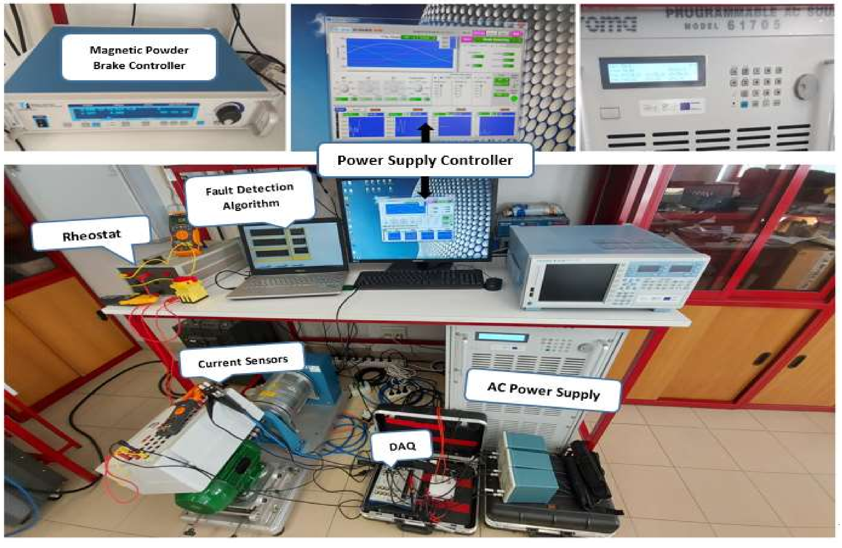
In this section, the bahvior of each unbalance factor will be analyzed under USV, alongside the different working conditions. The aim is to test and compare between these factors in order to select the best one that allows a reliable detection of the USV. The comparative study is evaluated under different machine operating conditions. The experimental setup used for this goal consists mainly of a three-phase 400 V-50 Hz power supply, and a four pole Y-connected squirrel-cage induction motor (Table 1). Current transducers (hall-effect), a data acquisition system and a remote station for producing voltage unbalance was also used (Figure 3).

Table 1.
Induction motor technical parameters.
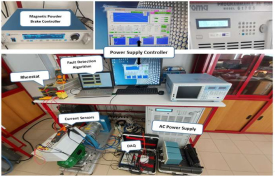
Figure 3.
Experimental setup.
In order to implement the proposed method online, the algorithm used for generating the three unbalance factors was first developed using Matlab code, and then it was inserted into the Lab-VIEW software via the Matlab script mode. The other steps of the proposed method, such as filtering, down-sampling, and offset removing, were performed directly using Lab-VIEW palettes. The IM voltage and current signal measurements were performed through the use of Tektronix P5200A differential voltage probes and Tektronix TCPA300 amplifier + Tektronix TCP312 current probes, and the corresponding signals were acquired through the use of a NI USB-6366 series data acquisition card with a sampling frequency of 20 kHz. These steps were carried out continuously, which permits to follow, in real time, the evolution of the target indicators as well as the different motor quantities such as: voltages, currents, impedances, and the symmetrical components.
The comparative study is performed based on four criteria: sensitivity to the occurrence of low USV, sensitivity to the USV’s severity, robustness against load variations, and robustness against other similar faults.
3.1. Sensitivity to the Occurrence of Low USV
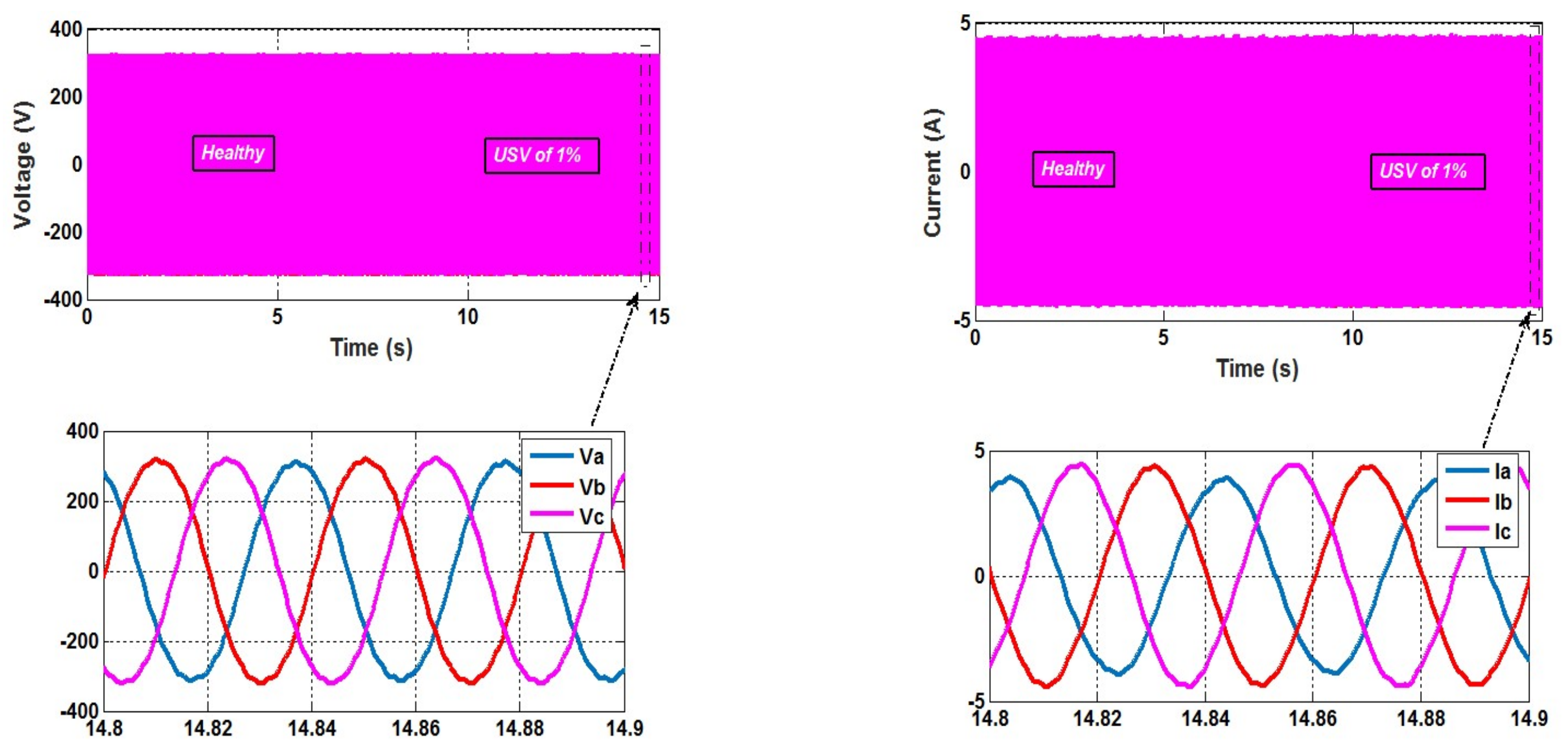
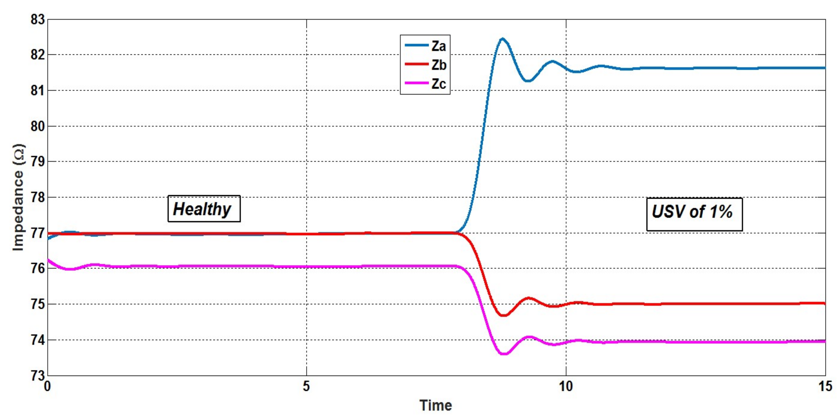
The induction motor was initially supplied with balanced voltages and after 1s, a very low voltage unbalance of 1% is introduced using a programmable power supply. Figure 4 shows the time evolution of the three-phase voltages and currents when a USV of 1% was introduced suddenly in one phase. Obviously, the effects of the unbalanced condition cannot be observed clearly. However, and thanks to the implemented algorithm, the three-phase impedances are online estimated and visualized (Figure 5). It has to be noticed that these impedances are calculated starting from the fundamental harmonics of the three-phase stator voltages and currents. As can be clearly seen, the curves depicted in Figure 5 provide a good physical interpretation of the USV’s effect on the stator winding impedances.
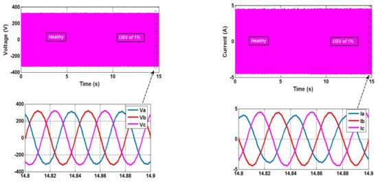
Figure 4.
IM currents and voltages time waveforms for a small USV (1%) at no load.
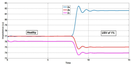
Figure 5.
IM estimated Za,b,c for a small USV (1%) at no load.
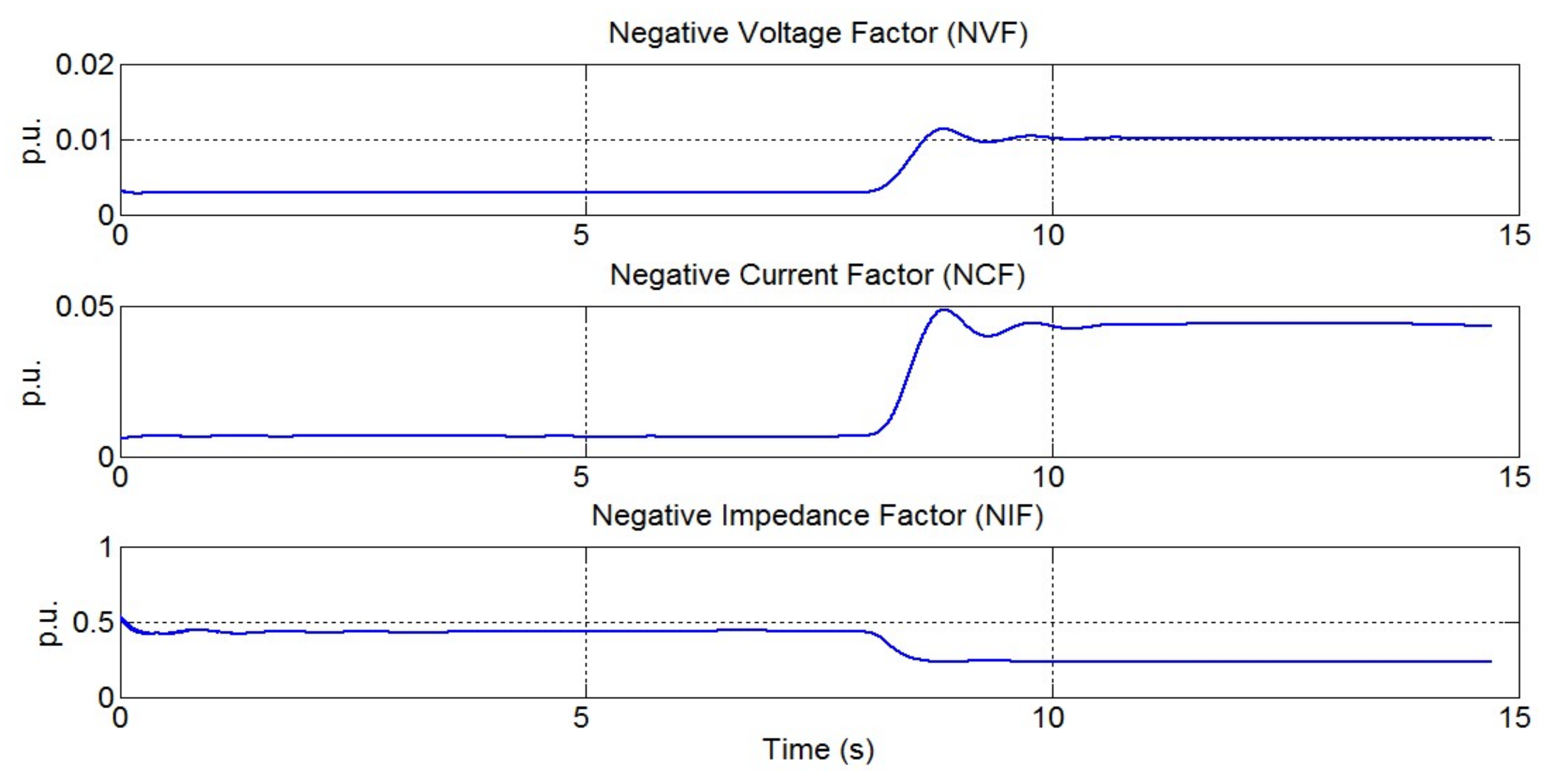
Figure 6 illustrates the time evolution of the three factors NVF, NCF, and NIF, while Table 2 shows the magnitudes of these factors and the rate of their changes after the USV occurrence. As can be clearly seen, the three factors present stable values when the motor operates under balanced voltages, but after the occurrence of a low severity USV (1%), a significant increase of 252% and 576% is observed on NVF and NCF, respectively. Meanwhile, the NIF was decreased by 47%. These results confirm that the presence of USV produces three voltage symmetrical sequences, of which the most damaging is the negative one. Therefore, a small negative sequence of voltage causes a large negative sequence of currents, resulting in large currents unbalance. This explains why the NCF has increased more than the NVF.
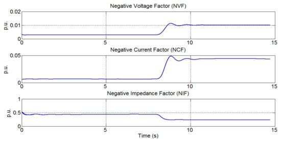
Figure 6.
The estimated unbalance factors with an USV of 1.45%.
Table 2.
Effect of the USV on the defined unbalance factors.
These qualitative and quantitative results demonstrate, on the one hand, the implementation success of the proposed algorithm and, on the other hand, they show the superiority of both NCF and NVF as compared to the NIF in terms of sensitivity to the occurrence of a low severity USV.
3.2. Sensitivity to the USV’s Severity
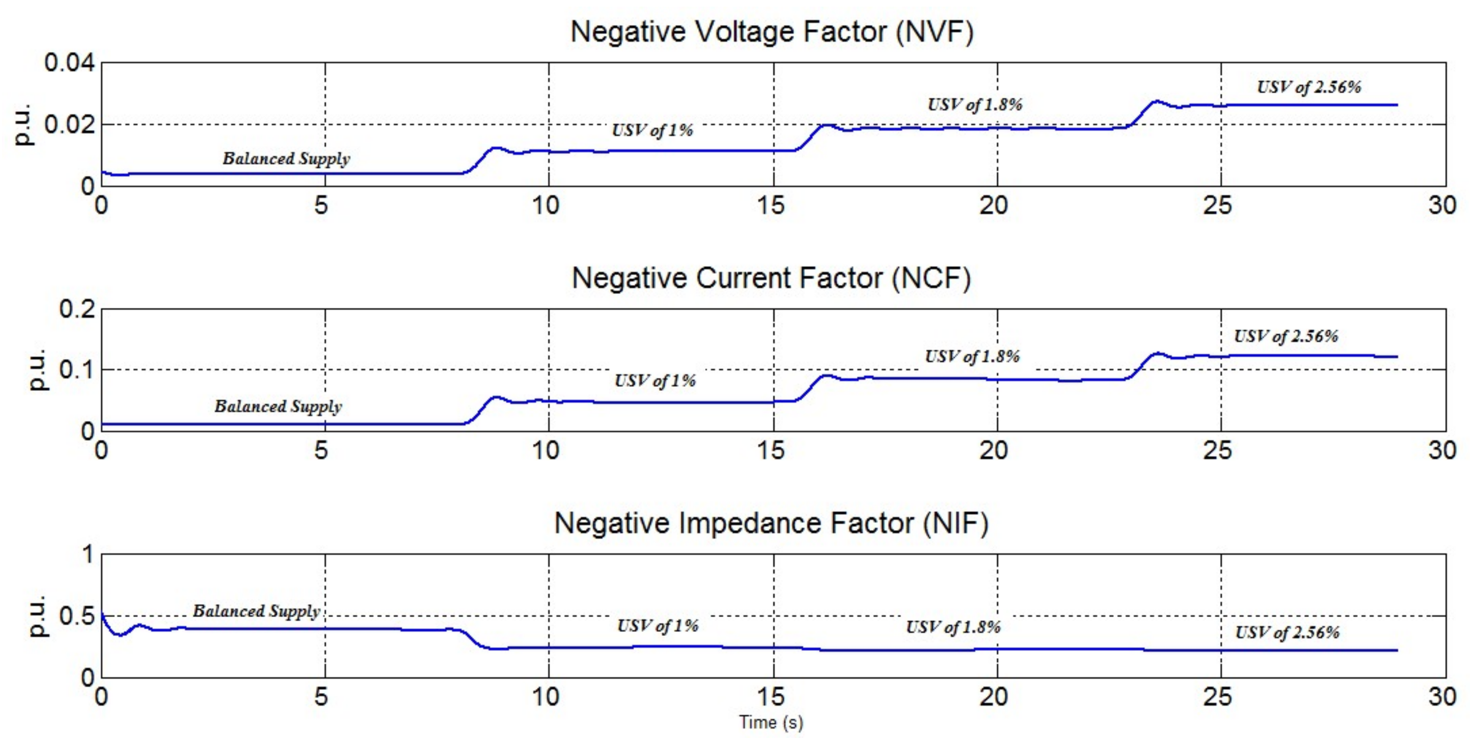
In this section, several tests are carried out in order to study the behavior of the three factors under successive increases on the USV’s severity. First, the test was started with a motor under balanced supply at no load. After a few seconds and using a programmable power supply, three different levels of USV (1%, 1.8%, and 2.56%) according to NEMA definition, were introduced successively. The curves depicted in Figure 7 show clearly that the proposed algorithm has the ability to compute and track successfully the time evolution of the studied factors.
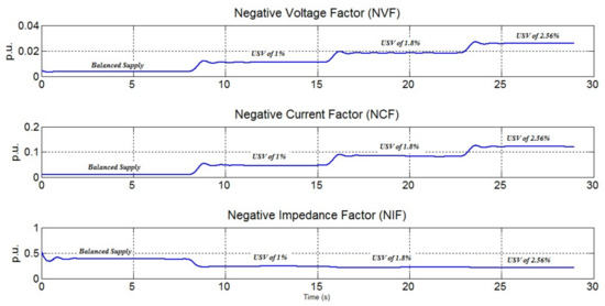
Figure 7.
Time evolution of the defined factors for different USV’s levels at no load.
In addition, Table 3 illustrates quantitatively the changes (in percentage) observed on these factors after each increase on the USV’s severity. It can be noticed that NIF is almost insensitive to the USV occurrence, and thus it cannot be considered as a reliable indicator for the unbalance voltage problems. However, both NVF and NCF rise significantly as a function of the USV severity, but NCF looks to be even more sensitive, as illustrated in Table 3.
Table 3.
Values of the three factors for different USV’s levels.
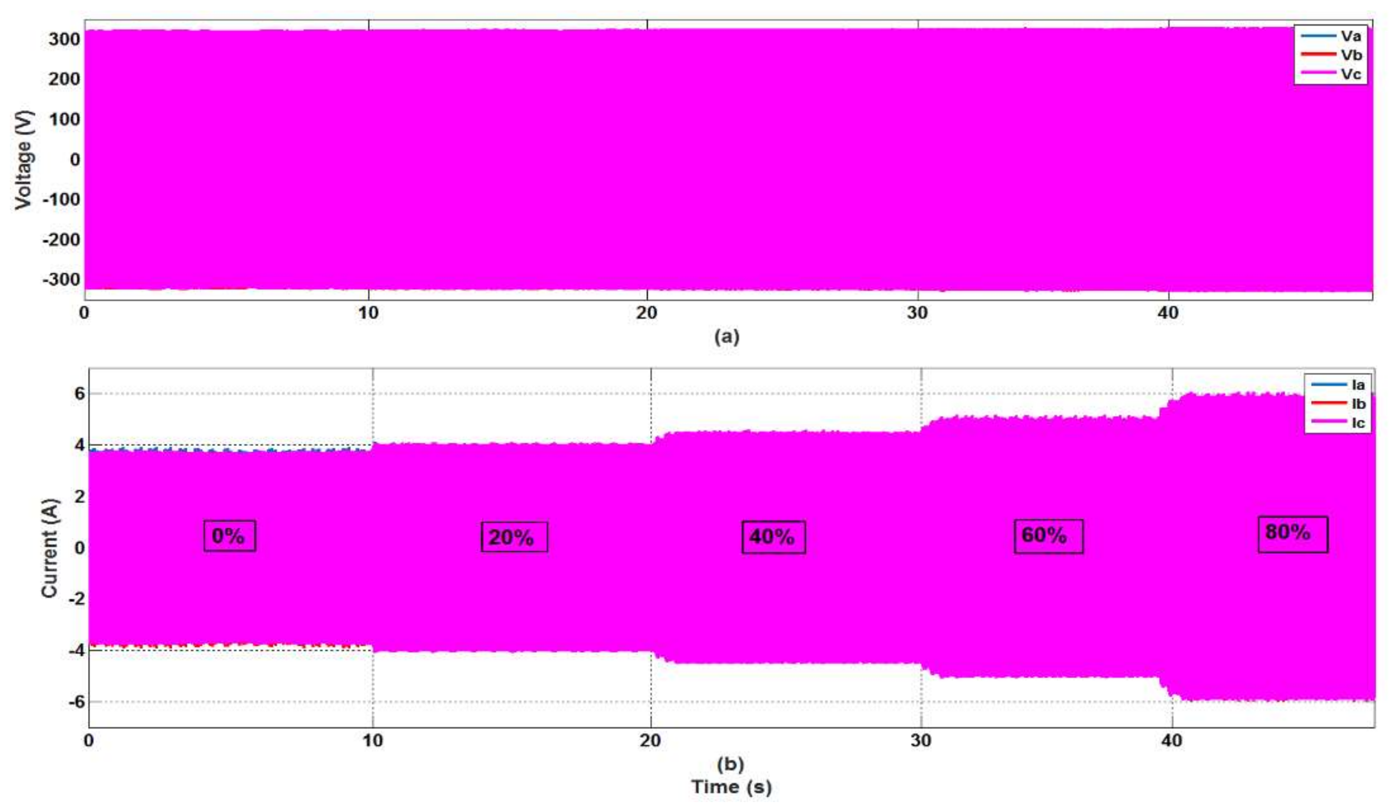
3.3. Robustness against Load Variations
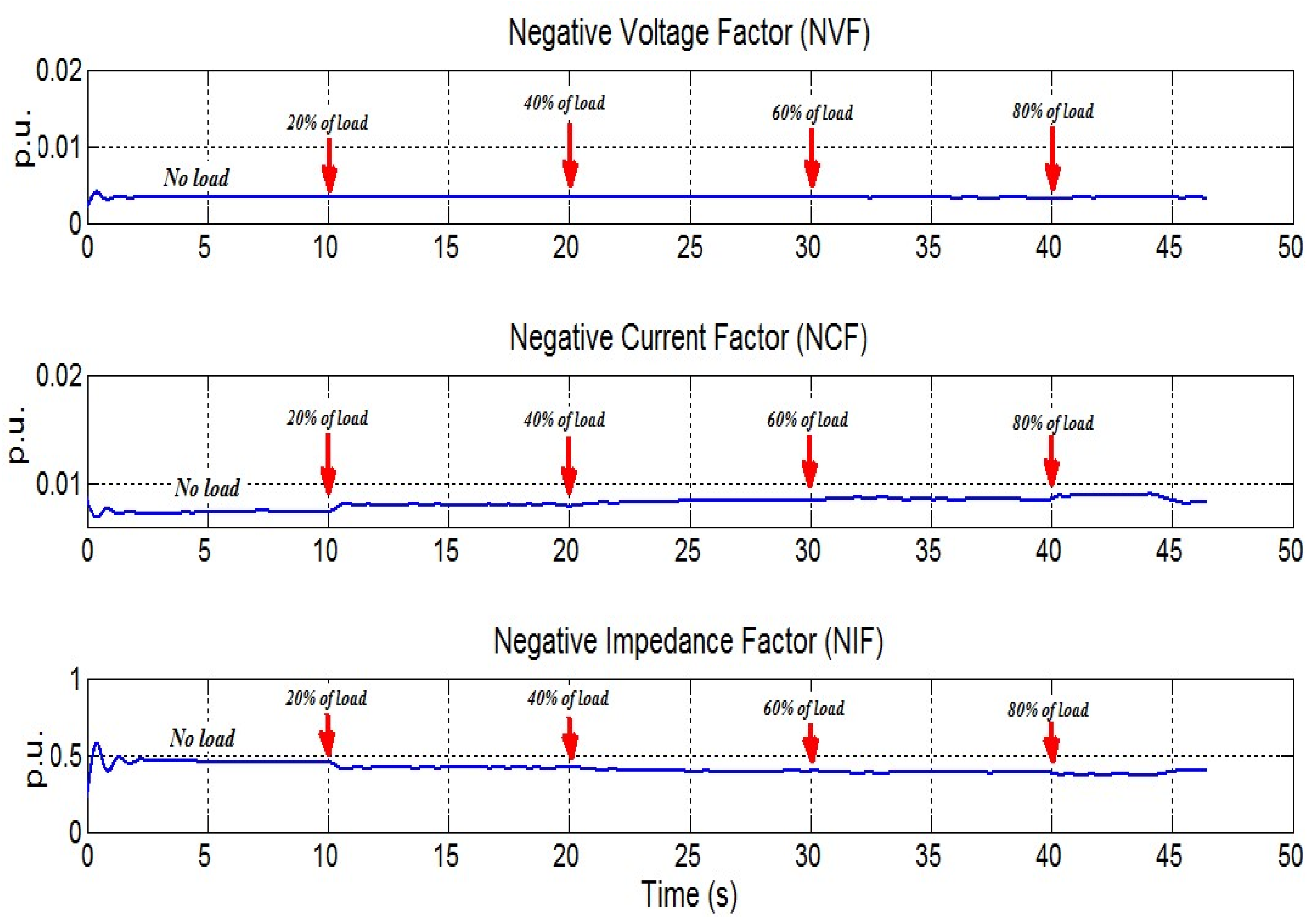
The previous tests were performed with constant mechanical load. But in practice, the motor load can change gradually or by step variations at any time, which can affect directly the motor currents and consequently the fault indicators used by the condition monitoring systems. Thus, a reliable fault indicator must prove its insensitivity to the load changes. For that reason, several experimental tests were performed in order to study the behavior of the defined factors when a series of step load variations are applied suddenly. Figure 8 shows that the application of step load variations has an important influence on the time waveforms of the motor currents, thus producing non-stationary signals with high distortion. Fortunately, the implemented algorithm uses the STLSP method which has proved its suitability for such a situation [25] since it requires only a few numbers of samples to compute and track the NVF, NCF, and NIF. The curves representing the time evolution of these factors are depicted in Figure 9. As it can be clearly seen, the changes on the motor load have no effect on all of the three factors, which confirm their robustness against load variations.
Figure 8.
IM voltage and current waveforms for a balanced supply condition, under different step load variations.
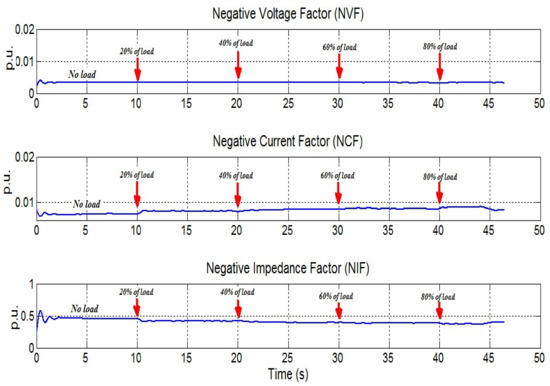
Figure 9.
The studied factors for a balanced supply condition, under different step load variations.
3.4. Robustness against Similar Faults
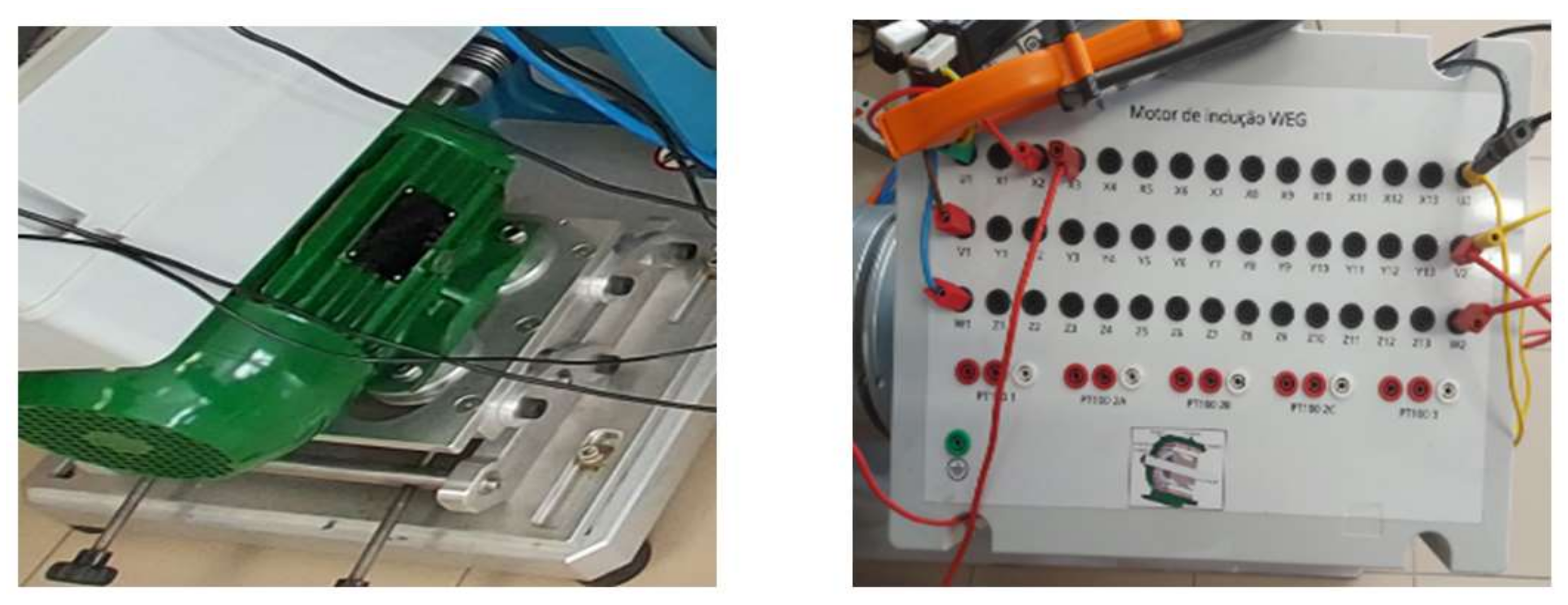
The reliability of any fault indicator must also be measured by its robustness against the occurrence of other faults having similar symptoms. Indeed, the occurrence of inter-turn short-circuit faults (ITSCF) in induction motors produces a kind of unbalance on the supply voltages, stator currents, and the stator winding impedances. As a result, this fault produces effects similar to those produced by the USV. Therefore, it is important to study the behavior of NVF and NCF under the occurrence of ITSCF. For that reason, the stator winding of the used IM was modified by adding some tapings connected to the stator coils. The other ends of these external wires are connected to the motor terminal box and, therefore, allowing for the creation of ITSCF with different numbers of shorted turns (Figure 10).
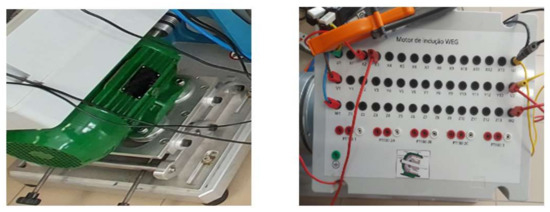
Figure 10.
Induction motor used for the ITSCF tests.
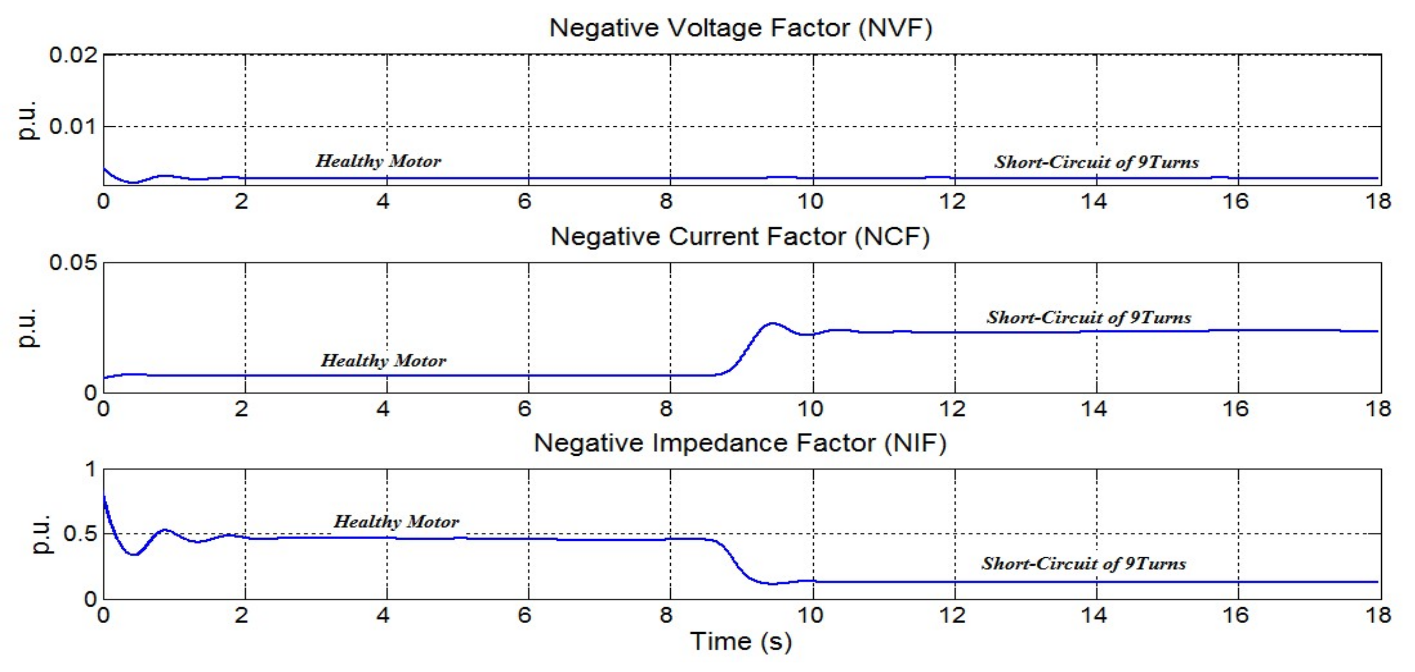
First, the motor was initially started at no load under healthy state conditions, and after a few seconds, nine turns of the phase “a” were short-circuited. During this operation, the three-phase currents and voltages were sampled and online treated by the proposed algorithm. The curves representing the time evolution of the studied factors are depicted in Figure 11, while Table 4 shows their rate of change due to this winding fault. As can be clearly seen, the NCF which was more sensitive to the USV is also sensitive to the ITSCF. Indeed, the NCF has increased considerably by 255% after the short-circuit of 9 turns. Consequently, the NCF cannot be considered as USV indicator because it behaves similarly for both ITSCF and USV, which can lead to a misdiagnostic.
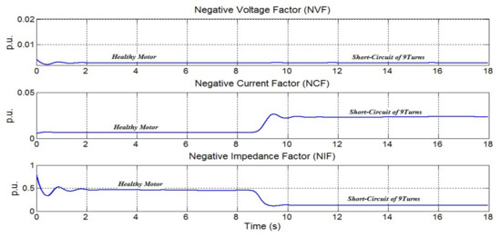
Figure 11.
The defined factors for both healthy conditions and nine turns in short-circuit.
Table 4.
Effect of the ITSCF on the defined unbalance factors.
The NIF has decreased by 71% due to the ITSCF, and the same reaction was observed in the case of USV occurrence. However, the NVF which was sensitive to the USV is now completely insensitive to the ITSCF. These results prove the superiority of the NVF compared to both NCF and NIF.
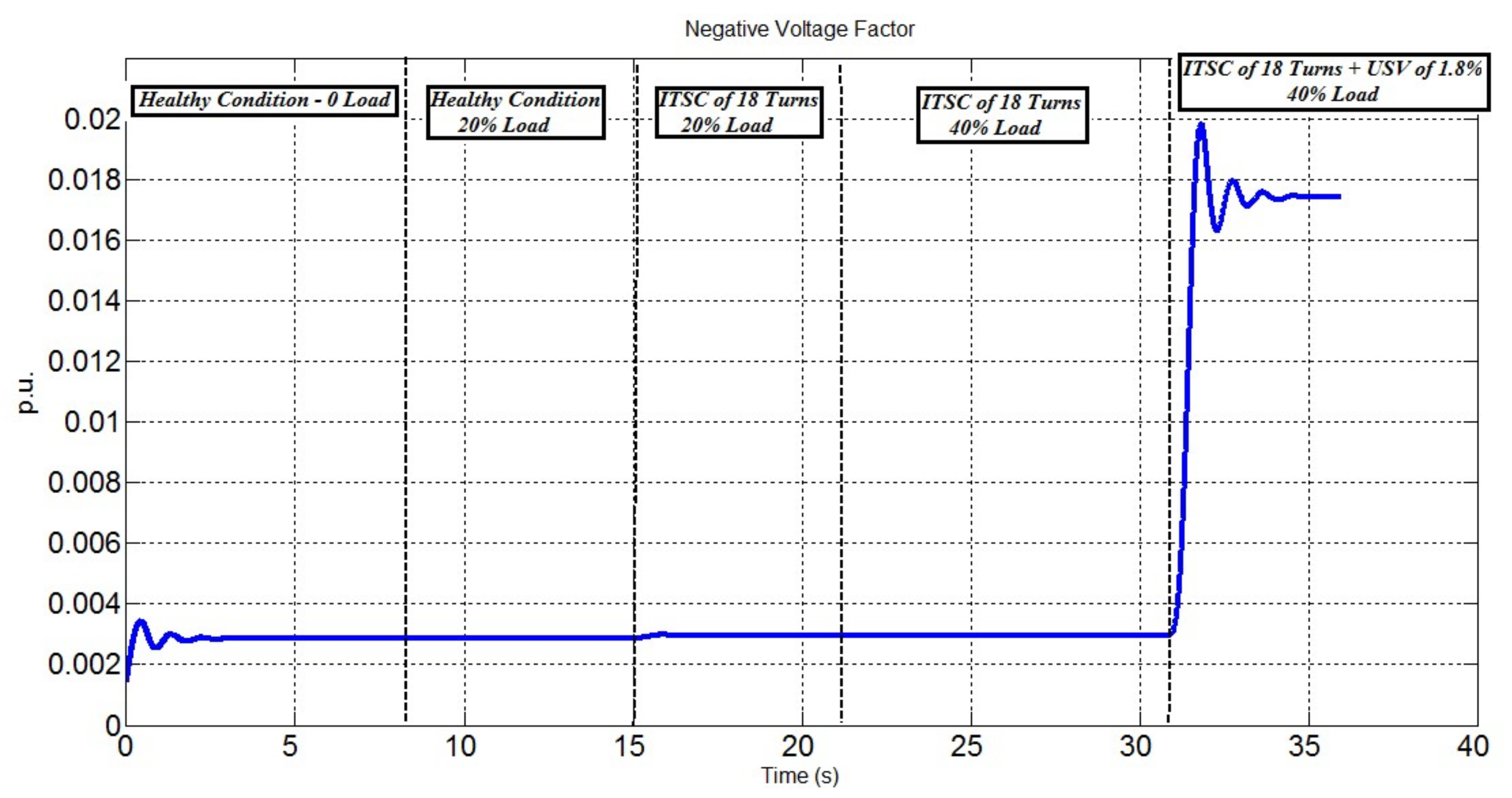
In order to confirm the effectiveness of the NVF in terms of the reliability of the detection of an incipient USV under even more complicated operating conditions, five successive experimental scenarios were considered:
- (1)
- Start the motor in a healthy state, with balanced supply voltages, at no load;
- (2)
- Increase the motor load by 20% (the motor always in healthy state);
- (3)
- Introduce an ITSCF of 18 turns in the phase “a”, under 20% of load, with balanced supply voltages;
- (4)
- Increase the motor load to 40% (the motor remains with ITSCF and balanced supply voltages);
- (5)
- Introduce an USV of 1.8% in the presence of ITSCF.
During these tests only the three-phase voltages are sampled and treated by the proposed algorithm. This permits an online calculation and a continuous displaying of the NVF as shown in Figure 12. As can be clearly seen, the NVF remains almost constant through the first four tests, and then it increases rapidly and significantly just after the occurrence of the USV. This confirms that the NVF is the best indicator for the USV problems in terms of reliability and sensitivity of detection, robustness against load variations or ITSCF, as well as to its simplicity of calculation since it requires only the acquisition of the three-phase voltages which are always available. As a result, the condition monitoring systems based on the NVF are easy to be implemented experimentally and can work successfully in real time.
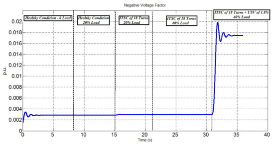
Figure 12.
Time evolution of the NVF under different operating conditions.
Hence, it is believed that the proposed method would also be suitable for other types of electric motors (e.g., multi-phase induction machines, permanent-magnet machines, and reluctance machines); ongoing research efforts are focused on these subjects.
4. Conclusions
In this paper, an online algorithm based on the STLSP method was proposed in order to generate a pertinent indicator that allows a rapid and a reliable detection of an incipient USV for the applications that use induction motors. To achieve this aim, three potential indicators (NVF, NCF and NIF) were considered. To select the best one, an experimental comparative study was performed based on four criteria: sensitivity to the occurrence of low USV, sensitivity to the USV’s severity, robustness against load variations, and robustness against other similar faults. The proposed algorithm was successfully implemented under the LabVIEW environment. Furthermore, its capabilities for the online calculation and the continuous displaying of the different indicators was effectively demonstrated. Several experimental tests and different scenarios under various operating conditions were carried out on a 2.2 kW induction motor. The obtained results show that neither load variations nor ITSCF occurrence have any significant effect on the NVF. Indeed, it was demonstrated that NVF is only sensitive to the USV problems, which prove its effectiveness and superiority compared to the other indicators (NCF and NIF).
Author Contributions
Conceptualization, K.L., M.S., A.A. and A.J.M.C.; methodology, K.L., M.S. and A.J.M.C.; software, K.L., M.S. and A.A.; validation, K.L., M.S. and A.A.; formal analysis, K.L., M.S. and A.A.; investigation, K.L.; resources, A.J.M.C.; data curation, K.L. and M.S.; writing—original draft preparation, K.L. and M.S.; writing—review and editing, A.J.M.C.; visualization, K.L. and M.S.; supervision, A.J.M.C.; project administration, A.J.M.C.; funding acquisition, A.J.M.C. All authors have read and agreed to the published version of the manuscript.
Funding
This work was supported by the European Regional Development Fund (ERDF) through the Operational Programme for Competitiveness and Internationalization (COMPETE 2020), under Project POCI-01-0145-FEDER-029494, and by National Funds through the FCT—Portuguese Foundation for Science and Technology, under Projects PTDC/EEI-EEE/29494/2017, UIDB/04131/2020, and UIDP/04131/2020.
Data Availability Statement
Not applicable.
Conflicts of Interest
The authors declare no conflict of interest.
References
- Cummings, P.B.; Dunki-Jacobs, J.R.; Kerr, R.H. Protection of induction motors against unbalanced voltage operation. IEEE Trans. Ind. Appl. 1985, IA-21, 778–792. [Google Scholar] [CrossRef]
- Bento, F.J.F.; Adouni, A.; Muxiri, A.C.P.; Fonseca, D.S.B.; Cardoso, A.J.M. On the Risk of Failure to Prevent Induction Motors Permanent Damage, Due to the Short Available Time-to-Diagnosis of Inter-Turn Short-Circuit Faults. IET Electr. Power Appl. 2021, 15, 51–62. [Google Scholar] [CrossRef]
- Adouni, A.; Marques Cardoso, J.A. Thermal Analysis of Low-Power Three-Phase Induction Motors Operating under Voltage Unbalance and Inter-Turn Short Circuit Faults. Machines 2021, 9, 2. [Google Scholar] [CrossRef]
- Kurt, M.S.; Balci, M.E.; Aleem, S.H.E.A. Algorithm for estimating derating of induction motors supplied with under/over unbalanced voltages using response surface methodology. J. Eng. 2017, 2017, 627–633. [Google Scholar] [CrossRef]
- Motors and Generators, NEMA MG1. 2014. Available online: https://www.techstreet.com/standards/nema-mg-1-2014?product_id=1888468 (accessed on 23 August 2021).
- Smith, J.C.; Hensley, G.; Ray, L. 1159-1995-IEEE Recommended Practice for Monitoring Electric Power Quality; IEEE: New York, NY, USA, 1995; Available online: https://ieeexplore.ieee.org/document/8796486 (accessed on 23 August 2021).
- IEEE Standard. IEEE Recommended Practice for Monitoring Electric Power Quality; IEEE Std, ICS Code: 29.240.01—Power Transmission and Distribution Networks in General; IEEE Standard: New York, NY, USA, 2012; pp. 1159–2009. [Google Scholar]
- Machines—Part Rotating Electrical. 26: Effects of Unbalanced Voltages on the Performance of Three-Phase Induction Motors. IEC 2002, 60, 26–34.
- Lashkari, N.; Poshtan, J.; Azgomi, H.F. Simulative and experimental investigation on stator winding turn and unbalanced supply voltage fault diagnosis in induction motors using artificial neural networks. ISA Trans. 2015, 59, 334–342. [Google Scholar] [CrossRef] [PubMed]
- Fortescue, C.L. Method of symmetrical co-ordinates applied to the solution of polyphase networks. Trans. Am. Inst. Electr. Eng. 1918, 37, 1027–1140. [Google Scholar] [CrossRef]
- IEC 60034-1. Rotating Electrical Machines Part 1: Rating and Performance; International Electrotechnical Commission (IEC): Geneva, Switzerland, 2004. [Google Scholar]
- Wang, Y.J. Analysis of effects of three-phase voltage unbalance on induction motors with emphasis on the angle of the complex voltage unbalance factor. IEEE Trans. Energy Convers. 2001, 16, 270–275. [Google Scholar] [CrossRef]
- Faiz, J.; Ebrahimpour, H.; Pillay, P. Influence of unbalanced voltage on the steady-state performance of a three-phase squirrel-cage induction motor. IEEE Trans. Energy Convers. 2004, 19, 657–662. [Google Scholar] [CrossRef]
- Mantilla, L.F. An analytical and graphical study of the symmetrical components in an induction motor supply in relation to the voltage unbalance parameters. Electr. Eng. 2007, 89, 535–545. [Google Scholar] [CrossRef]
- Anwari, M.; Hiendro, A. New unbalance factor for estimating performance of a three-phase induction motor with under-and overvoltage unbalance. IEEE Trans. Energy Convers. 2010, 25, 619–625. [Google Scholar] [CrossRef]
- Rengifo, J.; Salazar, H.; Bueno, A.; Aller, J.M. Experimental evaluation of the voltage unbalance in the efficiency of induction motors. In Proceedings of the 2017 IEEE Workshop on Power Electronics and Power Quality Applications (PEPQA), Bogota, Colombia, 31 May–2 June 2017; pp. 1–6. [Google Scholar]
- Tabora, J.M.; Tostes, M.E.D.L.; de Matos, E.O.; Bezerra, U.H.; Soares, T.M.; de Albuquerque, B.S. Assessing Voltage Unbalance Conditions in IE2, IE3 and IE4 Classes Induction Motors. IEEE Access 2020, 8, 186725–186739. [Google Scholar] [CrossRef]
- Dekhandji, F.Z.; Refoufi, L.; Bentarzi, H. Quantitative assessment of three phase supply voltage unbalance effects on induction motors. Int. J. Syst. Assur. Eng. Manag. 2017, 8, 393–406. [Google Scholar] [CrossRef]
- Agamloh, E.B.; Peele, S.; Grappe, J. Operation of variable frequency drive motor systems with source voltage unbalance. In Proceedings of the 2017 Annual Pulp, Paper and Forest Industries Technical Conference (PPFIC), Tacoma, WA, USA, 18–23 June 2017; pp. 1–9. [Google Scholar]
- Moussa, M.A.; Maouche, Y.; Louze, L.; Khezzar, A. A practical implementation of online computational tool for unbalanced voltage supply detection in induction motor. In Proceedings of the 2014 IEEE International Conference on Power and Energy (PECon), Kuching, Malaysia, 1–3 December 2014; pp. 93–98. [Google Scholar]
- Samsi, R.; Ray, A.; Mayer, J. Early detection of stator voltage imbalance in three-phase induction motors. Electr. Power Syst. Res. 2009, 79, 239–245. [Google Scholar] [CrossRef]
- Corres, J.M.; Bravo, J.; Arregui, F.J.; Matias, I.R. Unbalance and harmonics detection in induction motors using an optical fiber sensor. IEEE Sens. J. 2006, 6, 605–612. [Google Scholar] [CrossRef]
- Gonzalez-Cordoba, J.L.; Osornio-Rios, R.A.; Granados-Lieberman, D.; Romero-Troncoso, R.D.; Valtierra-Rodriguez, M. Thermal-impact-based protection of induction motors under voltage unbalance conditions. IEEE Trans. Energy Convers. 2018, 334, 1748–1756. [Google Scholar] [CrossRef]
- Sahraoui, M.; Cardoso, A.J.M.; Ghoggal, A. The use of a modified prony method to track the broken rotor bar characteristic frequencies and amplitudes in three-phase induction motors. IEEE Trans. Ind. Appl. 2014, 51, 2136–2147. [Google Scholar] [CrossRef]
- Yahia, K.; Sahraoui, M.; Cardoso, A.J.M.; Ghoggal, A. The use of a modified Prony’s method to detect the airgap-eccentricity occurrence in induction motors. IEEE Trans. Ind. Appl. 2016, 52, 3869–3877. [Google Scholar] [CrossRef]
- Shigenobu, R.; Nakadomari, A.; Hong, Y.-Y.; Mandal, P.; Takahashi, H.; Senjyu, T. Optimization of Voltage Unbalance Compensation by Smart Inverter. Energies 2020, 13, 4623. [Google Scholar] [CrossRef]
Publisher’s Note: MDPI stays neutral with regard to jurisdictional claims in published maps and institutional affiliations. |
© 2021 by the authors. Licensee MDPI, Basel, Switzerland. This article is an open access article distributed under the terms and conditions of the Creative Commons Attribution (CC BY) license (https://creativecommons.org/licenses/by/4.0/).