Article

Investigation on the Finishing Characteristics of a Magnetic Abrasive Finishing Process with Magnetic Abrasive Slurry Circulation System

1
Graduate School of Engineering, Utsunomiya University, 7-1-2 Yoto, Utsunomiya 321-8585, Japan
2
School of Engineering, Course of Mechanical Engineering Systems, Utsunomiya University, 7-1-2 Yoto, Utsunomiya 321-8585, Japan
3
Center for Innovation Support, Utsunomiya University, 7-1-2 Yoto, Utsunomiya 321-8585, Japan
*
Author to whom correspondence should be addressed.
Machines 2021, 9(9), 195; https://doi.org/10.3390/machines9090195
Submission received: 9 August 2021 / Revised: 24 August 2021 / Accepted: 7 September 2021 / Published: 10 September 2021
(This article belongs to the Special Issue Advances of Japanese Machine Design)

Abstract

:
The magnetic abrasive finishing (MAF) process is an ultra-precision surface finishing technology. In order to further improve the finishing efficiency and continuity, a magnetic abrasive finishing process using the circulatory system to renew magnetic abrasive slurry was proposed. This study investigated the mechanism of the compound magnetic finishing fluid in the process using the conveyor belt as the carrier to complete the circulation and finishing through simulation and theoretical analysis. The influence of the different distribution states of the magnetic finishing fluid in the conveyor belt and the finishing area on the finishing characteristics is observed and analyzed, in addition to a series of experiments to explore the feasibility of finishing polychlorotrifluoroethylene resin plate through this process. Experimental results show that as the working gap decreases, the distribution width of compound magnetic finishing fluid on the conveyor belt becomes larger, and the distribution of the points of action on the workpiece in the finishing area is significantly different and the area increases, and obtains a higher finishing force and finishing efficiency. In this study, the surface roughness of polychlorotrifluoroethylene resin plate was improved from 274 nm Ra to 34 nm Ra within 15 min.

1. Introduction

With the development of high-tech industries such as aerospace, die polishing, and semiconductors, smoother surfaces are required. It is difficult to complete advanced engineering materials with high precision and minimal surface defects through traditional grinding and polishing techniques. Recently, the application of a magnetic field during the manufacturing process has attracted attention. Magnetic abrasive finishing (MAF) is one of the advanced finishing processes. In MAF, the necessary finishing force is generated by the magnetic field in the working area, and high surface finish and precision can be achieved [1,2,3,4]. Since the finishing tool (magnetic brush) composed of magnetic particles is flexible and easy to use when closely following the finishing surface, this process is considered to be a promising precision finishing technology [5,6]. In recent decades, many researchers have conducted a series of studies on MAF, and it has been widely used in many fields such as the processing of medical parts and optical parts [7,8,9,10,11]. Shinmura et al. [12,13] introduced the processing principle and finishing characteristics of MAF, and verified the possibility of MAF to achieve precision finishing. Zou et al. [2,14,15,16] proposed a planar MAF process using constant-voltage magnetic brushes and improved the surface uniformity by improving the finishing track. Yin et al. [17,18] developed vibration-assisted MAF to improve finishing efficiency. Jain et al. [19,20]. concluded that the working gap and circumferential speed are parameters that significantly affect the surface roughness value, proving that the force and surface roughness changes increase with the increase of the electromagnet current and the decrease of the working gap. Mulik et al. [21] measured and modeled the normal force and finishing torque under different processing conditions in the ultrasonic-assisted magnetic abrasive finishing process. The mathematical models of normal force and finishing torque established are verified. Yamaguchi et al. [22,23] applied the MAF process to the inner surface finishing of the tube and conducted a series of discussions. The results show that the MAF process has a significant improvement effect on the internal surface quality of the tube. Lee et al. [24,25] combined planetary motion with two-dimensional vibration-assisted magnetic grinding, and proposed a new surface polishing method that enhances the normal force applied to the surface of the workpiece, thereby improving the cutting power and polishing performance of the abrasive. Kala et al. [26,27] studied the finishing force in the dual-disk magnetic abrasive polishing process. The results show that as the machining gap decreases, the normal force and tangential force increase significantly. When the processing speed is too high, the normal force and tangential force will decrease accordingly.
Previous research has studied the influencing factors of the main parameters of MAF process performance, and has made a great contribution to development of MAF. However, for practical applications, there are still some problems. The key problem is that in the traditional MAF process, as the finishing process proceeds, the magnetic brush will be squeezed and worn out. This is not conducive to continuous and stable finishing. In order to overcome these problems, the magnetic abrasive finishing process using the circulatory system to renew magnetic abrasive slurry was proposed [28].
In order to further develop this process, this paper investigated the mechanism of the compound magnetic finishing fluid in the process using the conveyor belt as the carrier to complete the circulation and finishing through simulation and theoretical analysis. The effect of the different distribution states of the magnetic finishing fluid on the conveyor belt on the finishing characteristics is discussed, and the difference in the effect of the magnetic finishing fluid in the finishing area under different experimental conditions is observed and analyzed, in addition to a series of experiments to explore the feasibility of finishing polychlorotrifluoroethylene resin plate through this process. The characteristics of this magnetic abrasive finishing process and effects of finishing parameters such as magnetic particle size, working gap, and abrasive particle size on the changes in polychlorotrifluoroethylene resin plate finishing were studied.

2. Processing Principle

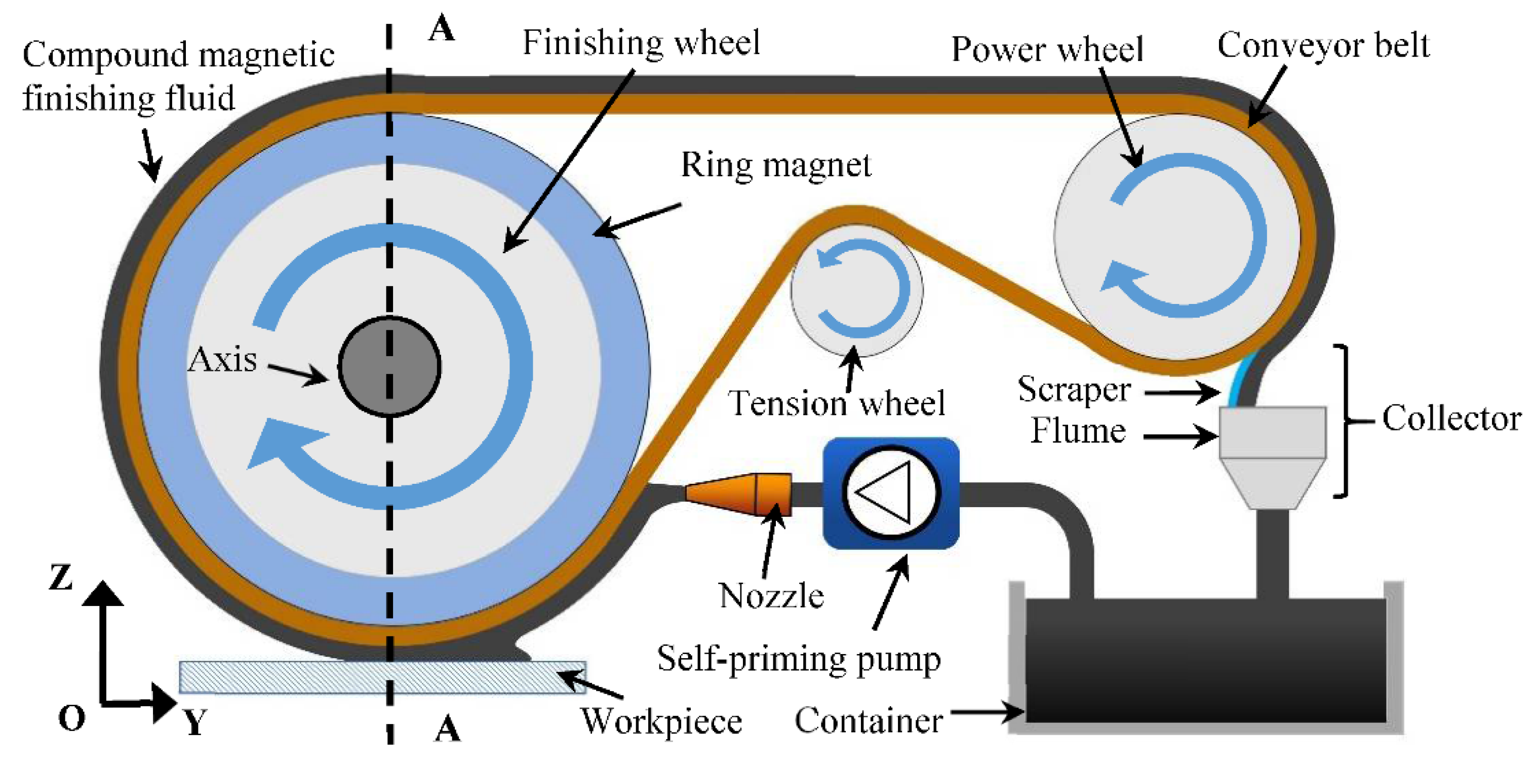
2.1. Principle of the MAF

Figure 1 shows the schematic of the processing. This process uses a magnetic field to make the compound magnetic finishing fluid (cutting fluid, iron powders, and abrasives) into slurry state to finish the workpiece. The process includes a transmission part and a liquid circulation part. The transmission part is mainly composed of finishing wheel, tension wheel, power wheel, and conveyor belt. The liquid circulation part is mainly responsible for the recovery, storage, and supply of compound magnetic finishing fluid. The function of the power wheel is to provide power for the conveyor belt, the function of the tension wheel is to tension the conveyor belt, and the function of the finishing wheel is to provide magnetic field and support for the conveyor belt and the compound magnetic finishing fluid in the finishing area. The conveyor belt is the carrier of the compound magnetic finishing fluid, which transports the compound magnetic finishing fluid to complete a series of processes. The schematic diagram of the experimental device is shown in Figure 2.
Figure 3 is a cross-sectional view of the finishing wheel, and the corresponding section line position is shown by the dashed line A-A in Figure 1. The cross-sectional view shows the internal structure of the finishing wheel, which is mainly composed of aluminum structural parts and ring magnets. The ring magnet is made of Nd-Fe-B, the outer diameter is 76 mm, the inner diameter is 42 mm, and the thickness is 6 mm. The N pole and S pole of the ring magnet are shown in red and blue respectively in Figure 3. The ring magnet and the aluminum structure together form a ring structure with grooves. The dimensions of the groove and the conveyor belt and the placement of the conveyor belt are shown in Figure 2 (partial cross-sectional view of the finishing wheel). The groove is used to restrain the conveyor belt and prevent the conveyor belt from moving sideways on the finishing wheel. The ring magnet is located in the middle of the finishing wheel, and the outer edge of the ring magnet is as high as the groove. The purpose of the ring magnet is close to the inner surface of the conveyor belt and provides a magnetic field for the compound magnetic finishing fluid on the outer surface of the conveyor belt.
The distribution of magnetic lines of force and the effect of the force on the magnetic particles are shown in Figure 3. For the magnetic particles located in the finishing area, the magnetic force Fy in the direction of the magnetic force line, and the magnetic force Fx in the direction of the equipotential lines of the magnetic force lines are received.
The forces F y . and F x are the magnetic forces that attract and gather magnetic particles on the conveyor belt. The magnetic forces F x , F y can be expressed by the following Equation (1) [29]:
F x = V χ μ 0 H ( H x ) F y = V χ μ 0 H ( H y )
where V is the volume of the magnetic particle, χ is the magnetic susceptibility of the magnetic particle, μ 0 is the permeability of vacuum, and H is the magnetic field density H / x . and H / y are the gradient of the magnetic field density in the x and y directions, respectively. The resultant force F of the magnetic force received by the magnetic particle i in Figure 3 can be expressed as Equation (2):
F = F x sin β i + F y cos β i
where, βi is the inclination angle of the magnetic field lines at the position where the magnetic particle i is located, and the force F m aligns the magnetic particles, which is a kind of magnetic force that makes the magnetic particles form a chain-like structure. F m can be expressed by the following Equation (3) [29]:
F m = 1.5 π r 2 X r 2 μ 0 H 2 / ( 3 + X r ) 2
where r is radius of magnetic particles, respectively, X r is specific susceptibility of magnetic particles, μ 0 is the permeability of vacuum. As a result, the magnetic particles attract each other to form a whole, and tightly attached to the surface of the conveyor belt under the action of the magnetic field force, move with the conveyor belt to be used as finishing tool. As shown in the bottom figure of Figure 3, when the conveyor belt drives the integrated magnetic particles to move, the magnetic particles move relative to the workpiece. So as to realize the finishing of the workpiece.
During finishing, the finishing wheel rotates in the direction shown in Figure 1. The magnetic finishing fluid in the bottom area of the finishing wheel is taken away from the finishing area immediately after finishing the workpiece. At this time, after the compound magnetic finishing fluid is squeezed, the shape changes. Due to the effect of the magnetic field of the finishing wheel, the compound magnetic finishing fluid will always maintain the slurry state and be taken from the bottom of the finishing wheel to the upper part of the finishing wheel. The conveyor belt continues to move, and the compound magnetic finishing fluid will be brought to the horizontal area of the conveyor belt in the next step. At this stage, the compound magnetic finishing fluid will break away from the influence of the magnetic field and return to a liquid state. It will keep the liquid state until it reaches the power wheel, and is scraped off by the elastic scraper at this position, and flows along the flume into the container under the collector under the action of gravity. The compound magnetic finishing fluid in the container will be driven by the self-priming pump along the pipeline to the nozzle, and from the nozzle to the surface of the conveyor belt that is attached to the finishing wheel. Under the action of the magnetic field, the compound magnetic finishing fluid immediately transforms into a slurry state. In the next step, it is transported by the conveyor to the bottom area of the finishing wheel, the finishing area, to finish the workpiece, and then it will be taken away from the finishing area. Such a cyclic process realizes the use of compound magnetic finishing fluid to finish the workpiece. At the same time, the continuous update of compound magnetic finishing fluid, that is, the update of abrasive particles, is realized.

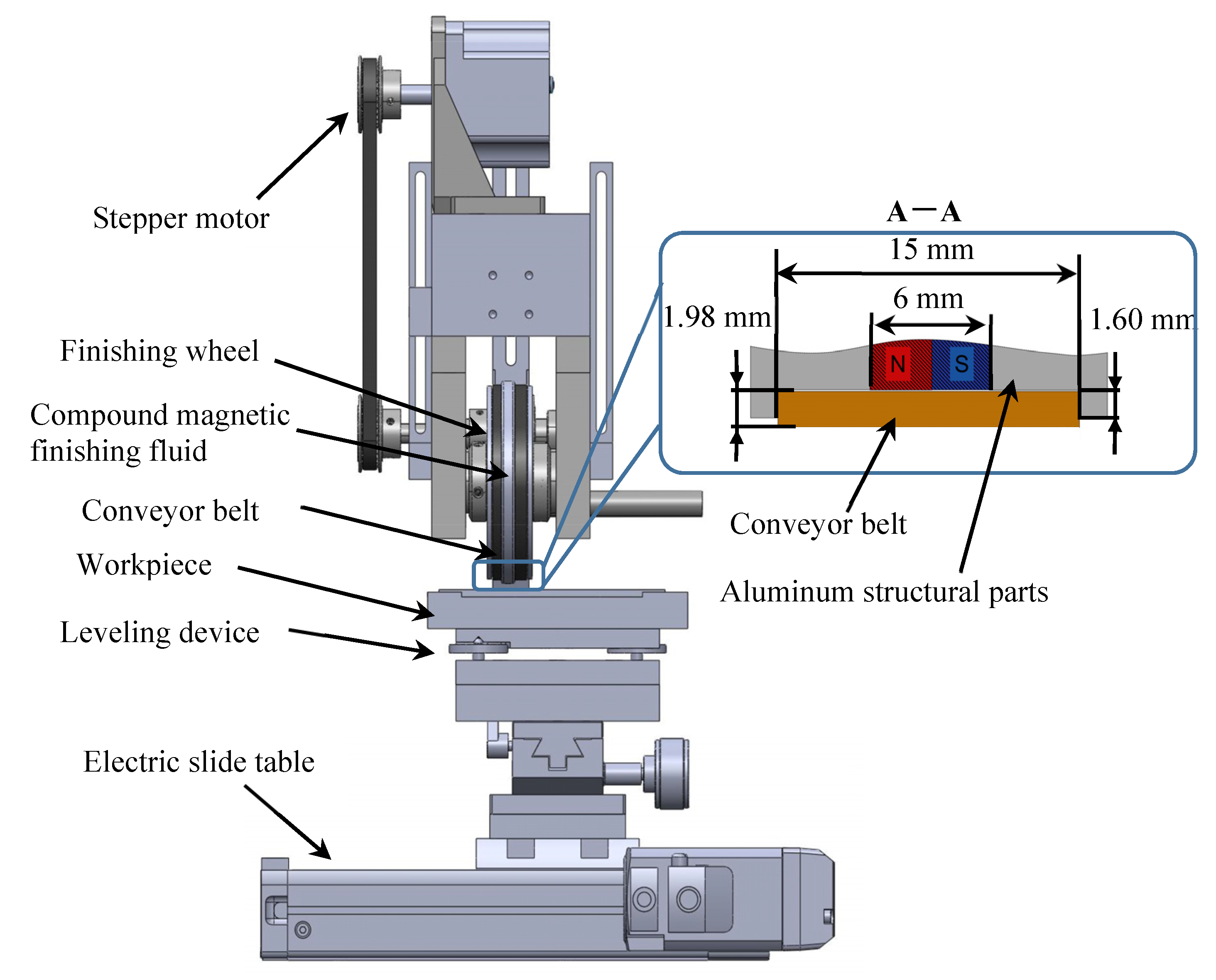
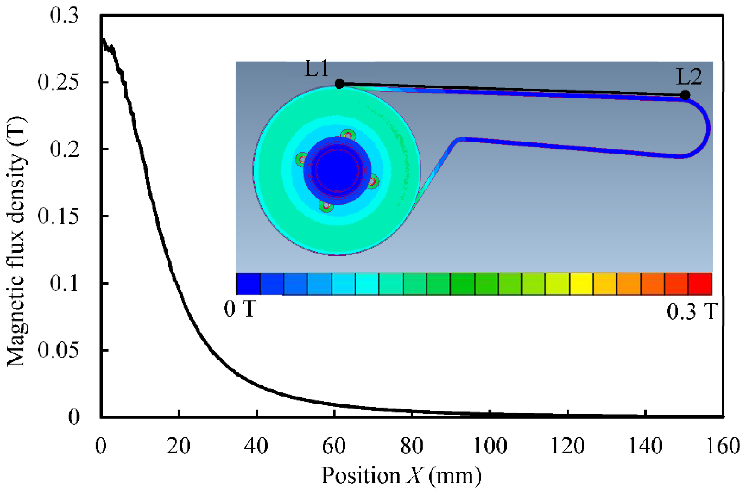
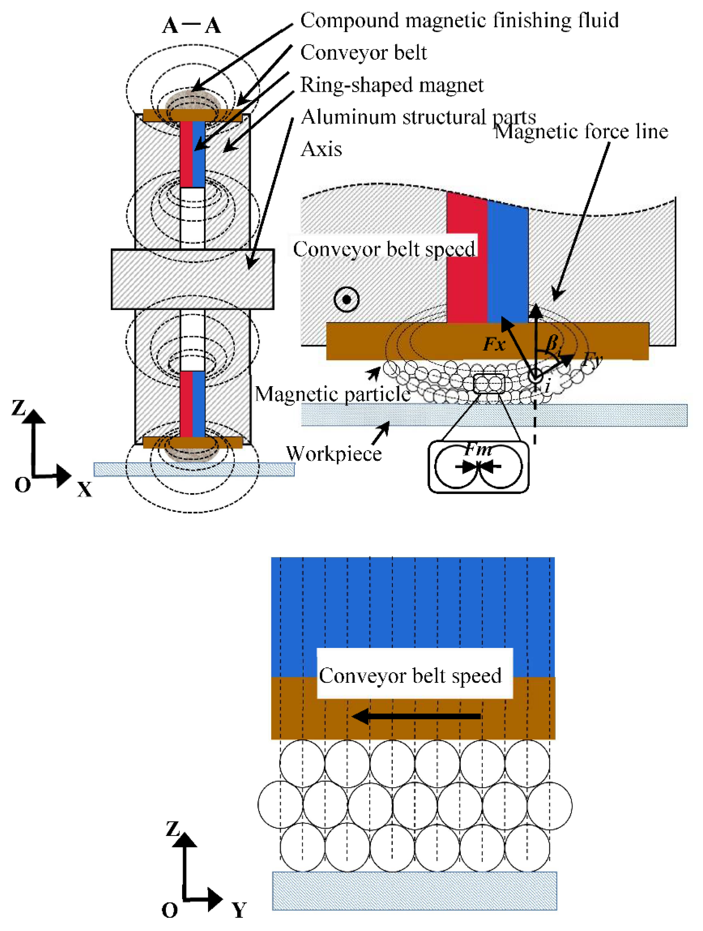
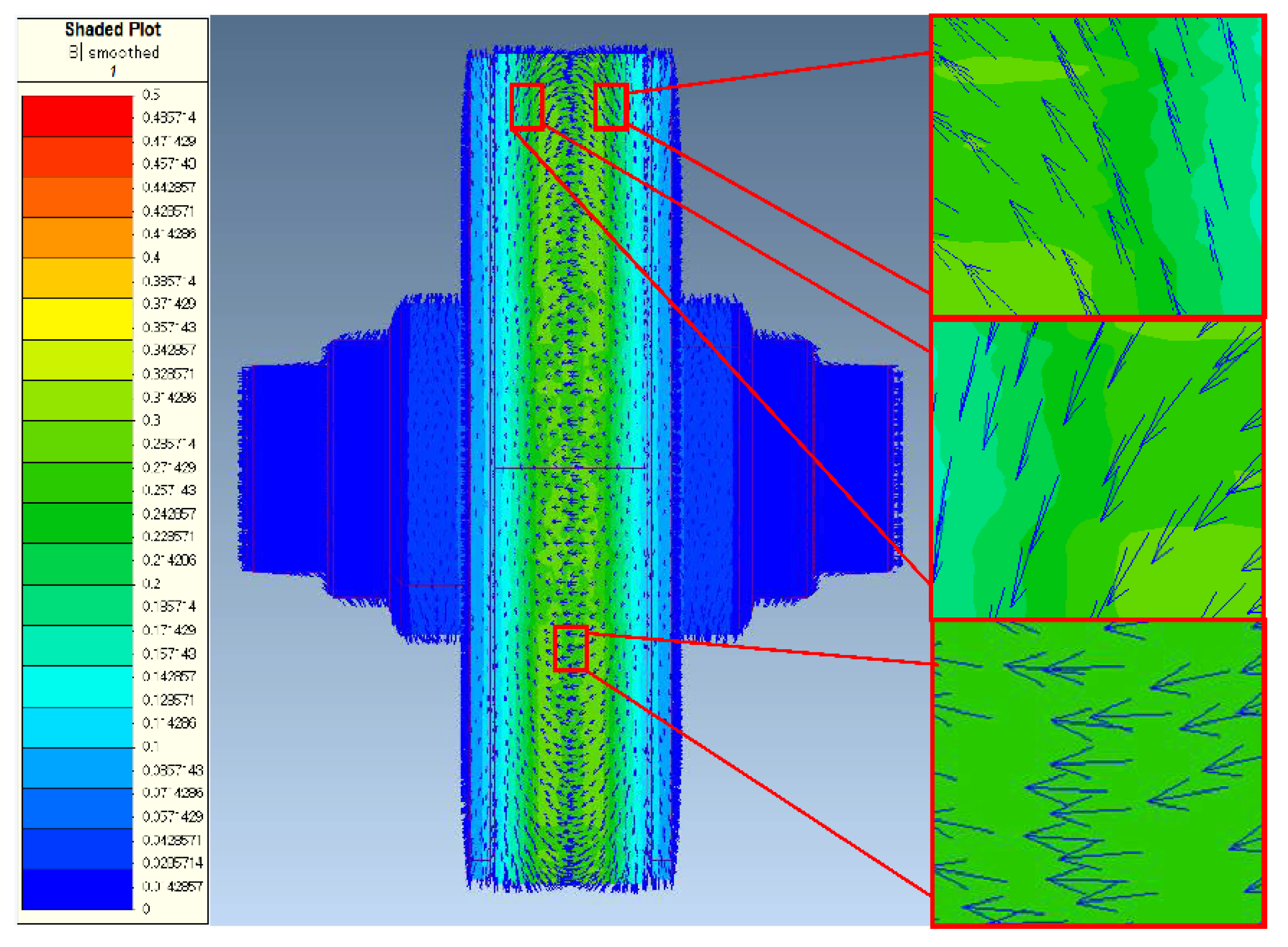
2.2. Analysis of Magnetic Field

As mentioned in the previous Section 2.1, the finishing wheel plays a vital role in the entire processing method. Compound magnetic finishing fluid is moved by the conveyor belt, used to finish the workpiece. At the same time, the used compound magnetic finishing fluid needs to be recovered smoothly. The above process requires the cooperation of the magnetic field formed by the ring magnet of the finishing wheel and the movement of the conveyor belt. Therefore, in order to further explore the mechanism of this process, it is necessary to explore the magnetic field distribution of the finishing wheel and the conveyor belt.

2.2.1. Magnetic Field in the Direction of Conveyor Belt Movement

As shown in Figure 4, point L1 is the highest point of the finishing wheel, and the distance between point L2 and point L1 is 160 mm. The L1L2 line segment is located at the centerline of the conveyor belt surface. In this paper, the magnetic field analysis software “Magnet7” developed by Infolytica Corporation is used to simulate the magnetic field. The simulation result of the change of the magnetic field intensity on the L1L2 line segment is shown in Figure 4. The horizontal axis X represents different positions on the line segment L1L2, and the origin is L1. Observing the change curve of magnetic field strength, it is found that the magnetic field strength decreases sharply in the range of 0 to 20 mm. The weakening trend of magnetic field strength slows down in the range of 20 to 100 mm, and the value of magnetic field strength remains close to 0 after 100 mm. This shows that the compound magnetic finishing fluid will be almost out of the influence of the magnetic field when it moves to a position of 100 mm under the drive of the conveyor belt. This allows the compound magnetic finishing fluid to remain liquid after 100 mm and reach the power wheel in this state. The different states of compound magnetic finishing fluid in the finishing wheel area and the power wheel area are shown in Figure 5, the compound magnetic finishing fluid is in a slurry state under the influence of the magnetic field and adheres to the surface of the conveyor belt. At the position of the power wheel, it can be seen that the compound magnetic finishing fluid has been completely restored to a liquid state, therefore it is easily separated from the conveyor belt by the scraper.

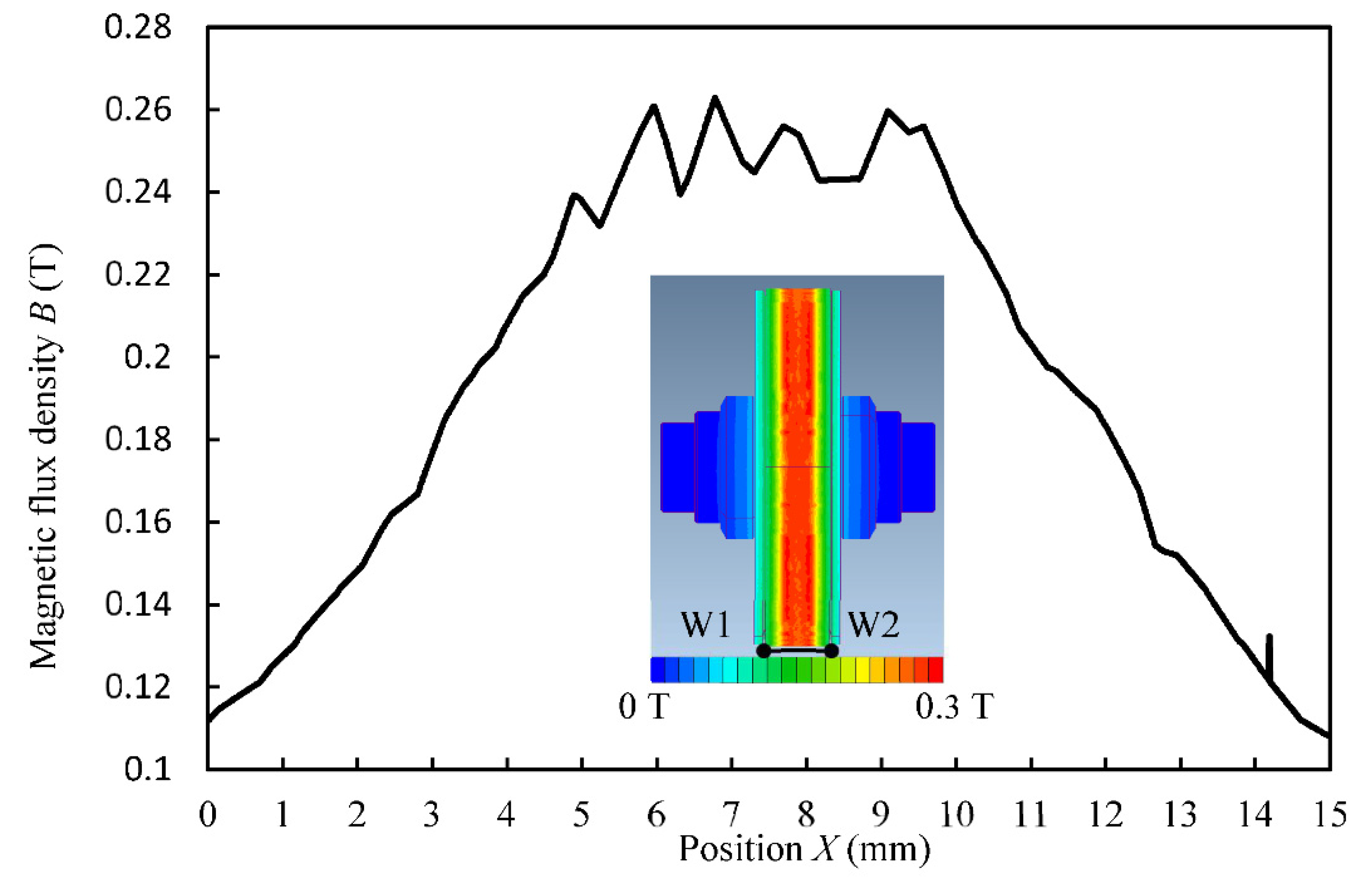
2.2.2. Magnetic Field in the Width Direction of the Conveyor Belt

Figure 6 is a simulation result of the magnetic field distribution on the surface of the conveyor belt on the finishing wheel and the change of the magnetic field intensity in the width direction of the conveyor belt. As shown in the illustration in Figure 6, the line segment W1W2 coincides with the width of the conveyor belt and is located at the lowest point at the bottom of the finishing wheel. The length of the line segment W1W2 is 15 mm, the same as the width of the conveyor belt, and the magnetic field intensity change curve in Figure 6 is the magnetic field distribution on the line segment W1W2. The horizontal axis X represents different positions on the line segment W1W2, and the origin is W1. Observing the magnetic field intensity curve shows that the magnetic field intensity is relatively high in the 4.5 to 10.5 mm interval of the line segment W1W2.
However, the magnetic field strength changes significantly in the 0 to 4.5 mm and 10.5 to 15 mm intervals of the line segment W1W2. As the distance from the center position increases, the magnetic field strength decreases sharply. The location and range of the area with strong magnetic field distribution coincide with the 6 mm width of the ring magnet under the conveyor belt. It shows that the compound magnetic finishing fluid will maintain a certain strength slurry state within the width of the ring magnet, and can stably gather in the middle of the conveyor belt.
Figure 7 shows the simulation results of the direction of the magnetic field vector of the finishing wheel and the conveyor belt. The partial enlarged view on the right corresponds to the direction of the magnetic field vector on both sides of the conveyor belt and the middle position. The simulation results show that the magnetic field lines start from one side of the conveyor belt, and the magnetic field lines are parallel to the conveyor belt in the middle of the conveyor belt, and then change direction to reach the other side of the conveyor belt. This is consistent with the effect of the magnetic lines of force analyzed above, that is, the magnetic particles in the compound magnetic finishing fluid will form an arched structure on the surface of the conveyor belt under the action of such magnetic lines of force to realize the finishing of the workpiece.

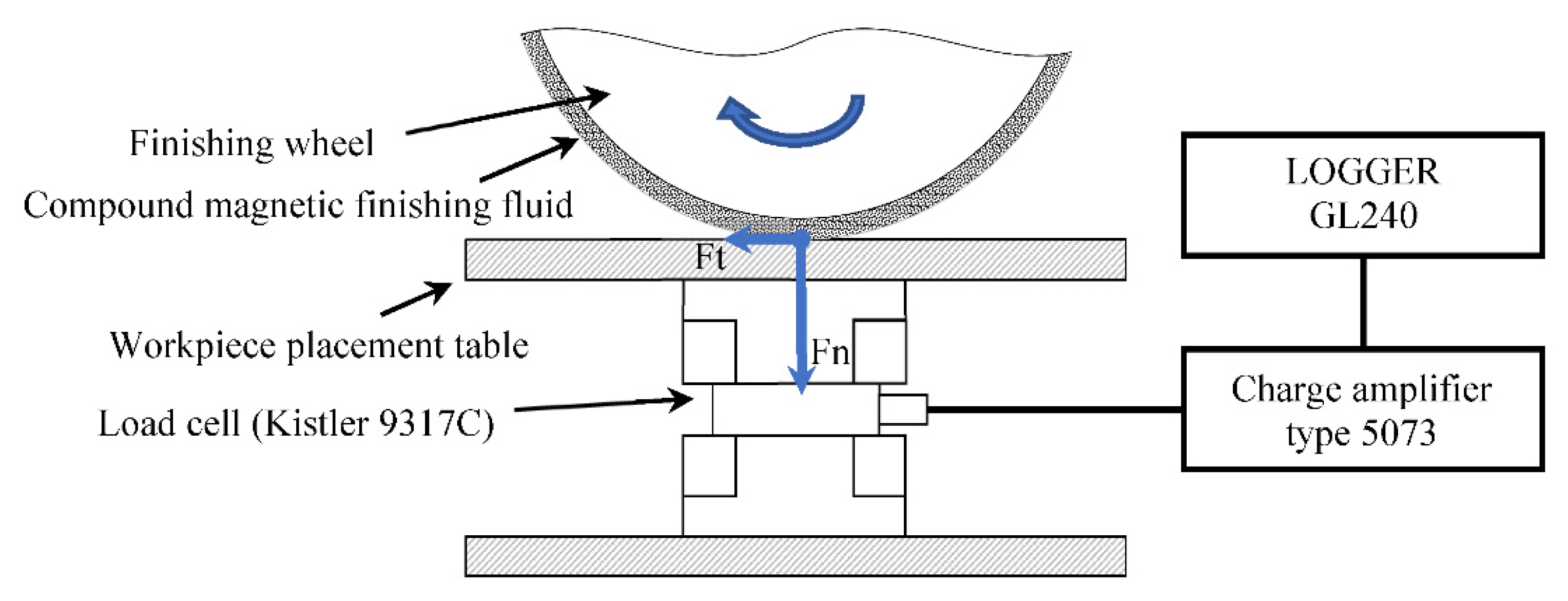
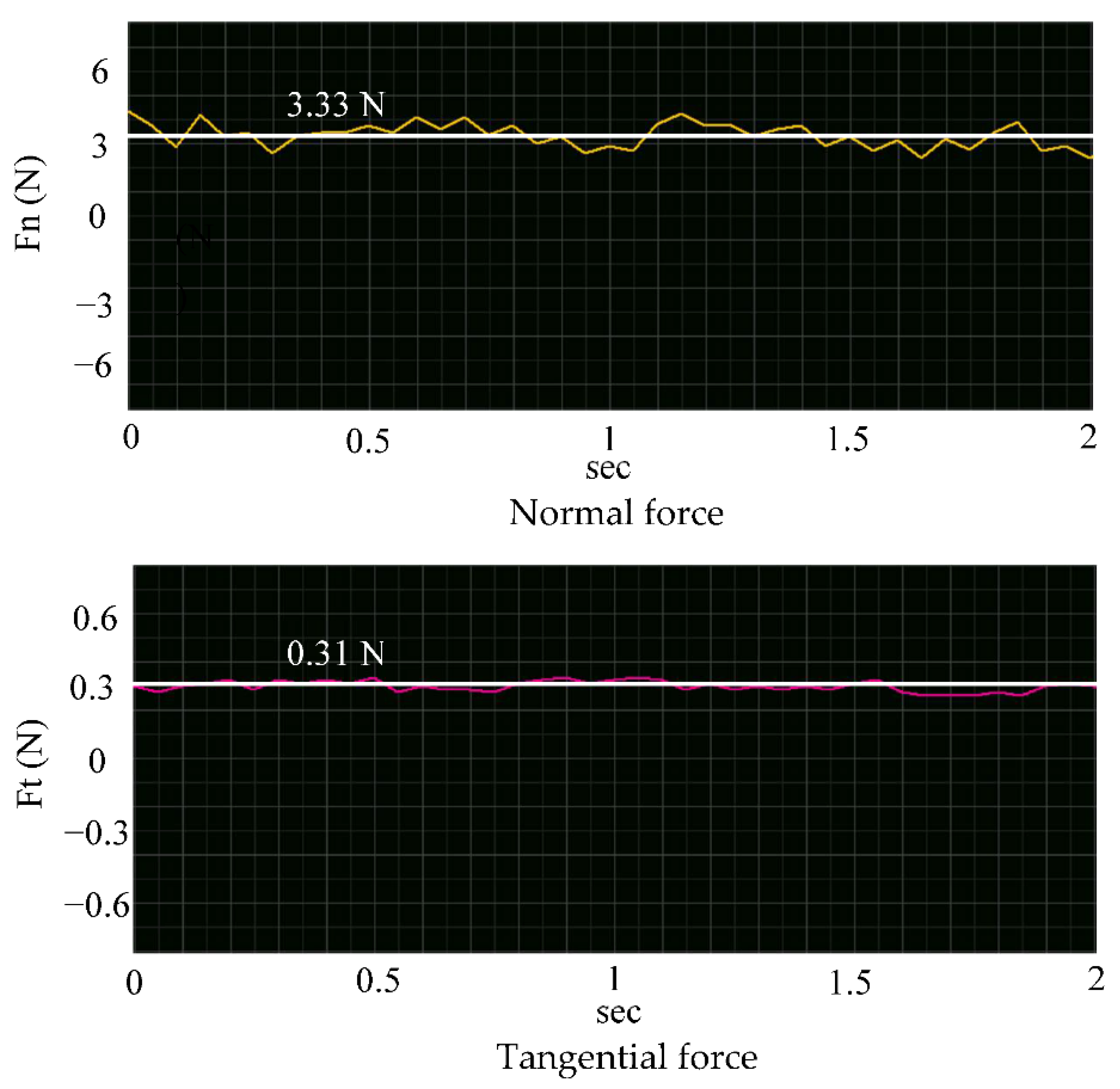
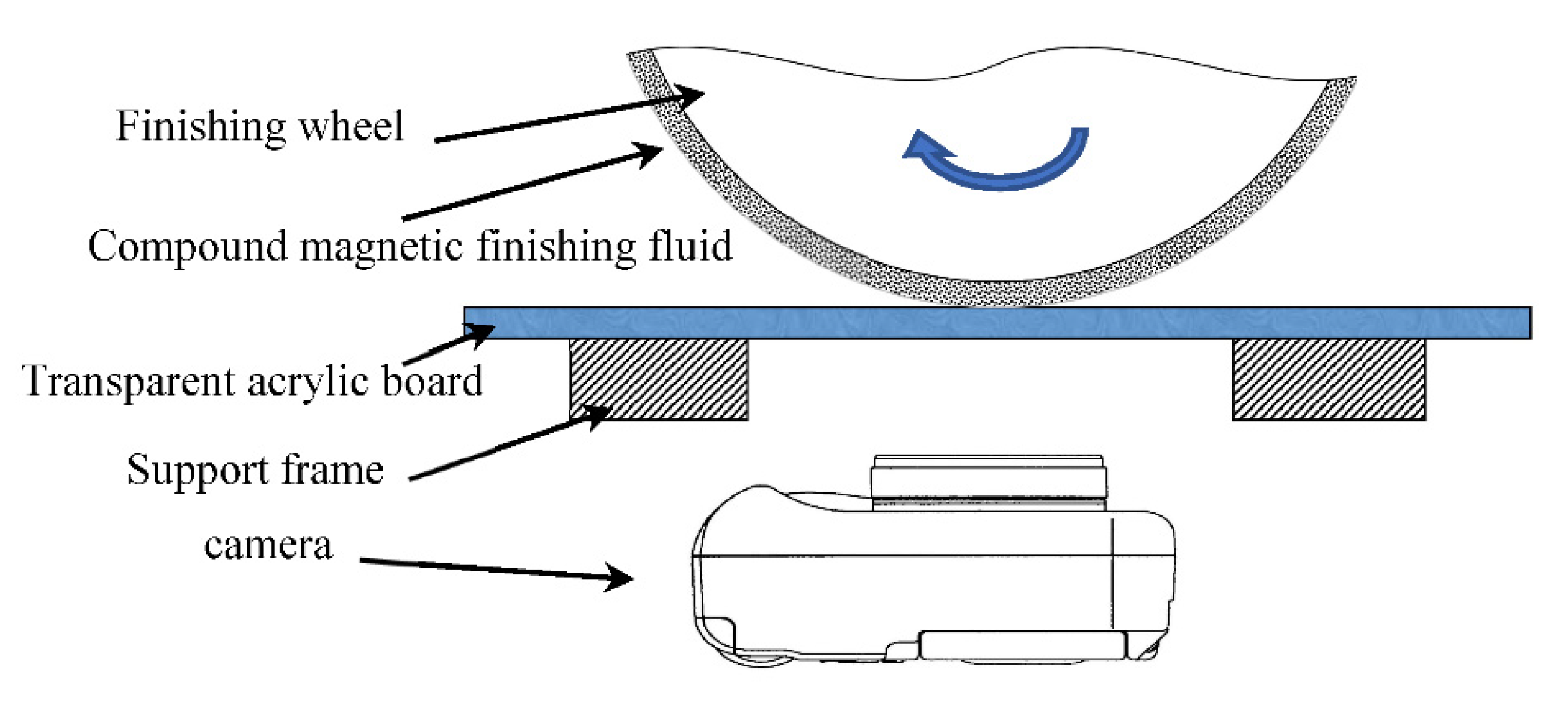
2.3. Finishing Force Measurement

In order to further explore the finishing effect of the finishing wheel, the finishing force during the finishing process was measured. The schematic diagram of the force measurement system is shown in Figure 8. The normal force Fn and tangential force Ft generated during the finishing process are measured using a three-component load cell (Kistler 9317C produced by Kistler Group, Winterthur, Switzerland) and a charge amplifier (Type 5073 Kistler produced by Kistler Group, Winterthur, Switzerland), and are recorded by being connected to the recorder (LOGGER GL240 produced by NIHON DENKEI Co. Ltd., Tokyo, Japan). The measurement conditions are shown in Table 1.
In this measurement, we studied the influence of working gap and workpiece material on finishing force. Figure 9 shows the waveform of the force measurement, which corresponds to the normal force and tangential force of the polychlorotrifluoroethylene resin plate at a working gap of 0.1 mm. In order to compare the changes in force under different conditions, the measured data are averaged, as shown by the white horizontal lines and white digital marks in Figure 9. Figure 10 shows the comparison of the finishing force of the stainless steel workpiece and the resin plate workpiece when the working gap is 0.1 and 0.06 mm, respectively. As the working gap decreases, the finishing force increases. This is because the finishing wheel in this process not only plays a role in providing a magnetic field to change the state of the compound magnetic finishing fluid, but also plays a role in supporting the conveyor belt and the compound magnetic finishing fluid to generate pressure on the workpiece. In the finishing area, the compound magnetic finishing fluid in the slurry state has a certain strength. The reduction of the working gap also squeezes the compound magnetic finishing fluid. In turn, the compound magnetic finishing fluid in the slurry state resists deformation while also applying pressure to the workpiece. In addition, it should be noted that the normal force of different workpieces is roughly the same under the same working gap. However, the tangential force of the stainless steel plate is greater than the tangential force of the resin plate. When the workpiece is cut, the cutting force will be affected by the hardness of the material being cut. As the hardness of the material increases, the cutting force will also increase [30]. The hardness tester (SHIMADZU hmv-1) was used to measure the hardness of the workpieces of two materials, and the result shows that the hardness value of polychlorotrifluoroethylene resin plate (11 HV) is less than the hardness value of SUS304 stainless steel plate (277 HV), so under the same working gap, the measurement result of the tangential force of the SUS304 stainless steel plate is larger.

3. Experimentation

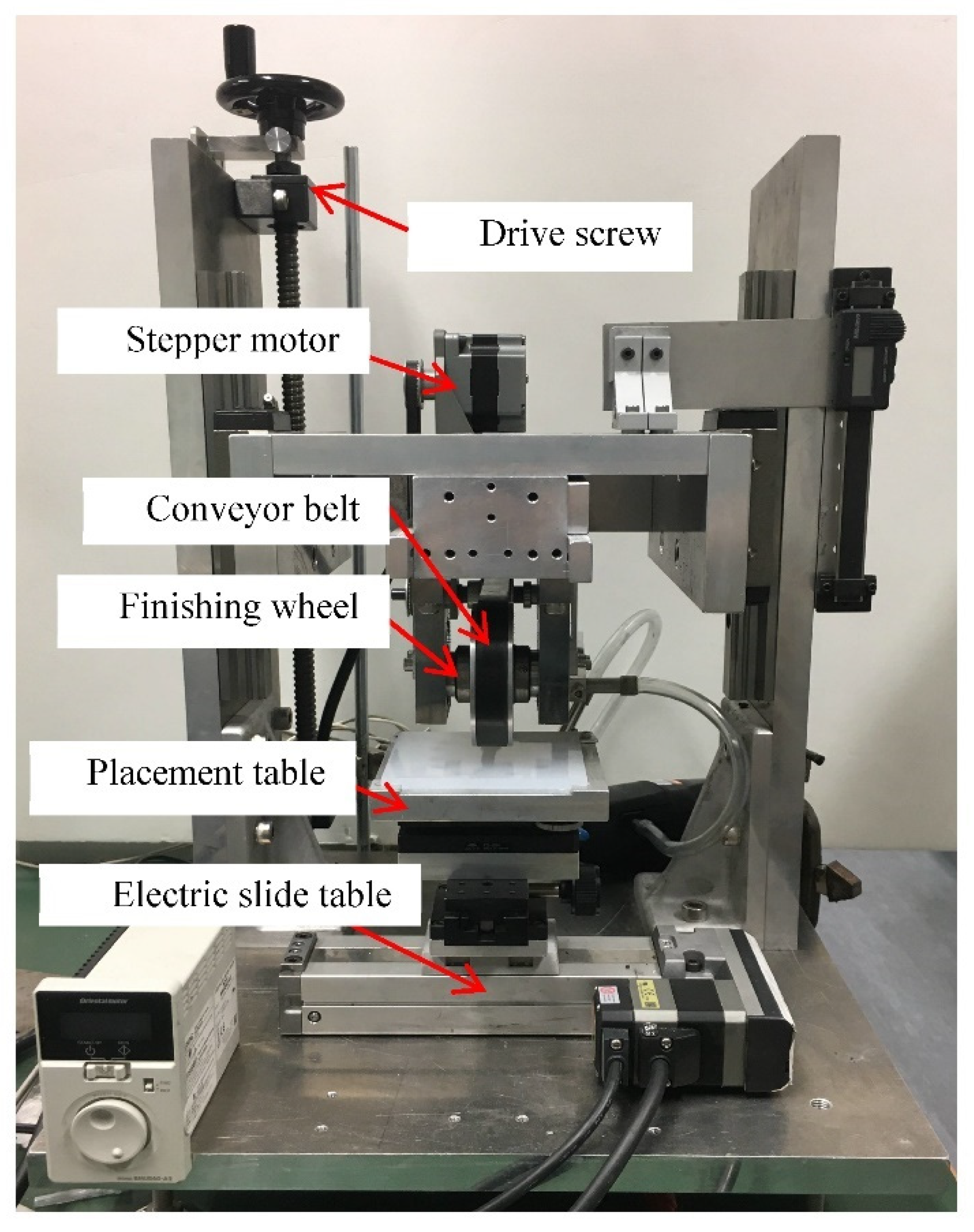
3.1. Experimental Setup

The external view of the experimental device is shown in Figure 11. Below the finishing wheel is a placement table to set the polychlorotrifluoroethylene resin plate with a size of 100 × 100 × 6 mm as workpiece. The electric sliding table can move the placement table in the X direction.

3.2. Experimental Methods and Conditions

This study studied the effects of iron powder particle size, working gap, and abrasive particles on the finishing performance. We prepared compound magnetic finishing fluid with carbonyl iron powder with 3.4–4.5 µm in mean diameter and electrolytic iron powder with 30 µm in mean diameter. Electrolytic iron powder and carbonyl iron powder have superior magnetic properties as soft magnetic materials. On the other hand, the compound magnetic finishing fluid prepared from them has good fluidity. Therefore, when there is a magnetic field, they can form a certain regular arrangement, so that the compound magnetic finishing fluid can complete the transition from liquid to slurry state. In order to understand the change of material finish with time, we measure the workpiece at regular intervals. A total of 0.12 mL cutting fluid is replenished every 5 min to offset the loss in the finishing process. In the experiment, the surface roughness was measured with a surface roughness tester (Surftest SV-624-3D produced by Mitutoyo Corporation, Kawasaki, Japan).

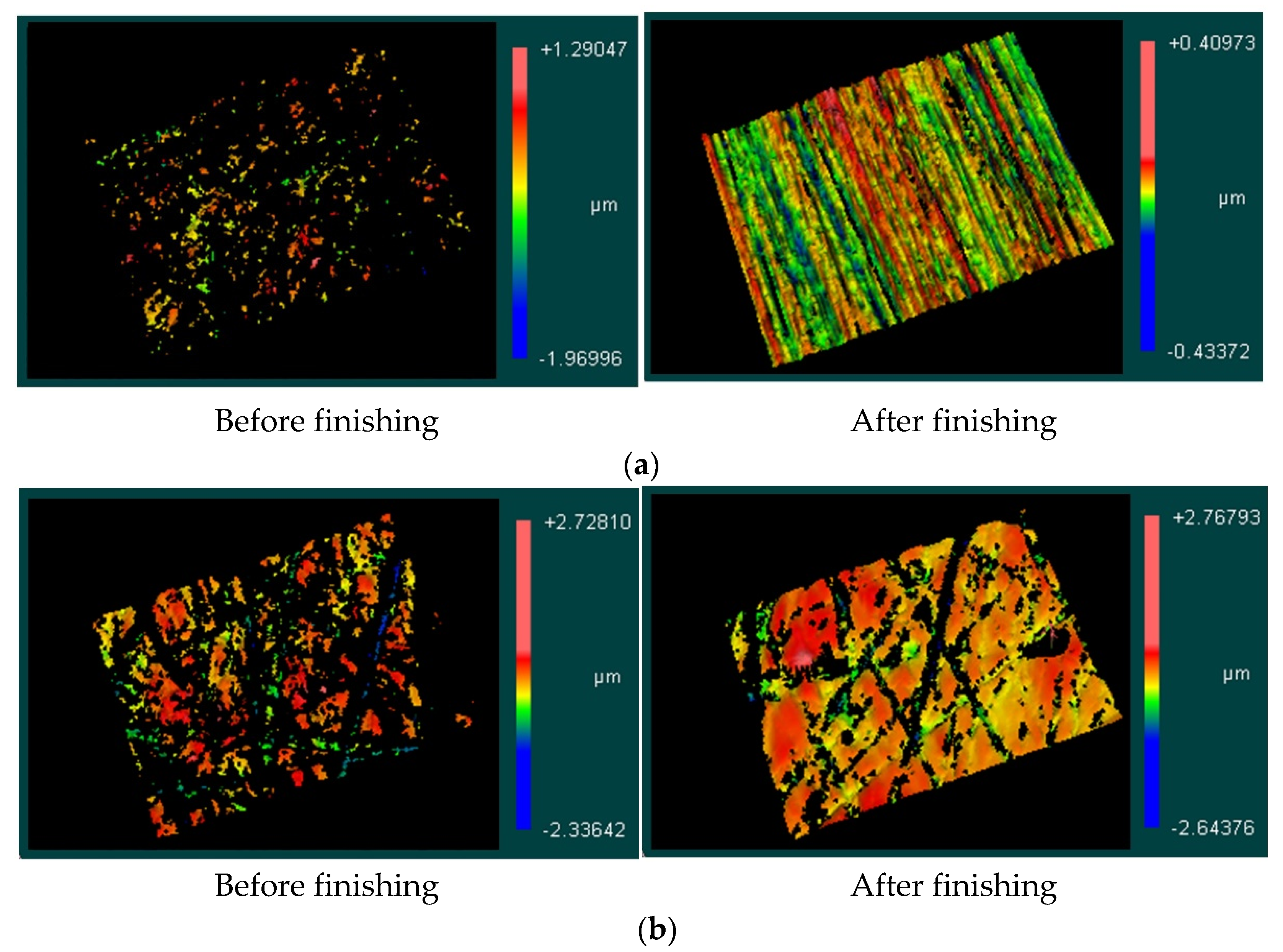
4. Experimental Results and Discussion

The influence of magnetic particles size, working gap, and abrasive particles on the finishing characteristics are discussed in the following subsections.

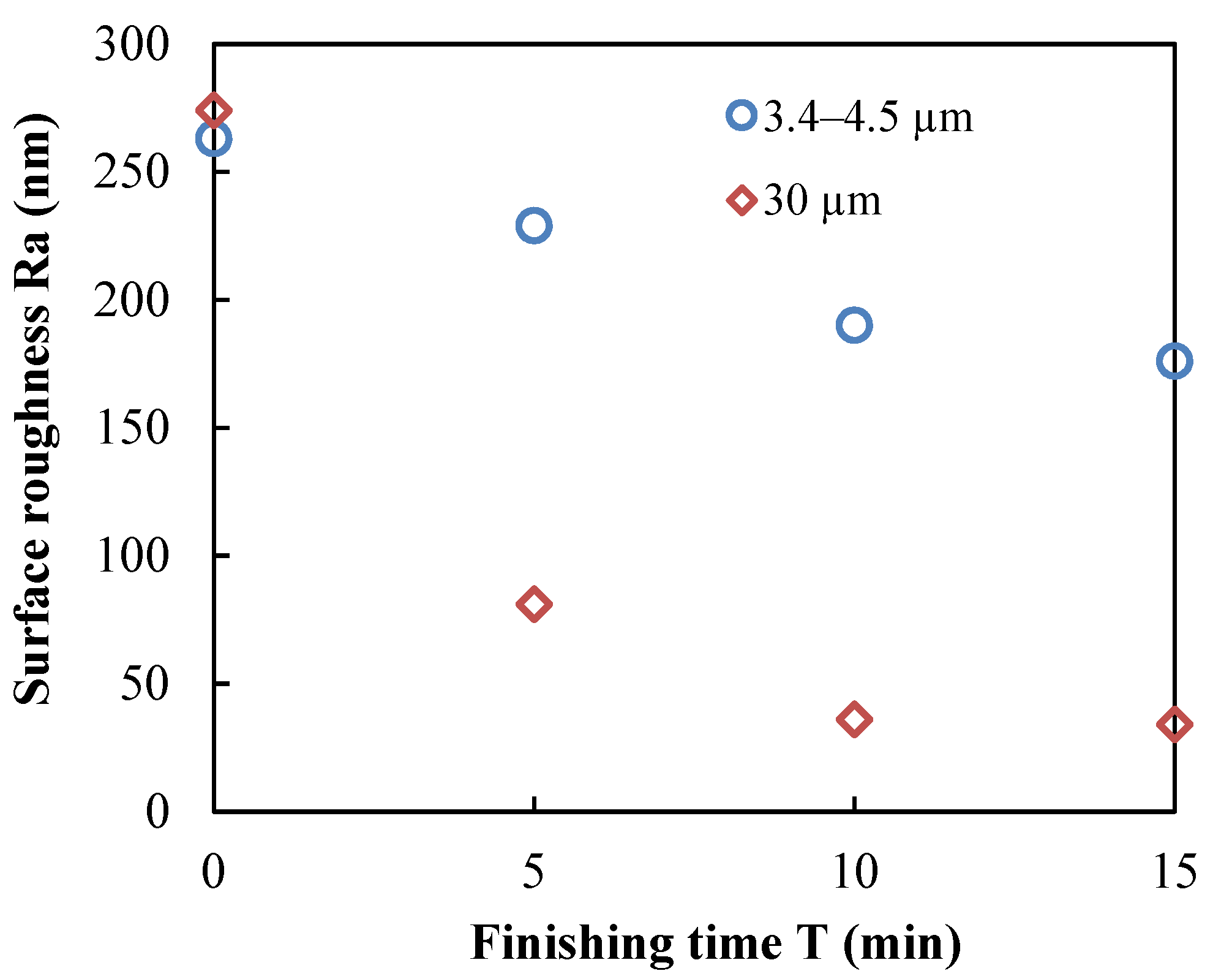
4.1. Iron Powder Particle Size
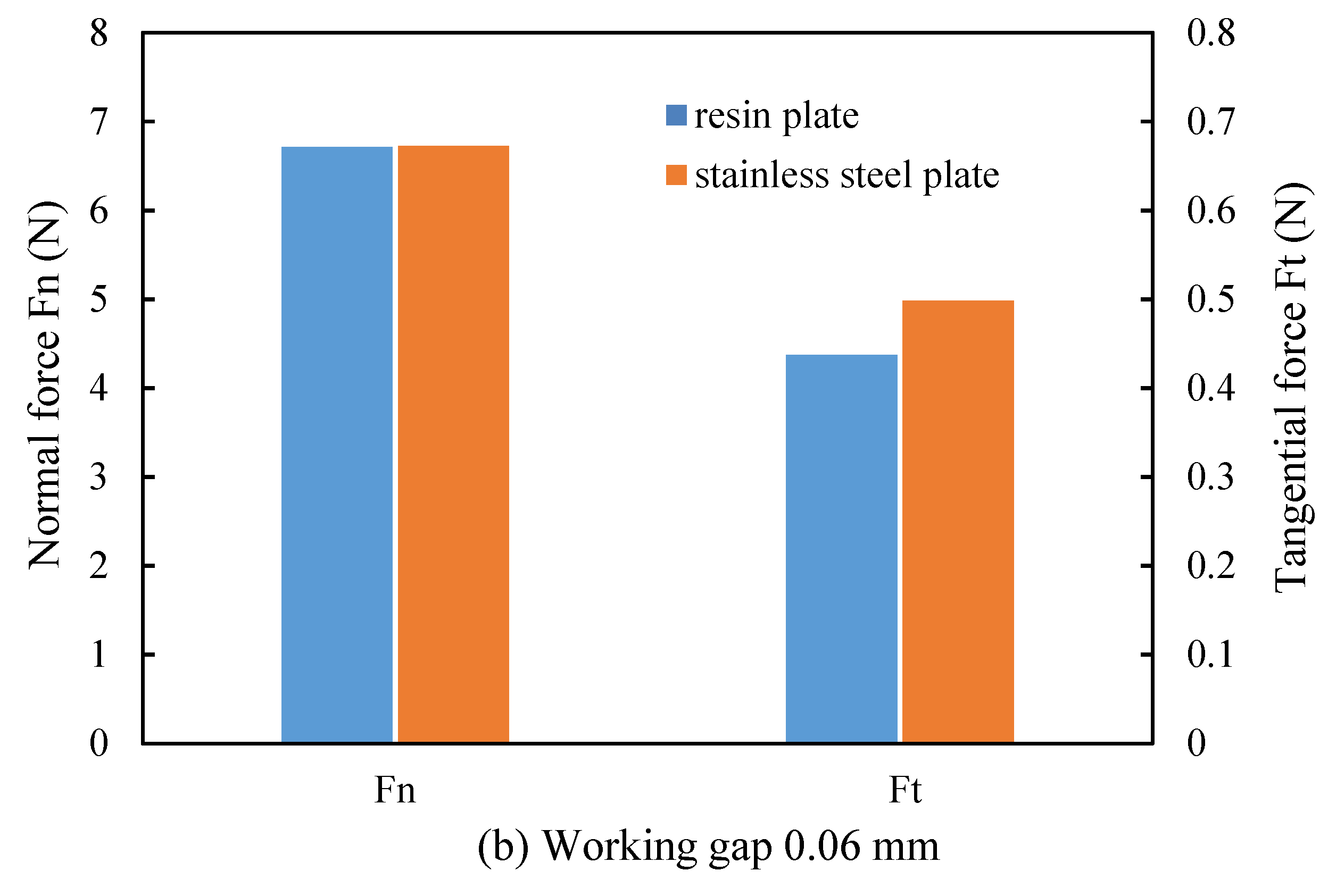
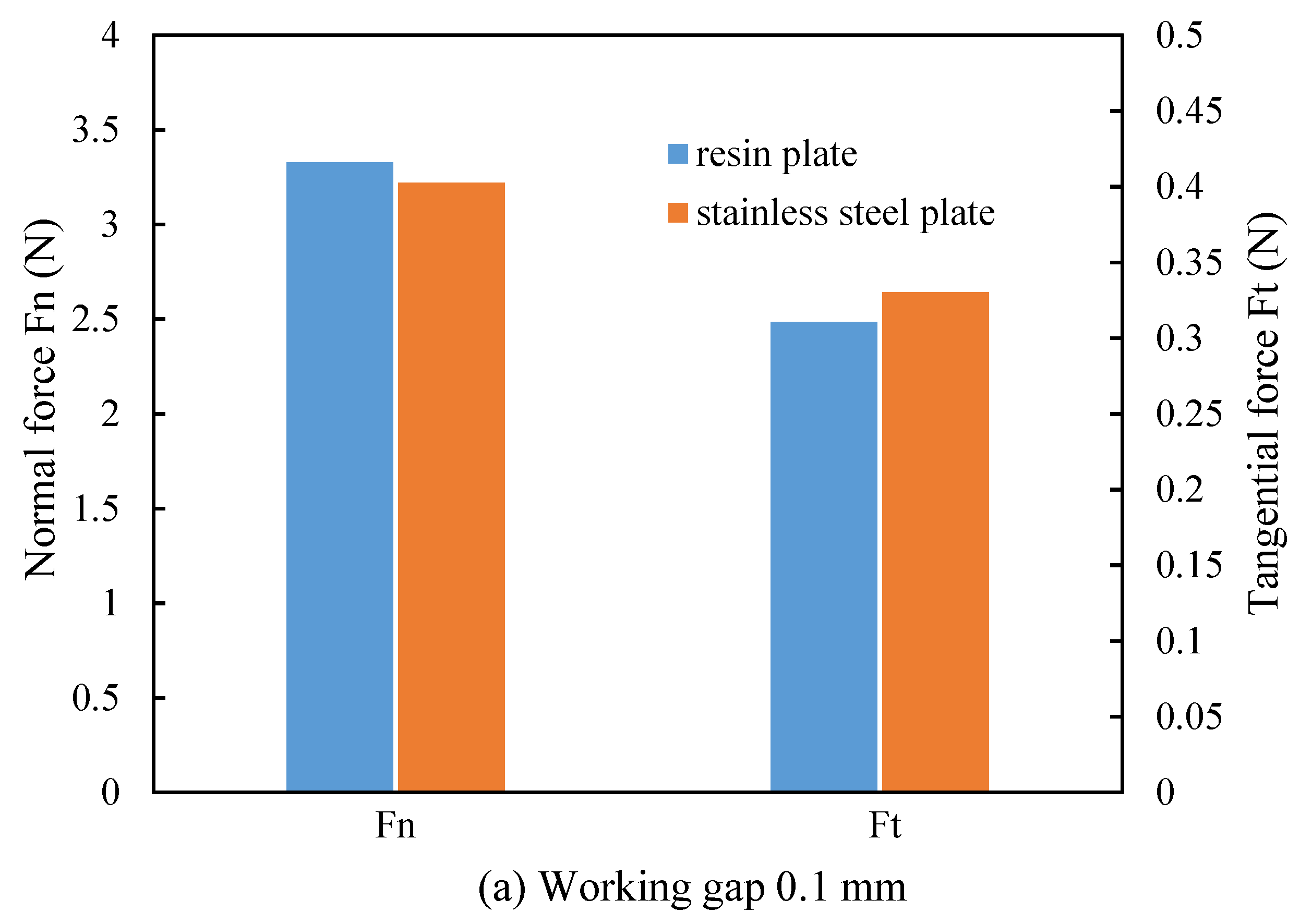
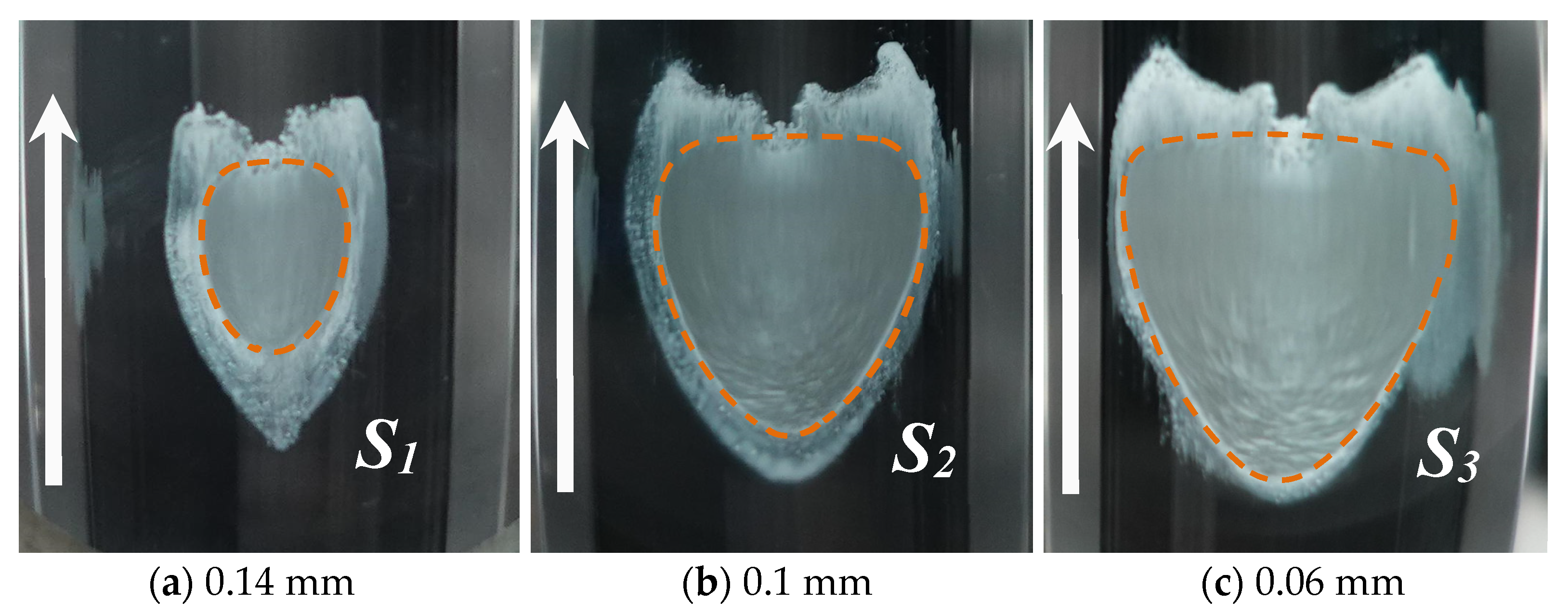
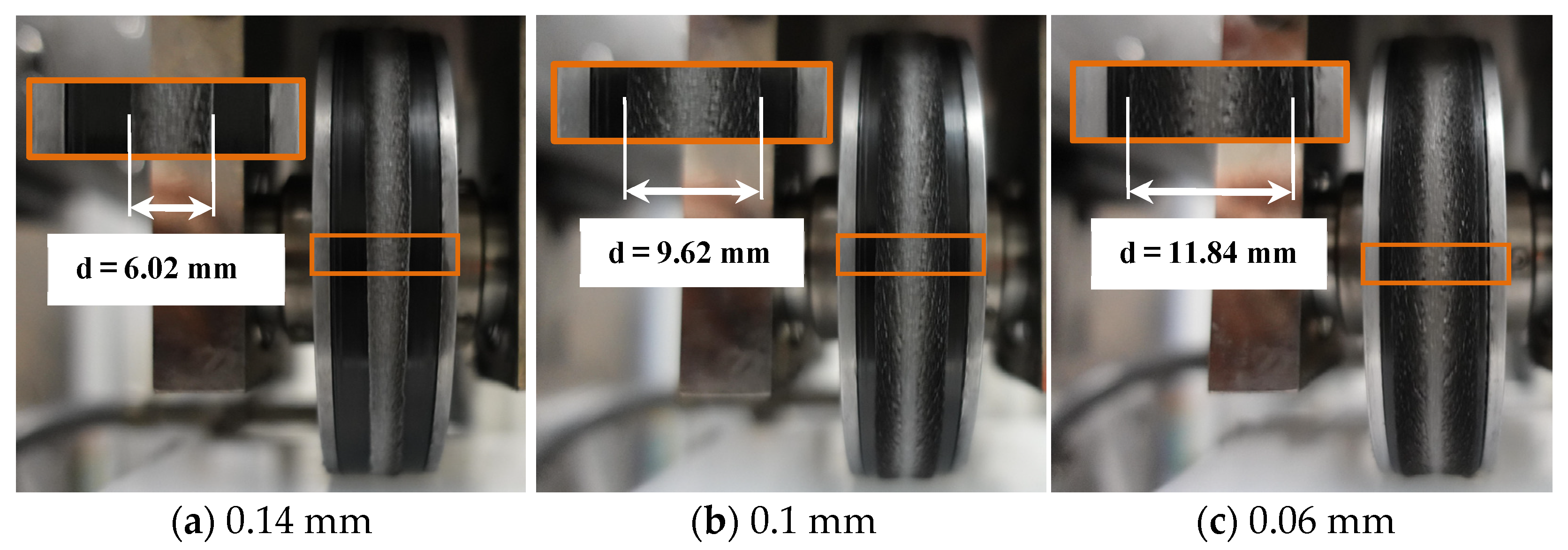
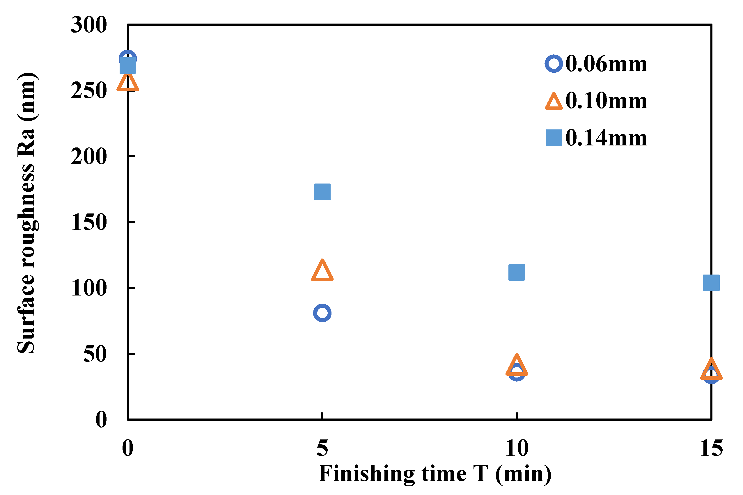
Iron powder is an important part of the compound magnetic finishing fluid, and it is the basis for the state of the compound magnetic finishing fluid to change under the action of a magnetic field. At the same time, it is also the carrier of abrasive particles and affects the distribution of abrasives. Therefore, the performance of the iron powder is the basis for ensuring the quality and efficiency of the finishing.
The experimental conditions are shown in Table 2. Under the condition that the working gap is 0.06 mm and the abrasive particle size is WA#10000, use 30 µm in mean diameter Electrolytic iron powder and 3.4–4.5 µm in mean diameter carbonyl iron powder. A finishing experiment was carried out. Figure 12 shows the effect of different particle sizes of iron powder on the finished surface. It can be seen that the faster surface roughness improvement efficiency can be obtained when electrolytic iron powder with 30 µm in mean diameter is used, and the surface roughness of the workpiece is improved from 274 to 34 nm, a better surface roughness improvement effect can be obtained. In contrast, when carbonyl iron powder with 3.4–4.5 µm in mean diameter was used, the surface roughness of the workpiece is improved from 263 to 176 nm, and it is difficult to obtain a finished surface with better surface quality. The finishing performance of different iron powder particle size is obviously different. Because the iron powder is arranged in a certain structure according to the magnetic lines of force on the surface of the conveyor belt, the compound magnetic finishing fluid can be transformed from a liquid state to a slurry state with a certain strength, and thus has the ability to finish the surface of the workpiece. Therefore, iron powder is a key factor in determining the state of compound magnetic finishing fluid in a magnetic field. From the previous Equation (2), it can be seen that the force Fm between magnetic particles is proportional to the square of the radius of the magnetic particles. As the particle size of the iron powder increases, Fm will also increase significantly. Therefore, when the compound magnetic finishing fluid becomes a slurry state with a certain strength under the action of a magnetic field, when the workpiece is finished by flexible contact, the larger iron powder particle size brings higher strength, and the workpiece receives a stronger effect.
Figure 13 is the 3D topography of the workpiece surface before and after finishing measured by NewView 7300 optical profiler (produced by Zygo Corporation, Philadelphia, PA, America). By observing the finishing surface using different magnetic particle sizes, it can be found that when 30 µm in mean diameter, electrolytic iron powder is used, the initial texture of the finishing area has been completely removed, and replaced by the finished texture. The direction of the texture of the finishing area after finishing is uniform, which is the same as the movement direction of the compound magnetic finishing fluid. When 3.4–4.5 µm in mean diameter, carbonyl iron powder is used, the surface morphology of the finished area after finishing is slightly improved compared to that before finishing. Some shallow grooves are improved or even eliminated. At the same time, the undulations of the finished surface topography tend to be gentle. However, there are still some deep grooves that have not been eliminated. Therefore, compared to 3.4–4.5 µm in mean diameter, carbonyl iron powder, when 30 µm in mean diameter, electrolytic iron powder is used, a better effect of improving the surface roughness of polychlorotrifluoroethylene resin plate is obtained under current experimental conditions.

4.2. Working Gap

In this experiment, we studied the influence of working gap on finishing force and finishing surface. The experimental conditions are shown in Table 3. Under the condition that the abrasive particle size of the electrolytic iron powder of 30 µm in mean diameter is used for finishing experiments at working gaps of 0.06, 0.1, and 0.14 mm. In order to explore the finishing mechanism under different working gaps, we placed the transparent acrylic board under the compound magnetic finishing fluid, and looked through it from under the transparent acrylic board to observe the contact of the compound magnetic finishing fluid on the transparent acrylic board in the finishing area as shown in Figure 14. The changes of compound magnetic finishing fluid observed from under the transparent acrylic board under different working gaps are shown in Figure 15. The direction of the arrow in the figure represents the direction of movement of the compound magnetic finishing fluid. When the compound magnetic finishing fluid is in contact with the transparent plate, it will produce contact points. The dotted line mark in the figure represents the range of the contact point. Obviously, under different working gaps, the area of the contact point will change. When the working gap is 0.14, 0.1, and 0.06 mm, the contact area S1, S2, and S3 are 32.64, 106.11, and 139.01 mm2, respectively. This is because with the reduction of the working gap, the compound magnetic finishing fluid receives a stronger squeezing effect in the finishing area, and therefore produces more obvious deformation, which is reflected in the increase in the contact area of the workpiece, which also means the compound magnetic finishing fluid has closer contact with the workpiece, resulting in a stronger finishing effect on the workpiece. At the same time, it should be noted that the shape of the contact point also has certain characteristics. Along the movement direction of the compound magnetic finishing fluid, it presents a wide front and narrow shape distribution. This shape shows that the compound magnetic finishing fluid is in an undeformed state when it first contacts the workpiece, and its width is relatively narrow, so the width of the contact point generated when it comes into contact with the workpiece is relatively narrow. As the compound magnetic finishing fluid conveyor belt continues to move forward, the compound magnetic finishing fluid is squeezed more strongly, resulting in an increase in the width of the contact point. When the width is increased to the widest, the compound magnetic finishing fluid will also adhere to the conveyor belt and leave the finishing area and end the contact with the workpiece. Therefore, the shape of the contact point in the Figure 15 is left. As shown in Figure 16, it is the width change distributed on the surface of the conveyor belt when the compound magnetic finishing fluid leaves the finishing area under different working gaps. When the working gap is 0.14, 0.1, and 0.06 mm, the width of the compound magnetic finishing fluid is 6.02, 9.62, and 11.84 mm, respectively.
Under different working gaps, the change in surface roughness of the workpiece is displayed in Figure 17. When the working gaps were 0.14, 0.1, and 0.06 mm, the surface roughness of the workpiece was improved from 269, 258, and 274 nm to 104, 39, and 34 nm, respectively. when the working gap is 0.06 mm, the surface quality of the workpiece is best improved at the highest efficiency.

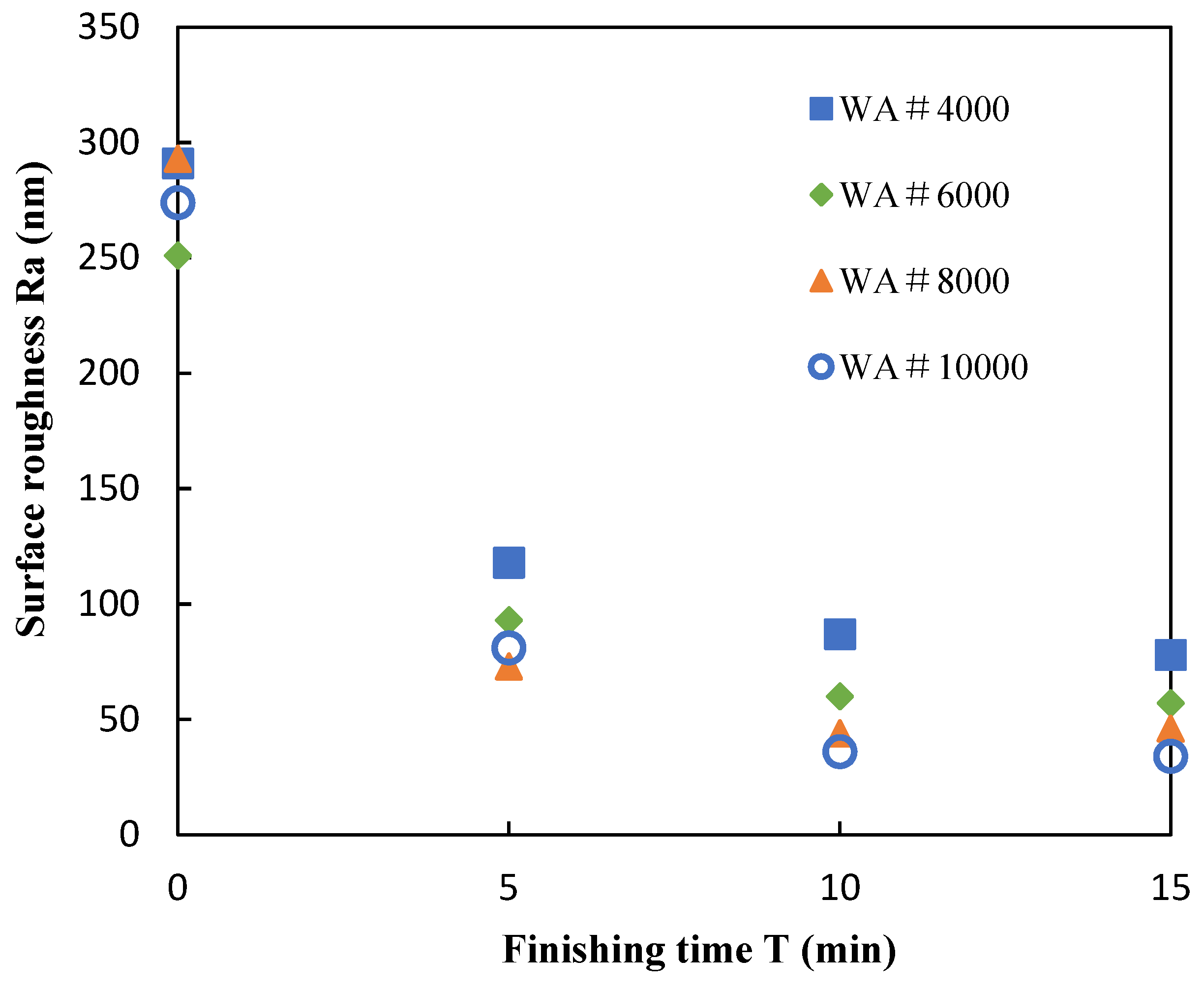
4.3. Abrasive Particle Size

In this experiment, we studied the influence of abrasive particle size on the finished surface. Figure 18 shows the change in surface roughness of the workpiece. When the working gap is 0.06 mm, the electrolytic iron powder with 30 µm in mean diameter is used, and the abrasive particle size is WA#10000, WA#8000, WA#6000, WA#4000, respectively. The experimental conditions are shown in Table 4. When the compound magnetic finishing fluid is subjected to a magnetic field, the magnetic particles in it are arranged according to the lines of magnetic force. The abrasive particles are held up by the iron powder and mixed with the iron powder to play the role of finishing the workpiece. Therefore, the state of abrasive particles has a vital influence on compound magnetic finishing fluid. When the size of the abrasive particles is large, it becomes difficult for the abrasive particles to be strongly supported by the iron powder. Abrasive particles cannot float on magnetic particles and cannot effectively perform finishing. Even if the excessively large abrasive particles float on the surface of the compound magnetic finishing fluid, due to the lack of strong support, the abrasive particles may roll when they contact the surface of the workpiece, which results in a weak finishing effect. In addition, larger abrasive particles may scratch the surface of the workpiece, which is not conducive to the improvement of surface quality. Abrasive particles of small particle size are less likely to scratch the surface of the workpiece, the finishing ability will also be weaker, and the finishing efficiency will also decrease. When the abrasive particles size is WA#10000, WA#8000, WA#6000, WA#4000, the corresponding final surface roughness is 34, 46, 57, and 78 nm, respectively. Among them, when WA#10000 is used, the final finishing effect is the best.

5. Conclusions

  • As the working gap decreases, the distribution width of compound magnetic finishing fluid on the conveyor belt becomes larger, and the area of the points of action on the workpiece in the finishing increases, the finishing force gradually increases, and a higher finishing efficiency is obtained. A smoother final surface is obtained when the working gap is 0.06 mm.
  • Compared with carbonyl iron powder of 3.4–4.5 µm in mean diameter, Electrolytic iron powder of 30 µm in mean diameter can obtain a smoother final surface and higher finishing efficiency under the current experimental conditions.
  • The best finishing quality is obtained when abrasive particles with a particle size of WA#10000 are used.
  • In this study, under the conditions of 30 µm in mean diameter, electrolytic iron powder, 0.06 mm working gap, and WA#10000 abrasive particles, the surface roughness of polychlorotrifluoroethylene resin plate was improved from 274 to 34 nm within 15 min.

Author Contributions

Conceptualization, J.X. and Y.Z.; methodology, J.X. and Y.Z.; validation, J.X. and H.X.; formal analysis, J.X.; investigation, J.X. and H.X.; data curation, J.X.; writing—original draft preparation, J.X. and H.X.; writing—review and editing, J.X.; project administration, Y.Z.; funding acquisition, Y.Z. All authors have read and agreed to the published version of the manuscript.

Funding

This research received no external funding.

Conflicts of Interest

The authors declare no conflict of interest.

References

  1. Shinmura, T.; Takazawa, K.; Hatano, E.; Aizawa, T. Study on magnetic-abrasive process: Process principle and finishing possibility. Bull. Jpn. Soc. Precis. Eng. 1985, 19, 54–55. [Google Scholar]
  2. Zou, Y.H.; Xie, H.J.; Zhang, Y.L. Study on surface quality improvement of the plane magnetic abrasive finishing process. Int. J. Adv. Manuf. Technol. 2020, 109, 1825–1839. [Google Scholar] [CrossRef]
  3. Xie, H.J.; Zou, Y.H. Investigation on finishing characteristics of magnetic abrasive finishing process using an alternating magnetic field. Machines 2020, 8, 75. [Google Scholar] [CrossRef]
  4. Zhang, J.; Wang, H.; Kumar, A.S.; Jin, M. Experimental and theoretical study of internal finishing by a novel magnetically driven polishing tool. Int. J. Mach. Tools Manuf. 2020, 153, 103552. [Google Scholar] [CrossRef]
  5. Kwak, J. Enhanced magnetic abrasive polishing of non-ferrous metals utilizing a permanent magnet. Int. J. Mach. Tools Manuf. 2009, 49, 613–618. [Google Scholar] [CrossRef]
  6. Jae-Seob, K. Mathematical model determination for improvement of surface roughness in magnetic-assisted abrasive polishing of nonferrous AISI316 material. Trans. Nonferrous Met. Soc. China 2012, 22, s845–s850. [Google Scholar]
  7. Kordonski, W.I.; Jacobs, S. Magnetorheological finishing. Int. J. Mod. Phys. B 1996, 10, 2837–2848. [Google Scholar] [CrossRef]
  8. Harris, D.C. History of magnetorheological finishing. In Window and Dome Technologies and Materials XII; International Society for Optics and Photonics: Bellingham, WA, USA, 2011; p. 80160N. [Google Scholar]
  9. Aurich, J.C.; Kirsch, B.; Setti, D.; Axinte, D.; Beaucamp, A.; Butler-Smith, P.; Yamaguchi, H. Abrasive processes for micro parts and structures. CIRP Ann. 2019, 68, 653–676. [Google Scholar] [CrossRef]
  10. Yamaguchi, H.; Graziano, A. Surface finishing of cobalt chromium alloy femoral knee components. CIRP Ann. 2014, 63, 309–312. [Google Scholar] [CrossRef]
  11. Graziano, A.A.; Ganguly, V.; Schmitz, T.; Yamaguchi, H. Engineering. Control of lay on cobalt chromium alloy finished surfaces using magnetic abrasive finishing and its effect on wettability. J. Manuf. Sci. Eng. 2014, 136, 031016. [Google Scholar] [CrossRef]
  12. Shinmura, T.; Takazawa, K.; Hatano, E.; Matsunaga, M.; Matsuo, T. Study on magnetic abrasive finishing. CIRP Ann. 1990, 39, 325–328. [Google Scholar] [CrossRef]
  13. Shinmura, T.; Takazawa, K.; Hatano, E. Study on Magnetic-Abrasive Process. Application to Edge Finishing. Bull. Jpn. Soc. Precis. Eng. 1985, 19, 218–220. [Google Scholar]
  14. Xie, H.; Zou, Y.H.; Dong, C.; Wu, J. Study on the magnetic abrasive finishing process using alternating magnetic field: Investigation of mechanism and applied to aluminum alloy plate. Int. J. Adv. Manuf. Technol. 2019, 102, 1509–1520. [Google Scholar] [CrossRef]
  15. Wu, J.; Zou, Y.H.; Sugiyama, H. Study on finishing characteristics of magnetic abrasive finishing process using low-frequency alternating magnetic field. Int. J. Adv. Manuf. Technol. 2016, 85, 585–594. [Google Scholar] [CrossRef]
  16. Zou, Y.H.; Shinmura, T. Study on internal magnetic field assisted finishing process using a magnetic machining jig. In Key Engineering Materials; Trans Tech Publications Ltd.: Stafa-Zurich, Switzerland, 2005; pp. 281–286. [Google Scholar]
  17. Yin, S.; Shinmura, T. Vertical vibration-assisted magnetic abrasive finishing and deburring for magnesium alloy. Int. J. Mach. Tools Manuf. 2004, 44, 1297–1303. [Google Scholar] [CrossRef]
  18. Yin, S.; Shinmura, T. A comparative study: Polishing characteristics and its mechanisms of three vibration modes in vibration-assisted magnetic abrasive polishing. Int. J. Mach. Tools Manuf. 2004, 44, 383–390. [Google Scholar] [CrossRef]
  19. Singh, D.K.; Jain, V.; Raghuram, V. Parametric study of magnetic abrasive finishing process. J. Mater. Process. Technol. 2004, 149, 22–29. [Google Scholar] [CrossRef]
  20. Jain, V.K.; Jayswal, S.C.; Dixit, P.M. Modeling and simulation of surface roughness in magnetic abrasive finishing using non-uniform surface profiles. Mater. Manuf. Process. 2007, 22, 256–270. [Google Scholar] [CrossRef]
  21. Mulik, R.S.; Pandey, P.M. Experimental investigations and modeling of finishing force and torque in ultrasonic assisted magnetic abrasive finishing. J. Manuf. Sci. Eng. 2012, 134, 051008. [Google Scholar] [CrossRef]
  22. Yamaguchi, H.; Shinmura, T.; Kobayashi, A. Development of an internal magnetic abrasive finishing process for nonferromagnetic complex shaped tubes. JSME Int. J. Ser. C Mech. Syst. Mach. Elem. Manuf. 2001, 44, 275–281. [Google Scholar] [CrossRef] [Green Version]
  23. Yamaguchi, H.; Shinmura, T. Takeo. Internal finishing process for alumina ceramic components by a magnetic field assisted finishing process. Precis. Eng. 2004, 28, 135–142. [Google Scholar] [CrossRef]
  24. Lee, Y.-H.; Wu, K.-L.; Jhou, J.-H.; Tsai, Y.-H.; Yan, B.-H. Two-dimensional vibration-assisted magnetic abrasive finishing of stainless steel SUS304. Int. J. Adv. Manuf. Technol. 2013, 69, 2723–2733. [Google Scholar] [CrossRef]
  25. Lee, Y.-H.; Wu, K.-L.; Bai, C.-T.; Liao, C.-Y.; Yan, B.-H. Planetary motion combined with two-dimensional vibration-assisted magnetic abrasive finishing. Int. J. Adv. Manuf. Technol. 2014, 76, 1865–1877. [Google Scholar] [CrossRef]
  26. Kala, P.; Pandey, P.M.; Verma, G.C.; Sharma, V. Understanding flexible abrasive brush behavior for double disk magnetic abrasive finishing based on force signature. J. Manuf. Process. 2017, 28, 442–448. [Google Scholar] [CrossRef]
  27. Kala, P.; Sharma, V.; Pandey, P.M. Surface roughness modelling for double disk magnetic abrasive finishing process. J. Manuf. Process. 2017, 25, 37–48. [Google Scholar] [CrossRef]
  28. Xu, J.; Zou, Y. Development of a new magnetic abrasive finishing process with renewable abrasive particles using the circulatory system. Precis. Eng. 2021, 72, 417–425. [Google Scholar] [CrossRef]
  29. Shinmura, T.; Aizawa, T. Study on internal finishing of a non-ferromagnetic tubing by magnetic abrasive machining process. Bull. Jpn. Soc. Precis. Eng. 1989, 23, 37–41. [Google Scholar]
  30. Aouici, H.; Yallese, M.A.; Chaoui, K.; Mabrouki, T.; Rigal, J.F. Analysis of surface roughness and cutting force components in hard turning with CBN tool: Prediction model and cutting conditions optimization. Measurement 2012, 45, 344–353. [Google Scholar] [CrossRef]
Figure 1. Schematic of the processing principle. Reprinted from Precision Engineering, 72, Xu J, Zou Y, Development of a new magnetic abrasive finishing process with renewable abrasive particles using the circulatory system, Pages No. 417-425, Copyright (2021), with permission from Elsevier.
Machines 09 00195 g001
Figure 2. The schematic diagram of experimental device. Reprinted from Precision Engineering, 72, Xu J, Zou Y, Development of a new magnetic abrasive finishing process with renewable abrasive particles using the circulatory system, Pages No. 417-425, Copyright (2021), with permission from Elsevier.
Machines 09 00195 g002
Figure 3. Sectional view and a partial enlarged view of the finishing wheel. Reprinted from Precision Engineering, 72, Xu J, Zou Y, Development of a new magnetic abrasive finishing process with renewable abrasive particles using the circulatory system, Pages No. 417-425, Copyright (2021), with permission from Elsevier.
Machines 09 00195 g003
Figure 4. Magnetic field distribution in the direction of conveyor belt movement.
Machines 09 00195 g004
Figure 5. The status of the compound magnetic finishing fluid in the different area.
Machines 09 00195 g005
Figure 6. Magnetic field distribution in the width direction of the conveyor belt.
Machines 09 00195 g006
Figure 7. Simulation result of magnetic field vector direction.
Machines 09 00195 g007
Figure 8. Schematic diagram of force measurement system.
Machines 09 00195 g008
Figure 9. Measurement waveform (polychlorotrifluoroethylene resin plate, working gap 0.1 mm).
Machines 09 00195 g009
Figure 10. Measured finishing force.
Machines 09 00195 g010aMachines 09 00195 g010b
Figure 11. External view of the experimental device.
Machines 09 00195 g011
Figure 12. Effects of iron powder particle size on surface roughness.
Machines 09 00195 g012
Figure 13. 3D surface morphology before and after finishing with different iron powder size. (a) Electrolytic iron powder of 30 µm in mean diameter; (b) Carbonyl iron powder, 3.4–4.5 µm in mean diameter.
Machines 09 00195 g013
Figure 14. Schematic diagram of finishing area observation.
Machines 09 00195 g014
Figure 15. States of the compound magnetic finishing fluid in the finishing area with different working gaps.
Machines 09 00195 g015
Figure 16. States of compound magnetic finishing fluid leaving the finishing area with different working gaps.
Machines 09 00195 g016
Figure 17. Effects of working gap on surface roughness.
Machines 09 00195 g017
Figure 18. Effects of abrasive particle size on surface roughness.
Machines 09 00195 g018
Table 1. Measuring conditions.
ParameterCondition
Magnetic particlesElectrolytic iron powder, 30 µm in mean diameter: 141 g
Cutting fluidWater-soluble cutting fluid, SCP-23: 62 mL
Working gap0.06 mm, 0.1 mm
AbrasivesWA#10000: 16 g
Conveyor belt linear speed150 mm/s
WorkpiecePolychlorotrifluoroethylene resin plate with the size of 100 × 100 × 6 mm
SUS304 stainless steel plate with the size of 100 × 100 × 1 mm
Flow rate19 mL/min
Table 2. Experimental conditions.
ParameterCondition
Magnetic particlesType 1: Carbonyl iron powder, 3.4–4.5 µm in mean diameter: 141 g Type 2: Electrolytic iron powder, 30 µm in mean diameter: 141 g
Cutting fluidWater-soluble cutting fluid, SCP-23: 62 mL
Working gap0.06 mm
AbrasivesWA#10000: 16 g
Conveyor belt linear speed150 mm/s
WorkpiecePolychlorotrifluoroethylene resin plate with the size of 100 × 100 × 6 mm
Feed speed of workpiece120 mm/min
Flow rate19 mL/min
Finishing time15 min
Table 3. Experimental conditions.
ParameterCondition
Magnetic particlesElectrolytic iron powder, 30 µm in mean diamete: 141 g
Cutting fluidWater-soluble cutting fluid, SCP-23: 62 mL
Working gap0.06 mm, 0.1 mm, 0.14 mm
AbrasivesWA#10000: 16 g
Conveyor belt linear speed150 mm/s
WorkpiecePolychlorotrifluoroethylene resin plate with the size of 100 mm × 100 mm × 6 mm
Feed speed of workpiece120 mm/min
Flow rate19 mL/min
Finishing time15 min
Table 4. Experimental conditions.
ParameterCondition
Magnetic particlesElectrolytic iron powder, 30 µm in mean diamete: 141 g
Cutting fluidWater-soluble cutting fluid, SCP-23: 62 mL
Working gap0.06 mm
AbrasivesType 1: WA#10000: 16 g
Type 2: WA#8000: 16 g
Type 3: WA#6000: 16 g
Type 4: WA#4000: 16 g
Conveyor belt linear speed150 mm/s
WorkpiecePolychlorotrifluoroethylene resin plate with the size of 100 × 100 × 6 mm
Feed speed of workpiece120 mm/min
Flow rate19 mL/min
Finishing time15 min
Publisher’s Note: MDPI stays neutral with regard to jurisdictional claims in published maps and institutional affiliations.

