Article

Kineto-Static Analysis and Design Optimization of a 3-DOF Wrist Rehabilitation Parallel Robot with Consideration of the Effect of the Human Limb †

Department of Mechanical Engineering, Tokyo Institute of Technology, Tokyo 152-8550, Japan
*
Author to whom correspondence should be addressed.
This paper is an extended version of our paper published in Liu, Y.-C.; Takeda, Y. Analysis of a 3-DOF Parallel Robot for Wrist Rehabilitation with Consideration of Effect of Human Limb. In Proceedings of the 26th Jc-IFToMM Symposium, 3rd International Jc-IFToMM Symposium, 19 March 2021.
Machines 2021, 9(12), 323; https://doi.org/10.3390/machines9120323
Submission received: 13 October 2021 / Revised: 21 November 2021 / Accepted: 24 November 2021 / Published: 28 November 2021
(This article belongs to the Special Issue Advances of Japanese Machine Design)

Abstract

:
When designing rehabilitation robots, there remains the challenge of ensuring the comfort and safety of users, especially for wearable rehabilitation robots that interact with human limbs. In this paper, we present a kineto-static analysis of the 3-RPS parallel wrist rehabilitation robot, taking into account the soft characteristics of the human limb and its kinematic mobility. First, the human upper-limb model was made to estimate the interaction force and moment through inverse kinematic analysis. Second, a static analysis was conducted to obtain the force and moment acting on the human limb, which is directly related to the user’s comfort and safety. Then, the design parameters of the 3-RPS robot were obtained by generic optimization through kineto-static analysis. Finally, the influence of the parasitic motion of the 3-RPS robot and the initial offset between the wrist center and the robot moving platform were discussed. Through the analysis results, we provide effective solutions to ensure the safety and comfort of the user.

1. Introduction

For post-stroke patients who suffer from loss of upper limb motor ability, it is difficult for them to live independently, especially as the function of the wrist is highly related to performing many basic activities of daily living (ADL). Rehabilitation is usually the main treatment, including intensive and task-based exercises that allow the patient to regain their lost motor function. Conventional rehabilitation therapy requires the patient to be treated by well-trained clinicians, so its effectiveness is limited due to the lack and exhaustion of therapists. Fortunately, with the development of robot-assisted therapy, the impaired limb can be effectively recovered through repetitive and intensive treatment, therefore overcoming the limitations of traditional therapy [1]. However, incorporating robots into a long rehabilitation process may raise the risk for the patient during rehabilitation, especially for stroke patients with motion disabilities who may easily be injured during interaction with the robot. Therefore, ensuring the user’s comfort and safety has always been one of the most important issues for rehabilitation robot design, especially for wearable rehabilitation robots.
One of the possible risks during rehabilitation is that human limbs are fixed to the rehabilitation robot through cuffs or straps, and thus contact between the human body and the robot is unavoidable. Wearable rehabilitation robots usually have multiple positions connected to the user’s limb, and transfer loads to the user through these attachments. Due to the soft and deformable characteristics of human skin and tissues, the interface between the human body and the robot is easily deformed. As a result of the deformation, unwanted forces are generated, which may cause discomfort to the user or even reduce the therapeutic effect due to the deformation and slippage of the cuff. Although the cuffs are generally designed to have a larger contact area around the limb to reduce the contact pressure, due to the repetitive rehabilitation movements, if the unwanted force continues to apply on the sensitive skin, it can still easily cause discomfort or pain to the user. Therefore, it is necessary to fully understand the movements of the attachment and interaction forces between humans and robots to reduce these negative effects [2,3].
Numerous rehabilitation robots have been proposed in the last four decades for restoring patients’ wrist movement ability [4,5,6,7,8]. According to the different structures, these can be divided into two types: serial robots and parallel robots. Serial robots have a larger workspace and are designed in a more intuitive way to provide assistive torques for human joints. Also, due to their relatively smaller size and simpler kinematics, they have been widely used in the field of rehabilitation. Compared with serial robots, parallel robots have some appealing mechanical features such as a relatively stable performance within the entire workspace and smaller configuration changes according to movement, which are a benefit to users’ safety. In addition, with excellent position accuracy, greater payload capacity, and higher stiffness, parallel robots are considered as a good candidate with better rehabilitation capabilities. They usually have at least two degrees of freedom (DOFs) for wrist movements in flexion/extension (FE) and radial/ulnar deviation (RUD) movements, some of which can achieve pronation/supination (PS) movements of the forearm [2,3]. In addition, lower-mobility parallel robots have attracted much attention in recent years. They have less than 6 DOFs, thereby reducing the linkages and actuators needed to perform the required tasks while reducing costs and having a simpler structure for home rehabilitation. However, despite the ongoing increase of research in this field, the discussion of incorporating human limbs into the design of robotic systems is insufficient. Due to the softness of human tissue, their deformation cannot be avoided. Including the human limb into the design process is necessary to provide solutions for comfort and safety. The design of the attachment, including passive mechanisms to connect the robotic link to the user, as presented in [9], indicates that the applied forces and moments of the cuff can cause discomfort and even injury. In [10], different joint misalignment compensation strategies have been discussed. The comfort of the user is especially important since it may result in the disuse of the robot even for a robot with good performance. In our previous works, we conducted the analysis of a 1-DOF wrist rehabilitation robot with compliant elements and additional passive joints [11]. The deformation of the human limb causing the movement of the cuff results in reducing the angular range of the wrist. In addition, modeling human soft tissue as a passive joint in a wearable robot may achieve compactness with an acceptable level of comfort [12]. To make a safe rehabilitation robot that patients are willing to use, it is crucial to understand the behavior of human tissues during the rehabilitation process, which is directly related to the safety and comfort of the users.
The present paper is an extended version of the research described in [13]. It addresses the kineto-static analysis of a 3-RPS parallel wrist rehabilitation robot with consideration of the soft characteristics of the human limb. Herein, R, P, and S denote a revolute joint, an actuated prismatic joint, and a spherical joint, respectively. First, the kinematic analysis of the 3-RPS parallel robot is examined and the parasitic motions of the 3-RPS are calculated. In addition, by including the human limb into the robot design, the attachment of the forearm is modeled as a complex joint [14] due to its soft and deformable property, which has four degrees of freedom composed of three prismatic joints and one revolute joint (3P1R). Then, the deformation of human tissue and the attachment can be obtained. Also, the interaction forces and torques on the human limb can be estimated by assuming that the soft tissues of the human limb have a spring-like behavior. Although the design of rehabilitation robots requires consideration of many aspects, such as performance, low cost, volume, and wearable convenience, this paper focuses on ensuring comfort and safety which, are essential for the patient’s willingness to use the rehabilitation robot. We extend our previous work by optimization design through kineto-static analysis, in order to minimize the forces and moments of the human limbs. The analysis results contribute to providing beneficial ideas for the user’s comfort and safety in the use of the wearable rehabilitation robot.

2. Methods

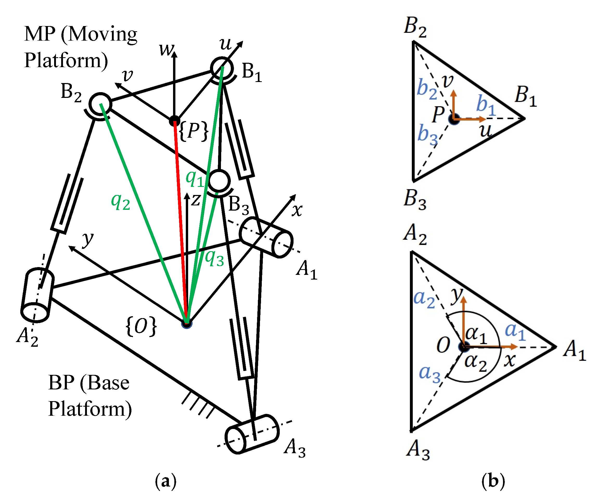
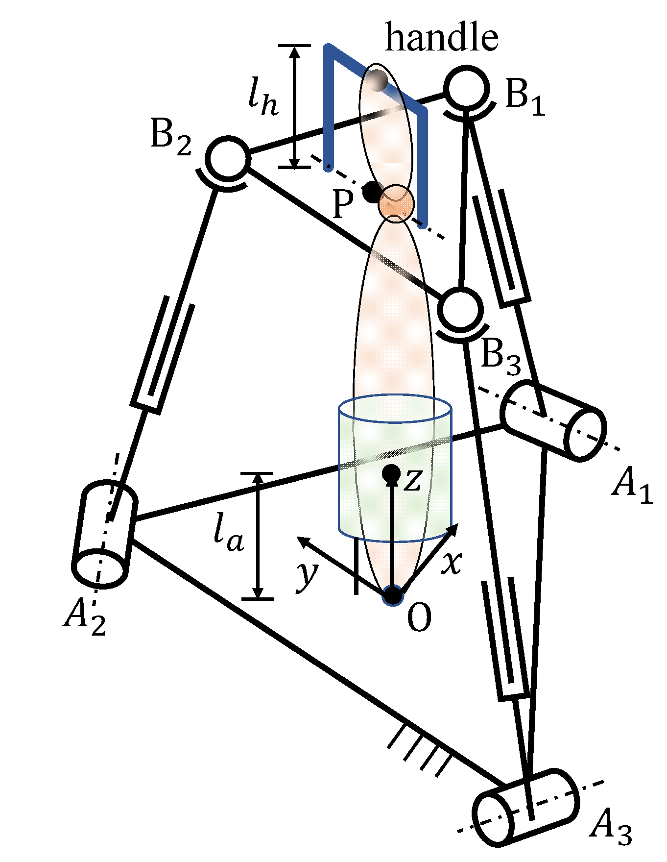
2.1. Position Analysis of a Wrist Rehabilitation Robot

The spatial 3-RPS parallel robot used for wrist rehabilitation is illustrated in Figure 1. The robot consists of a moving platform (MP) which is connected to a fixed base platform (BP) by three identical limbs. Each limb is composed of a revolute joint (R), a prismatic joint (P), and a spherical joint (S) in sequence from BP to MP, and the joints of BP and MP are placed at the vertices of the triangle platforms, as shown in Figure 1a. The prismatic joint is actuated by a linear actuator, while the other joints are passive. The 3-RPS robot is a lower-mobility parallel robot, which can perform two rotations and one translation. Three parasitic motions occur during the movement in the constrained DOFs, including one rotation about the z-axis and two translations along the x- and y-axes. The robot is used for wrist rehabilitation to achieve hand flexion/extension movement and radial/ulnar deviation. Since rehabilitation only requires two DOFs and the translation in the z-axis is not considered in this paper, the use of a lower-mobility parallel robot can reduce the number of linkages and actuators, thereby reducing the cost and weight of the robot, which is suitable for in-home rehabilitation. We considered the range of motion (ROM) of the wrist joint, which ranges from −50° to 50° for the flexion/extension movement and from −30° to 30° for the ulnar/radial deviation of the hand. As shown in Figure 2, the wrist joint is simplified as a universal joint with two DOFs as rotating about x w and y w axes at the center of the wrist O w .
The coordinate system of the fixed BP is represented by O-xyz at the centroid of the platform A1A2A3. Ai represents the location of the R joint of the BP, while Bi represents the location of the S joint on the MP. The x-axis lies in the BP plane and points to point A1. Correspondingly, the MP frame is denoted by P-uvw at the centroid of the platform B1B2B3. The u-axis lies in the MP plane and passes through point B1. The radii of the triangular circumscribed circle of the BP and MP are a and b, respectively. The angles between O A 1 ( P B 1 ) and O A 2 ( P B 2 ) , O A 1 ( P B 1 ) and O A 3 ( P B 3 ) are denoted by α 1 and α 2 , respectively, as shown in Figure 1. The axes of the revolute joint are coplanar with BP and the direction of the ith revolute joint axis is perpendicular to O A i . Also, the ith prismatic joint axis is perpendicular to the direction of the ith revolute joint axis. In the corresponding coordinate system, the position vectors of the vertices of BP and MP can be expressed as follows:
O A 1 = a 1 = [ a 0 0 ] T O A 2 = a 2 = [ cos ( α 1 ) · a sin ( α 1 ) · a 0 ] T   O A 3 = a 3 = [ cos ( α 2 ) · a sin ( α 2 ) · a 0 ] T
P B 1 = b 1 = [ b 0 0 ] T P B 2 = b 2 = [ cos ( α 1 ) · b sin ( α 1 ) · b 0 ] T P B 3 = b 3 = [ cos ( α 2 ) · b sin ( α 2 ) · b 0 ] T
The orientation of the MP can be described by using a Z-X-Y type Euler angle ( ψ , θ , ϕ ) with respect to the fixed coordinate system, and the rotation matrix is
R P O = R o t ( y , θ ) · R o t ( x , ψ ) · R o t ( z , ϕ ) = [ c θ c ϕ + s ψ s θ s ϕ c θ s ϕ + s ψ s θ c ϕ c ψ s θ c ψ s ϕ c ψ c ϕ s ψ s θ c ϕ + s ψ c θ s ϕ s θ s ϕ + s ψ c θ c ϕ c ψ c θ ] = [ u x v x w x u y v y w y u z v z w z ]
where s and c correspond to sine and cosine functions, respectively.
As depicted in Figure 1, the position vector of the MP vertices with respect to the BP coordinate can be written as
O B i = O P + P B i , i = 1 ,   2 ,   3
Then, Equation (4) can be written as
q i = [ P x P y P z ] T + R P O · b i u v w , i = 1 ,   2 ,   3
Substituting Equations (2) and (3) into Equation (5) yields
q 1 = [ P x + b · u x P y + b · u y P z + b · u z ] q 2 = [ P x + b · cos ( α 1 ) · u x + b · sin ( α 1 ) · v x P y + b · cos ( α 1 ) · u y + b · sin ( α 1 ) · v y P z + b · cos ( α 1 ) · u z + b · sin ( α 1 ) · v z ] q 3 = [ P x + b · cos ( α 2 ) · u x + b · sin ( α 2 ) · v x P y + b · cos ( α 2 ) · u y + b · sin ( α 2 ) · v y P z + b · cos ( α 2 ) · u z + b · sin ( α 2 ) · v z ]
Due to the constraint of the revolute joint, the limb can only move in the limb plane. We can obtain the following constraints equations:
[ q 1 ] y = 0 [ q 2 ] y = sin ( α 1 ) cos ( α 1 ) · [ q 2 ] x [ q 3 ] y = sin ( α 2 ) cos ( α 2 ) · [ q 3 ] x
Here, to simplify the problem, we set the angle for the arrangement of R joints as | α 1 | = | α 2 | = α . Finally, we set the output motions of 3-RPS, including the rotations about the x- and y-axes, ψ and θ , and translation along the z-axis, P z , as output motion parameters. To obtain the parasitic motions of 3-RPS, which are one rotation about the z-axis and two translations along the x- and y-axes, by using Equations (3), (6), and (7), the equations describing the parasitic motions of 3-RPS can be derived as
P x = b · cos α · ( c θ c ϕ + s ψ s θ s ϕ c ψ c ϕ ) P y = b c ψ s ϕ ϕ = tan 1 ( s ψ s θ c ψ + c θ )
The parasitic motions of the lower-mobility parallel robot are the unwanted motions in the constrained DOF, which is considered to be detrimental to many applications, and its impact cannot be ignored.

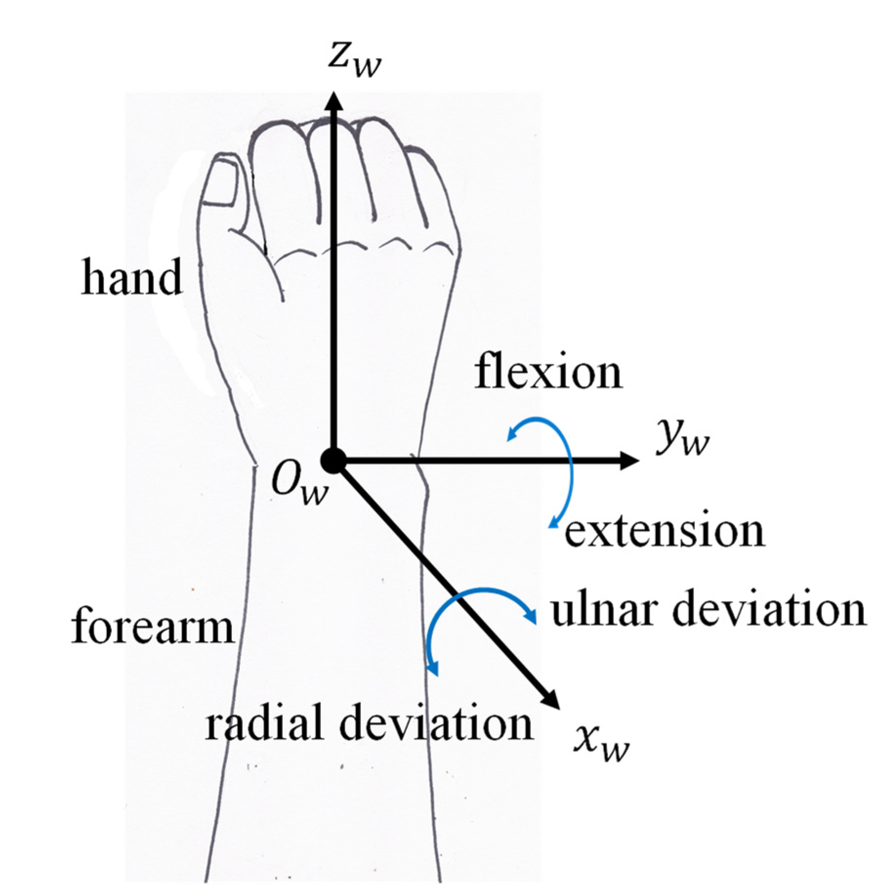
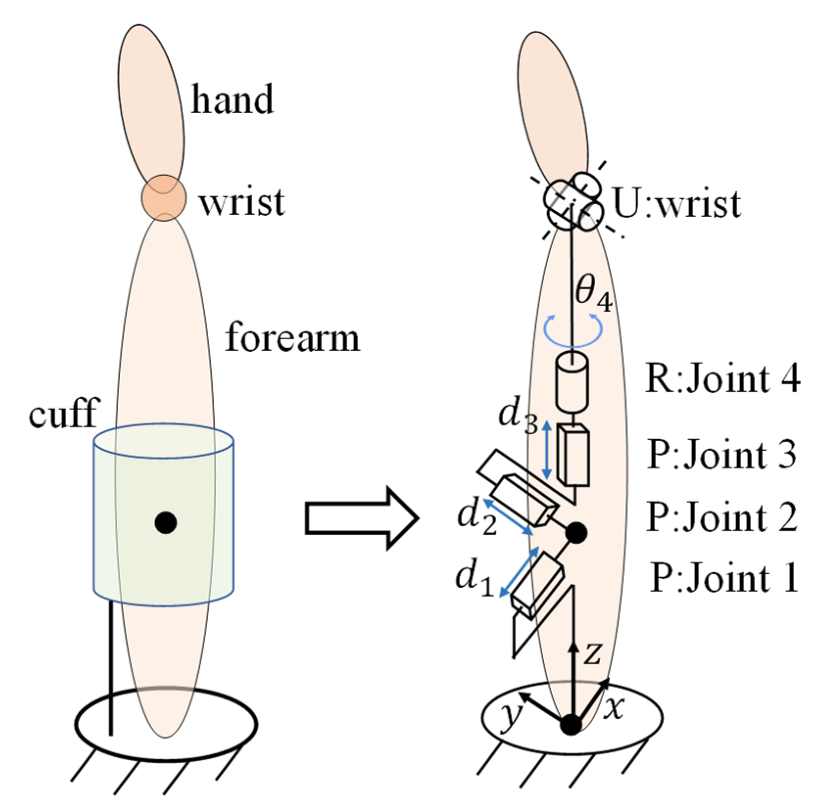
2.2. Inverse Kinematic Analysis of the Human Limb

The conceptual diagram of the human limb with the 3-RPS robot can be seen in Figure 3. The proximal end of the forearm is attached to the BP of the 3-RPS robot by the cuff and the hand is firmly fixed to the handle. The handle height ( l h ) is set as 80 mm. The distance from the fixed origin O to the center of the cuff ( l a ) is set as 50 mm. Because of the soft and deformable nature of human tissue, the cuff can have up to 6 DOFs, including 3 degrees of rotational freedom and 3 degrees of translational freedom. In order to simplify the problem, here we describe the attachment part as a complex joint [14] consisting of three prismatic joints and one revolute joint, as illustrated in Figure 4. Moreover, the wrist joint is regarded as a universal joint for conducting FE and RUD hand movements. We used the following assumptions in the analysis presented in this paper:
  • The hand is securely attached to the handle, and the finger effects are ignored throughout the motion.
  • The cuff is tightly fastened to the forearm, with no slippage.
  • The dynamic impact on the robot will not be considered.
Based on the assumptions stated above, the human limb model is comprised of three prismatic joins, one revolute joint, and one universal joint, as shown in Figure 4. It is worth mentioning that the hand is considered to be attached to the handle of the MP, so that if the pose of the 3-RPS is described, the three angular parameters and three position parameters of the MP are known. Then, we can simply derive the position of the center of the wrist joint and the orientation of the hand. As a result, this issue can be considered as solving the inverse kinematics of an open chain (PPPRRR) with 6 DOFs, which is the defined human limb model. Inverse kinematic problems can be solved numerically using a variety of procedures. To calculate the inverse kinematics, we used the iterative Newton–Raphson method conducted in [15]. To begin, the product of exponentials (PoE) formula for forward kinematics is as follows:
T s b ( θ ) = e [ S 1 ] θ 1 e [ S 2 ] θ 2 e [ S 3 ] θ 3 e [ S 4 ] θ 4 e [ S 5 ] θ 5 e [ S 6 ] θ 6 M
where S n = ( ω i , ν i ) represents the screw axis along joint i, θ i denotes the joint i variables, and M is the position and orientation of the end-effector at the home position of the limb. Then, the twist in the end-effector frame V b can be represented by using the matrix logarithm:
[ V b ] = log ( T s b 1 ( θ i ) T s d )
In addition, the twist in the fixed frame V s can be obtained by adjoint representation [ A d T ] :
V s = [ A d T s b ] V b
When we give a desired end-effector configuration in space frame T s d and an initial guess θ 0 6 , the iteration form can be expressed as follows:
θ i + 1 = θ i + J s ( θ i ) V s
where i denotes the number of iterations and J s denotes the Jacobian matrix.
The iteration algorithm tries to find the joint variables until it reaches the target configuration with a small tolerance for the position and orientation of the end-effector, which are set as 10 4 m and 10 3 rad, respectively. Then, we can obtain the approximate solution that is closest to the initial guess.

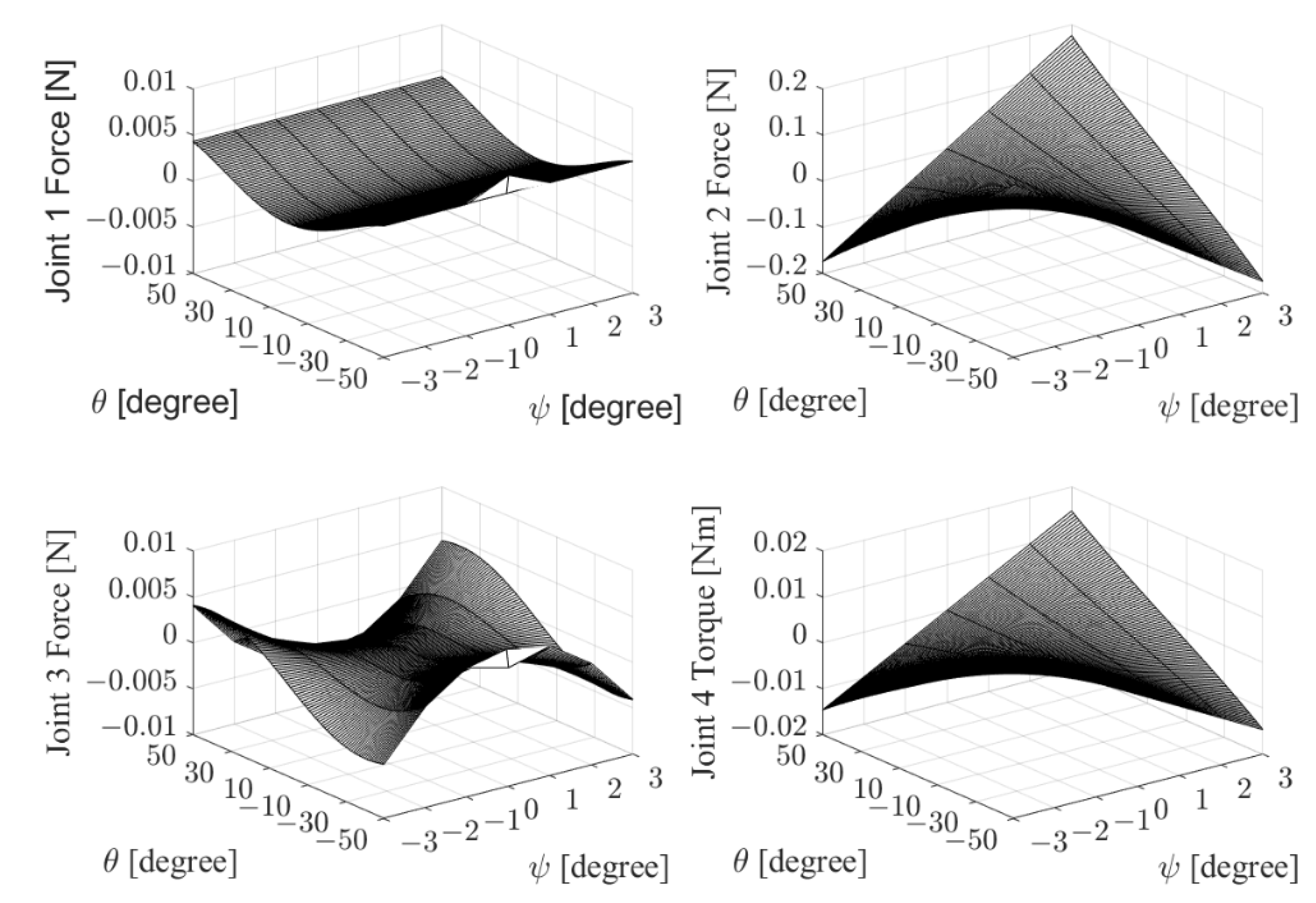
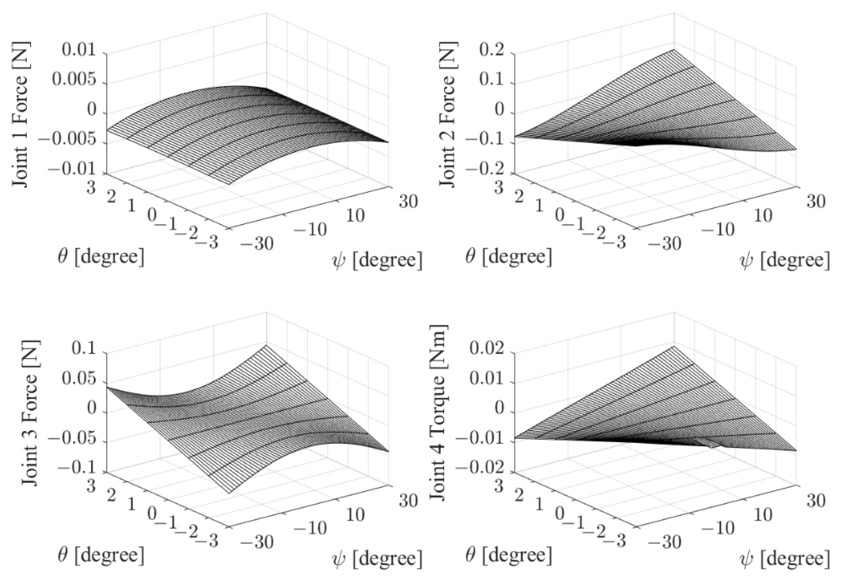
2.3. Analysis of Unwanted Forces at the Interface between the Human and Robot

The notion of a dynamic pair [16] is used to model the connection parts between the human and robot with the specified type of movement and mechanical properties. Considering the human body’s deformability and softness, the forearm tissue can be considered as having a spring-like behavior. The forces and the torque are expected to be applied since we model the forearm tissue as a complex joint composed of three prismatic joints and one revolute joint. It is vital to note that the spring coefficient of the forearm may change as a non-linear spring element and will rise dramatically when approaching the limit of the deformation range. In this case, we simply analyze the smooth motion of the soft tissue and assume that it satisfies the linear relationship between the applied force/torque and the amount of deformation. The translational and rotational spring coefficients of the forearm found in the literature could vary due to varied measurement conditions and here they are set as 143 N/m and 0.6 Nm/rad, respectively [17]. Then, the force and torque can be calculated as follows:
F x = k t · d 1 F y = k t · d 2 F z = k t · d 3 M z = k r · θ 4
where d represents the displacement of the prismatic joint, θ represents the angle of the revolute joint, and k t , k r denote the translational and rotational spring constants, respectively.

2.4. Static Analysis of the Human Limb with the 3-RPS Robot

In the above analysis, we only performed a kinematic analysis on the robot with the human limb. In other words, no external forces were considered. Here, in order to have a better understanding of the interaction between the robot and the human limb during the rehabilitation process, we conduct a static analysis of the robot with the human limb. First, according to our assumptions, the elbow of the human limb is attached to the table, and the hand is firmly fixed to the handle of the MP. Therefore, we can regard the human limb as an open chain, while the external force is applied to the hand by the robot. Although the maximum torque for hand FE and RUD motions in daily living is about 0.35 N∙m according to several studies [5,6], for patients who need rehabilitation, their joints usually have more resistance to joint movement due to injury, inflammation, and so on. Therefore, the external torque (Tout) is set as 1.2 N∙m in this paper.
Then, considering that the human limb is in a static equilibrium, we can use the following equation:
τ = J T ( θ )
where τ is the joint force/torques, J is the Jacobian matrix, and is the external wrench. When an external wrench is applied to the human hand by the robot and keeping the human limb at an equilibrium state, we can use Equation (14) to calculate the joint force/torque of the human limb to create an opposing wrench . The obtained force/torque of the human limb, which needs to be minimized, is related to the comfort and safety of the user.

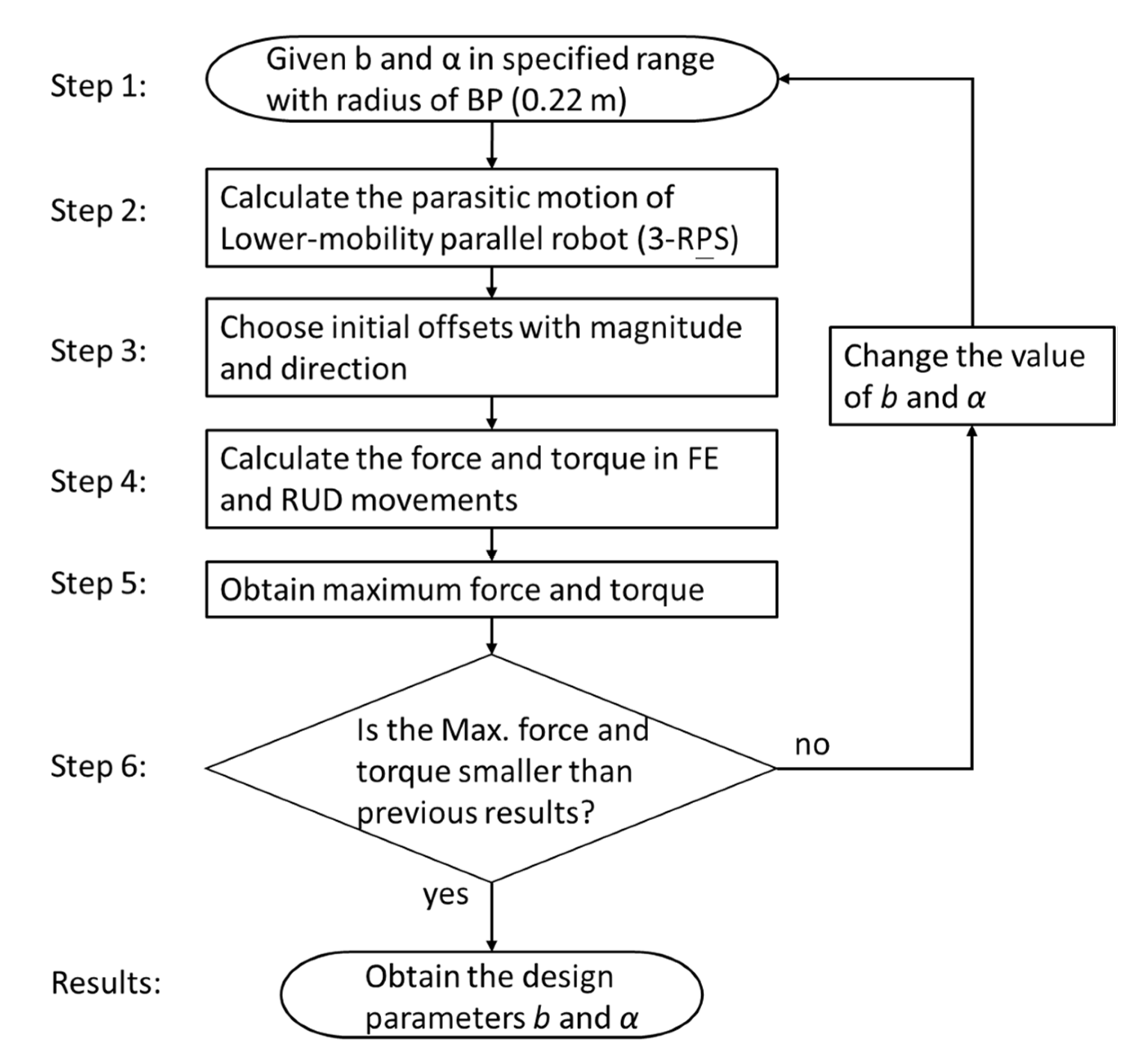
2.5. Multi-Objective Optimization

As stated earlier, we expect the analyzed joint force/torque of the human limb to be minimized in order to ensure the comfort and safety of the user. In this section, the genetic algorithm (GA) proposed by Holland et al. [18] is applied to determine the value of the design variables. The GA is a useful optimization method inspired by evolution and natural selection. Its purpose is to find the maximum or minimum value of a given objective function   f ( x ) where x = { x i | i = 1 ,   2 ,   ,   N } . Through several evolutionary-inspired processes such as inheritance, selection, mutation, and crossover, we can efficiently examine the search space and obtain solutions while avoiding falling into local optimal solutions. Thus, this method is capable of obtaining the global optimal solution to solve the optimization problem.
According to the analysis results in [13], the parasitic motions of the 3-RPS robot led to the generation of force/torque. Therefore, from Equations (7) and (8), we can choose these design parameters related to the parasitic motion, including the radius of MP, b, and the arrangement of the revolute joints, which are governed by the angles α 1 and α 2 . As mentioned above, here, we set the angle for the arrangement of R joints as | α 1 | = | α 2 | = α for simplicity.
When there are multiple objective functions, which are related to most of the problems in real life, we need to apply a multi-objective optimization method. The GA is well suited to solve multi-objective optimization for the optimized design parameters of the robot. A tradeoff is often needed between these objective functions. Therefore, we cannot simply obtain the best solution for comparison with each other; we can only obtain the Pareto optimal solution, that is, a set of solutions between certain objectives that conflict with each other. The multi-objective optimization functions are expressed in the following equations:
minimize P ( X ) = min [ f 1 ( X ) ,   f 2 ( X ) ] f 1 ( X ) = i = 1 n max { | F j |   : j = 1 . . m } f 2 ( X ) = i = 1 n max { | τ j |   : j = 1 . . m } X = [ b ,   α ] subject   to   0.05 b 0.15 , 90 ° α 170 °
where X is the vector of design parameters to be optimized. Here, the radius of MP, b, is set in a range from 0.05 m to 0.15 m, considering the acceptable size of the rehabilitation robot. Also, the angle α is set in the range from 90° to 170°. Obviously, the angle α close to 180° is an unreasonable arrangement. For the objective functions, n is the number of data sets and m is the number of analyzed data, and f 1 ( X ) , f 2 ( X ) are the sum of the maximum absolute value of the joint forces and joint torques, respectively. Our reason for choosing the absolute maximum value is that the values of forces and torques acting on the human limb should be relatively small and avoid a peak of force or torque during the rehabilitation, which is directly related to causing discomfort or may even result in injury to the user. The selected GA parameters are shown in Table 1. The optimization process is calculated by the multi-objective functions provided in the MATLAB optimization toolbox. The flowchart of the analysis procedure mentioned above is presented in Figure 5.

3. Results and Discussion

3.1. Kineto-Static Analysis and Optimization Design

In this section, we focus on the results of optimized design by performing kineto-static analysis. According to our previous research of a 3-RPS kinematics analysis, two factors that may affect the force and torque exerted on the human limb have been discussed [13]. The first is the parasitic motion of the 3-RPS robot, and the second is the initial offset between the wrist joint and the center of the MP. Hence, when solving the optimization problem, we have to consider these two factors. The parasitic motion of 3-RPS is relatively intuitive and can be obtained by using Equation (8). The analysis mainly focuses on FE and RUD movements, while considering the angular error existing in actual use. Here, we set the scope of the analysis as the following two ranges: (1) θ = −50° to 50° and ψ = −3° to 3° for FE movement and (2) ψ = −30° to 30° and θ = −3° to 3° for RUD movement. For the initial offsets, we consider an offset as 5 mm along the x-, y-, and z-axis in both positive and negative directions. There are six cases with offsets in six directions, plus one case without an offset, so that there are a total of seven sets of calculations for each movement. The main reason for considering the offsets is that it is difficult to have a perfect adjustment to ensure that the center of the wrist and the center of the MP can be consistent when the robot is connected to the user limb. The Pareto optimal solutions with the corresponding objective function values are shown in Table 2, and the results have also been verified through the equilibrium equations mentioned in Section 2.
It can be seen from the results that the optimal solutions of the radius of the MP change within a specific range, that is, b ∈ [0.050, 0.085] (m), while all the values of the optimized angle α are close to 90°. These optimization results show that the arrangement of revolute joints is suitable for 90° to achieve the objective goal of reducing the maximum force and torque exerted on the human limb. However, the relationship between the initial offsets and maximum force/torque for FE and RUD movements is not clear. Here, although the maximum absolute torque is relatively large, we choose the candidate with a structural parameter set, = [0.05, 90.15°], which has the smallest maximum absolute force. The analyzed results are discussed in the next section.

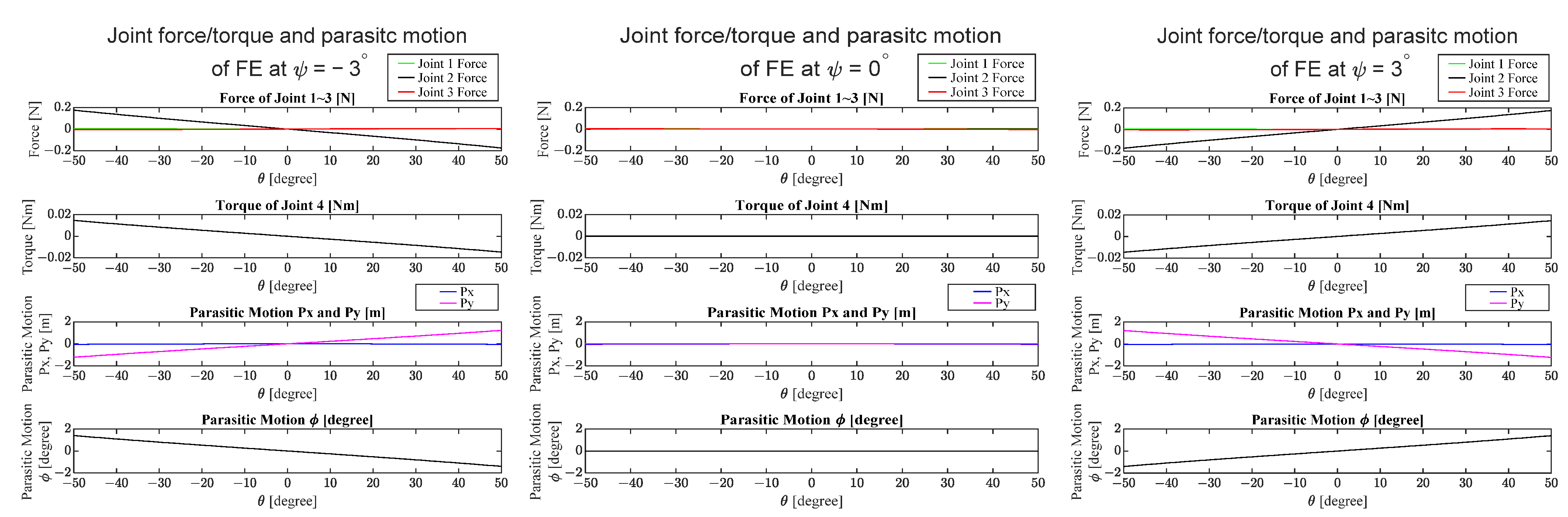
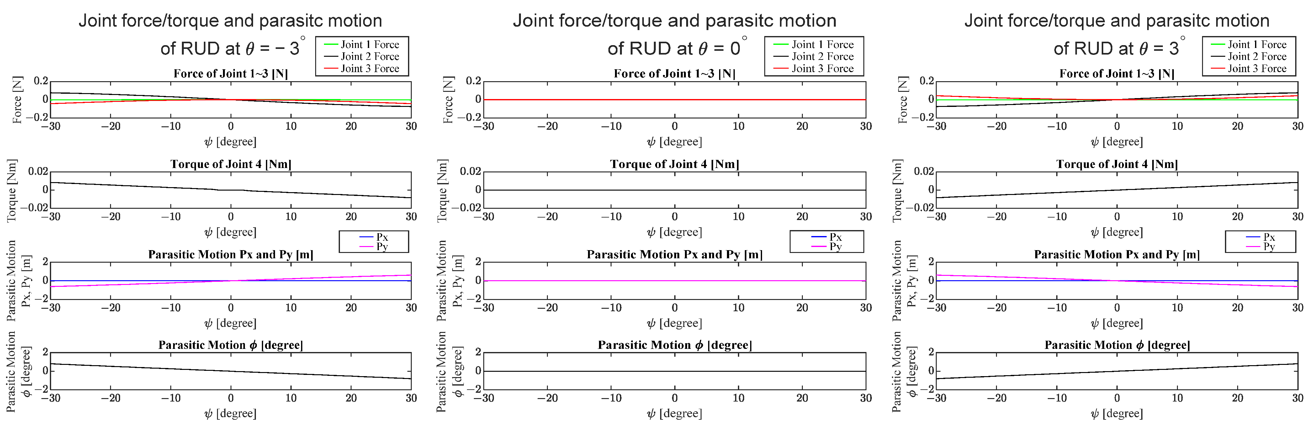
3.2. Kineto-Static Analysis of the Candidate Design

In this section, the present analysis method is applied to the 3-RPS parallel robot with the candidate design parameters to estimate the force and torque applied to the forearm. The structural parameters of the 3-RPS robot are shown in Table 3. It is worth noting that the radius of BP does not affect the value of the parasitic motion of 3-RPS from Equation (8). Although the radius of the BP can affect the size and stability of the robot, here we set the radius of the BP as 0.22 m for the analysis. Moreover, the initial distance between the BP and MP is set as 0.25 m, which corresponds to the average length of the human forearm between the elbow and wrist joint [19].
The results of the parasitic motion analysis are shown in Figure 6. We can find that the parasitic motion in the x-direction is close to zero, and the parasitic motions in the y-direction and around the z-axis are changed according to the angle θ and ψ . In this section, we focus on the FE and RUD movements with a certain angular error in the range of θ = −50° to 50° and ψ = −3° to 3° for FE movement and in the range of ψ = −30° to 30° and θ = −3° to 3° for RUD movement.
First, we only consider the influence of the parasitic motion of 3-RPS, assuming that the center of the wrist joint coincides with the center of the MP. By the inverse kinematic analysis of the human limb from Equations (13) and (14), we can obtain the forces and torques at the equilibrium state of the complex joint, which is composed of three prismatic joints and one revolute joint as shown in Figure 4. The analysis results for FE and RUD movements are shown in Figure 7 and Figure 8, respectively. From the results, we can see that the forces of joints 1 and 3 for both FE and RUD movements are relatively small, while the force of joint 2 is the primary force for both FE and RUD movements and the average of the absolute value of force for FE movement (0.049 N) is about twice as much as the average of the absolute value of force for RUD movement (0.025 N). Therefore, when using this rehabilitation device, priority should be given to ensuring that the user does not experience discomfort during FE movement. On the other hand, the torque for joint 4 in both FE and RUD movements is relatively small. In addition, the relation between the parasitic motions and the force/torque of joints for FE and RUD movements are shown in Figure 9 and Figure 10, respectively. In order to find a clear tendency, we set three conditions as ψ = −3°, 0°, and 3° in the range of θ = −50° to 50° for FE movement, and three conditions as θ = −3°, 0°, and 3° in the range of ψ = −30° to 30° for RUD movement. From Figure 9 and Figure 10, we can see that for both FE and RUD movements, the larger the absolute value of the parasitic motion along the y-axis, P y , the larger the force of joint 2. However, the parasitic motion, P y , has a minor influence on the relatively small force of joints 1 and 3. Moreover, we can find a clear tendency that the parasitic motion about the z-axis, ϕ , has a proportional relationship on the torque of joint 4.
In practice, there may be an initial offset between the center of the wrist and the MP. Obviously, it is difficult to correctly align the two center points, and identifying the center of the human wrist is particularly challenging due to the inherent complicated structure of the wrist joint. To investigate the influence of the existing offsets, we evaluate an initial offset of 5 mm along the x-, y-, and z-axis in both positive and negative directions. Here we focus on analyzing the maximum value of force and moment within the target range of motion, which is in the range of θ = −50° to 50° and ψ = −3° to 3° for FE movement and in the range of ψ = −30° to 30° and θ = −3° to 3° for RUD movement. Indeed, for the safety and comfort of users, we must reduce the maximum force and torque, which may cause harm to users during repetitive rehabilitation exercises. The maximum force and torque under different initial offset conditions are displayed in Table 4. As shown in Table 4, when there is an initial offset, the force on the FE case is larger than that in the case of RUD, resulting in the same trend as the calculation results in Section 3.1. The initial offset, however, has no influence on the torque. As a result, the force will increase due to the initial offset. Hence, reducing the initial offset is helpful to reduce the discomfort of the user.
In addition, whether the initial offset in different directions will affect the magnitude of the maximum force will be discussed. First, in the case of the FE movement, if the initial offset exists along the x-axis and the z-axis, the maximum force will increase significantly, while the offset along the y-axis has little effect on the results. Therefore, for the FE movement, we must pay special attention to the initial offset in the x-direction and z-direction to avoid a larger maximum force. Next, regarding the RUD movement, the initial offset along the y-axis and the z-axis causes the maximum force to increase; however, the offset along the x-axis has minimal influence on the results. As a result, in the case of RUD movement, we must give special attention to reducing the initial offset in the y-direction and z-direction. Overall, regardless of the movements (FE or RUD), the initial offset in different directions will have an impact on the maximum force. We should reduce the initial offset in order to avoid increasing user discomfort.

4. Conclusions and Future Work

In this paper we analyzed the 3-RPS parallel robot for wrist rehabilitation with consideration of the soft characteristic of the human limb. The architecture optimization for a 3-RPS parallel rehabilitation robot was performed, and the optimization goal was ensuring the safety and comfort of users. In addition, the estimation of the force and torque applied to the interface between the human and robot was discussed. Taking into account the softness of the human body, the proposed human limb model was applied to estimate the forces and torques exerted on the human limb without additional sensors. The main findings are summarized as follows: (1) the influence of the parasitic motion of 3-RPS on the maximum force and torque was analyzed. The FE movement has larger maximum forces and moments than the RUD movement. Therefore, from the design point of view, ensuring users do not feel discomfort during the FE movement should be considered first. (2) The effect of the initial offset between the center of the wrist joint and the MP in different directions was investigated. Firstly, a larger initial offset will cause a larger maximum force and torque, thereby raising the potential risk that users will feel uncomfortable. Secondly, for the FE movement, the initial offsets in the x-direction and z-direction generate a larger maximum force. Moreover, for RUD movement, the initial offsets in the y-direction and z-direction can cause a relatively large maximum force. Based on the findings of the analysis results, we expect that including the human limb in the design process will be required in order to generate useful ideas for designing a more comfortable and safer rehabilitation robot.
Although there are many performance indices for the optimized design of parallel robots, the proposed method focuses on reducing the maximum force and torque applied to the forearm as the comfort and safety of the user should be the top priority. Indeed, it is directly related to increasing the willingness of the user to use rehabilitation robots. The proposed design has the potential to help patients perform more comfortable and safer wrist rehabilitation, especially for post-stroke patients who must be careful to avoid additional discomfort or pain. In future works, some issues still need to be addressed in the design process. First, the soft characteristics of the hand should also be considered to get closer to the actual situation. Second, the acceptable limit of human tolerance of force and torque should be carefully investigated to avoid harmful effects on the users. Therefore, additional experiments will be conducted to obtain human tolerance through measurements and questionnaires to ensure that the users are under a comfortable and safe condition when using the proposed design. Moreover, various performance indices should be considered comprehensively in the design process to increase safety while ensuring effectiveness. Finally, it would be interesting to conduct an experimental investigation to evaluate the effectiveness of the proposed design.

Author Contributions

Conceptualization, Y.-C.L., K.I. and Y.T.; methodology, software, validation, formal analysis, investigation, and writing—original draft preparation, Y.-C.L.; writing—review and editing, Y.-C.L. and Y.T.; visualization, Y.-C.L.; funding acquisition, project administration, and supervision, Y.T. All authors have read and agreed to the published version of the manuscript.

Funding

This research was funded by Grant-in-Aid for Scientific Research of Japan Society for the Promotion of Science, grant number 17H03162, Japan.

Institutional Review Board Statement

Not applicable.

Informed Consent Statement

Not applicable.

Data Availability Statement

Not Applicable.

Acknowledgments

This research was supported in part by Grants-in-Aid for Scientific Research of the Japan Society for the Promotion of Science (17H03162), and by ABE TECHNO SYSTEM Co., Ltd.

Conflicts of Interest

The authors declare no conflict of interest.

References

  1. Maciejasz, P.; Eschweiler, J.; Gerlach-Hahn, K.; Jansen, T.A.; Leonhardt, S. A Survey on Robotic Devices for Upper Limb Rehabilitation. J. Neuroeng. Rehabil. 2014, 11, 3–31. [Google Scholar] [CrossRef] [PubMed] [Green Version]
  2. Gull, M.A.; Bai, S.; Bak, T. A Review on Design of Upper Limb Exoskeletons. Robotics 2020, 9, 16. [Google Scholar] [CrossRef] [Green Version]
  3. Qassim, H.M.; Wan Hasan, W.Z. A Review on Upper Limb Rehabilitation Robots. Appl. Sci. 2020, 10, 6976. [Google Scholar] [CrossRef]
  4. Martinez, J.A.; Ng, P.; Lu, S.; Campagna, M.S.; Celik, O. Design of Wrist Gimbal: A Forearm and Wrist Exoskeleton for Stroke Rehabilitation. In Proceedings of the 2013 IEEE 13th International Conference on Rehabilitation Robotics (ICORR), Seattle, WA, USA, 24–26 June 2013; pp. 1–6. [Google Scholar]
  5. Pezent, E.; Rose, C.G.; Deshpande, A.D.; O’Malley, M.K. Design and characterization of the OpenWrist: A robotic wrist exoskeleton for coordinated hand-wrist rehabilitation. In Proceedings of the 2017 IEEE International Conference on Rehabilitation Robotics (ICORR), London, UK, 17–20 July 2017; pp. 720–725. [Google Scholar]
  6. McDaid, A.J. Development of an Anatomical Wrist Therapy Exoskeleton (AW-TEx). In Proceedings of the 2015 IEEE International Conference on Rehabilitation Robotics (ICORR), Singapore, 11–14 August 2015; pp. 434–439. [Google Scholar]
  7. Singh, N.; Saini, M.; Anand, S.; Kumar, N.; Srivastava, M.V.P.; Mehndiratta, A. Robotic Exoskeleton for Wrist and Fingers Joint in Post-Stroke Neuro-Rehabilitation for Low-Resource Settings. IEEE Trans. Neural Syst. Rehabil. Eng. 2019, 27, 2369–2377. [Google Scholar] [CrossRef] [PubMed]
  8. Panny, M.; Mayr, A.; Nagiller, M.; Kim, Y. A Domestic Robotic Rehabilitation Device for Assessment of Wrist Function for Outpatients. J. Rehabil. Assist. Technol. Eng. 2020, 7, 2055668320961233. [Google Scholar] [CrossRef] [PubMed]
  9. Jarrasse, N.; Morel, G. Connecting a Human Limb to an Exoskeleton. IEEE Trans. Robot. 2012, 28, 697–709. [Google Scholar] [CrossRef] [Green Version]
  10. Näf, M.B.; Junius, K.; Rossini, M.; Rodriguez, G.C.; Vanderborght, B.; Lefeber, D. Misalignment Compensation for Full Human-Exoskeleton Kinematic Compatibility: State of the Art and Evaluation. Appl. Mech. Rev. 2019, 70, 050802-1–050802-19. [Google Scholar] [CrossRef] [Green Version]
  11. Liu, Y.C.; Takeda, Y. Kineto-Static Analysis of a Wrist Rehabilitation Robot with Compliance and Passive Joints for Joint Misalignment Compensation. Machines 2020, 8, 23. [Google Scholar] [CrossRef]
  12. Liu, Y.C.; Takeda, Y. Kineto-static Analysis of a Compact Wrist Rehabilitation Robot Including the Effect of Human Soft Tissue to Compensate for Joint Misalignment. In Proceedings of the Symposium on Robot Design, Dynamics and Control, Sapporo, Japan, 20–24 September 2021; pp. 321–329. [Google Scholar]
  13. Liu, Y.C.; Takeda, Y. Analysis of a 3-DOF Parallel Robot for Wrist Rehabilitation with Consideration of Effect of Human Limb. In Proceedings of the 3rd Jc-IFToMM International Symposium, 26th Jc-IFToMM Symposium on Mechanism and Machine Theory, Online, 19 March 2021; pp. 49–56. [Google Scholar]
  14. Hüsing, M.; Riedel, M.; Corves, B.; Nefzi, M. Development of Tailor-Made Robots-From Concept to Realization for Small and Medium-Sized Enterprises. In Proceedings of the 13th World Congress in Mechanism and Machine Science, Guanajuato, Mexico, 19–23 June 2011; pp. 1–6. [Google Scholar]
  15. Lynch, K.M.; Park, F.C. Modern Robotics: Mechanics, Planning and Control; Cambridge University Press: Cambridge, UK, 2017. [Google Scholar]
  16. Takeda, Y.; Sugahara, Y.; Matsuura, D.; Matsuda, S.; Suzuki, T.; Kitagawa, M.; Liu, Y.C. Introduction of Dynamic Pair to Modeling and Kinemato-Dynamic Analysis of Wearable Assist-Devices. In Proceedings of the JSME Annual Mechanical Engineering Congress, Akita, Japan, 8–11 September 2019; p. S11405. [Google Scholar]
  17. Yu, T.F.; Wilson, A.J. A passive movement method for parameter estimation of a musculo-skeletal arm model incorporating a modified hill muscle model. Comput. Methods Programs Biomed. 2014, 114, 46–59. [Google Scholar] [CrossRef] [PubMed] [Green Version]
  18. Holland, J.H. Adaptation in Natural and Artificial Systems: An Introductory Analysis with Applications to Biology, Control, and Artificial Intelligence; MIT Press: Cambridge, MA, USA, 1992. [Google Scholar]
  19. Faghihi, A.; Haghpanah, S.A.; Farahmand, F.; Jafari, M. Design and Fabrication of a Robot for Neurorehabilitation; Smart RoboWrist. In Proceedings of the 2nd International Conference on Knowledge-Based Engineering and Innovation (KBEI), Tehran, Iran, 5–6 November 2015; pp. 447–450. [Google Scholar]
Figure 1. The kinematic diagram of the 3-RPS parallel robot: (a) analytical model of 3-RPS robot and (b) analytical model of BP and MP.
Machines 09 00323 g001
Figure 2. The target movement of wrist: FE and RUD movements [13]. Reprinted with permission from ref. [13]. 2021, Jc-IFToMM.
Machines 09 00323 g002
Figure 3. The sketch of a wrist rehabilitation robot and human limb [13]. Reprinted with permission from ref. [13]. 2021, Jc-IFToMM.
Machines 09 00323 g003
Figure 4. The model of human limb [13]. Reprinted with permission from ref. [13]. 2021, Jc-IFToMM.
Machines 09 00323 g004
Figure 5. Flowchart of analysis procedure.
Machines 09 00323 g005
Figure 6. Parasitic motion of the 3-RPS robot.
Machines 09 00323 g006
Figure 7. Force and torque analysis for FE movement.
Machines 09 00323 g007
Figure 8. Force and torque analysis for RUD movement.
Machines 09 00323 g008
Figure 9. Relation between parasitic motions of the 3-RPS robot and the force/torque of the joints 1–4 for FE movement.
Machines 09 00323 g009
Figure 10. Relation between parasitic motions of the 3-RPS robot and the force/torque of the joints 1–4 for RUD movement.
Machines 09 00323 g010
Table 1. GA parameters used in optimization.
Population SizeCrossover RateMutation Rate
500.80.01
Table 2. Pareto optimal solutions with four objective functions.
b (m) α (Degree) f 1 ( X )   ( N ) f 2 ( X )   ( N · m )
0.0502 90.1497 3.1945 0.1026
0.0503 90.1514 3.1957 0.1026
0.0504 90.1514 3.1961 0.1026
0.0512 90.1707 3.2032 0.1026
0.0565 90.0000 3.9313 0.0038
0.0571 90.0000 3.9482 0.0038
0.0574 90.0000 3.9574 0.0038
0.0586 90.0000 3.9910 0.0038
0.0597 90.0000 4.0246 0.0038
0.0683 90.0000 4.3412 0.0038
0.0780 90.0000 4.8647 0.0038
0.0850 90.0000 5.2978 0.0038
Table 3. The structural parameters of the 3-RPS robot.
DescriptionValueUnit
Radius of moving platform (MP), b0.05m
The arrangement angle of the revolute joints, α 90.15degree
Radius of base platform (BP)0.22m
Initial distance between BP and MP0.25m
Table 4. Maximum force and torque under different initial offset conditions.
FE MovementRUD Movement
( d x , d y , d z ) | F x | max | F y | max | F z | max | M z | max ( d x , d y , d z ) | F x | max | F y | max | F z | max | M z | max
(0, 0, 0)0.0060.1750.0050.015(0, 0, 0)0.0030.0750.0440.008
(5, 0, 0)0.5880.1260.2670.015(5, 0, 0)0.0030.0420.0670.008
(−5, 0, 0)0.5800.2260.2660.015(−5, 0, 0)0.0050.1090.0370.008
(0, 5, 0)0.0270.1770.0380.015(0, 5, 0)0.0180.3370.3050.008
(0, −5, 0)0.0270.1770.0380.015(0, −5, 0)0.0180.3370.3050.008
(0, 0, 5)0.2660.1750.5890.015(0, 0, 5)0.0370.3360.3070.008
(0, 0, −5)0.2660.1780.5890.015(0, 0, −5)0.0370.3360.3080.008
Offset unit: mm; force unit: N; torque unit: Nm.
Publisher’s Note: MDPI stays neutral with regard to jurisdictional claims in published maps and institutional affiliations.

