Article

A Redundantly Actuated Chewing Robot Based on Human Musculoskeletal Biomechanics: Differential Kinematics, Stiffness Analysis, Driving Force Optimization and Experiment

1
School of Mechanical Engineering, Southeast University, Nanjing 211189, China
2
School of Mechanical Engineering, Dalian University of Technology, Dalian 116024, China
3
School of Science, Qingdao University of Technology, Qingdao 266033, China
4
School of Control Science and Engineering, Dalian University of Technology, Dalian 116024, China
*
Author to whom correspondence should be addressed.
Machines 2021, 9(8), 171; https://doi.org/10.3390/machines9080171
Submission received: 13 July 2021 / Revised: 10 August 2021 / Accepted: 15 August 2021 / Published: 18 August 2021
(This article belongs to the Special Issue Design and Control of Advanced Mechatronics Systems)

Abstract

:
Human masticatory system exhibits optimal stiffness, energy efficiency and chewing forces needed for the food breakdown due to its unique musculoskeletal actuation redundancy. We have proposed a 6PUS-2HKP (6 prismatic-universal-spherical chains, 2 higher kinematic pairs) redundantly actuated parallel robot (RAPR) based on its musculoskeletal biomechanics. This paper studies the stiffness and optimization of driving force of the bio-inspired redundantly actuated chewing robot. To understand the effect of the point-contact HKP acting on the RAPR performance, the stiffness of the RAPR is estimated based on the derived dimensionally homogeneous Jacobian matrix. In analyzing the influence of the HKP on robot dynamics, the driving forces of six prismatic joints are optimized by adopting the pseudo-inverse optimization method. Numerical results show that the 6PUS-2HKP RAPR has better stiffness performance and more homogenous driving power than its non-redundant 6-PUS counterpart, verifying the benefits that the point-contact HKP brings to the RAPR. Experiments are carried out to measure the temporomandibular joint (TMJ) force and the occlusal force that the robot can generate. The relationship between these two forces in a typical chewing movement is studied. The simulation and experimental results reveal that the existence of TMJs in human masticatory system can provide more homogenous and more efficient chewing force transmission.

1. Introduction

A chewing robot in an oral context has been found in many applications regarding the emotion and expression of social robotics, the analysis of the chewing process, dental and joint prosthetic material tests and food science [1,2,3,4,5]. In order to design a high anthropomorphic chewing robot, the working principle of human masticatory system should be studied. Simultaneously, in turn, the chewing robot can provide a useful tool for studying biomechanical behavior of human masticatory system [6]. The masticatory system itself is actuation redundant as the mandible is driven by greater groups of muscles than required and is constrained by two temporomandibular joints (TMJs). The human mandible is attached to the skull by muscles and guided by passive structures such as posterior teeth and TMJ at each side of the jaw [7]. There have been a variety of chewing machines and devices available for replicating the human masticatory movements and occlusal forces. However, the functions of the TMJ and redundant actuation features of the masticatory system have not been given sufficient consideration during the design of chewing robots. However, the TMJ not only affects the mandibular movement, but also affects the force of the mandible. Ignoring the TMJ will result in poor bio-imitability of chewing robot.
In the area of human-machine interaction, most of the researches [8,9,10] used one single servo motor to raise and lower the lower jaw. The problem with these robots is that they lack sufficient DOFs for reproducing complex human jaw gestures. Only a few chewing robots designed for robotic head have multiple DOFs, like Flores’s jaw [1]. However, the compound motions of this chewing robot were realized by simple combination of drive units. In the area of rehabilitation, Waseda-Yamanashi (WY) series of robots can imitate the movement of doctor’s hands to train the patients who suffer disorders in opening/closing the mouth [3]. The WY robot showed good performance in dental training, but the driving structure is not completely consistent with human masticatory muscles. The Waseda Jaw (WJ) robot was developed to cooperate with a WY robot for dental training and was also be used to explore the physical phenomena and resistance force during jaw training of patients [11]. However, the WJ robot used eleven artificial muscle actuators (AMA) which can only generate contraction forces. Aimed at quantifying food texture changes during chewing, a number of chewing robots have been developed [12,13,14]. However, either the TMJ was not considered or the relationship between occlusal force and TMJ force were ignored in the design of these robots. An in vitro wear simulator based on Stewart platform was developed to replicate dental wear formations on dental components, such as crowns, bridges or a full set of teeth [15]. Typical movements and occlusal forces can be realized on this simulator, but the influence of TMJ force to occlusal force was ignored. The wear behavior of condyle/fossa pairs in TMJ was tested in a mandibular movement simulator for an equivalent of two years of clinical use [16]. Nevertheless, the TMJ articulation force affected by occlusal force during human chewing movement cannot be replicated on this simulator. Moreover, as far as we know, there is no such mechanical device, which can reproduce the musculoskeletal actuation redundancy of human masticatory system and no literature has yet studied the relationship between occlusal force and TMJ force on a robotic simulator.
Basically, actuation redundancy can be achieved in three ways: Actuating the passive joints, adding additional kinematic chains, or hybrid of the first two types [17,18]. That is, adding more actuators than necessary to control the robot for a given task [19]. Redundant actuation has been proved to be an effective method for eliminating singularities, improving manipulability, stiffness and torque distribution in parallel robots (PRs) [20,21,22]. Liu et al. [23] investigated a two degrees of freedom (DOFs) planar mechanism and analyzed the distribution of singularity of this mechanism. Zhu and Dou studied the kinematic model and Jacobian matrix of a 2-DOF 3-RRR planar PRs [24]. Marquet et al. [25] presented a 3-DOF and four actuators redundant parallel mechanism, ARCHI, which has three PUS chains and a PRR chain, improving the mechanical strength, stiffness and singularities. Wu et al. [26,27] compared the performance of a 3-DOF planar PR with its corresponding non-redundant one, showing the redundantly actuated one has better dexterity, littler singular configurations and higher stiffness. It should be noted that most of studies are about planar type redundantly actuated parallel robots (RAPRs). So far, only a few studies are available about spatial ones. Kim et al. [28] added two redundant actuators to the Eclipse robot eliminating the singularities within the workspace. Zhao et al. [29] discussed the dynamic performance comparison between the 8-PSS redundant parallel manipulator and its counterpart 6-PSS parallel manipulator. It can be seen that these redundantly actuated robots are all achieved by the above three ways, but the redundant actuation of the robot studied in this paper is achieved by reducing the DOFs of the end-effector by inclusion of additional constraints.
Bionic robot has been a hot research area for many years. To some extent, human body is a very successful evolved cyborg. Literatures about robots which are bio-inspired by human musculoskeletal structure have attracted much attention from the academic community, including mechanical design, stiffness analysis, dynamics modeling, and energy-efficiency analysis, etc. [30,31,32]. For human masticatory system, the maximum bite force that human being is able to produce with one’s maximum strength can be up to 50–60 kgf [33], which is almost one’s own weight. While, the size of lower jaw and TMJ is very small to burden such a heavy weight compared with the leg and knee joint. Although the human masticatory system is relatively small, it has good performance in stiffness, force output and energy saving. It seems the musculoskeletal actuation redundancy characteristics and the existence of TMJs play significant roles in masticatory system. In the fields, such as man-machine interaction, implantology, pathology and masticatory biomechanics research [34,35], it is very necessary to understand how this nonlinear redundantly actuated system works and what role of TMJs play in human masticatory system. In addition, the relation between occlusal force and TMJ force during chewing is also a point of interest in academia. The hypothesis that the TMJ force increases with the rise of occlusal force has been widely accepted in recent years [36]. In terms of the principle of operation of the whole redundantly actuated masticatory system, there is still much work to be done. Computational and mathematical modeling, such as static model [37,38], dynamic model [39], and finite-element model [40,41], were utilized in studying the masticatory system these days. Various objective functions for solving this actuation redundant system were evaluated: Minimization of joint loads, minimization of muscle effort [42] and minimization the sum of squared muscle activations [43]. These computational models are beneficial to the design of chewing robot. Meanwhile, the chewing robot can trace their foundation back to the physiological structure and computational model of the masticatory system and in turn, modeling, analysis and experiments of chewing robot may also verify the hypothesis of computational models.
In order to study the good performance of optimal stiffness and energy efficiency in redundantly actuated human masticatory system from a robotics perspective. Section 2 introduces the bio-inspired 6PUS-2HKP (6 prismatic- universal-spherical chains, 2 higher kinematic pairs) redundantly actuated chewing robot which was proposed based on masticatory biomechanics. This robot can not only mimic the musculoskeletal actuation redundancy of human masticatory system, but also reproduce occlusal force and TMJ force more realistically by introducing two HKPs. In the modeling and analysis of this nonlinear system, the differential kinematics model of this RAPR is derived in Section 3. For this RAPR with mixed DOFs, dimensionally homogeneous non-square Jacobian matrix formulation method based on three end-effector points are proposed. In order to study the significance of TMJs in redundantly actuated human masticatory system, the stiffness characteristic based on Jacobian matrix is analyzed and the optimization of driving forces is investigated in Section 4. The simulation results of the 6PUS-2HKP RAPR and its counterpart 6-PUS PR are compared to prove the RAPR with point contact constraints has better performance in stiffness and energy saving. Section 5 presents the chewing experiment of the RAPR. The chewing forces of the robot are verified and the relation between occlusal force and the corresponding TMJ force are studied via chewing simulated foods.

2. The Masticatory System and Redundantly Actuated Chewing Robot

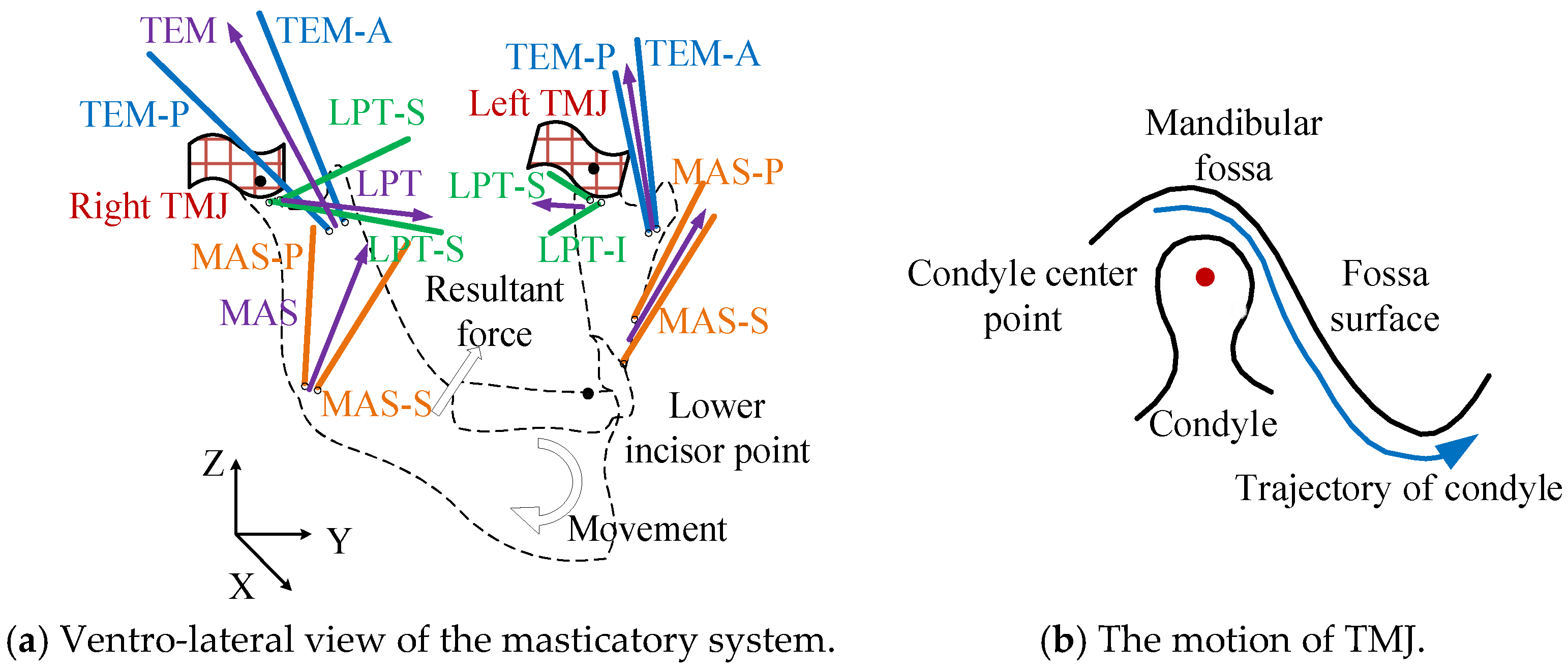
2.1. The Masticatory System

The masticatory system consists of an upper and a lower jaw. The lower jaw is attached to the skull pivoted at the condyle via two TMJs. There are a large number of muscles of various shapes and sizes driving the lower jaw to perform chewing movement, among which the main muscles include masseter, temporalis and lateral pterygoid muscles [7]. Each of them is made up of multiple groups of muscle fibers, i.e., the masseter muscle is composed of MAS-S and MAS-P, as shown in Figure 1a. Different muscle with its line-of-action contributes to masticatory movement in a unique manner. The muscle insertion coordinates and angle of line-of-action of each muscle group are estimated by referring to [14,44]. The resultant force line-of-action of each muscle group (MAS, TEM and LPT) is indicated by the purple arrow in Figure 1a. The TMJ is a joint between the temporal bone and the condyle of the lower jaw. As the joint is treated as a rigid body, the disk and ligament are ignored. The condyle moves anterior and inferior along the mandibular fossa, enabling the mandible to accomplish the translation movement, as shown in Figure 1b. The condyle also revolves on the fossa surface to complete the rotation movement. In general, mastication movement involves both translation and rotation movements at the same time. Different with other joints of human body, like hip or knee joint, these two TMJs are correlative, which are guided by two articular surfaces linked by the rigid lower jaw (see Figure 1).
As there are more muscles driving the lower jaw than required, and two TMJs constraining the motion of the condyle, the human masticatory system itself is mechanically actuation redundant [45]. There is a very short distance in the direction which the condyle moves perpendicular to the articular surface. The articular surface of the TMJ is assumed to be rigid and the condyle keeps contact with the surface all the time. The DOFs of the lower jaw is four.

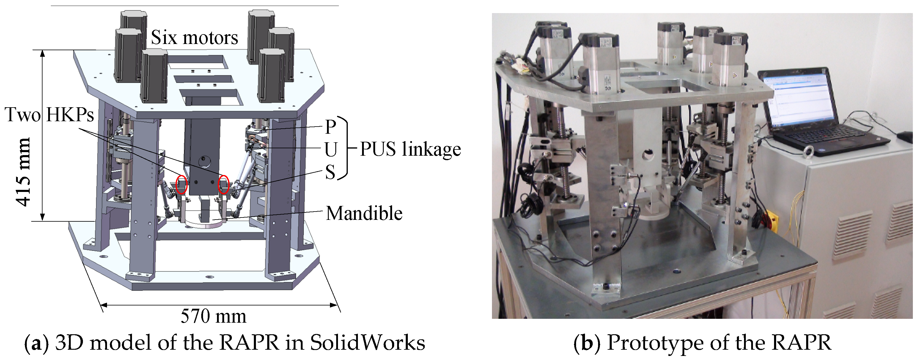
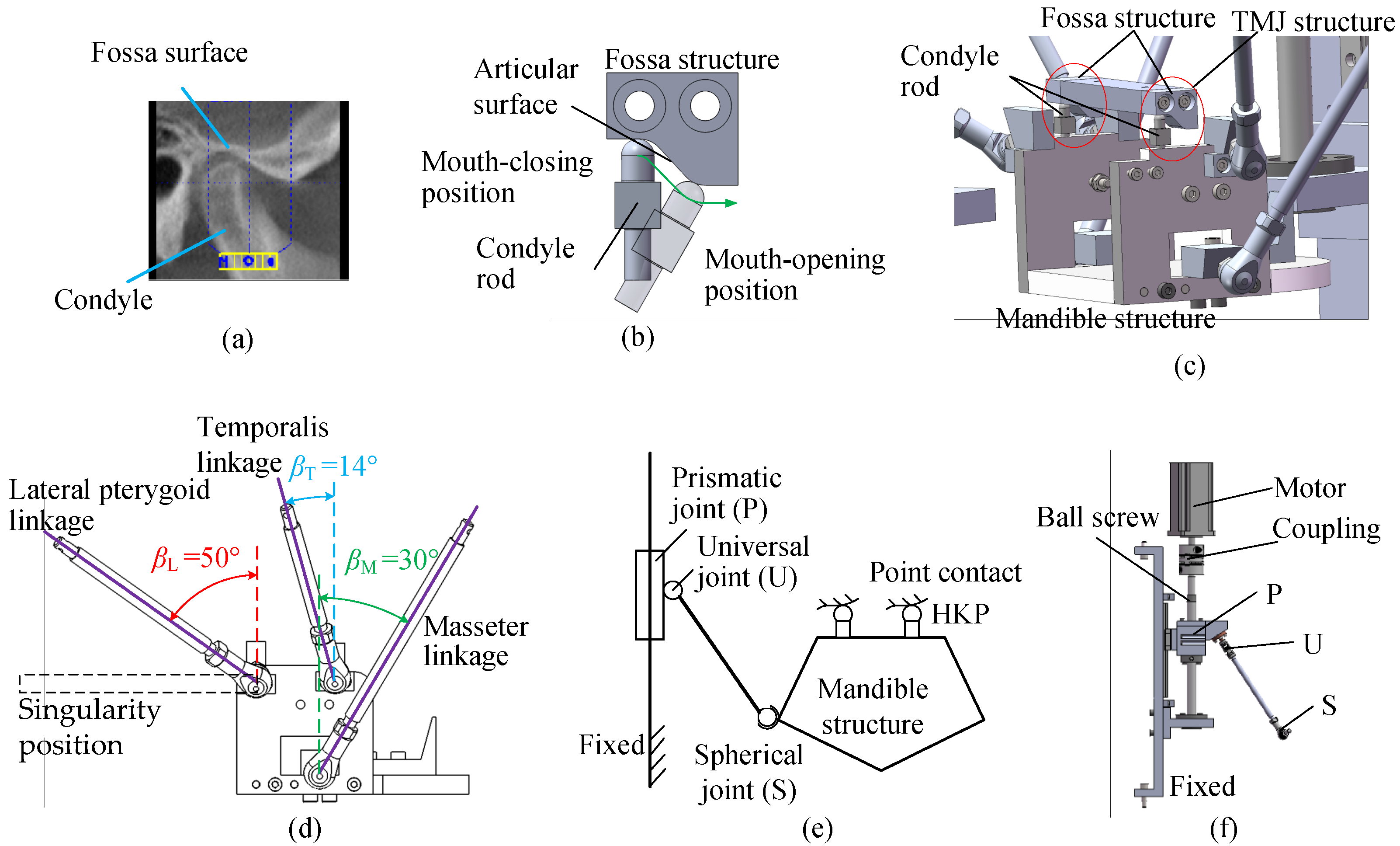
2.2. The Redundantly Actuated Chewing Robot

Inspired by human masticatory system, a 6PUS-2HKP RAPR has been proposed [46]. The major challenge in designing the chewing robot deals with the TMJs and the masticatory muscles. In human TMJ, the two condyles are constrained in moving along the fossa surfaces, as shown in Figure 2a. Although a ball-socket joint has three rotational DOFs, it does not allow for translations. While, the condyle actually moves almost freely along the articular surface of the temporal bone in its articular capsule. Therefore, two point-contact HKPs are designed to model the articular contact of human TMJs. The HKP consists of a condylar rod and a fossa structure, as shown in Figure 2b,c. The condylar rods keep contact with the fossa articular surfaces.
Six PUS chains are arranged in parallel corresponding to the resultant line-of-action of six muscles (MAS, TEM and LPT in Figure 1a) to mimic the main masticatory muscles. The determined angles between each linkage and the vertical plane are shown in Figure 1d. Taking advantage of the bi-directional driving of the engineering solution, six PUS linkage realizes both mouth-closing and mouth-opening functions. To avoid singularity (dotted lines in Figure 2d) when the lateral pterygoid PUS chain is near perpendicular to the sliding rail of the prismatic joint, the tilt angle of lateral pterygoid chain is adjusted to slightly larger than its angle of line-of-action. Figure 2e illustrates the kinematical diagram of the 6PUS-2HKP mechanism with one PUS linkage, as the rest of them are the same. Figure 2f shows the composition of one PUS linkage.
The 3D model of the RAPR and its corresponding prototype are shown in Figure 3. This RAPR is bio-inspired by human evolved masticatory system. In particular, the redundant actuation is achieved by adding passive kinematic constraints, the HKPs. The DOFs of the robot reduce while the number of actuators remain the same. The passive point-contact HKP in the RAPR brings new challenges in stiffness analysis and driving force optimization, but it also helps to reproduce the chewing force more realistically and provide an in vitro experimental platform to study the function of TMJs in human masticatory system.
The left and right articular surface Ls and Rs (indicated in Figure 4) are the surfaces where the centers of the left and right condyles can move along. Each curved surface is made up of two sections, which can be described by two quadratic polynomial curves in XM-ZM plane as follows with respect to frame ΣL0 or ΣMa (see Section 2.3 Figure 4).
z = f ( x ) { z = 0.07 x 2 0.2 x ( 0 x < 8 ) ( x 12.7825 ) 2 + ( z + 2.4568 ) 2 = 36 ( 8 x 13 ) 10 y L 10 , 130 y R 110
where x could be xL or xR and z could be zL or zR. They are coordinates of the center of two TMJs. The subscripts L and R represent the left and right TMJ center, respectively.

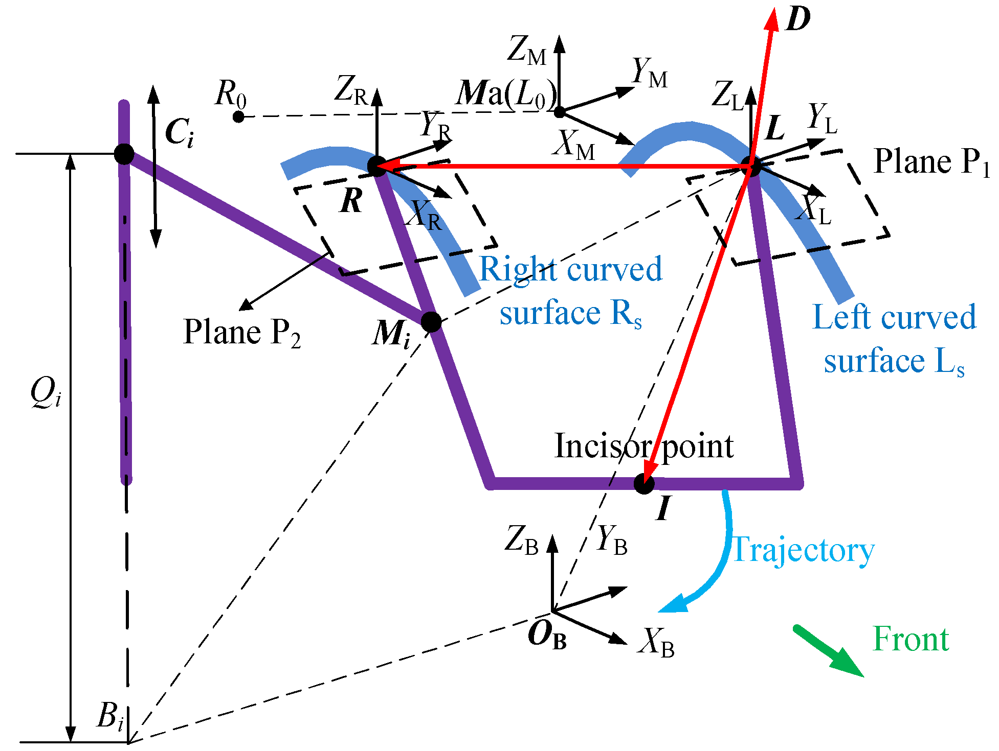
2.3. Reference Frames

Three reference frames are set up in order to describe the motion of the robot, as shown in Figure 4 Bi (i = 1, …, 6) indicates the positions of six prismatic joints on the base. Ci represents the connection point between the prismatic joint and universal joint. Mi represents the center point of the spherical joint. The spherical joints are attached to the mandibular platform. CiMi denotes the six driving rods which link the universal joint and the spherical joint. Mandible frame Ma-XMYMZM (ΣMa) is fixed at the home position of the left TMJ center when the lower and upper teeth are in occlusion. Global reference frame OB-XBYBZB (ΣB) is established on the base just under ΣMa. The left instantaneous frame L-XLYLZL (ΣL), which moves with the mandible, is placed at the center of left TMJ. Frame ΣB is located at ZM = −167 mm, having the same orientation with ΣMa. Point L and R represent the left and right center point of two HKPs, respectively.
The pose of end-effector with respect to the base can be described by three arbitrary non-collinear points. The three points may be selected anywhere on the end-effector. Generally, the platform joints of a PR are in a same plane. While, the redundantly actuated chewing robot is a 3D spatial one and all spherical joints Mi and universal joints Ci of this robot are not in the same plane. The expression of coordinates of platform joints in global frame in terms of three end-effector points will be more complicated than the robot whose platform joints are in same plane.

3. Differential Kinematics

3.1. Inverse Kinematics

The three end-effector points are selected as L, R and I, as shown in Figure 4. The coordinates of platform spherical joints in mandible frame in terms of three end-effector points can be expressed as:
L M i = k 1 , i L R + k 2 , i L I + k 3 , i L D
where L D = L R × L I . Vector LD is perpendicular to both LR and LI. Then, for each i, the three unknowns (k1,i, k2,i and k3,i) in Equation (2) can be obtained in terms of initial position coordinates of points L, R, I and Mi.
In consideration of the HKPs constrains, four generalized variables are able to describe the position and pose of the robot. Assuming G is the generalized variables, four independent parameters xI, yI, zI and xL are chosen to describe the motion of the robot. The rest of three end-effector points’ coordinates yL, zL, xR, yR and zR can be calculated based on the geometric constraints. These nine coordinate parameters of three end-effector points are defined as E.
Left HKP keeps contact with constrained surface, we have:
z L = f ( x L )
where, f indicates the constraint Equation (1). zL can be calculated. The length of LI is constant, then we have:
L I = l LI
From Equation (4), yL can be obtained. Similarly, as RL and RI all have fixed length and right HKP keeps contact with right constrained surface, the following equations can be written:
{ ( x R x L ) 2 + ( y R y L ) 2 + ( z R z L ) 2 = R L 2 ( x R x I ) 2 + ( y R y I ) 2 + ( z R z I ) 2 = R I 2 z R = f ( x R )
where xR, yR and zR can also be obtained by using Equation (5). Then the coordinates of platform joints Mi can be calculated from Equation (2).
Based on the geometric constraints of parallel kinematic chains, the joint variables Qi(i=1, 2, …, 6) of the 6 PUS kinematic chains can be obtained [46].

3.2. Velocity Analysis and Jacobian Matrix

Jacobian matrix is the generalized transmission ratio of the velocity or force transmission from the input of the joint variables to the output of the generalized variables [47]. This RAPR has mixed translational and rotational DOFs. For this type of RAPR, this section presents a dimensionally homogeneous non-square Jacobian matrix formulation method based on three end-effector points.
For the robot studied in this paper, the length of leg CiMi is constant and leads to:
C i M i 2 = L i 2
Differentiating (6) yields:
V M i C i M i = V C i C i M i
where V M i is the velocity of spherical joint, and V C i the velocity of prismatic joint, indicated by Q ˙ i .
The position of Mi in global frame can be expressed as:
O B M i = O B L + k 1 , i L R + k 2 , i L I + k 3 , i L D
Differentiating (8) gives:
V M i = M ˙ i = ( 1 k 1 , i k 2 , i ) L ˙ + k 1 , i R ˙ + k 2 , i I ˙ + k 3 , i [ R ˙ × ( I L ) + L ˙ × ( R I ) + I ˙ × ( L R ) ]
where I (short for O B I ) is coordinate of point I in global frame, andL and R are the abbreviations in the same way. L ˙ = [ x ˙ L ,   y ˙ L ,   z ˙ L ] T , R ˙ = [ x ˙ R ,   y ˙ R ,   z ˙ R ] T and I ˙ = [ x ˙ I ,   y ˙ I ,   z ˙ I ] T .
Combining (7) and (9), yields:
[ A 1 , 1 A 2 , 1 A 3 , 1 A 1 , 2 A 2 , 2 A 3 , 2 A 1 , 6 A 2 , 6 A 3 , 6 ] [ L ˙ R ˙ I ˙ ] = [ e C 1 M 1 0 0 0 e C 2 M 2 0 0 0 e C 6 M 6 ] [ Q ˙ 1 Q ˙ 2 Q ˙ 6 ]
where A 1 , i = [ ( 1 k 1 , i k 2 , i ) C i M i + k 3 , i ( R I ) × C i M i ] T ,
A 2 , i = [ k 1 , i C i M i + k 3 , i ( I L ) × C i M i ] T , and
A 3 , i = [ k 2 , i C i M i + k 3 , i ( L R ) × C i M i ] T , i = 1, 2, …, 6.
If nine velocity variables L ˙ , R ˙ and I ˙ are known, the velocities of prismatic joints Q ˙ i ( Q ˙ 1 , Q ˙ 2 , , Q ˙ 6 ) can be calculated by (10). While, we only know four generalized velocity variables x ˙ I ,   y ˙ I ,   z ˙ I ,   x ˙ L . The five remaining velocity variables can be obtained by velocity projection theory. On a rigid body, projection of velocity vectors of any two points on the line through these two points are the same. For example, regarding velocities of point I and L, we have:
[ x ˙ I ,   y ˙ I ,   z ˙ I ] L I = [ x ˙ L , y ˙ L , z ˙ L ] L I
in which, L I = [ x LI , y LI , z LI ] T .
The instantaneous velocity vector of a condyle point is in a plane that goes through the condyle center and is tangent to the curved surface as shown in Figure 4, Plane P1 and P2.
The slope of P1 in Xm-Zm plane can be calculated by the equation of left curved surface Ls. So does the slope of P2:
m P 1 = f L ( x L )
Since the resultant velocity vector VL must be in the plane P1, the slope m P 1 can also be calculated by:
z ˙ L = m P 1 x ˙ L
Substituting z ˙ L into (11), y ˙ L can be obtained. Similarly, x ˙ R , y ˙ R , z ˙ R can also be obtained. Writing in matrix form, we have:
E ˙ ( 9 × 1 ) = P ( 9 × 4 ) G ˙ ( 4 × 1 )
where P is a matrix that can be obtained by velocity projection theory aforementioned, and E ˙ ( 9 × 1 ) = [ L ˙ , R ˙ , I ˙ ] T .
Equation (10) can be rewritten as:
A ( 6 × 9 ) E ˙ ( 9 × 1 ) = B ( 6 × 6 ) Q ˙ ( 6 × 1 )
Combining (14) and (15), gives:
Q ˙ ( 6 × 1 ) = B ( 6 × 6 ) 1 A ( 6 × 9 ) P ( 9 × 4 ) G ˙ ( 4 × 1 )
The inverse Jacobian matrix of the RAPR can be written as:
J RA 1 = B 1 A P
JRA−1 is a 6 × 4 matrix.

4. Stiffness Analysis and Optimization of Driving Force

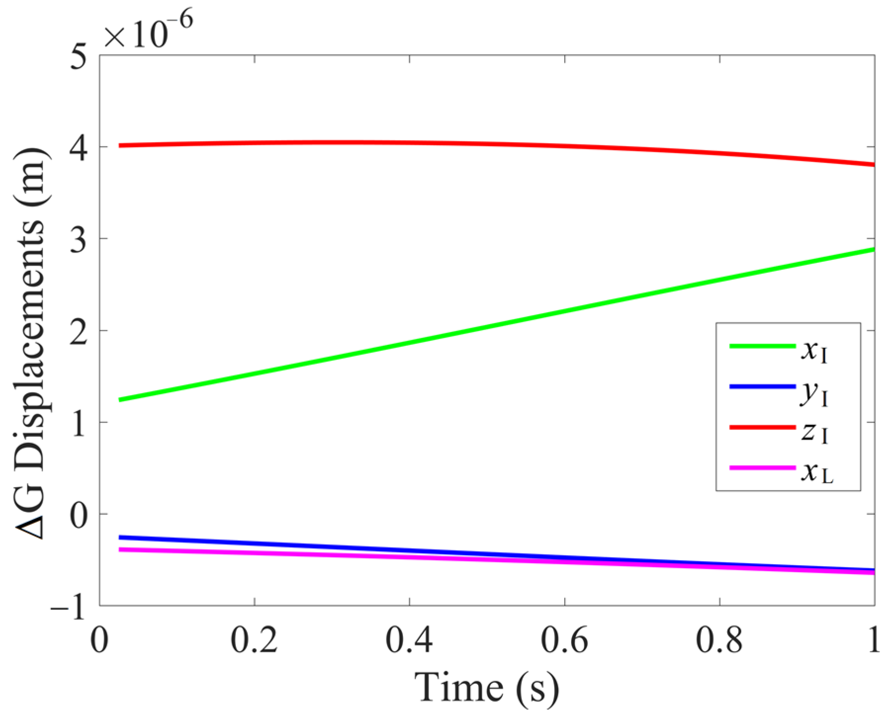
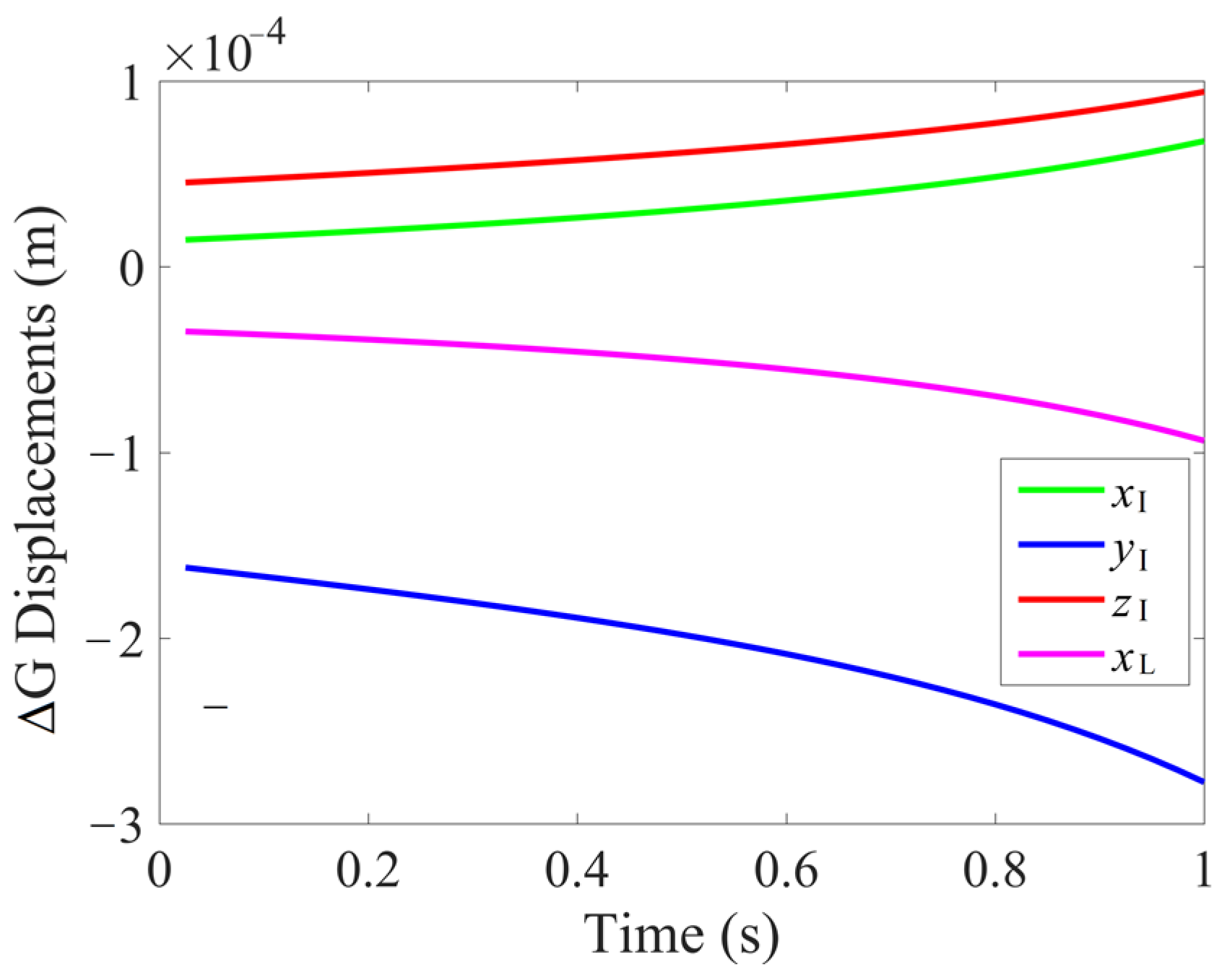
4.1. Stiffness Analysis

Stiffness is a very important performance index in parallel robots [48]. Redundant actuation has been proved to be an effective way to improve its stiffness [26]. The redundant actuation of this 6PUS-2HKP RAPR is achieved by adding two passive point-contact constraints HKPs to the 6-PUS parallel mechanism. In order to investigate the effect of point-contact HKP constraint on the redundantly actuated chewing robot, the stiffness analysis of redundantly actuated 6PUS-2HKP and non-redundantly actuated 6-PUS mechanism are compared.
The relation between Cartesian generalized velocity and joint velocity can be obtained by combining Equations (16) and (17):
Q ˙ = J RA 1 G ˙
The infinitesimal displacements in the Cartesian space and joint space can be written as:
Δ Q = J RA 1 Δ G
Based on virtual work principle, the relation between external force F and prismatic joint force τ can be written as:
τ T Δ Q = F G T Δ G
The joint force τ can also be computed by:
τ = K C Δ Q
where KC is a diagonal matrix which consists of stiffness of the driving system.
Combining Equations (19)–(21), the following equation can be obtained.
F G = J RA T K C Δ Q = J RA T K C J RA 1 Δ G
Therefore, the stiffness matrix of the RAPR can be defined as:
K = J RA T Κ C J RA 1
The generalized infinitesimal displacements of the end-effector can be expressed by:
Δ G = K 1 F G
In this derivation, the basic assumptions in this paper are: (1) The end-effector and the base are assumed as rigid bodies, as the rigidities of them are much larger than that of the six driving rods; (2) the weights of the legs are neglected; (3) the joints are assumed rigid and frictionless; (4) the stiffness of the motors and coupler is equal and is assumed as rigid. All of the six motors actuate the six prismatic joints through ball screw and they have the same rigidity. In one PUS linkage, only the ball screw and the driving legs are taken into account. As the prismatic joints are the direct actuated joints, the model can be simplified as follows. The stiffness matrix of one linkage is approximately calculated by the following equation:
K C i 1 = K bs i 1 + K dr i 1
where KC is the scalar stiffness parameter. Kbs and Kdr stand for the stiffness parameters of the ball screw and driving rod, respectively. Kbs and Kdr can be computed as:
K j = E j A j / L j
where E is the Young’s modulus of the material, A the sectional area of the link, L the length of the link, and j = bs, dr. The scalar stiffness parameters of six linkages can computed as follows. KC1 = KC2 = 2.11 × 10⁷ N/m, KC3 = KC4 = 1.88 × 10⁷ N/m, KC5 = KC6 = 2.57 × 10⁷ N/m.
In the numerical simulation, a mouth-opening trajectory was implemented to estimate the deformation displacement occurring to 6PUS-2HKP RAPR and 6-PUS PR. The motion of the RAPR in terms of the incisor point (point I) with respect to frame ΣB is shown in Figure 5. The motion lasted 1 s and a resultant force (80 N in ZB-direction and 20 N in XB-direction) was continuously applied to point I. During this process, the deformation displacements Δ G at different configuration of the robot were calculated, as shown in Figure 6. The largest deformation displacement is 4.047 × 10⁻⁶ m in ZI direction and the smallest one is 2.573 × 10⁻⁷ m in -YI direction. It can be seen that the RAPR at each configuration has small infinitesimal displacements, which means that it owns a high stiffness.
To highlight the role of redundant actuation in improving the stiffness, the deformation displacement of the non-redundantly actuated 6-PUS PR was also computed. The displacement of the 6-PUS PR under the same mouth-opening trajectory is shown in Figure 7. Having the same geometric parameters with the 6PUS-2HKP RAPR, the smallest deformation displacement of the non-redundantly actuated 6-PUS PR is 1.451 × 10⁻⁵ in XI direction, which is larger than any deformation displacements of the RAPR at each configuration. By comparison of these two robots, one can see that the redundantly actuated 6PUS-2HKP RAPR experiences smaller deformation displacements under the same force. It can be concluded from the numerical simulation that the 6PUS-2HKP RAPR with two HKPs mimicking human TMJs owns better stiffness than the non-redundantly actuated 6-PUS PR counterpart.

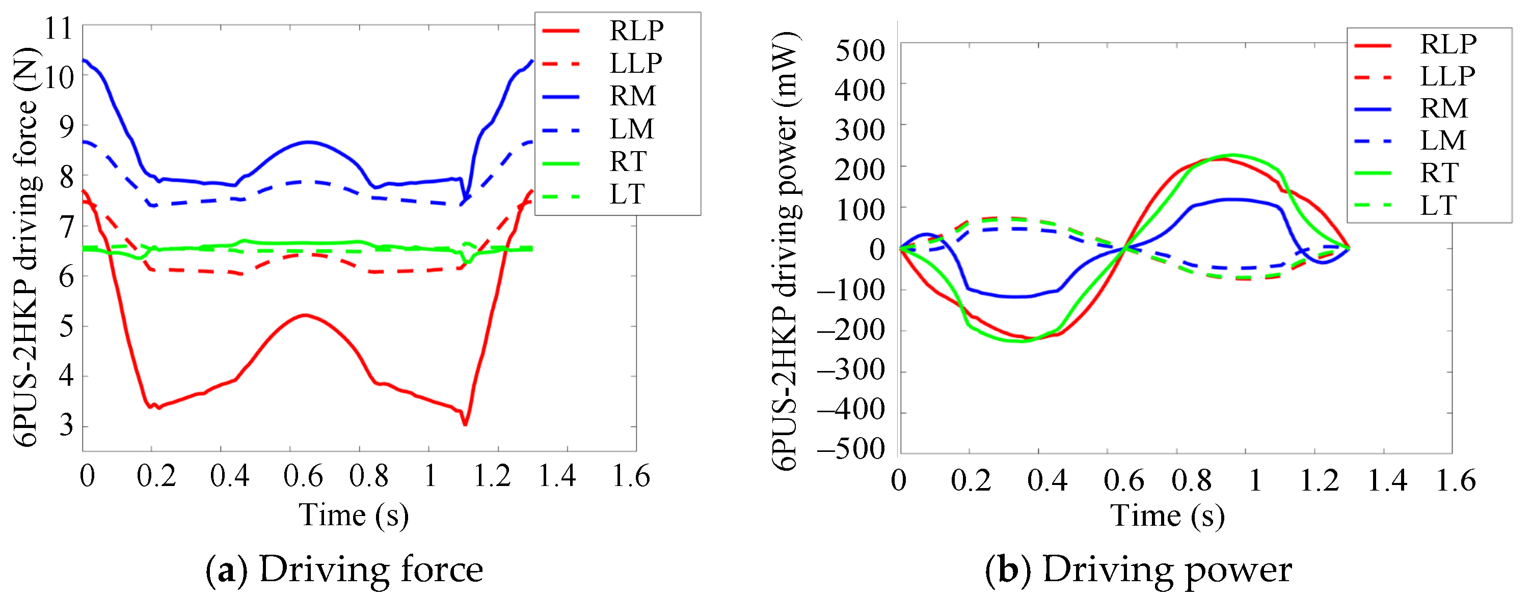
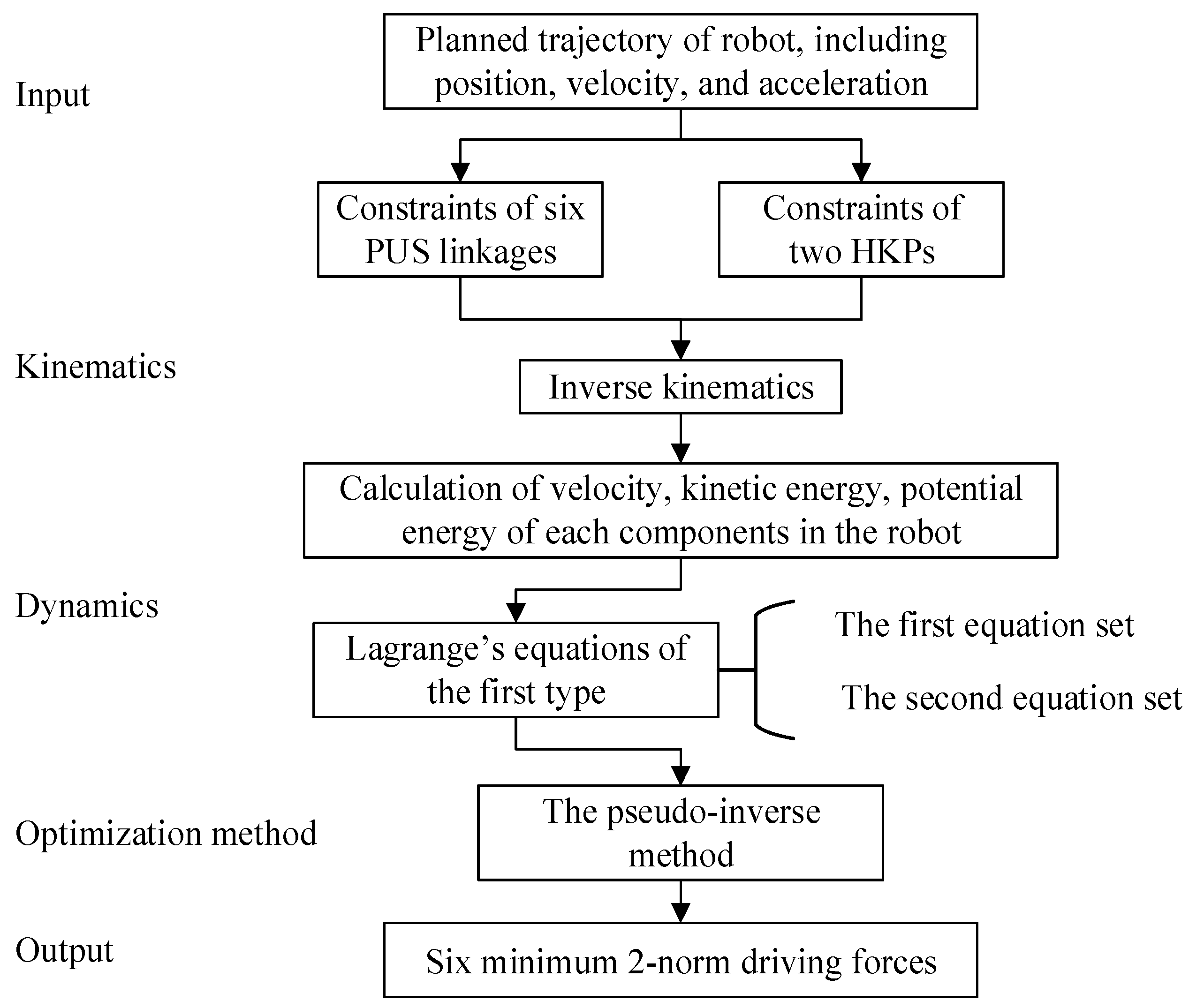
4.2. Optimization of Driving Force

The inclusion of HKP into 6-PUS mechanism brings new features to the chewing robot. On the one hand, redundant actuation of the RAPR causes the inverse dynamics of robot lacks a unique solution. On the other hand, it also allows redistribution of driving force by dynamics. This section will investigate the effect of point-contact HKP constraint in this redundant actuation system from the perspective of dynamics. The driving forces of the RAPR are optimized by finding the minimum Euclidean norm solution. The optimization flow chart is shown in Figure 8. The inverse kinematics has been discussed in Section 3.1. From this foundation, the velocity, kinetic energy, potential energy of the six PUS linkages and end-effector can be calculated, the details of which are not provided due to the limited space.
Lagrange’s equations are used to derive the dynamics of the RAPR. The Lagrange’s equations of the first type can be written in two sets. The first equation set can be written as:
i = 1 6 λ i Γ i q j = d d t ( L q ˙ j ) L q j Q g j ( j = 1 , , k )
where L is the Lagrange function; Qgj represents the generalized force on the end-effector and k is the number of generalized coordinates, k = 4; i indicates the number of constraint equations, i = 6; n is the sum of i and k, n = 10; Γi is the ith constraint equation; qj indicates the four generalized position parameters XL, YL, βL and γL in Cartesian space. βL and γL are the Euler angles. Let GC be [xL, yL, βL, γL]T. As the robot has four DOFs, the generalized forces Q g j = [ F gx , F gy , M g β , M g γ ] T are defined as forces in XL and YL direction and torques around YL and ZL. Considering the geometric constraints of each kinematic chain, link CiMi has a fixed length Li and leads to:
Γ i = C i M i 2 L i 2 = 0 ( i = 1 , 2 , , 6 )
The second equation set, relating the driving torque/force (driving force of slider in this paper), can be expressed by:
τ i = Q a j = d d t ( L q ˙ j ) L q j i = 1 k λ i Γ i q j ( j = k + 1 , , n )
where τi (Qaj) is the driving force.
According to the optimization algorithm of pseudo-inverse method, the minimum 2-norm solution τ0 can be obtained:
τ 0 = [ Γ G C ( Γ Q ) 1 ] 6 × 4 RM [ Γ G C ( Γ Q ) 1 ] 4 × 6 [ d d t ( L Q ˙ ) L Q ] 6 × 1 [ Γ G C ( Γ Q ) 1 ] 6 × 4 RM [ d d t ( L G ˙ C ) - L G C F g ] 4 × 1
where [ Γ G C ( Γ Q ) 1 ] 6 × 4 RM is the right pseudo-inverse matrix of [ Γ G C ( Γ Q ) 1 ] 4 × 6 . τ0 denotes the six minimum 2-norm driving forces.
The trajectory of left lateral movement was analyzed in this simulation, shown in Figure 9. The position, velocity, and acceleration of the six prismatic joints for the given pose of mandible can be determined by inverse kinematics.
Following the same lateral movement, the driving force and driving power of 6PUS-2HKP RAPR and its counterpart non-redundantly actuated 6-PUS parallel robot were solved by dynamics equations for comparison. The driving force and power of 6-PUS robot without optimization algorithm are illustrated in Figure 10 and Table 1. The driving forces from the most significant to the least significant in sequence are masseter, lateral pterygoid, and temporalis. The maximum force is that of LM which is 10.78 N and the minimum force is that of RT which is 6.27 N. As the velocity of RLP is the largest, the RLP has a maximum power of 0.487 W.
The driving forces of the 6PUS-2HKP RAPR adopting pseudo-inverse optimization method are shown in Figure 11 and Table 1. Compared with the 6-PUS robot, the driving forces of the six prismatic joints reduces dramatically, especially the lateral pterygoid and the masseter. The maximum force is that of RM which is 10.26 N and the minimum force occurs at the RLP which has a value of 3.36 N. As we can see from the standard deviation of the power in Table 1, the driving power also becomes more balanced and the power consumption has improved. The RT has a maximum power 0.224 W. None of any kinematic chain of 6PUS-2HKP RAPR has a very sharp power curve compared with the 6-PUS robot.
The highlight of the role of the point-contact HKP constraints in the 6PUS-2HKP RAPR is homogenizing driving force and driving power. The driving force decreases and the driving power becomes more homogenous by applying the pseudo-inverse optimization method.

5. Chewing Experiment

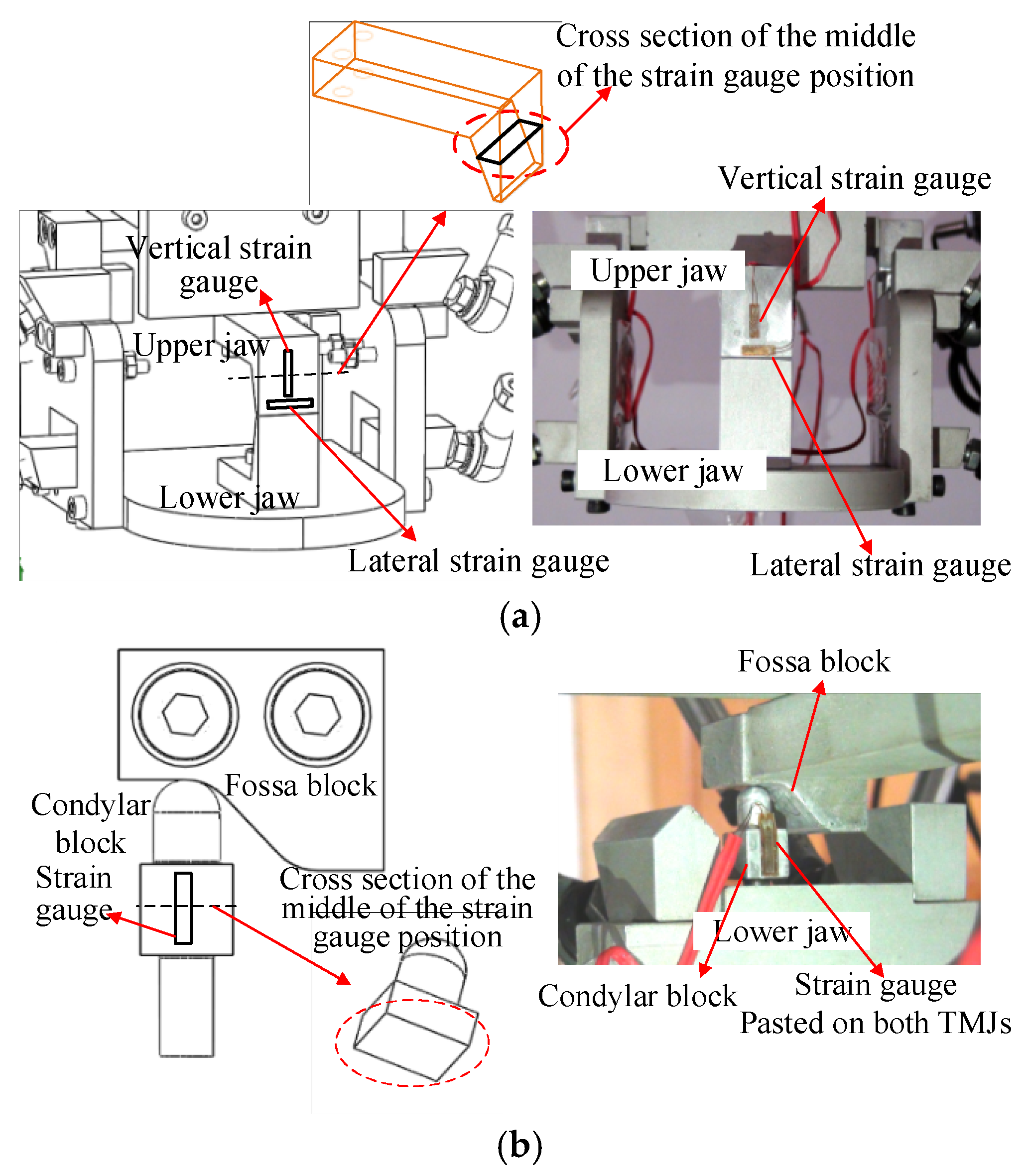
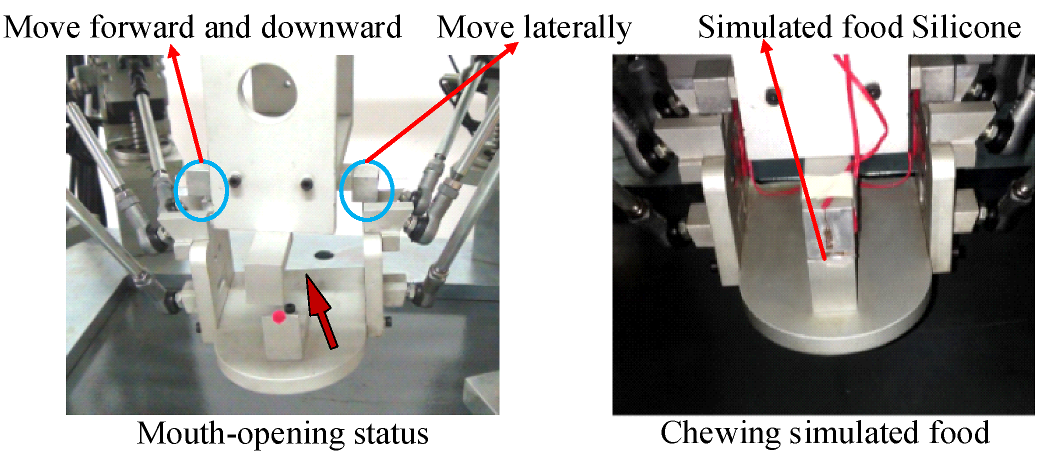
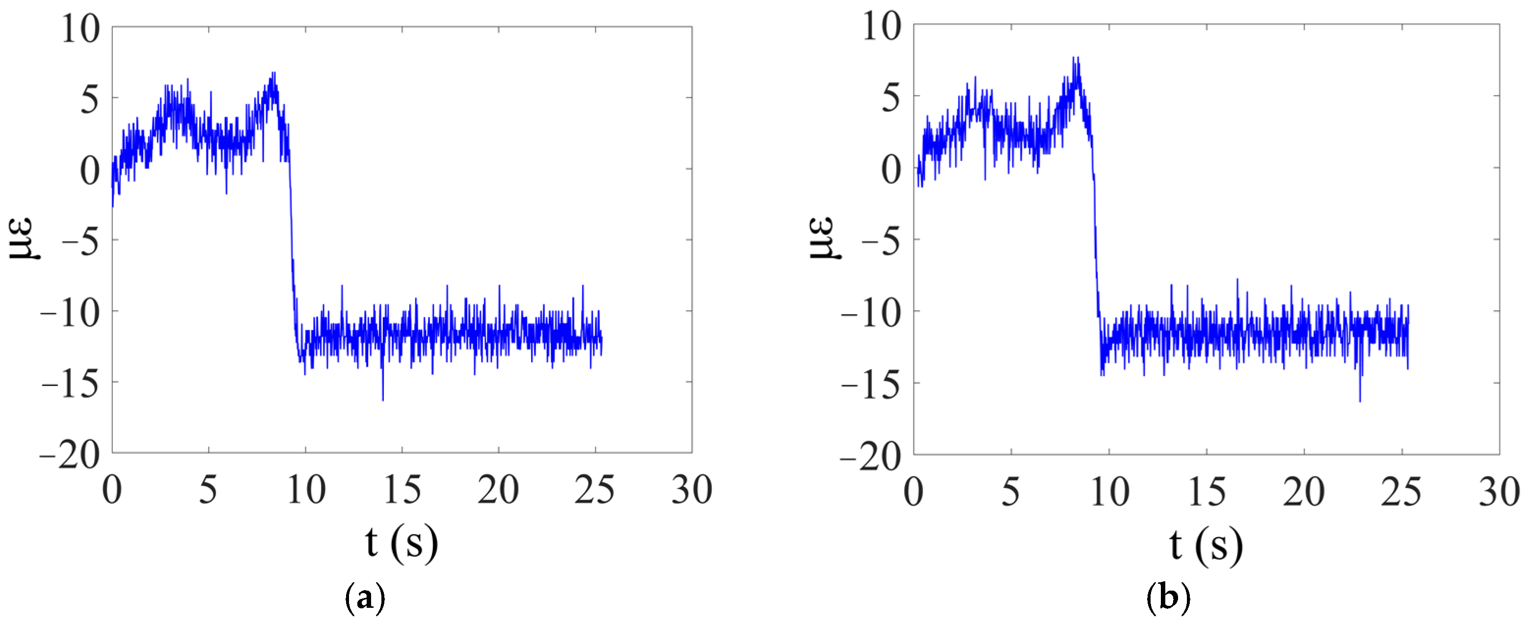
5.1. Measurement Methods for Chewing Simulated Food

In this paper, the reaction forces on the occlusal surface of incisor and on the mandibular condyle are regarded as the occlusal forces and the TMJ (HKP) forces, respectively. For the purpose of studying the relation between occlusal force and TMJ force of the chewing robot, a real-time force measurement system was built. Due to the size of the point-contact HKP constraints, the strain gauge is selected as the force sensor. Two strain gauges are glued perpendicular to each other on the upper jaw, as shown in Figure 12a. The vertical one is used for measuring the occlusal force and the lateral one is for lateral force on teeth. The other two strain gauges are glued on left condylar rod and right condylar rod, respectively, as shown in Figure 12b. These two strain gauges sense the HKP force in real time.
As the chewing robot was intended to perform a variety of trajectories between lateral and vertical chewing, the trajectories may vary. A desired chewing trajectory was profiled according to characteristics of human chewing trajectory. The given trajectories of the mandible are determined by the four independent position parameters. The motion controller computes the kinematics in a time interval of 2 ms to get the parameters of the six servo motors. The chewing trajectory of the chewing robot is shown in Figure 13 with respect to frame ΣB.
Simulated food is adopted to conduct chewing test on the chewing robot in order to obtain the occlusal force and TMJ force. Two kinds of materials silicone (SI) and polyethylene (PE) are chosen as the simulated food, as shown in Figure 14. As different thicknesses of simulated food can produce different value of force, silicone with 4 mm, 8 mm and 12 mm thick and polyethylene with 1 mm, 2 mm thick are adopted during the chewing cycle in this paper.
In the experiment, the forces in one chewing cycle was recorded on the chewing robot prototype. At the opening phase, the simulated food was put between the upper jaw and the lower jaw (incisor position). When the mouth closed to the occlusal phase, the simulated food was chewed by the robot. Figure 15 shows a silicone simulated food is being chewed by the chewing robot. Different simulated food was tested one by one.

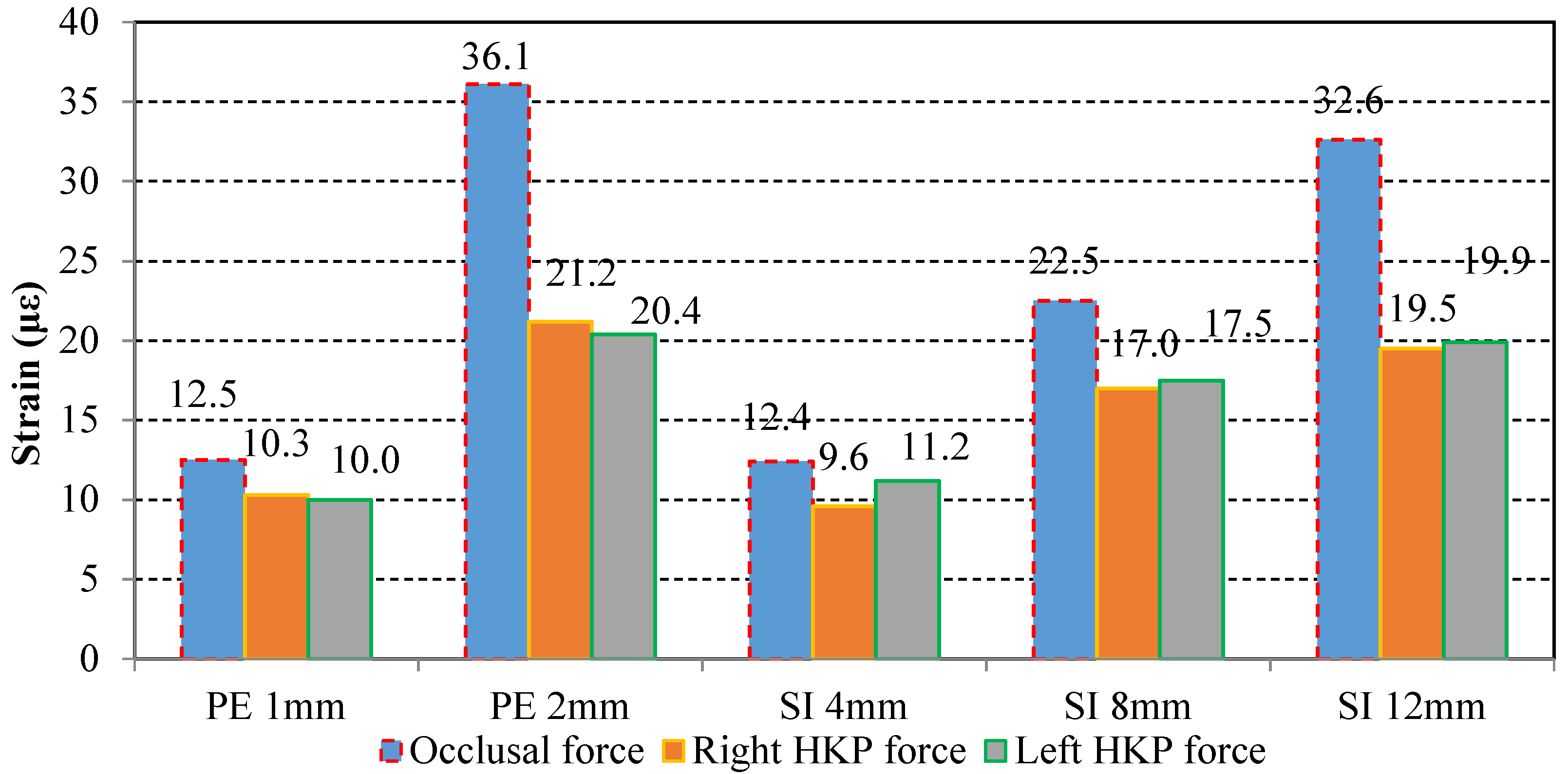
5.2. Experimental Results of Occlusal Force and TMJ Force

Once the chewing robot started chewing the simulated food, both the upper jaw structure and the condyle rod were stressed. The occlusal force and TMJ force expressed by strains were collected by the strain data acquisition system during the chewing course. The strains of the four sensors with 1 mm thick polyethylene in one chewing cycle are shown in Figure 16 and Figure 17.
The force can be calculated with the following methods. The material of the TMJs and upper jaw is aluminum alloy and the modulus of elasticity of them is 0.7 × 10⁵ MPa. Based on the definitions of stress and strain and Hooke’s Law, the stress can be obtained:
σ = E ε = 0.7 × 10 11 × 12.5 × 10 6 = 8.75 × 10 5
where σ is the stress of the upper jaw. E is the Young’s modulus of aluminum alloy and ε is the strain shown in Figure 16b. The occlusal force can be calculated as follows:
F = σ A = 8.75 × 10 5 × 1.2 × 10 4 = 105
where F is the occlusal force and A is the cross-sectional area of the middle position of strain gauge on upper jaw (Figure 12a). Similarly, the cross-sectional area of the condylar block is 49 × 10−6 m2 and the TMJ force can also be calculated. Multi-group experiments were carried out and the occlusal forces and TMJ forces were also calculated.
The results are shown in Figure 18 and Figure 19. As can be seen from the bar chart, the occlusal force increases with thicknesses of two kinds of simulated food increases directly. The increase of the occlusal force causes the TMJ forces become larger. The results verify that the loading of the TMJ increases along with occlusal force.
The maximum occlusal force occurred when the robot chews the 2-mm thick polyethylene, which is 303.2 N and the corresponding left and right TMJ force is 70.0 N and 72.7 N, respectively. The minimum occlusal force is 104.2 N and corresponding left and right TMJ force is 32.9 N and 38.4 N when the robot bites the 4-mm thick silicone. The occlusal force increases by 190.98% from silicone with 4 mm thick to polyethylene with 2 mm thick. Nevertheless, the corresponding left TMJ force only increases by 120.97% and the right TMJ force only increases by 82.29%. It can be seen from the changing process of the two forces that the growth rate of occlusal force is larger than that of TMJ force.
The maximum bite force that human can apply to the molars which has been measured about 700 N or higher in healthy people [49,50], approximately equal to human’s own weight. While the size of the condyle is only about 20 × 10 × 10 mm [33], which is too small to burden such a large loading compared with the knee joint of human body. From the perspective of theory of mechanism, redundant actuation allows to partially control the internal forces and the actuating force and power consumption of actuators can be redistributed by optimization methods.
Redundant actuation in masticatory system may help us to reveal the physiological phenomenon. In this experiment, it shows the increment of occlusal force has priority over the TMJ force. It means the two point-contact HKPs in the redundant actuated system have a positive effect on generating process of chewing force caused by actuators. This suggests the forces of these two TMJs play a role in optimizing the internal force of the redundant actuated system, enabling the muscle group to output more efficient occlusal force during chewing process.
Besides, the average value of occlusal force on incisor of a healthy young adult is about 146.17 N [51]. As we can see the force that the chewing robot can produce in this experiment is much larger than the average force. The robot is able to output enough occlusal force which can be potentially used in new dental materials test or food properties test. The internal TMJ forces during chewing provides the possibility to study the performance test of TMJ prosthesis.

6. Conclusions

The physical redundantly actuated chewing robot was specified in terms of six PUS linkage and two HKPs. The introduction of HKP allows the chewing robot to be able to reproduce the TMJ movement and influence of the TMJ force on occlusal force. Accordingly, it can improve the bio-imitability of the chewing robot. Unlike the traditional ways of achieving redundant actuation, this RAPR was realized through the inclusion of additional constraints to reduce DOFs, resulting in the number of actuators is larger than the number of DOFs.
In order to investigate the advantage of musculoskeletal actuation redundancy in human masticatory system, such as optimal stiffness, energy efficiency and chewing forces needed for the food breakdown, this paper studies the stiffness and optimization of driving force and presents the chewing experiment of the RAPR. In stiffness analysis, the three end-effector points method was proposed for use in differential kinematics of the RAPR with mixed DOFs, mapping the reduced number of the end-effector’s generalized variables to the joint variables. Based on the dimensionally homogeneous Jacobian matrix, the stiffness simulation results confirmed the 6PUS-2HKP RAPR with two point-contact HKPs has better stiffness than the non-redundantly actuated counterpart 6-PUS PR. In optimization of driving force, Lagrange’s equations were used to derive the dynamics of the RAPR. The driving force of the RAPR was optimized by finding the minimum Euclidean norm solution. By comparison, one can get the same result that the 6PUS-2HKP RAPR with two HKPs performs better than the 6-PUS PR. These simulation results of chewing robot show the musculoskeletal structure of human masticatory system itself has the advantage of good stiffness and energy saving. They also reveal the significance of TMJs in the redundantly actuated human masticatory system.
As the TMJs are modeled as two point-contact HKPs in the proposed robot, the occlusal force generated has more realistic implication. The experiments of chewing simulated food with different thicknesses are carried out to evaluate the occlusal force and the TMJ force. The occlusal force increases with the thicknesses of simulated food, and the corresponding TMJ force also increases, but at a slower rate. From a biomechanical point of view, the experiment also illustrates that the existence of TMJ in human redundantly actuated masticatory system ensures more efficient transmission and transformation from muscle force to occlusal force.
Ongoing research on the robot prototype involves a wear-resistant test of the alloy ceramic crown, which evaluates the wear condition of the occlusal surfaces of the crowns. Future work may focus on developing a new generation of chewing robot. As in the current version, rigid linkages and rigid contacts are used to mimic the muscles and TMJs, respectively, the chewing force and TMJ force generated by the chewing robot are still not completely coincident with human masticatory system. Emphasis in future studies will involve adopting parallel flexible drive system considering the muscle elasticity, and designing soft TMJ structure considering the disc and ligament in the chewing robot.

Author Contributions

Conceptualization, H.W. and M.C.; funding acquisition, H.W. and M.C.; investigation, Y.Z.; methodology, H.W.; project administration, M.C.; software, H.W. and G.W.; supervision, M.C. and Z.Z.; validation, H.W., Z.Z. and Y.Z.; visualization, G.W.; writing—original draft, H.W.; writing—review and editing, M.C. and Z.Z. All authors have read and agreed to the published version of the manuscript.

Funding

This research was funded by National Natural Science Foundation of China, Grant numbers 51705063 and 51575078, and the Natural Science Foundation of Jiangsu Province, China, Grant No. BK20190368.

Institutional Review Board Statement

Not applicable.

Informed Consent Statement

Not applicable.

Data Availability Statement

Not applicable.

Conflicts of Interest

The authors declare no conflict of interest.

References

  1. Flores, E.; Fels, S.; Vatikiotis-Bateson, E. Chew on this: Design of a 6DOF anthropomorphic robotic jaw. In Proceedings of the 16th IEEE International Symposium on Robot and Human Interactive Communication, Jeju, Korea, 26–29 August 2007; pp. 648–653. [Google Scholar]
  2. Alemzadeh, K.; Jones, S.B.; Davies, M.; West, N. Development of a Chewing Robot with Built-in Humanoid Jaws to Simulate Mastication to Quantify Robotic Agents Release from Chewing Gums Compared to Human Participants. IEEE. Trans. Biomed. Eng. 2020, 68, 492–504. [Google Scholar] [CrossRef]
  3. Takanobu, H.; Maruyama, T.; Takanishi, A.; Ohtsuki, K. Mouth opening and closing training with 6-DOF parallel robot. In Proceedings of the 2000 ICRA. Millennium Conference. IEEE International Conference on Robotics and Automation, San Francisco, CA, USA, 24–28 April 2000; pp. 1384–1389. [Google Scholar]
  4. Celebi, N.; Rohner, E.C.; Gateno, J.; Noble, P.C.; Ismaily, S.K.; Xia, J.J. Development of a Mandibular Motion Simulator for Total Joint Replacement. J. Oral Maxil. Surg. 2011, 69, 66–79. [Google Scholar] [CrossRef] [PubMed] [Green Version]
  5. Wen, H.Y.; Cong MWang, G.F.; Qin, W.L.; Xu, W.L.; Zhang, Z.S. Dynamics and Optimized Torque Distribution Based Force/position Hybrid Control of a 4-DOF Redundantly Actuated Parallel Robot with Two Point-contact Constraints. Intern. J. Control Automat. Syst. 2019, 17, 1293–1303. [Google Scholar] [CrossRef]
  6. Naser, M.; Jaspreet, D.; Alexander, V.; John, B.; Xu, W.L. Optimizing the torque distribution of a redundantly actuated parallel robot to study the temporomandibular reaction forces during food chewing. J. Mech. Robot 2020, 12, 1–28. [Google Scholar]
  7. Kandasamy, S.; Greene, C.; Rinchuse, D.; Stockstill, J. TMD and Orthodontics; Springer: Cham, Switzerland, 2015. [Google Scholar]
  8. Kishi, T.; Hashimoto, K.; Takanishi, A. Human Like Face and Head Mechanism. In Humanoid Robotics: A Reference; Goswami, A., Vadakkepat, P., Eds.; Springer: Dordrecht, The Netherlands, 2017. [Google Scholar]
  9. Cid, F.; Moreno, J.; Bustos, P.; Núñez, P. Muecas: A multi-sensor robotic head for affective human robot interaction and imitation. Sensors 2014, 14, 7711–7737. [Google Scholar] [CrossRef] [Green Version]
  10. Ding, H.; Esfahani, M.I.M.; Shen, Y.; Tan, H.; Zhang, C. Hybrid Humanoid Robotic Head Mechanism: Design, Modeling, and Experiments with Object Tracking. In Proceedings of the 2020 8th IEEE RAS/EMBS International Conference for Biomedical Robotics and Biomechatronics (BioRob), New York, NY, USA, 29 November–1 December 2020. [Google Scholar]
  11. Takanobu, H.; Takanishi, A.; Ozawa, D.; Ohtsuki, K. Integrated dental robot system for mouth opening and closing training. In Proceedings of the 2002 IEEE International Conference on Robotics and Automation, Washington, DC, USA, 11–15 May 2002; pp. 1428–1433. [Google Scholar]
  12. Xu, W.L.; Lewis, D.; Bronlund, J.E.; Morgenstern, M.P. Mechanism, design and motion control of a linkage chewing device for food evaluation. Mech. Mach. Theory 2008, 43, 376–389. [Google Scholar] [CrossRef]
  13. Xu, W.L.; Torrance, J.D.; Chen, B.Q.; Potgieter, J.; Bronlund, J.E. Kinematics and experiments of a life-sized masticatory robot for characterizing food texture. IEEE Trans. Ind. Electron. 2008, 55, 2121–2132. [Google Scholar] [CrossRef]
  14. Xu, W.L.; Pap, J.S.; Bronlund, J.E. Design of a biologically inspired parallel robot for foods chewing. IEEE Trans. Ind. Electron. 2008, 55, 832–841. [Google Scholar] [CrossRef]
  15. Raabe, D.; Harrison, A.; Ireland, A.; Alemzadeh, K.; Sandy, J.; Dogramadzi, S.; Melhuish, C.; Burgess, S. Improved single- and multi-contact life-time testing of dental restorative materials using key characteristics of the human masticatory system and a force/position-controlled robotic dental wear simulator. Bioinspir. Biomim. 2012, 7, 016002. [Google Scholar] [CrossRef]
  16. Papo, M.J.; Catledge, S.A.; Vohra, Y.K. Mechanical wear behavior of nanocrystalline and multilayer diamond coatings on temporomandibular joint implants. J. Mater. Sci. Mater. Med. 2004, 15, 773–777. [Google Scholar] [CrossRef]
  17. Mueller, A. Redundant Actuation of Parallel Manipulators. Parallel Manipulators, towards New Applications; I-Tech Education and Publishing: Vienna, Austria, 2008. [Google Scholar]
  18. Shang, W.; Cong, S. Dexterity and Adaptive Control of Planar Parallel Manipulators with and without Redundant Actuation. J. Comput. Nonlinear Dyn. 2015, 10, 011002. [Google Scholar] [CrossRef]
  19. Ebrahimi, I.; Carretero, J.A.; Boudreau, R. 3-PRRR redundant planar parallel manipulator: Inverse displacement, workspace and singularity analyses. Mech. Mach. Theory 2007, 42, 1007–1016. [Google Scholar] [CrossRef]
  20. Lee, G.; Park, S.; Lee, D.; Park, F.C.; Jeong, J.I. Minimizing Energy Consumption of Parallel Mechanisms via Redundant Actuation. IEEE/ASME Trans. Mechatron. 2015, 20, 2805–2812. [Google Scholar] [CrossRef]
  21. Hufnagel, T.; Mueller, A. A projection method for the elimination of contradicting decentralized control forces in redundantly actuated PKM. IEEE Trans. Robot. 2012, 28, 723–728. [Google Scholar] [CrossRef]
  22. Shang, W.; Cong, S.; Ge, Y. Coordination motion control in the task space for parallel manipulators with actuation redundancy. IEEE Trans. Autom. Sci. Eng. 2013, 10, 665–673. [Google Scholar] [CrossRef]
  23. Liu, G.F.; Cheng, H.; Xiong, Z.H.; Wu, X.Z. Distribution of singularity and optimal control of redundant parallel manipulators. In Proceedings of the 2001 IEEE/RSJ International Conference on Intelligent Robots and Systems, Maui, HI, USA, 29 October–3 November 2001; pp. 177–182. [Google Scholar]
  24. Zhu, Z.; Dou, R. Optimum design of 2-DOF parallel manipulators with actuation redundancy. Mechatronics 2009, 19, 761–766. [Google Scholar] [CrossRef]
  25. Marquet, F.; Krut, S.; Company, O.; Pierrot, F. ARCHI: A redundant mechanism for machining with unlimited rotation capacities. In Proceedings of the 2001 IEEE International Conference on Robotics and Automation, Seoul, Korea, 21–26 May 2001; pp. 683–689. [Google Scholar]
  26. Wu, J.; Wang, J.; Wang, L.; Li, T.; You, Z. Study on the stiffness of a 5-DOF hybrid machine tool with actuation redundancy. Mech. Mach. Theory 2009, 44, 289–305. [Google Scholar] [CrossRef]
  27. Wang, L.; Wu, J.; Wang, J.; You, Z. An experimental study of a redundantly actuated parallel manipulator for a 5-DOF hybrid machine tool. IEEE ASME Trans. Mechatron. 2009, 14, 72–81. [Google Scholar] [CrossRef]
  28. Kim, J.; Park, F.C.; Sun, J.R.; Kim, J. Design and analysis of a redundantly actuated parallel mechanism for rapid machining. IEEE Trans. Robot. Autom. 2001, 17, 423–434. [Google Scholar] [CrossRef] [Green Version]
  29. Zhao, Y.; Gao, F. Dynamic performance comparison of the 8PSS redundant parallel manipulator and its non-redundant counterpart-the 6PSS parallel manipulator. Mech. Mach. Theory 2009, 44, 991–1008. [Google Scholar] [CrossRef]
  30. Xu, M.; Rong, C.; He, L. Design and Modeling of a Bio-Inspired Flexible Joint Actuator. Actuators 2021, 10, 95. [Google Scholar] [CrossRef]
  31. Wang, W.; Hou, Z.G.; Cheng, L.; Tong, L.; Peng, L.; Peng, L.; Tan, M. Toward patients’ motion intention recognition: Dynamics modeling and identification of iLeg—An LLRR under motion constraints. IEEE Trans. Syst. Man Cybern. Syst. 2017, 46, 980–992. [Google Scholar] [CrossRef]
  32. Kim, J.; Yang, J.; Yang, S.T.; Oh, Y.; Lee, G. Energy-Efficient Hip Joint Offsets in Humanoid Robot via Taguchi Method and Bio-inspired Analysis. Appl. Sci. 2020, 10, 7287. [Google Scholar] [CrossRef]
  33. Takanobu, H.; Takanishi, A.; Kato, I. Design of a mastication robot using a human skull model. In Proceedings of the 1993 IEEE/RSJ International Conference on Intelligent Robots and Systems (IROS’93), Yokohama, Japan, 26–30 July 1993; pp. 203–208. [Google Scholar]
  34. Vilimek, M.; Goldmann, T. Computation of forces acting in temporomandibular joint and masticatory muscles during mastication. Comput. Method. Biomech. Biomed. Eng. 2011, 14, 267–268. [Google Scholar] [CrossRef]
  35. Tanaka, E.; Koolstra, J.H. Biomechanics of the temporomandibular joint. J. Dent. Res. 2008, 87, 989–992. [Google Scholar] [CrossRef] [PubMed]
  36. Mercuri, L.G. Temporomandibular Joint Total Joint Replacement- TMJ TJR; Springer International Publishing: Cham, Switzerland, 2016. [Google Scholar]
  37. Iwasaki, L.R.; Baird, B.W.; McCall, W.D., Jr.; Nickel, J.C. Muscle and temporomandibular joint forces associated with chincup loading predicted by numerical modeling. Am. J. Orthod. Dentofacial Orthop. 2003, 124, 530–540. [Google Scholar] [CrossRef]
  38. Nickel, J.C.; Iwasaki, L.R.; Walker, R.D.; Mclachlan, K.R.; McCall, W.D., Jr. Human masticatory muscle forces during static biting. J. Dent. Res. 2003, 82, 212–217. [Google Scholar] [CrossRef]
  39. Koolstra, J.H. Dynamics of the human masticatory system. Crit. Rev. Oral Biol. Med. 2002, 13, 366–376. [Google Scholar] [CrossRef] [PubMed] [Green Version]
  40. Koolstra, J.H.; Eijden, T.M.G.J.V. Prediction of volumetric strain in the human temporomandibular joint cartilage during jaw movement. J. Anat. 2006, 209, 369–380. [Google Scholar] [CrossRef] [PubMed]
  41. Park, J.T.; Lee, J.G.; Won, S.Y.; Lee, S.H.; Cha, J.Y.; Kim, H.J. Realization of masticatory movement by 3-dimensional simulation of the temporomandibular joint and the masticatory muscles. J. Craniofacial Surg. 2013, 24, 347–351. [Google Scholar] [CrossRef]
  42. Iwasaki, L.R.; Petsche, P.E.; McCall, W.D., Jr.; Marx, D.; Nickel, J.C. Neuromuscular objectives of the human masticatory apparatus during static biting. Arch. Oral Biol. 2003, 48, 767–777. [Google Scholar] [CrossRef]
  43. May, B.; Saha, S.; Saltzman, M. A three-dimensional mathematical model of temporomandibular joint loading. Clin. Biomech. 2001, 16, 489–495. [Google Scholar] [CrossRef]
  44. Koolstra, J.H.; Eijden, T.M.G.J.V. Dynamics of the human masticatory muscles during a jaw open-close movement. J. Biomech. 1997, 30, 883–889. [Google Scholar] [CrossRef]
  45. Koolstra, J.H.; Eijden, T.M.G.J.V. A method to predict muscle control in the kinematically and mechanically indeterminate human masticatory system. J. Biomech. 2001, 34, 1179–1188. [Google Scholar] [CrossRef]
  46. Wen, H.; Xu, P.; Cong, M. Kinematic Model and Analysis of an Actuation Redundant Parallel Robot With Higher Kinematic Pairs for Jaw Movement. IEEE Trans. Ind. Electron. 2014, 62, 1590–1598. [Google Scholar] [CrossRef]
  47. Merlet, J.P. Jacobian, manipulability, condition number and accuracy of parallel robots. J. Mech. Des. 2005, 128, 199–206. [Google Scholar] [CrossRef]
  48. Pulloquinga, J.L.; Escarabajal, R.J.; Ferrándiz, J.; Vallés, M.; Mata, V.; Urízar, M. Vision-Based Hybrid Controller to Release a 4-DOF Parallel Robot from a Type II Singularity. Sensors 2021, 21, 4080. [Google Scholar] [CrossRef]
  49. Ferrario, V.F.; Sforza, C.; Zanotti, G.; Tartaglia, G.M. Maximal biteforces in healthy young adults are predicted by surface electromyography. J. Dent. 2004, 32, 451–457. [Google Scholar] [CrossRef]
  50. Okiyama, S.; Ikebe, K.; Nokubi, T. Association between masticatory performance and maximal occlusal force in young men. J. Oral Rehabil. 2003, 30, 278–282. [Google Scholar] [CrossRef]
  51. Ferrario, V.F.; Sforza, C.; Serrao, G.; Dellavia, C.; Tartaglia, G.M. Single tooth bite forces in healthy young adults. J. Oral Rehabil. 2004, 31, 18–22. [Google Scholar] [CrossRef]
Figure 1. The composition of the masticatory system and TMJ (MAS-S: superficial masseter, MAS-P: deep masseter, TEM-A: Anterior temporalis, TEM-P: Posterior temporalis, LPT-S: Superior lateral pterygoid, LPT-I: Inferior lateral pterygoid; MAS, TEM and LPT represent the resultant force line-of-action of masseter, temporalis and lateral pterygoid muscles, respectively. Only the main muscles are shown).
Machines 09 00171 g001
Figure 2. Mechanism of the 6PUS-2HKP RAPR: (a) CT scan of the fassa surface; (b) design of the HKP; (c) the layout of the two HKPs; (d) Lateral view of three linkages with symmetrical layout; (e) Kinematical diagram of the RAPR with one PUS linkage (Other linkages are omitted); (f) design of one PUS linkage (P: prismatic joint, U: Universal joint, S: Spherical joint).
Machines 09 00171 g002
Figure 3. Redundantly actuated chewing robot.
Machines 09 00171 g003
Figure 4. Reference frames and schematic diagram of the robot (Other five linkages are omitted in this figure).
Machines 09 00171 g004
Figure 5. Movement of point I with respect to frame ΣB.
Machines 09 00171 g005
Figure 6. Deformation displacement of 6PUS-2HKP RAPR.
Machines 09 00171 g006
Figure 7. Deformation displacement of non-redundantly actuated 6-PUS PR.
Machines 09 00171 g007
Figure 8. The flow chart of the driving force optimization.
Machines 09 00171 g008
Figure 9. Input trajectory parameters of the RAPR.
Machines 09 00171 g009aMachines 09 00171 g009b
Figure 10. Driving force and power of non-redundant 6-PUS parallel mechanism (Right lateral pterygoid-RLP; left lateral pterygoid-LLP; right masseter-RM; left masseter-LM; right temporalis-RT; left temporalis-LT).
Machines 09 00171 g010
Figure 11. Driving force and power of 6PUS-2HKP RAPR.
Machines 09 00171 g011
Figure 12. Position of the strain gauge: (a) Strain gauge on upper jaw, (b) strain gauge on TMJ (HKP).
Machines 09 00171 g012
Figure 13. Chewing trajectory of the chewing robot.
Machines 09 00171 g013
Figure 14. Different simulated food chewed by the chewing robot: (a) Silicone; (b) Polyethylene.
Machines 09 00171 g014
Figure 15. Picture of chewing simulated food.
Machines 09 00171 g015
Figure 16. Strain on the upper jaw: (a) Lateral strain, (b) Vertical strain.
Machines 09 00171 g016
Figure 17. Strain on the condyles of TMJs: (a) Strain of right TMJ, (b) Strain of Left TMJ.
Machines 09 00171 g017
Figure 18. Strain of jaw and HKPs of different simulated food with different thicknesses.
Machines 09 00171 g018
Figure 19. Occlusal force and TMJ (HKP) force of different simulated food with different thicknesses.
Machines 09 00171 g019
Table 1. Comparison of driving force and power between 6-PUS and 6PUS-2HKP mechanism (Fmin, Fmax, Fmean-The minimum, maximum and mean value of the driving force, respectively; Pmax-The maximum value of the power; PSD-The standard deviation of the power).
MechanismParametersRLPLLPRMLMRTLT
6-PUSFmin (N)7.718.259.6010.496.276.48
Fmax (N)8.488.6510.4110.786.716.65
Fmean (N)8.188.5310.0410.616.566.54
Pmax (mW)487.4103.3152.968.2226.370.7
PSD340.370.7100.044.8154.448.3
6PUS-2HKPFmin (N)3.366.047.537.396.256.46
Fmax (N)7.717.4710.268.676.686.63
Fmean (N)4.626.428.457.766.556.53
Pmax (mW)216.373.9117.947.8224.470.6
PSD157.950.877.731.5154.148.2
Publisher’s Note: MDPI stays neutral with regard to jurisdictional claims in published maps and institutional affiliations.

