1. Introduction
With the rapid development of science and technology, robot, as an advanced tool that integrates a number of advanced technologies, are having more and more impacts on human society. For complex and dynamic tasks and environments, a multi-robot system has the advantages of lower operating costs, fewer system requirements, stronger adaptability, and flexible scalability, when compared to a single robot [
1].
Among all kinds of robots, unmanned ground vehicles (UGVs) and unmanned aerial vehicles (UAVs) have been widely used in civilian and military fields. UAVs can provide a global and accurate view of the environment by making use of their fast moving speed and their being less prone to GPS signal interruption. UGVs have high load capacity and can endure long-term task requirements. Air-ground coordination systems, formed by combining the functional characteristics of UAVs and UGVs, can not only effectively avoid weaknesses such as the short flight time of UAVs and poor perception of UGVs, but also provide breakthrough ideas for multi-robot coordination systems with huge heterogeneity and functional complementarity [
2,
3]. Air-ground coordination systems have been widely used in many scenarios, such as agriculture [
4], rescue [
5], exploration [
6], and surveillance [
7].
UAV-UGV coordination systems can be classified into eight different settings, from the perspective of the functional roles that UGVs and UAVs have in a system [
8]. The functional roles of UAVs and UGVs can be divided into: sensors, actuators, decision makers, and auxiliary facilities. UAV-UGV coordination systems can be expressed as <X|Y>, where X is the functional role of UAVs and Y is the functional role of UGVs. Most air-ground coordination systems can be classified as different types using different combinations of UAV and UGV roles [
9,
10,
11,
12]. One typical class is written as <S,D|A>, where UAVs act as sensors and decision makers, and UGVs act as actuators. This class of systems is of particular interest because there are tasks that UGVs cannot complete by their own intelligence. For example, a UGV may fall into a local minimum when avoiding multiple obstacles (e.g., stops in the middle between two obstacles). This necessitates UAV intervention for UGV on-line in the process of task execution. In this case, UAVs perceive the environment from the air and make decisions for UGVs. This type of system traditionally collects information through the manual control of UAVs, which help path planning for UGVs offline [
13]. Such a process has difficulty in coping with dynamic environments. Many researchers propose to achieve path planning and control on-line [
14,
15]. However, this is limited in cases when UGVs do not need UAVs to make perception decisions when performing their basic tasks. In addition, on-line decision making and path planning bring communication and computation burdens. Therefore, key problems arise as how to build a decision-making model for UAV intervention and how to solve the problem of task conflicts between external interventions and the UGVs own tasks.
To solve the potential decision-making/planning/control conflicts, the null space behavior control (NSBC) method is one of the potential solutions, where different basic tasks for UAVs and UGVs are defined as behaviors with assigned priority. This method ensures that, under the premise of the complete execution of high-priority tasks, the partial execution of secondary tasks is possible [
16]. An air-ground cooperative formation method based on the NSBC has been proposed to ensure that the formation shape can be maintained when UGVs or UAVs encountered obstacles [
17,
18,
19]. A new type of human decision-making behavior model has been proposed in the framework of the NSBC using an event-triggered mechanism [
20]. The human intervention task, with the highest priority, is triggered only when defined decision variables reach a threshold. It reduces the burden of communication and computation by intervening robots in an event-triggered way and enables human assistance to complete tasks beyond robots’ own capabilities. However, the existing methods cannot avoid risks brought on by bad or malignant interventions from either humans or UAVs.
Motivated by the above discussions, in this paper, we focus on how UAVs intervene with UGVs to improve the overall intelligence of the system, while reducing the burden of communication and computation. The contributions of this paper can be summarized as follows. First, a new type of air-ground coordination system is proposed, which can be written as <S,D,A|S,D,A>, where both UAVs and UGVs have the ability to perceive, make decisions, and execute tasks. It extends the unidirectional intervention that existing works consider to bidirectional interventions. Second, the drift diffusion model (DDM) and model predictive control (MPC) are introduced into the NSBC framework to accurately determine the timing of intervention, to achieve an optimal trade-off between decision speed and accuracy, and to predict whether an intervention is correct and acceptable. The latter decision-making acceptance problem is formulated into an integer programming problem and solved using current state and future predictions.
The rest of this paper is organized as follows. In
Section 2, we briefly introduce preliminaries of the NSBC; In
Section 3, the UAV and UGV task design and decision making model based on event-triggered way is presented; In
Section 4, the intervention task decision maker based on MPC is presented; In
Section 5, simulation cases are studied and discussed;
Section 6 concludes the paper.
2. Preliminary
Let’s briefly review the NSBC methods [
21], by defining as
mathematical expressions for the behavior to be achieved (usually called tasks).
is defined as a variable vector describing the system configuration. In general, they are related through the following models:
with the corresponding differential relationship:
where
is the configuration-dependent task Jacobian matrix and
is the system velocity. The reference velocity
is to act at the differential level by inverting the (locally linear) mapping and pursueminimum-norm velocity, leading to the least-squares solution:
where
is the reference trajectory,
is the pseudo-inverse of the Jacobian matrix. Since the discrete-time integration of the reference velocity will cause the numerical drift of the reconstructed position, the following closed loop inverse kinematics (CLIK) form is used to compensate for the drift:
where
is the derivative of the desired task function.
is a suitable constant positive definite matrix of gains.
is the task error.
Consider there are N tasks, and each task is assigned a priority (expressed by subscript
i,
i = 1 means the highest priority ). The NSB solution to the task combination can be formulated in an iterative way, defining the velocity vector as follows:
where
,
, and the matrix
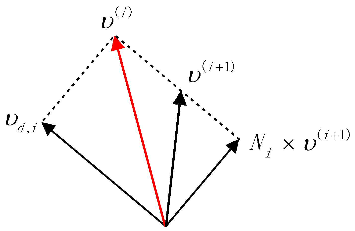
is the null space projector matrix of Jacobian. In sum, corresponding to a lower priority task, are projected onto the null space of the immediately higher priority task; then, eventually, conflicting velocity components are cut off, before being added to higher priority task velocity components. The geometric model of its comprehensive velocity output is shown in
Figure 1.
3. Framework Design of Air-Ground Coordination Systems
This paper proposes an air-ground coordination system framework for UAVs to intervene UGVs through an event-triggered mechanism. As shown in
Figure 2, The DDM is employed for simple decision-making modeling by accumulating decision variables. Bayes’ risk criterion is used to achieve the optimal trade-off between decision speed and accuracy, which is in charge of setting the decision threshold. The combination of the two achieves an accurate judgment on the timing of intervention [
22]. When the decision variable does not reach the threshold, intervention is triggered, hence reducing the communication resources needed. To solve task conflicts, DDM is embedded into the NSBC framework for UAVs to determine whether and when to intervene in UGVs. When the decision variable has not reached the threshold, the UAVs and UGVs perform their own basic tasks. When the decision variable reaches the decision threshold, UGVs can no longer rely on their own intelligence, and the UAVs need to intervene to help make decisions.
3.1. Task Planning Layer Task Design
3.1.1. UGV Basic Task Function Design
UGV Move-to-Target Task Function Design
The movement of the UGV to the target point is defined as the task of moving to the target point. Once the target point is reached, the task is completed and the UGV stops moving. Define the location of the target point
, location of UAV.
as a controllable task variable
. Define the position to reach the target point as the desired function
. Then, the output of the UGV motion task is:
where
B is defined as the UGV motion task gain.
is the Jacobian pseudo-inverse matrix for the motion task.
is the task errors.
UGV Obstacles-Avoidance Task Function Design
The UGV needs to avoid obstacles detected by the sensor when moving along the reference trajectory to the target point. In order to ensure the safety of the UGV during its movement, obstacle avoidance tasks can provide basic guarantees. Define the location of UGV is
. Obstacle location is
. The obstacle avoidance task function is:
Define the desired function of obstacle avoidance task as
, which d is the obstacle avoidance safety distance. Then, the output of the obstacle avoidance task function is:
where
A is defined as the UGV obstacles-avoidance task gain.
is the Jacobian pseudo-inverse matrix for the obstacles-avoidance task.
is the obstacles-avoidance task errors.
3.1.2. UAV Basic Task Function Design
UAV Obstacles-Avoidance Task Function Design
Although the working environment of the UGV is relatively simple for the ground environment, it is necessary to design the task of avoiding obstacles.The task design process is the same as the obstacle avoidance task design of the UGV. Therefore, the output of the UAV obstacle avoidance task is
where
A is defined as the UAV obstacles-avoidance task gain.
is the Jacobian pseudo-inverse matrix for the UAV obstacles-avoidance task.
is the UAV desired obstacle-avoidance task function, and
is the UAV obstacles-avoidance task function.
is the UAV obstacles-avoidance task errors.
3.1.3. Composite Task Function Design
Composite task refers to the combination of multiple basic tasks according to task priority. Define
as the
task function,
, where
is the dimension of the task space. Moreover, we further define the task hierarchy which follows the rules [
23]:
- (1)
Assume that b = r is the lowest priority, and b = 1 is the top priority. Here, > implies that is the index of a lower priority than ; a task of priority may not disturb another task of priority . The lower-priority tasks are executed in the null space of all higher priority tasks.
- (2)
The mappings from the velocities to the task velocities are captured by the task Jacobian matrix , .
- (3)
The dimension of the lowest level task may be greater than so that n is ensured to be greater than the total dimension of all tasks.
Following the aforementioned rules, the composite task velocity of UAV or UGV can be obtained by Equation (5).
3.2. UAV Intervention Task Design
In this paper, only the supervision behavior and intervention behavior of UAV to UGV are considered. The supervision behavior is defined by UAV monitoring the UGV task execution process without intervention, until failure is detected. The intervention behavior is defined by UAV intervening UGV. For the UAV supervision behavior, there is no task input to the UGV. Instead, for the UAV intervention behavior, task input to the UGV should be provided. Thus, the task corresponding to the UAV intervention behavior should be designed.The intervention task will be set as the highest priority task execution of the UGV, and the original task of the UGV will be projected onto the null space of the intervention task of the UAV. Define the desired UAV intervention task function as:
where
is the is the real-time position of the UGV that the UAV would intervene. The derivative of the UAV intervention task is given by
where
is the intervention Jacobian matrix. Therefore, the output of the UAV intervention task is
where
is defined as the UAV intervention task gain.
is the Jacobian pseudo-inverse matrix for the UAV intervention task.
is the UAV intervention task function.
is the UAV intervention task error.
Assumption 1. UAVs can give intervention tasks .
Remark 1. Intervention tasks can be given by fuzzy logic [24], reinforcement learning [25], neural network [26] method. 3.3. Decision-Making Layer Design
The decision-making layer consists of DDM and Bayes Risk criteria. The DDM is a cognitive process modeling method in the “two-choice forced decision-making problem”, which is suitable for simple decision-making process modeling. This model accumulates decision information under external noise. When the accumulated decision information reaches any decision threshold, the choice corresponding to the decision threshold is selected as the final decision result. In this paper, DDM is used as the event-triggered way for UAV intervene in UGV, embedded in the NSBC framework. The formula for the DDM of UAV is as follows.
The decision variables should be selected to reflect the progress of the robot to complete the task. In this paper, the task error of the UGV of the NSBC method is selected as the decision variable of the UAV. The task error is , where is the preset trajectory and is the trajectory planned by NSBC. is the drift rate, which characterizes the amount of change of the decision variable per unit time. is white noise conforming to Gaussian distribution, which represents the influence of noise during the accumulation process of decision information.
The generation of UAV decision threshold requires the introduction of Bayes’ risk criterion function. This function can minimize the decision risk and realize the trade-off between decision speed and accuracy. The Bayes’ risk criterion function is the weighted sum of decision time (
T) and decision deviation (
E). The formula is as follows:
where
and
are the correlation coefficients of decision time and decision deviation, respectively. The formulae for decision time
T and decision deviation
E are as follows.
where
is the decision deviation at the initial moment. Since the decision deviation
E decreases exponentially with the increase of the threshold
, and the decision time
T increases with the increase of
, the Bayes’ risk criterion function has a minimum value. By minimizing this function and solving for
, the decision threshold
is obtained.
At this time, when the decision variable has not reached the decision threshold, the UGV maintains its original task output. When the decision variable reaches the decision threshold, it indicates that the UGV is currently unable to complete the task with its own intelligence, and the UAV needs to give an intervention task to intervene the UGV to get out of the predicament. The original task of the UGV is projected onto the null space of the intervention task of the UAV, ensuring that once the intervention task is given, it will be executed as the highest priority task, and the original task of the UGV will be partially executed. At this time, the output formula of the UGV task is as follows:
5. Simulation
In this part, consider an UAV and two UGVs moving in the x-y-z three dimensional space, where each robot is modeled as a first-order system. The goal of the entire air-ground coordination system is to move to the target point and avoid obstacles in an unknown environment. The UAV is equipped with cameras to sense UGVs ground environment; UGVs are equipped with sensors to sense surrounding obstacles. The values of parameters used in this simulation are shown in
Table 1.
First, this paper proposes three verification methods for the air-ground collaborative system framework. (a) The UGV encountered a local minima point, and the UAV did not take intervention measures. (b) The UGV encounters a local minima point, and the UAV takes effective intervention to prompt the UGV to get rid of the extreme point. (c) The UGV encounters a local minima point, the UAV gives a bad intervention, and the UGV chooses not to accept the intervention task.
Next, two case studies are given to better demonstrate the advantages of the proposed UAV-UGV coordination system’s event-triggered intervention framework.
5.1. Case A
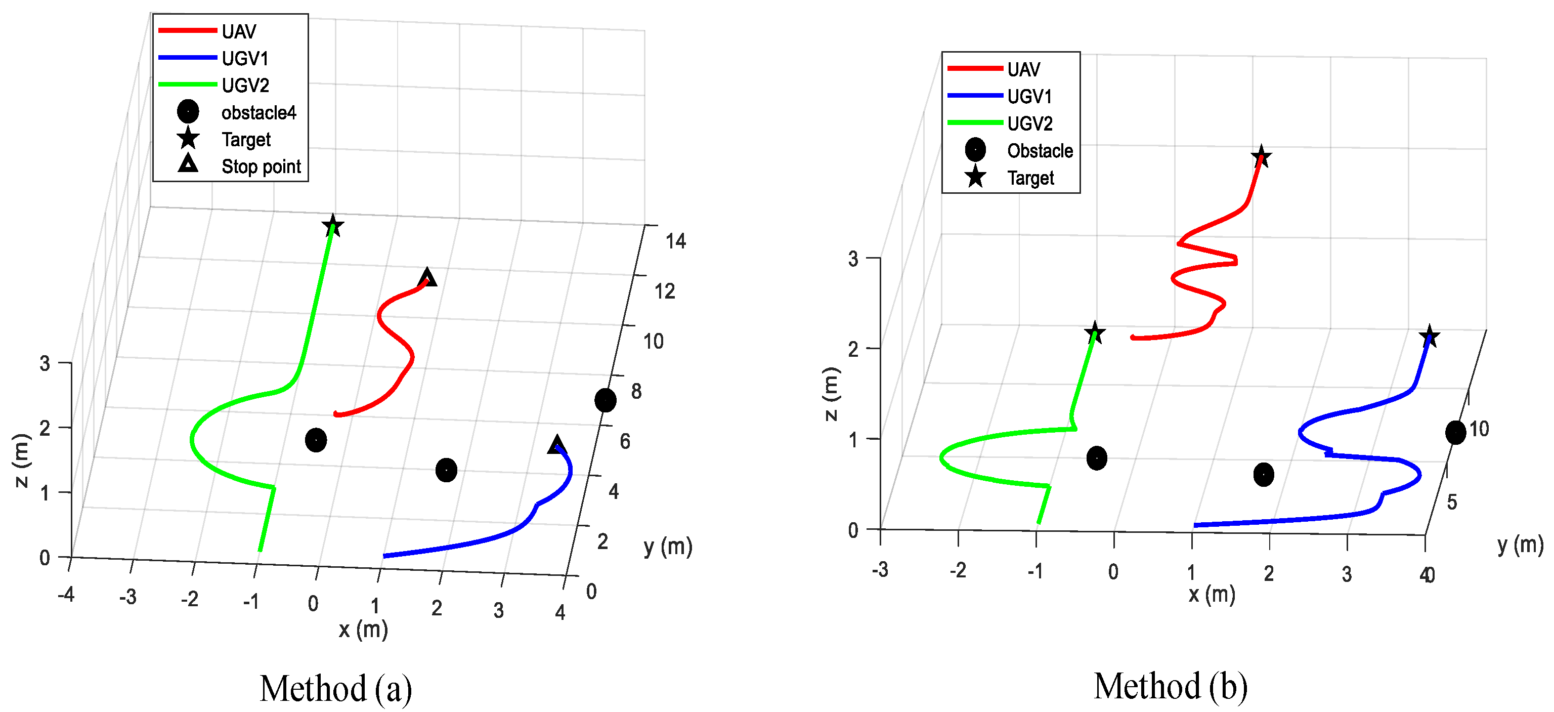
In this case, the effective intervention of UAV is verified by comparing method (a) and method (b). In the process of UGV performing tasks, there may be situations in which they cannot rely on their own intelligence to solve problems. For example, when a UGV faces two obstacles and performs an obstacle avoidance task, the sum of the speed vectors of the two obstacle avoidance tasks will have the same magnitude as the speed vector moving to the target point, but the direction will be opposite, which makes it stuck in the local minima point. Trajectory diagram of the air-ground system with no intervention measures taken by UAV and effective intervention measures taken by UAV shown in
Figure 3.
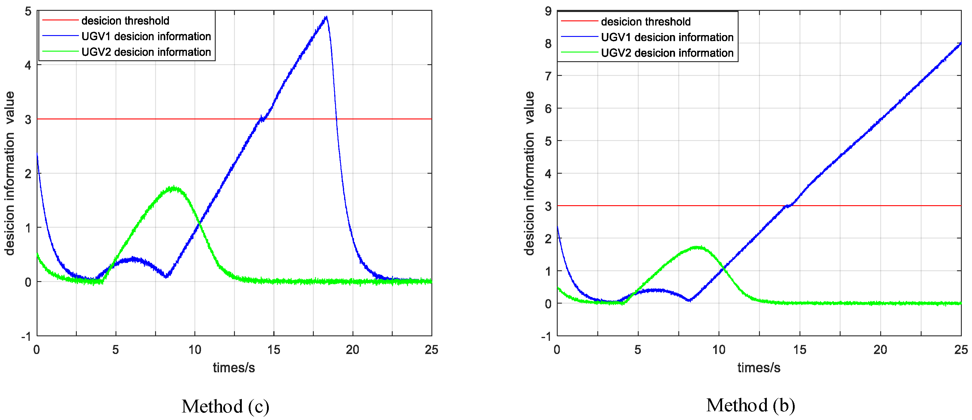
In method (a), the UGV2 can complete the task by virtue of its own intelligence. Since the UAV did not effectively intervene in the UGV1, the UGV1 fell into a minimum value at (3.3 m, 5.1 m). The UAV’s decision variable for UGV1 keeps increasing until it exceeds the decision threshold, but the intervention task is not triggered. Through the effective intervention of UAV in method (b) at time 14.45 s, after the decision variable of UGV1 exceeds the threshold, it will fall back below the threshold after 1.7 s. It shows that, after the effective intervention of the UAV, the UGV1 has been able to complete the task with its own intelligence. The decision variables of the UAV are shown in
Figure 4.
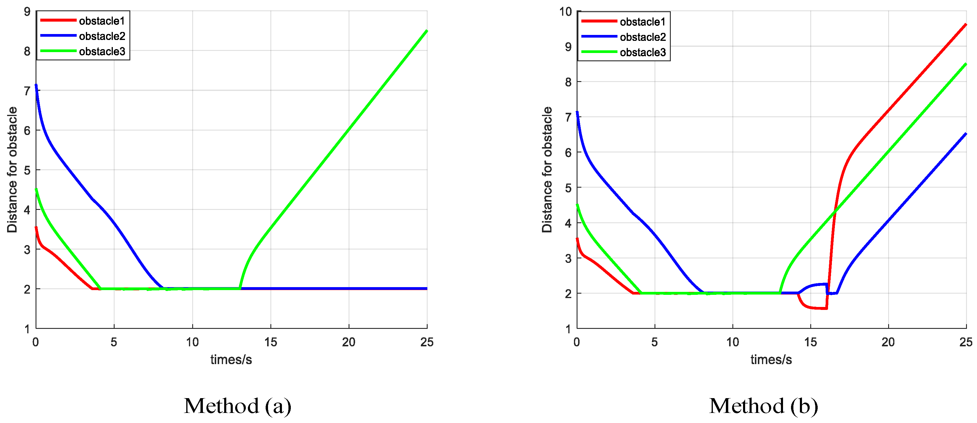
Figure 5 shows the distances between the UGVs and their nearby obstacles. Once the UGV is moving into the range of the obstacle or another UGV, the obstacle avoidance task is activated with a higher priority to avoid collision. Method (a) shows that the UGV1 is stuck in the extreme point and cannot move, and the distance from the obstacle is constant at 2 m. Method (b) shows that the UGV1 can get rid of the extreme point by effective intervention.
Figure 6 shows that in method (b), only when the decision variable reaches the decision threshold, will the UAV launch an intervention task. After the MPC intervention task decision maker, the UGV chooses to accept the intervention task. Method (a): Since it does not involve event triggering, it is not shown here.
5.2. Case B
In this case, by comparing method (b) and method (c), it is verified whether the UGV accepts the undesirable intervention task given by the UAV, so as to ensure its own safety. In method (b), due to factors such as disturbance or visual occlusion, the UAV gives the wrong intervention task, which causes UGV to collide with the sudden obstacle and cause danger. In method (c), since the MPC intervention task decider optimizes the intervention task and the UGV’s original composite task, when the wrong intervention task is given, the UGV chooses not to accept the intervention task. Until an effective intervention task is given, the UGV chooses to perform the intervention task. Please note that, at this time, due to the formation task of the UAV, the UAV’s trajectory is also shifted. The trajectory of method (c) and method (b) are shown in
Figure 7.
In method (b), the wrong intervention task causes the UGV to crash into sudden obstacles (5.5 m, 5.8 m), which causes the UAV to continuously increase the decision variables of the UGV1 due to the failure of the UGV1. In method (c), although the UAV’s decision variables will continue to increase due to the maintenance of its original task until UAV effectively intervenes task to make the UGV get rid of the extreme point, at least the safety of the UGV is protected. As shown in
Figure 8.
It can be seen from
Figure 9 that the wrong intervention task of method (b) causes the distance between the UGV and the sudden obstacle to be zero. Method (c) effectively avoids this situation, even if a little time is sacrificed.
Figure 10 shows thar Method (b) suggests that UGV continue to receive the wrong intervention tasks after the event is triggered. Method (c) shows that after MPC optimization, even if the UAV sends out an intervention task, the UGV chooses not to accept it until an effective intervention task is given.
6. Conclusions and Future Work
This paper has proposed a new type of event-triggered mechanism-based air-ground coordination system for UAVs intervening in UGVs. The DDM has been embedded into NSBC to reduce the communication burden, and the intervention task decision maker based on MPC is designed to ensure that UGVs only accept safe and effective intervention tasks. At the end of this paper, two cases are studied to compare the performance of the system in situations without intervention, with direct intervention (correct or wrong), and with optimal intervention selected from the MPC. The results show that the UAV intervention task is triggered only when the decision variable reaches the decision threshold. The UGV can identify and reject wrong intervention tasks, ensuring its own safety.
In this paper, it is assumed that UAVs can give proper intervention tasks. However, no detailed description of how to design the intervention tasks is given. In future research, we will discuss how drones can select appropriate intervention tasks from the behavior database. At the same time, although DDM is used as a perceptual decision-making model for simulating humans, there remains a question that the intervention frequency may be infinite, i.e., Zeno behavior. We will consider this as the next step in research.


