Article

Influence of Blade Type on the Flow Structure of a Vortex Pump for Solid-Liquid Two-Phase Flow

College of Energy and Power Engineering, Lanzhou University of Technology, Lanzhou 730050, China
*
Author to whom correspondence should be addressed.
Machines 2021, 9(12), 353; https://doi.org/10.3390/machines9120353
Submission received: 25 October 2021 / Revised: 11 November 2021 / Accepted: 13 November 2021 / Published: 15 December 2021
(This article belongs to the Special Issue Optimization and Flow Characteristics in Advanced Fluid Machinery)

Abstract

:
Vortex pumps have good non-clogging performance owing to their impellers being retracted into retraction cavities, but they are much less efficient than ordinary centrifugal pumps. In this paper, numerical simulations were performed on a model of the 150WX200-20 vortex pump for four different blade types, and the influence of blade structure on pump performance was determined. The simulations revealed the existence of axial vortices in the flow passage between the blades in the impeller region. The geometric characteristics of these axial vortices were more regular in two-phase solid-liquid flow than single-phase liquid flow. The presence of the solid phase reduced the vortex strength compared with the single-phase flow and suppressed the increase in size of the secondary circulation vortex. It was found, however, that the blade shape had a greater influence on the circulating flow than the presence of the solid phase. The flow state of the medium flowing out of the impeller domain had a direct effect on the circulating flow with this effect being related to the law governing the flow of the medium in the flow channel between the blades. It was found that the performance of a front-bent blade was the best and that of a curved blade the worst. This influence of blade type on the internal flow structure was used to further explain the relationship between the internal flow structure and the external characteristics of the vortex pump, the understanding of which is crucial for blade selection and hydraulic optimization.

1. Introduction

The operational stability of centrifugal pumps in liquid transportation is important because of their strong flow energy and pulsation [1,2]. Vortex pumps have a fundamentally different structure than conventional centrifugal pumps. As shown in Figure 1, in a vortex pump, the impeller retracts into a retraction cavity, and there is a large space between the impeller and the inlet section, called the bladeless cavity. The fluid flows through the bladeless cavity, enters the impeller, and flows out of the impeller region under the action of the impeller. This outflowing fluid squeezes the circulating flow in the bladeless cavity to achieve fluid pumping. This structure endows the vortex pump with the ability to handle fluids with larger particles and longer fibrous materials. It also makes it more stable than ordinary centrifugal pumps during operation. There are fewer failures and, therefore, less maintenance time is required, and, to a certain extent, there are cost savings [3,4]. As excellent non-clogging pumps, vortex pumps are widely used in agriculture, the chemical industry, and municipal services [5,6]. The through flow and circulating flow of a vortex pump are shown in Figure 1b. As can be seen, most of the solid particles conveyed by the fluid are energized in the circulating flow and flow out of the pump through the bladeless cavity and the diffusion section. The existence of the circulating flow means that the impeller has less contact with the solid phase than in a centrifugal pump, which gives a vortex pump better non-clogging performance and reduces wear on the impeller, thus greatly extending the service life of the pump [7,8].
Owing to the special structure of a vortex pump, the circulating flow within it induces the formation of a secondary vortex, which can lead to a sudden drop in the performance of the pump and affect its stability. This is mainly manifested in reduced flow performance and unit efficiency, increased water flow pulsation, induced cavitation, and blockage of the suction inlet by objects floating on the water surface [9,10]. In severe cases, there may even be damage to the pump body. Therefore, investigation of the internal flow structure of vortex pumps and development of ways to improve their low efficiency are urgent tasks in engineering practice. To study the solid-liquid two-phase pumping characteristics of a vortex pump, Steinmann et al. [11], Ye et al. [12], and Mihalić et al. [13] performed numerical simulations in which the resistance energy consumption in the pump was divided into two parts, namely, mechanical and flow loss, and they also presented empirical formulas for the mechanical efficiency ( η m ) and flow efficiency ( η f ) . Gerlach et al. [14] focused mainly on the effects of the solid-phase particles on the performance of vortex pumps. Chen [15] studied the flow properties inside a vortex pump, performing measurements of blade surface pressure and flow field velocity, and proposed a new flow model. Gao et al. [16] performed coupled discrete element model/computational fluid dynamics (DEM–CFD) simulations of the flow characteristics of solid particles in a vortex pump and showed that the particles followed three typical trajectories.
Under two-phase flow conditions, the solid and liquid phases move at different flow rates in the pump body owing to the difference in mass force, which is also a major factor affecting the performance of the pump. The design of multiphase vortex pumps is mostly based on a combination of clean water pump theory and practical experience [17,18]. At the same time, it is known that different blade types alter the flow patterns of solid-liquid two-phase flow in a vortex pump, which complicates the design process. Therefore, both the internal flow field structure of a vortex pump under two-phase flow conditions and the effects of different types of blades must be taken into account when laying the theoretical foundation for optimal pump design [19,20].

2. Vortex Pump Model and Numerical Method

2.1. Design of the Model Pump and Geometric Parameters

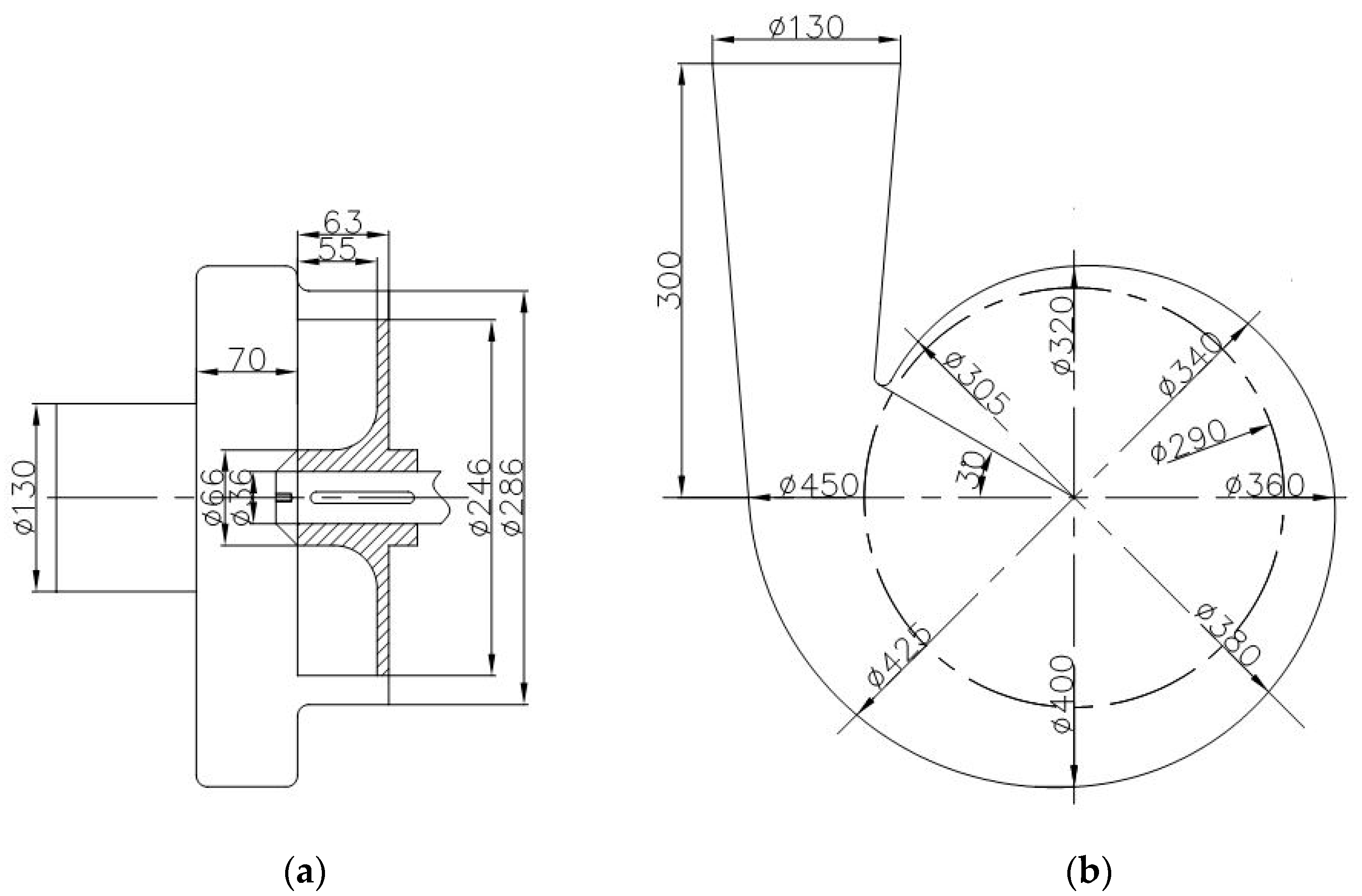
The 150WX-200-20 horizontal vortex pump was selected to establish the model. Its performance parameters were as follows: design flow Qd = 200 m3/h, head He = 20 m, vortex pump rated speed n = 1450 rpm, pump efficiency η = 50%, and shaft power P = 26.34 kW. The hydraulic geometric parameters are listed in Table 1.
The blades of the vortex pump were arranged in a radial array along its axis, and the volute took the form of a semi-helical pressurized water chamber. The two-dimensional hydraulic design of the impeller and volute are shown in Figure 2a,b, respectively.

2.2. Blade Design

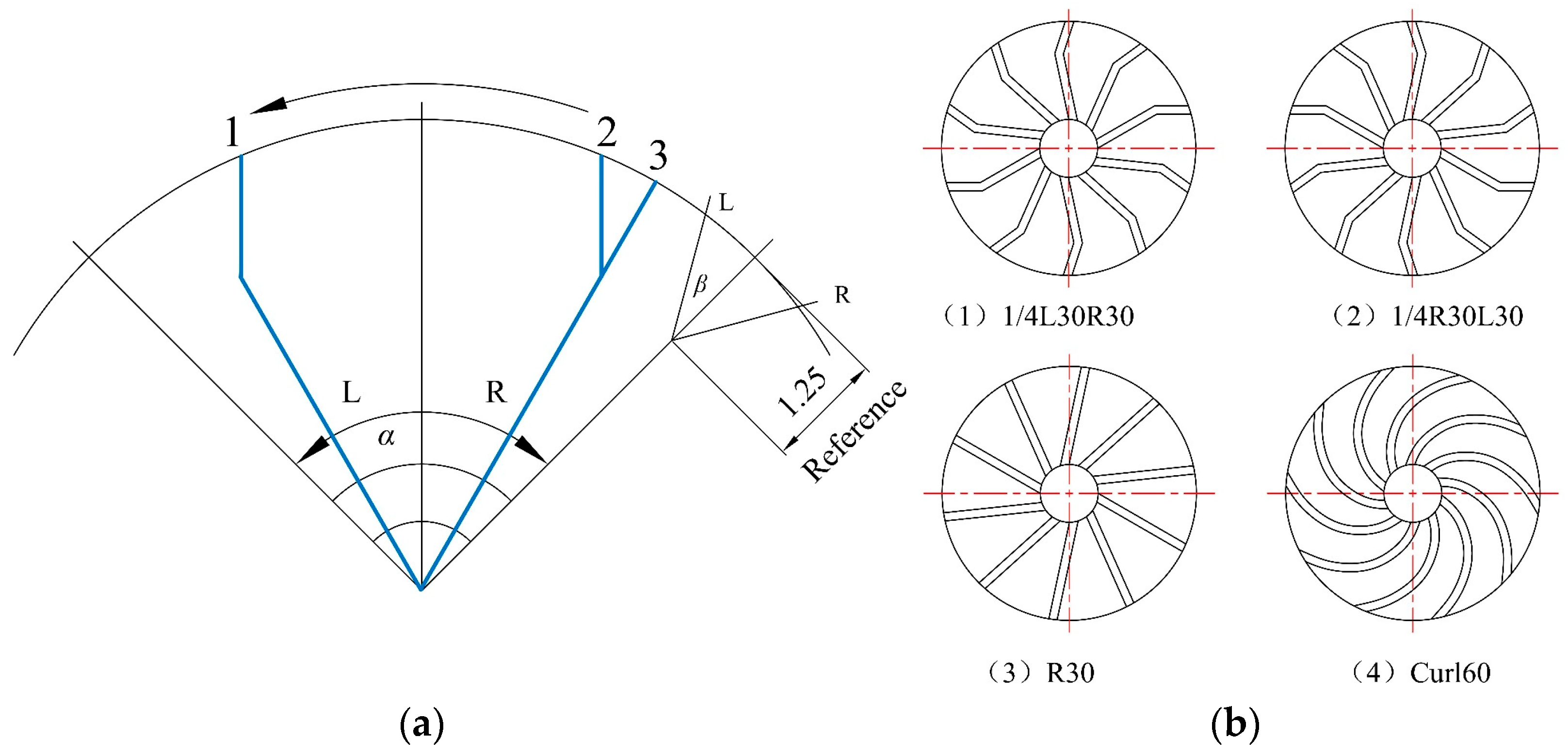
At present, three main types of blades are used in vortex pump impellers: straight, folded, and curved. The blade type is directly related to the performance of the pump [21,22]. In this study, four semi-open blade structures were adopted, as shown in Figure 3b, including a straight blade (R30), two folded blades with a bend at one-quarter to one-third of the full length of the blade (1/4R30L30 and 1/4L30R30), and a curved blade with a wrap angle of 60° (Curl60). A schematic representation of the blade angles is shown in Figure 3a. The oblique angle from the inlet of the blade is denoted by α and the second oblique angle of inclination is denoted by β. For both angles, a prefix “L” indicates that the angle is in the same direction as that of rotation, and a prefix “R” indicates that it is in the reverse direction to that of rotation.

2.3. Model Construction and Meshing

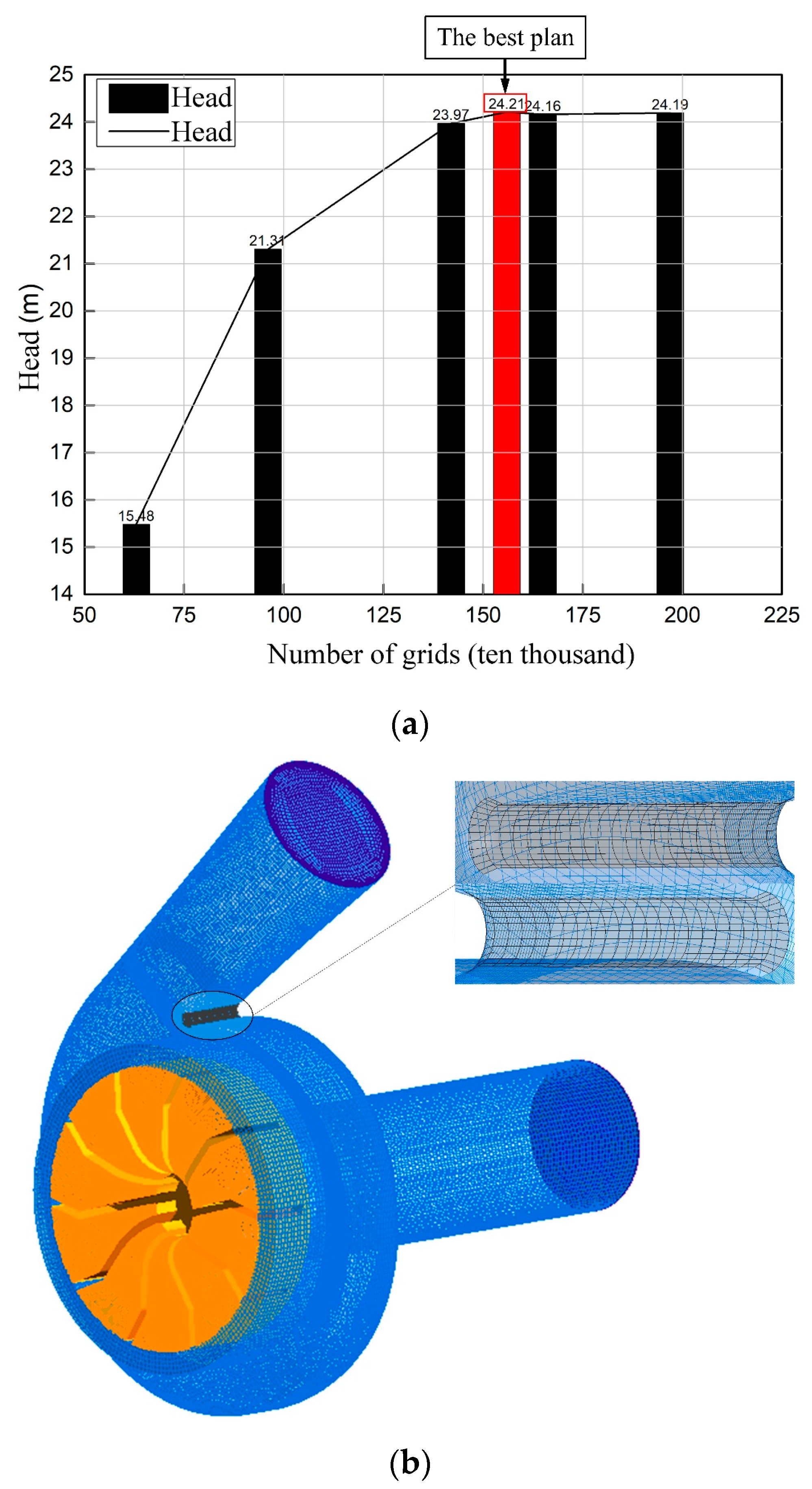
The three-dimensional model of the vortex pump was established in Creo software. The inlet section was extended, and the entire flow field was divided into two parts, namely, the volute domain and the impeller domain as shown in Figure 4. ICEM software was used to mesh the three-dimensional model and check the mesh independence.
The six sets of grids for a vortex pump with a 1/4R30L30 blade were established in a clean water medium. Numerical simulations were performed to verify the grid independence under the design conditions. The change in the head with the number of grids is shown in Figure 5a. When the number of grids is >1.2 × 10⁶, the head changes only slightly, and the influence of the number of grids on the numerical calculation results is small and can be ignored. After comprehensive consideration, a mesh combination method of 1.02 × 10⁶ in the volute area and 5.40 × 10⁵ in the impeller area was adopted. The y+ value of the boundary layer grid was approximately 35. The meshing effect obtained by applying a structured grid is shown in Figure 5b.
Euler two-fluid model was used in the numerical method. The boundary conditions of inlet and outlet were velocity inlet and outflow, respectively. The inlet speed is 1.6 m/s.
A static nonslip wall condition was adopted for the volute and a moving nonslip wall condition for the impeller. Steady-state calculation was adopted for the numerical simulation of the vortex pump. Using the renormalization group (RNG) k-ε turbulence model, the SIMPLEC algorithm, and a second-order upwind discrete format provided a residual accuracy of 10−6. When the residual curve reached the preset accuracy and the outlet pressure was stable, the flow field calculation result was regarded as convergent.

3. Calculation Method

3.1. Determination of Characterization Parameters

3.1.1. Section Selection

The model origin O was defined as the intersection of the symmetry plane of the bladeless cavity and the axis. The positive directions of the x-, y-, and z-axes were, respectively, the direction from the origin to the fourth section of the pressurized water chamber, the direction from the origin along the axis in the direction toward the impeller domain, and the direction of gravitational acceleration as shown in Figure 6. After the coordinate system was established, the bladeless cavity and the impeller domain were divided into equal parts, and these were divided into eight representative research sections.
The definitions and nomenclature of the planes and sections are shown in Figure 6. For example, we named the plane {x = 0}, i.e., the YOZ plane, the X0 plane, and the {y = −20} plane the Y-20 plane to obtain the eight sections.
It should be pointed out that the structure of the flow field in a vortex pump is complex, and only representative cross-sections could be selected for study. To display the streamlines, pressure, volume fraction distribution, and other information about each phase in each cross-section more clearly and intuitively, parts of the CFD output images were cropped to allow key points to be highlighted as shown in the X0 and Z0 sections in Figure 6.

3.1.2. Geometric Characteristics of Circulating Flow

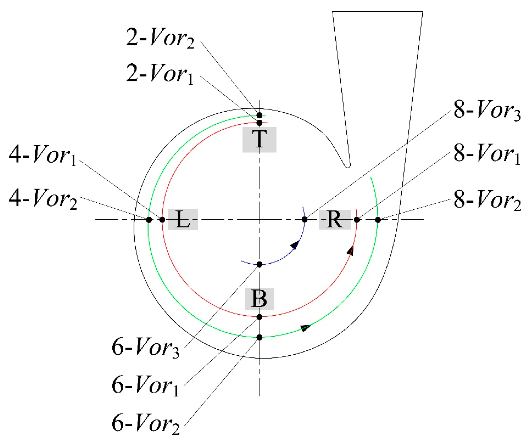
In a solid-liquid two-phase flow, the solid phase moves along with the circulating fluid flow and, thus, when studying the circulating flow in the bladeless cavity, only the flow law for the liquid phase needs to be considered. There is a primary circulating flow I and two secondary circulating flows II and Ⅲ in the pump. The flow structures in each quarter-section of the bladeless cavity are almost the same; therefore, the circulating flow can be simplified to the quarter-axis section, and there are no more than three large-scale vortex structures in each section. The vortex structures at the corresponding positions in each section are connected to form a vortex belt or circulating flow as shown in Figure 7. The geometric characteristics of the vortex structure of the circulating flow on four representative quarter cross-sections were considered to study the circulating flow.
After analysis, a circulating flow appeared in the form of a vortex structure on the X0 and Z0 sections. As shown in Figure 7, the main flow vortex is denoted by Vor1, and the secondary flow vortices are denoted by Vor2 and Vor3. In Figure 8, the red, green, and blue arcs represent the circulating flow structures formed by the Vor1, Vor2, and Vor3 vortex structures, respectively, in the bladeless cavity. When the impeller rotates, the fluid moves along the track “T→L→B→R”, where T, L, B, and R represent the four quarter cross-sections. The vortex structure characteristics on the T and B cross-sections were obtained from the post-processing results of the X0 cross-section, and the L and R cross-sections were derived from the Z0 cross-section.
In the two-phase flow field in the vortex pump, there was not only the overall disordered flow field but also the local regular structure coexisting with it for a long time including connected turbulent fluid mass with instantaneous phase-correlated vorticity over its spatial extent. The interaction of the vortex structures between sections in the bladeless cavity may even lead to the fracture and reconnection of a vortex strip. In this paper, the performance of vortex pumps with different blade profiles were analyzed by discriminating the two-dimensional vortex structures on each section [23,24].

3.2. Description of Geometric and Physical Parameters of the Vortex Structure

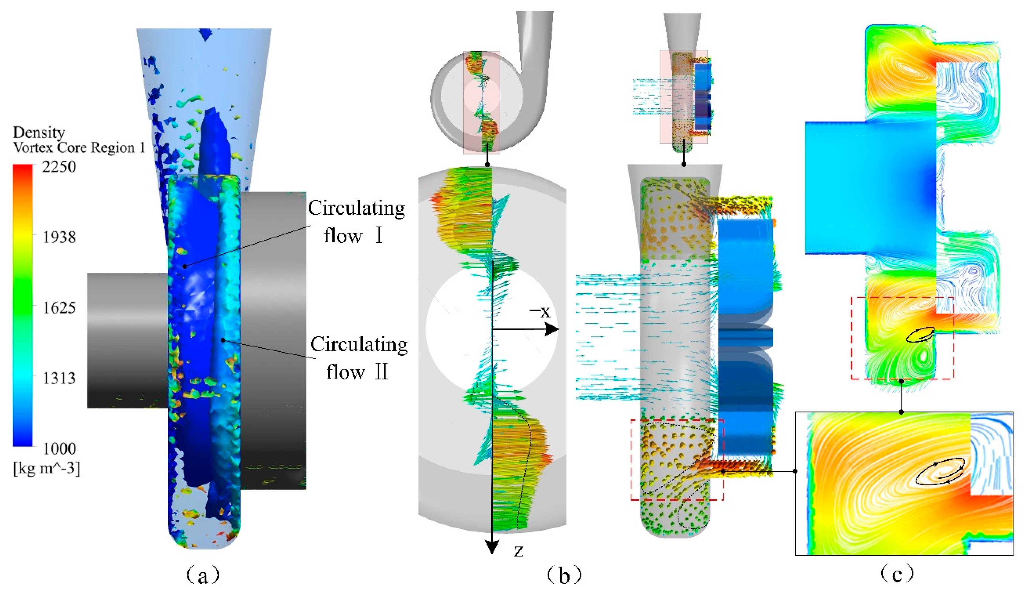
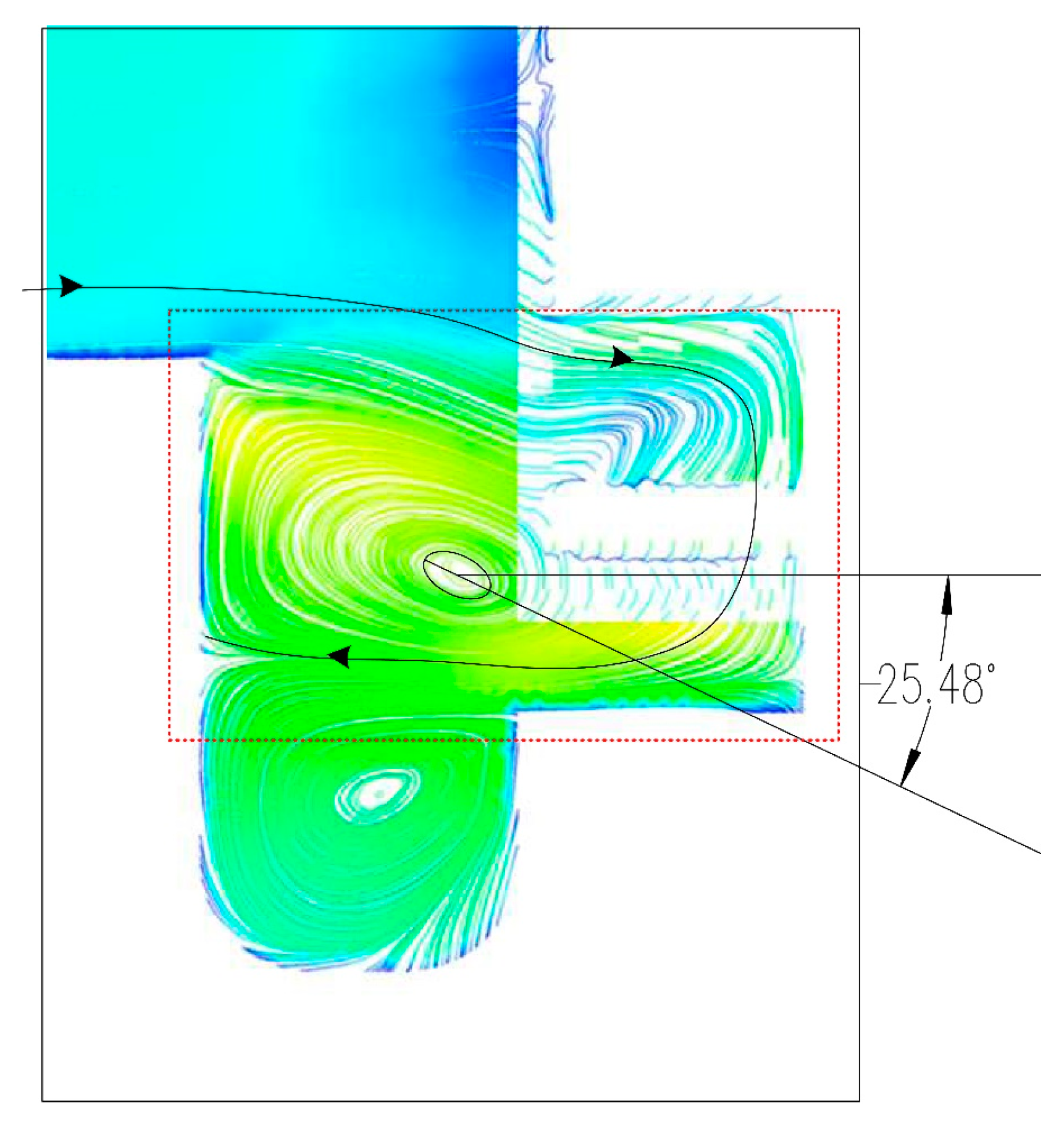
(1) The surrounding fluid flows around the vortex core in an approximately circular motion. Taking the numerical simulation results of a solid volume fraction CV = 10%, particle diameter D = 4 mm, and solid particle density ρ = 2250 kg/m3 as an example, the geometric definition was carried out. As can be seen from the vortex intensity diagram in Figure 9a, there are two vortices rotating around the pump axis in circulating flows I and II in the bladeless cavity. From the liquid-phase vector diagram for the X0 section in Figure 9b, it can be observed that in the dashed area, the direction of the medium velocity vector is almost perpendicular to the section. At the same time, it can be seen from the streamline diagram for this section in Figure 9c that the surrounding fluid flows around a certain position along the axial section. From these results, it is possible to obtain a rough estimate of the position of the vortex core of the vortex structure on the inner shaft section of the pump. One method for estimating the extent of the vortex is based on the center of curvature [25]. In this method, by taking a large number of sample points on a given streamline, the center of curvature of the corresponding circle can be roughly determined. When the streamline, is approximately or exactly a circle, the center of curvature will be located in a relatively small area or at exactly the correct point, respectively. The position of the vortex core is then taken to be in this area or at this point.
The geometric and physical parameters of the circulating flow are thus quantified, and the streamlines near the vortex core are approximated as ellipses. For convenience of analysis, as shown in Figure 10a, the point C is regarded as the vortex core position of the flow field where the streamline is located on the section. The streamline of the XO section is placed in the coordinate system, where the abscissa is y, the ordinate is z, and the distance between the vortex core and the two axes is marked in the coordinate system. The distance between the vortex core and the center surface of the bladeless cavity is set as n, and the distance between the vortex core and the axis is set as m. Because the change in position of the circulating flow in each quarter section in the bladeless cavity is far larger than the error produced by the measurement, this change is obvious, and thus this method can be considered to be valid.
(2) The streamlines near the vortex core are close to elliptical, as can be seen in Figure 10b. Therefore, the eccentricity e (0 < e < 1), which represents the “flatness” of the ellipse, was adopted as a shape coefficient to analyze the variation of the vortex scale of the circulating flow. As shown in Figure 10b, the eccentricity can be calculated from the measured length of the semi-major and semi-minor axes of the ellipse, a and b, respectively. The closer e is to 0, the more nearly circular the shape of the vortex structure; the closer e is to 1, the flatter the vortex structure.
(3) Extending the major axis of the ellipse, as shown in Figure 10c, we took the angle between this axis and the positive direction of the y-axis as the position angle of the vortex core. The deviation between the positive y-axis and the extension of the major axis is shown in Figure 10(c1); the direction of the deviation is positive when it points to the impeller domain. The direction of the deviation is negative if it does not point to the impeller domain as shown in Figure 10(c2).

4. Results and Analysis

For a vortex pump, the medium flows from the inlet end through the bladeless cavity and then enters the impeller region. The direction and velocity of the outflowing medium that has been accelerated in the impeller region have direct effects on the performance of the pump. The flow of the medium in the impeller region is determined by the blade type. There are many types of vortex pump blades. This study considered only straight folded and curved blade types, although both forward and backward folded blades were compared. The effects of the blade shape on the performance of the vortex pump were analyzed.

4.1. Influence of the Blade Shape on the External Characteristics Performance of the Pump

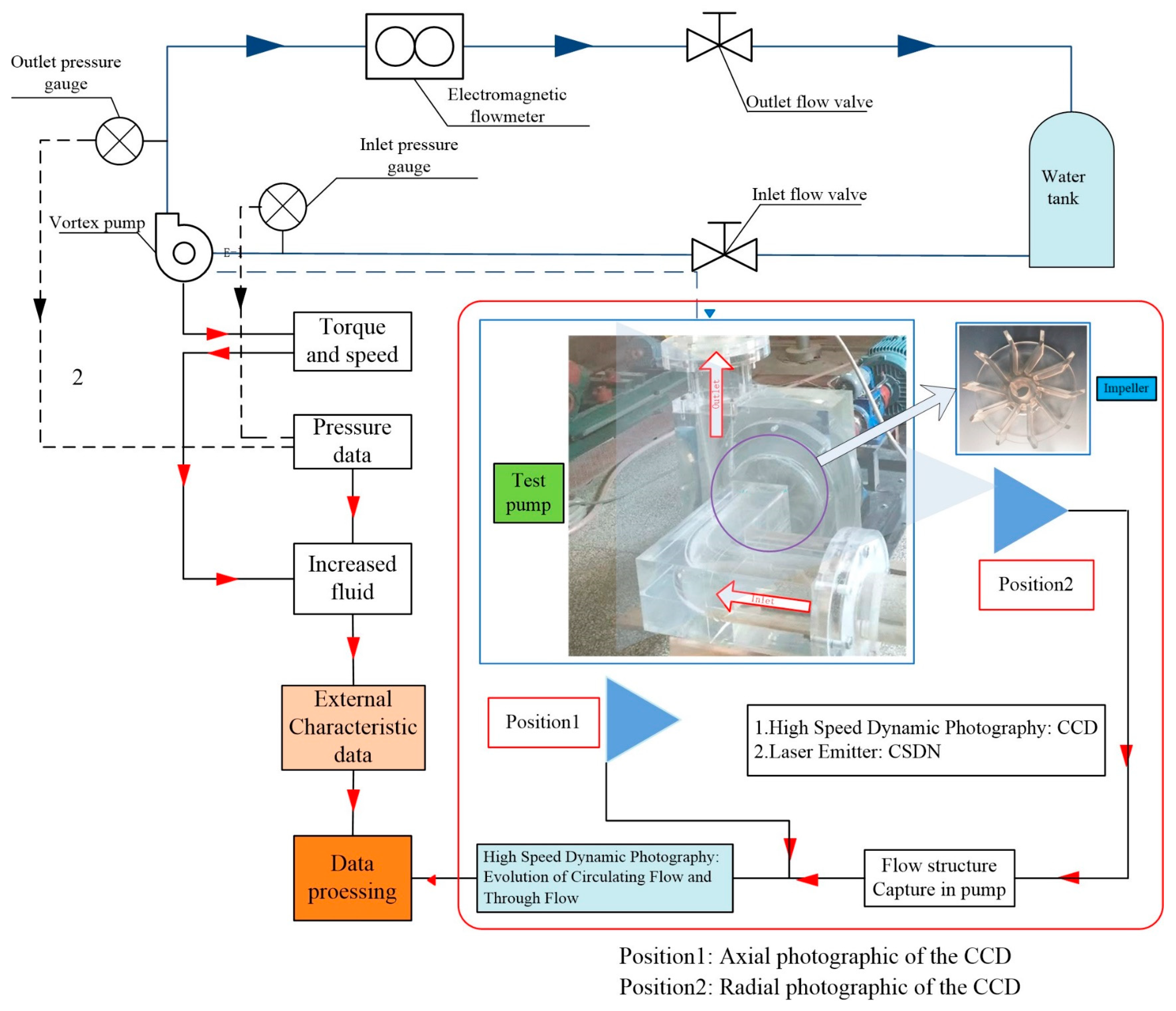
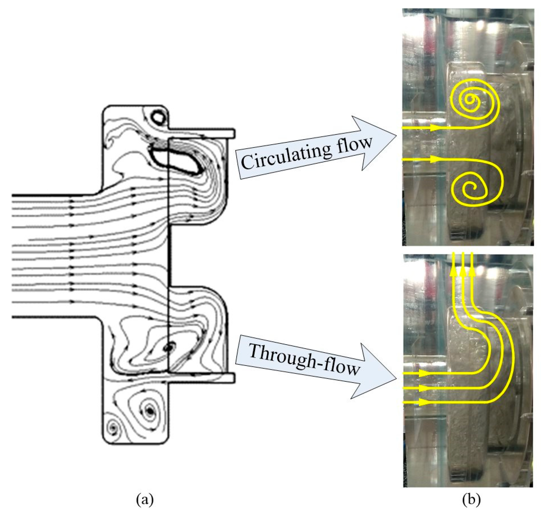
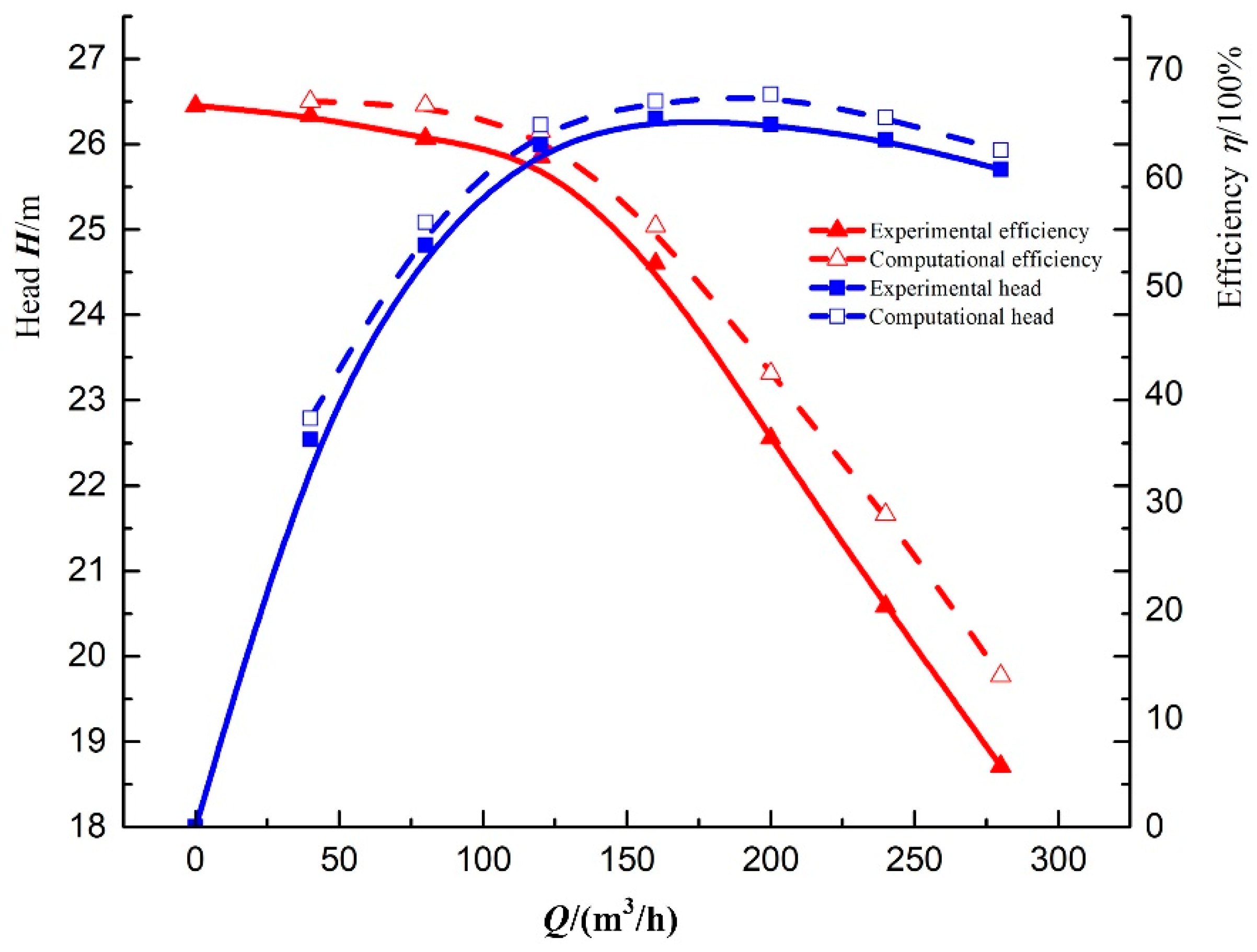
To analyze the internal flow characteristics of the vortex pump and verify the reliability of the numerical simulation, an experimental platform was built for the 150WX-200-20 vortex pump, and an experiment to examine the external characteristics of the pump was conducted. The principle of the experimental platform is shown in Figure 11. The platform used 1/4R30L30 blades. During the experiment, a high-speed camera was used to photograph the internal flow structure in the pump, and the trajectories of the bubbles generated during pump operation were used to trace the fluid trajectory. The internal flow structures of the particles are shown in Figure 12. It can be seen from Figure 12a that the fluid flow from the inlet was initially uniform and parallel, but the fluid trajectory changed after the action of the impeller. It can be seen from Figure 12b that the main forms of fluid motion in the pump were circulating flow and through flow. Pure water medium was used in both experimental and numerical simulations. The external performance curve obtained from the experiments is shown in Figure 13. When the flow changed from 0.2Qd (0.2 times design flow rate) to 1.4Qd, the average errors between the test head Ht and the numerical simulation head Hc and between the test efficiency ηt and the numerical simulation efficiency ηc were 2.27% and 5.26%, respectively. The test results thus demonstrate that the numerical method adopted is reliable for studies of the vortex pump. Therefore, in the subsequent investigations of vortex pump performance, numerical simulations were used instead of experiments, thereby saving time and resources.
For numerically simulated solid-liquid two-phase flow for the four types of blades, the following solid-phase parameters were adopted: solid particle density ρ = 2250 kg/m3, particle size = 4 mm, and solid-phase volume fraction Cv = 10%. Numerical simulations of the flow under five working conditions ranging from 0.6Qd to 1.4Qd were performed.
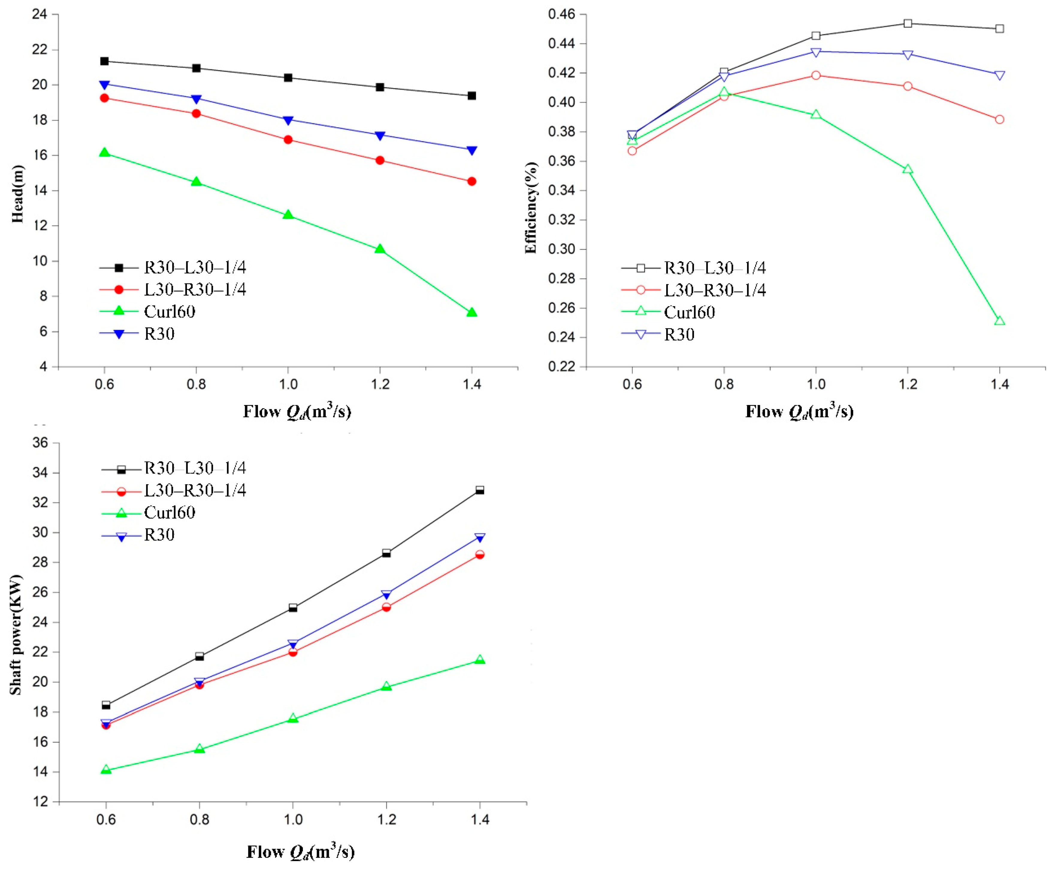
Figure 14 shows a comparison of performance of the vortex pump with the same solid-liquid two-phase flow for the four different impeller blade types: 1/4R30L30, R30, 1/4L30R30, and Curl60. The four types of blades had different high-efficiency points. Under the rated conditions, the performance of the front-bent 1/4R30L30 blade was far superior to those of the other blade types. The straight R30 blade had the next highest efficiency, followed by the rear-bent 1/4L30R30 blade and finally the curved Curl60 blade. It can be seen that the efficiency of the curved blade peaked at 0.8Qd and then dropped dramatically with further increases in the flow rate, and its maximum head was lower than that of the other blades. It can be noted that when the direction of deflection of the impeller blade was opposite to the direction of its angular velocity, the performance of the vortex pump was generally better.

4.2. Effect of Blade Shape on Circulating Flow in the Bladeless Cavity

4.2.1. Effect of Blade Shape on Vortex Core Position

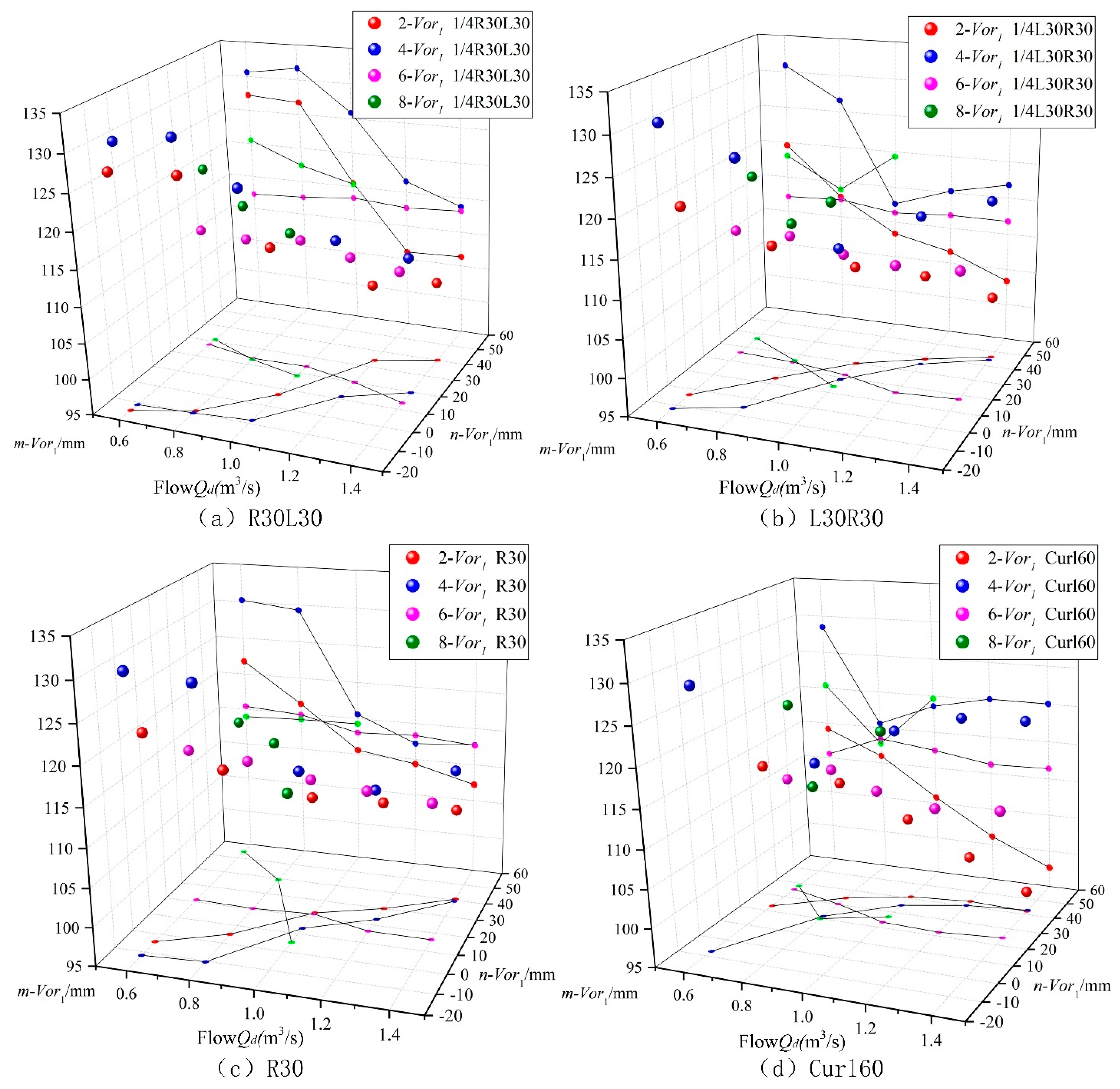
As shown in Figure 15, different blade shapes had a greater impact on the position of the vortex core of the 2-, 4-, 6-, and 8-Vor1 vortex structures in the vortex pump. At the same time, the position of the vortex core changed with an increasing flow rate, and there was no obvious 8-Vor1 structure after 1.2Qd. The vortex cores for blade types 1/4R30L30 and R30 moved in the same way. In the y direction, with increasing flow rate, both 2-Vor1 and 4-Vor1 increased, whereas both 6- and 8-Vor1 decreased. In the z direction, with an increasing flow rate, 2-, 4-, 6-, and 8-Vor1 for 1/4R30L30 all decreased, 8-Vor1 for R30 increased slightly, and 2-, 4-, and 6-Vor1 showed the same trend as 1/4R30L30. Before and after the operating point, the vortex core position tended to change for both 1/4L30R30 and Curl60. For 1/4L30R30, the z coordinates of 4- and 8-Vor1 first decreased and then increased at 1.0Qd and 0.8Qd, respectively. The 4-, 6-, and 8-Vor1 structures for Curl60 appeared at the best operating point of 0.8Qd, where the z coordinate first dropped and then rose.
The circulating flow distance is represented by the position of the vortex core in the section of the bladeless cavity. When the vortex core was closer to the bladeless cavity, the flow was disrupted by the force of the impeller rotation. After the vortex was reduced in size, it absorbed energy in the bladeless cavity and thereby reduced the performance of the vortex pump. The vortex pump attained its highest working condition when all vortex cores in all sections left the impeller region or were at a large distance from it. The position of the vortex core directly affected the head and efficiency of the pump. At the point of highest efficiency, the positions of the four vortex structures (for which there were three or four vortex cores) were all inside the bladeless cavity (n-Vor1 < 35 mm).

4.2.2. Influence of Blade Shape on Vortex Shape

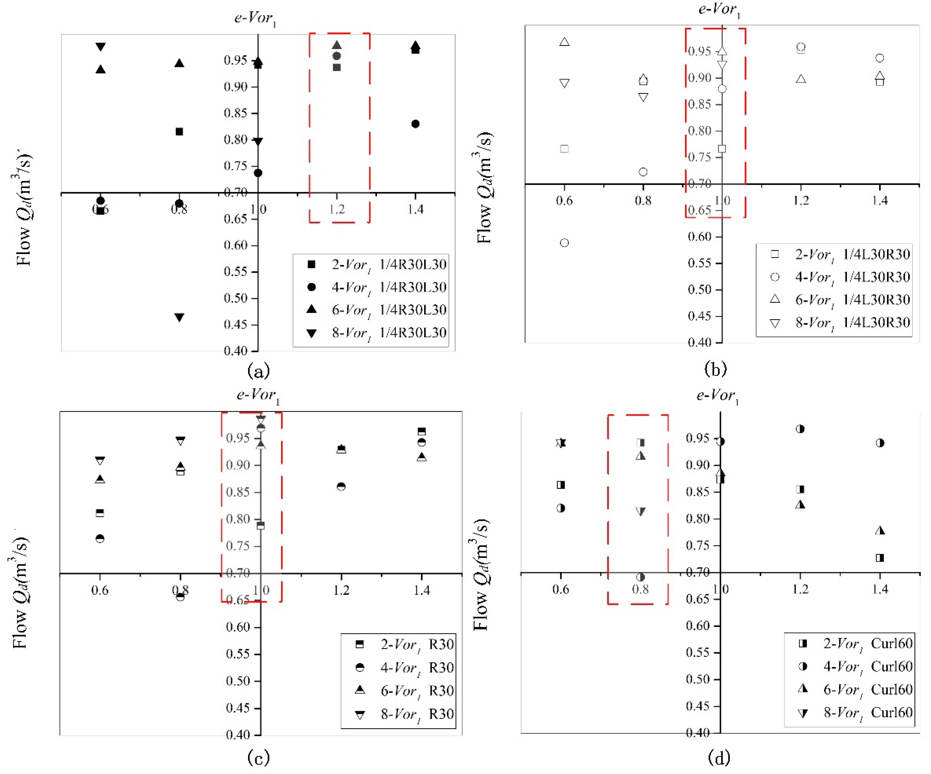
By performing numerical simulations for the four blade types, we determined the values of the eccentricities e-2-Vor1, e-4-Vor1, e-6-Vor1, and e-8-Vor1 for each blade type under the five working conditions (from 0.6Qd to 1.4Qd). The variations of these eccentricities with the flow rate are shown in Figure 16.
It can be observed from Figure 16 that 4-Vor1 of 1/4R30L30 and Curl60 and 2-Vor1 of R30 and 1/4L30R30 all had a smaller eccentricity at the high-efficiency point. The greater the eccentricity of 2-Vor1 at the high-efficiency point, the better the performance of the vortex pump. At the high-efficiency point, 2-Vor1 was not only squeezed by the through flow but was also affected by the free vortex at the separation tongue. A higher value of eccentricity means that the circulating flow is less disturbed, which is more conducive to transport of the medium. As the cross-sectional area of the bladeless cavity increased, the shape coefficient of the circulating flow also changed during the development process. When the vortex core was close to the interface between the bladeless cavity and the impeller domain, the vortex structure became slightly rounded. When the vortex core entered the impeller, the vortex structure after the impeller domain became flat. When the shape of the vortex structure in the bladeless cavity was stable within a certain range (i.e., the difference between the maximum and minimum eccentricities was 0.2–0.25, and the difference between the maximum eccentricity and the next highest value was less than 0.05), the efficiency of the vortex pump was highest.

4.2.3. Influence of the Blade Shape on the Vortex Core Position Angle

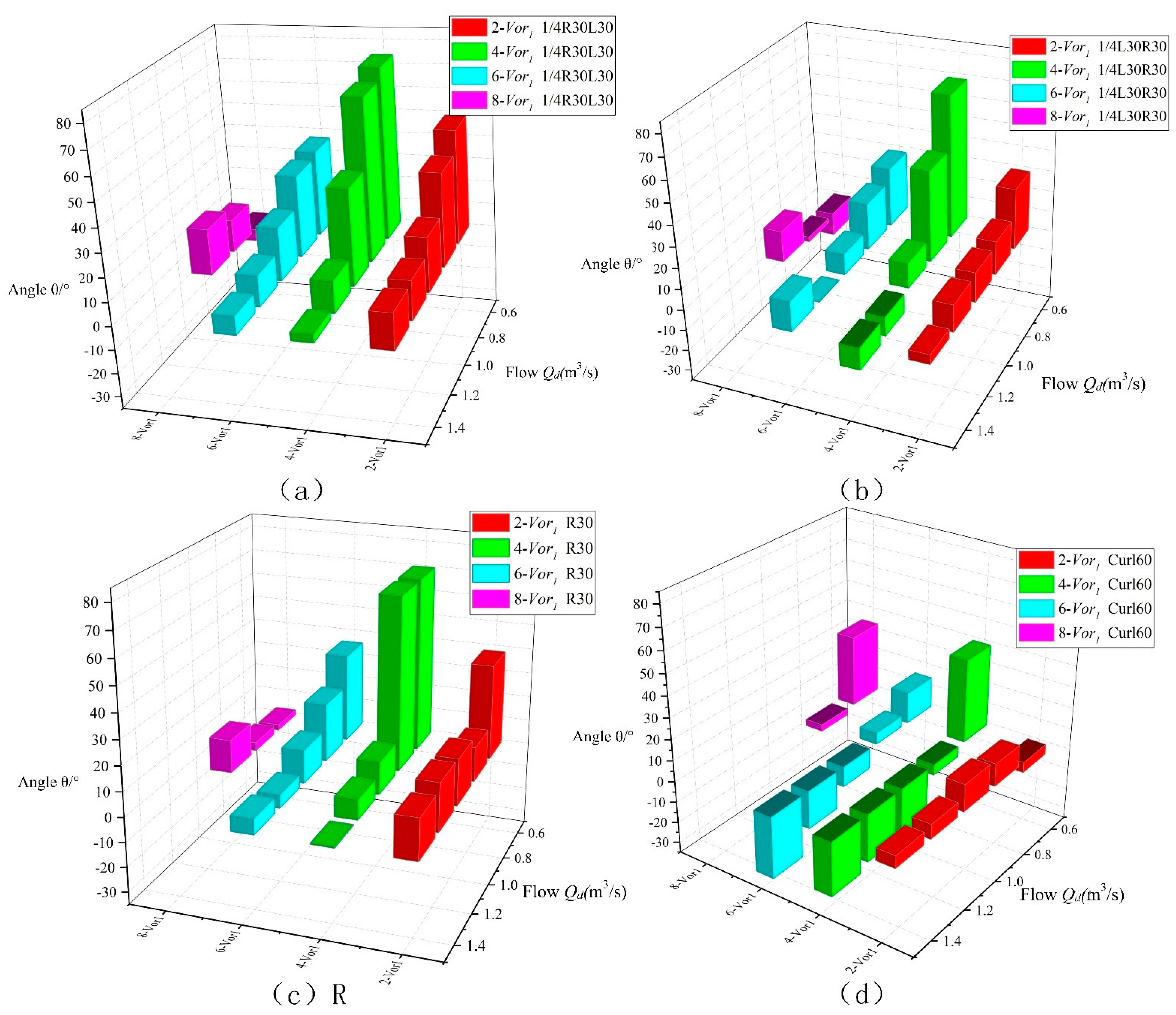
As shown in Figure 17, regardless of the blade type at the highest operating point, the values of the vortex core position angle θ-Vor1 were relatively close to each other. The variation of θ-Vor1 was basically the same for the different blade types. With increasing flow, θ-2-, θ-4-, and θ-6-Vor1 all decreased, and θ-8-Vor1, except for the curved blade Curl60, all increased. At the optimal operating point, the greater the fluctuation range of θ-Vor1, the better the performance of the vortex pump with the corresponding blade.
The front bent blade 1/4R30L30 was closest in behavior to the straight blade R30. The θ-Vor1 values of these two blade types exhibited similar variations under most working conditions, although the range over which R30 decreased fluctuated greatly. This indicates that with the straight blade, there was poor control over the circulating flow. By contrast, the second angle of the bent blade 1/4R30L30 had a beneficial impact on the performance of the vortex pump and allowed for better control of the circulating flow. In contrast to the R30 blade, the other three blade types exhibited negative θ-Vor1 values, especially the curved blade Curl60 and the back-bent blade 1/4L30R30.
As shown in Figure 18, when θ-Vor1 is negative, the flow direction of the medium pumped by the impeller was parallel to the axis. In this case, the angle between through flow-Vor1, through flow-Vor2, and through flow and the positive y-axis were, respectively, θ1, θ2, and θ, and were all approximately 0°. Part of the through flow hit the left sidewall of the bladeless cavity and part of it merged into Vor2, and this consumed considerable energy, which degraded the performance of the pump. The direction in which the fluid flowed out after being accelerated by the impeller was directly related to the efficiency. When the angle of the vortex scale extension was larger, the efficiency of the pump with the corresponding blade type was higher.

5. Conclusions

(1) The four types of blades can be arranged in order of decreasing performance as follows: 1/4R30L30, R30, 1/4L30R30, and Curl60. The flow of the medium in the impeller area had a direct effect on the variations in flow structure in the bladeless cavity, thereby affecting the external characteristics of the pump;
(2) The vortex core position of the vortex structure in each section of the bladeless cavity directly affected the performance of the vortex pump. The greater the circulating flow range, the poorer the performance. The pump reached its highest working condition when and only when all the vortex cores of the vortex structure in all sections had left the impeller domain and were far from it. The farther a vortex core was from the y-axis, the less likely it was to approach the impeller, and the higher the efficiency of the pump;
(3) For the different blade shapes, the values of the eccentricities e-2-Vor1, e-4-Vor1, e-6-Vor1, and e-8-Vor1 at the cross-section of the bladeless cavity were related to the performance of the pump. Because of the squeezing of the through flow, the greater the eccentricity of 2-Vor1 at the high-efficiency point, the better the performance;
(4) Under different blade types, the flow velocity and vector direction of the medium leaving the impeller after the impeller accelerated under the same operating conditions were different, resulting in different circulating flow structures in the bladeless cavity. When the vortex core representing the position of circulating flow at the high efficiency point had not entered the impeller domain but was close enough, the larger the position angle of the vortex core and the higher the efficiency of the vortex pump of this blade type.

Author Contributions

Data curation and writing—original draft, H.Q. and Y.L.; supervision, L.K. and X.Y.; writing—review and editing, K.S. and Y.W. All authors have read and agreed to the published version of the manuscript.

Funding

This work was partially supported by the National Natural Science Foundation of China (NSFC) (51969014, 51609113), the China Postdoctoral Science Foundation (2018M633651XB), the Natural Science Foundation of Gansu (20JR5RA456), the Outstanding Young Talents Funding Scheme of Gansu province (20JR10RA204), the Hong Liu Outstanding Young Talents Funding Scheme of Lanzhou University of Technology.

Institutional Review Board Statement

Not applicable.

Informed Consent Statement

Not applicable.

Data Availability Statement

The data presented in this study are available on request from the corresponding author.

Conflicts of Interest

The authors declare no conflict of interest.

References

  1. Lu, Z.; Tao, R.; Jin, F.; Li, P.; Xiao, R.; Liu, W. The Temporal-Spatial Features of Pressure Pulsation in the Diffusers of a Large-Scale Vaned-Voluted Centrifugal Pump. Machines 2021, 9, 266. [Google Scholar] [CrossRef]
  2. Wang, H.; Long, B.; Wang, C.; Han, C.; Li, L. Effects of the impeller blade with a slot structure on the centrifugal pump performance. Energies 2020, 13, 1628. [Google Scholar] [CrossRef]
  3. Gao, X.; Shi, W.; Zhao, R.; Zhao, T.; Wang, H.; Mucka, P. Optimization Design and Internal Flow Field Study of Open-Design Vortex Pump. Shock Vib. 2021, 2021, 1–11. [Google Scholar] [CrossRef]
  4. Quan, H.; Chai, Y.; Li, R.; Guo, J. Numerical simulation and experiment for study on internal flow pattern of vortex pump. Eng. Comput. 2019, 36, 1579–1596. [Google Scholar] [CrossRef]
  5. Gerlach, A.; Thamsen, P.; Wulff, S.; Jacobsen, C. Design Parameters of Vortex Pumps: A Meta-Analysis of Experimental Studies. Energies 2017, 10, 58. [Google Scholar] [CrossRef] [Green Version]
  6. Ju, Y.-P.; Liu, S.; Zhang, C.-H. Effect of blade shape on hydraulic performance and vortex structure of vortex pumps. J. Hydrodyn. 2018, 30, 499–506. [Google Scholar] [CrossRef]
  7. Li, W.; Zhang, Y. The Vortex Pump under Highly Viscous Liquid Flow Conditions. Arab. J. Sci. Eng. 2018, 43, 4739–4761. [Google Scholar] [CrossRef]
  8. Zhou, J.; Zhao, M.; Wang, C.; Gao, Z. Optimal design of diversion piers of lateral intake pumping station based on orthogonal test. Shock Vib. 2021, 6616456. [Google Scholar] [CrossRef]
  9. Li, W. Vortex Pump as Turbine—A Type Turbine for Energy Generation or Recovery Based on Computational Fluid Dynamics Prediction. J. Fluids Eng. 2019, 141, 15. [Google Scholar] [CrossRef]
  10. Wang, H.; Hu, Q.; Yang, Y.; Wang, C. Performance differences of electrical submersible pump under variable speed schemes. Int. J. Simul. Model. 2021, 20, 76–86. [Google Scholar] [CrossRef]
  11. Steinmann, A.; Wurm, H.; Otto, A. Numerical and experimental investigations of the unsteady cavitating flow in a vortex pump. J. Hydrodyn. Ser. B 2010, 22 (Suppl. 1), 324–329. [Google Scholar] [CrossRef]
  12. Ye, D.; Li, H.; Ma, Q.; Han, Q.; Sun, X. Numerical Investigation of Performance Improvement and Erosion Characteristics of Vortex Pump Using Particle Model. Shock Vib. 2020, 2020, 1–10. [Google Scholar] [CrossRef]
  13. Mihalić, T.; Guzović, Z.; Predin, A. CFD flow analysis in the centrifugal vortex pump. Int. J. Numer. Methods Heat Fluid Flow 2014, 24, 545–562. [Google Scholar] [CrossRef] [Green Version]
  14. Gerlach, A.; Preuss, E.; Thamsen, P.U.; Lykholt-Ustrup, F. Numerical simulations of the internal flow pattern of a vortex pump compared to the Hamel-Oseen vortex. J. Mech. Sci. Technol. 2017, 31, 1711–1719. [Google Scholar] [CrossRef]
  15. Chen, H.-X. Research on turbulent flow within the vortex pump. J. Hydrodyn. 2004, 16, 701–707. [Google Scholar]
  16. Gao, X.; Shi, W.; Shi, Y.; Chang, H.; Zhao, T. DEM-CFD Simulation and Experiments on the Flow Characteristics of Particles in Vortex Pumps. Water 2020, 12, 2444. [Google Scholar] [CrossRef]
  17. Zhang, L.; Wang, C.; Zhang, Y.; Xiang, W.; He, Z.; Shi, W. Numerical study of coupled flow in blocking pulsed jet impinging on a rotating wall. J. Braz. Soc. Mech. Sci. Eng. 2021, 43, 508. [Google Scholar] [CrossRef]
  18. Shi, L.; Zhu, J.; Tang, F.; Wang, C. Multi-Disciplinary optimization design of axial-flow pump impellers based on the approximation model. Energies 2020, 13, 779. [Google Scholar] [CrossRef] [Green Version]
  19. Lucius, A.; Brenner, G. Numerical Simulation and Evaluation of Velocity Fluctuations During Rotating Stall of a Centrifugal Pump. J. Fluids Eng. 2011, 133, 8. [Google Scholar] [CrossRef]
  20. Quan, H.; Guo, Y.; Li, R.N.; Su, Q.M.; Chai, Y. Optimization design and experimental study of vortex pump based on orthogonal test [Review]. Sci. Prog. 2020, 103, 20. [Google Scholar] [CrossRef] [PubMed] [Green Version]
  21. Quan, H.; Cheng, J.; Guo, Y.; Kang, L.; Peng, G. Influence of Screw Centrifugal Inducer on Internal Flow Structure of Vortex Pump. J. Fluids Eng. 2020, 142, 9. [Google Scholar] [CrossRef]
  22. Wang, H.; Qian, Z.; Zhang, D.; Wang, T.; Wang, C. Numerical study of the normal impinging water jet at different impinging height, based on Wray–Agarwal turbulence model. Energies 2020, 13, 1744. [Google Scholar] [CrossRef] [Green Version]
  23. Jeong, J.; Hussain, F. On the identification of a vortex. J. Fluid Mech. 1995, 285, 69–94. [Google Scholar] [CrossRef]
  24. Mariotti, A.; Galletti, C.; Salvetti, M.V.; Brunazzi, E.J.I.; Research, E.C. Unsteady Flow Regimes in a T-Shaped Micromixer: Mixing and Characteristic Frequencies. Ind. Eng. Chem. Res. 2019, 58, 29. [Google Scholar] [CrossRef]
  25. Xu, H.; Cai, X.-S.; Liu, C. Liutex (vortex) core definition and automatic identification for turbulence vortex structures. J. Hydrodyn. 2019, 31, 857–863. [Google Scholar] [CrossRef]
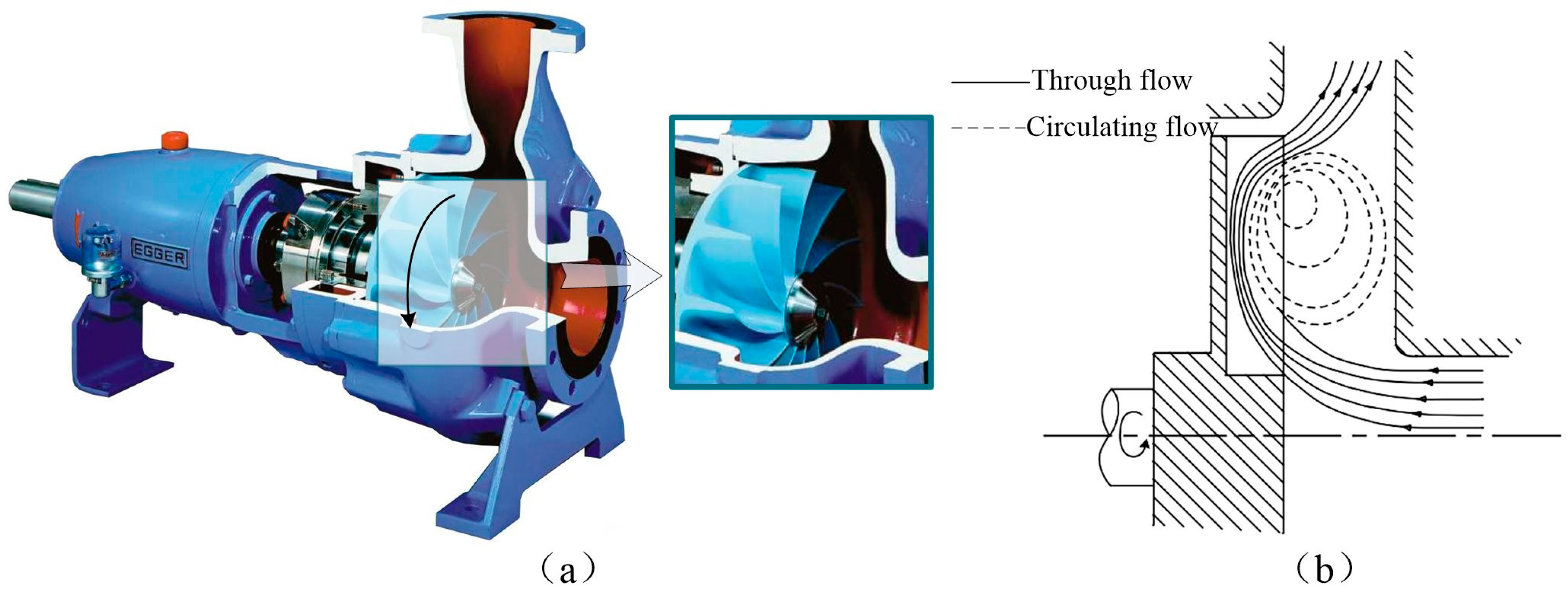
Figure 1. Schematic diagram of vortex pump and flow structure: (a) vortex pump structure diagram; (b) schematic diagram of flow structure of vortex pump.
Machines 09 00353 g001
Figure 2. Hydraulic design drawing of vortex pump: (a) vortex pump structure design diagram; (b) volute hydraulic design.
Machines 09 00353 g002
Figure 3. Blade shape design: (a) schematic diagram of blade angle; (b) four blade types.
Machines 09 00353 g003
Figure 4. Area division diagram of the vortex pump.
Machines 09 00353 g004
Figure 5. Schematic diagram of grid independence check and computational domain grid: (a) grid independence check; (b) schematic diagram of the computational domain grid.
Machines 09 00353 g005
Figure 6. Cross-section selection scheme.
Machines 09 00353 g006
Figure 7. Schematic diagram of the circulating flow distribution.
Machines 09 00353 g007
Figure 8. Existence of a vortex structure on each section in the vortex pump.
Machines 09 00353 g008
Figure 9. Schematic diagram of vortex discrimination: (a) cortex intensity diagram; (b) liquid—phase vector diagram for the X0 section; (c) streamline diagram.
Machines 09 00353 g009
Figure 10. Schematic diagram of the position, shape, and angle of the vortex structure: (a) definition of the vortex core position; (b) vortex core shape and eccentricity calculation; (c1) the positive angle of the vortex core; (c2) the negative angle of the vortex core.
Machines 09 00353 g010
Figure 11. Schematic diagram of the experimental platform.
Machines 09 00353 g011
Figure 12. Fluid motion state diagram in the vortex pump: (a) streamline of the numerical simulation; (b) the internal flow structure in the pump.
Machines 09 00353 g012
Figure 13. Hydraulic performance error verification.
Machines 09 00353 g013
Figure 14. Performance curves of vortex pumps under different blade types.
Machines 09 00353 g014
Figure 15. The position change of the vortex core in the bladeless cavity with different blade shapes: (a) the position change of the vortex core in 1/4R30L30; (b) the position change of the vortex core in 1/4L30R30; (c) the position change of the vortex core in R30; (d) the position change of the vortex core in Curl60.
Machines 09 00353 g015
Figure 16. Variations of the shape coefficient of the vortex structure with different blade shapes: (a) the eccentricity of 1/4R30L30; (b) the eccentricity of 1/4L30R30; (c) the eccentricity of R30; (d) the eccentricity of Curl60.
Machines 09 00353 g016
Figure 17. Changes in the angle θ between the vortex structure and the axial direction of different blade shape: (a) changes of the angle θ in 1/4R30L30; (b) changes of the angle θ in 1/4L30R30; (c) changes of the angle θ in R30; (d) changes of the angle θ in Curl60.
Machines 09 00353 g017
Figure 18. The flow of the vortex structure and through flow when θ-Vor1 was negative.
Machines 09 00353 g018
Table 1. Vortex pump hydraulic geometric parameters.
Impeller Hydraulic Geometric ParametersVolute Hydraulic Parameters
Impeller outer diameter, D2/mm246Volute width, L/mm70
Impeller width, b/mm60The bladeless cavity base circle, D3/mm290
Number of blades, Z10Clearance between impeller outer
diameter and shell, e/mm
20
Blade thickness, b2/mm8The bladeless cavity throat area, Fthr/cm2110
Publisher’s Note: MDPI stays neutral with regard to jurisdictional claims in published maps and institutional affiliations.