1. Introduction
The reduction of energy prices and carbon emissions is vital for the modern world that needs to cut poverty and stop global warming. Wind turbines (WTs) are an important contributor towards energy production free of CO2, and associated condition monitoring systems have a key role in their availability, ultimately, driving the reduction of the cost of energy.
Since the 1990s, various wind turbine concepts and control techniques have been developed for maximizing the reliability and efficiency while reducing overall cost. State-of-the art and emerging technologies towards more efficient wind turbines are reviewed in [
1,
2,
3,
4,
5]. Among these, the direct drive technology has assumed an important role in the wind offshore industry with low speed and high torque permanent magnet synchronous generators (PMSGs).
Condition monitoring and fault diagnosis are considered effective tools to detect incipient failures and generate early fault alarms, assuming a paramount importance in reducing operational and maintenance (O&M) costs. O&M costs have a significant contribution from unforeseen drive train failures and account for up to 25% of the total levelized cost of electricity [
6]. The generator is a reliable component of a wind turbine, but its failure causes long downtimes and high economic losses, which serves as motivation for developing CM methods.
This paper reviews the state-of-the-art in fields of fault detection (FD) and condition monitoring (CM) of PMSGs for wind turbine applications. Stator insulation failures are found as the most critical ones without mature methods to meet wind industry’s needs. Accordingly, insulation failures are emphasized the most throughout this review, whereas others are discussed more lightly—high resistance connection of stator windings, airgap eccentricity, and demagnetization of permanent magnets.
2. Fault Detection and Condition Monitoring
In depth explanation of condition monitoring related concepts and terminology for rotating electrical machines can be found in [
7,
8]. A brief introduction is given here for the benefit of the reader. In fact, terms like failure, fault, fault detection, and condition monitoring are commonly (mis-)used in the wind industry across teams of data scientists, mechanical, electrical, and system engineers.
Failure is defined as the time/event when the electrical generator stops to perform its function of energy conversion. Failure is complete and does not imply partial functionality. Failure mode is how generator failure occurred (e.g., stator winding insulation failure). Failure root cause is how the failure mode was initiated (e.g., production defect). Fault is an abnormal condition or defect that may lead to a failure.
Fault detection (protection) is designed to detect faults as they occur and to initiate executive action that minimizes damage before failure. The executive action may be disconnection from the power supply or switch to a safe operating mode. Electrical faults and failures may coincide in time (e.g., phase-to-ground short-circuit fault and winding failure) making these terms interchangeable (sometimes confused by electrical engineers), whereas a mechanical fault may precede failure by months or years (e.g., a broken tooth is a gearbox fault that progressively leads to its complete failure).
Condition monitoring (CM) aims to derive methods to measure and assess continuously parameters (features) that indicate degradation and provide early warning of future failure. Ideally, selected parameters develop slowly over time and address the failure root cause as closely as possible. Accordingly, CM focus on predicting failures, enabling estimation of the remaining useful life (RUL) and condition-based maintenance of wind turbine components.
Both FD and CM are intended for continuous evaluation of equipment throughout its serviceable life. Fault detection is important to stop infant failures (e.g., production errors, foreign objects, contamination, etc.), whereas condition monitoring is most relevant for machines approaching the design lifetime or under accelerated ageing conditions (high capacity factors, temperatures and vibrations). Even though CM, FD and protection functions are closely related, implementation approaches may differ considerably. If the same method is employed for fault detection and condition monitoring, caution is required to ensure robustness against false alarms. Many methods traditionally adopted for fault protection prove unfit for condition monitoring. Successful CM provides failure prognosis (as early as possible) that is used to plan service interventions and minimize unscheduled stops and downtime, thus, improving availability and profitability. Concerning generator electrical failures, a large number of published methods fail to meet this success criteria. In addition to increasing availability, condition-based maintenance spares the investment in stock of spare components with long lead times.
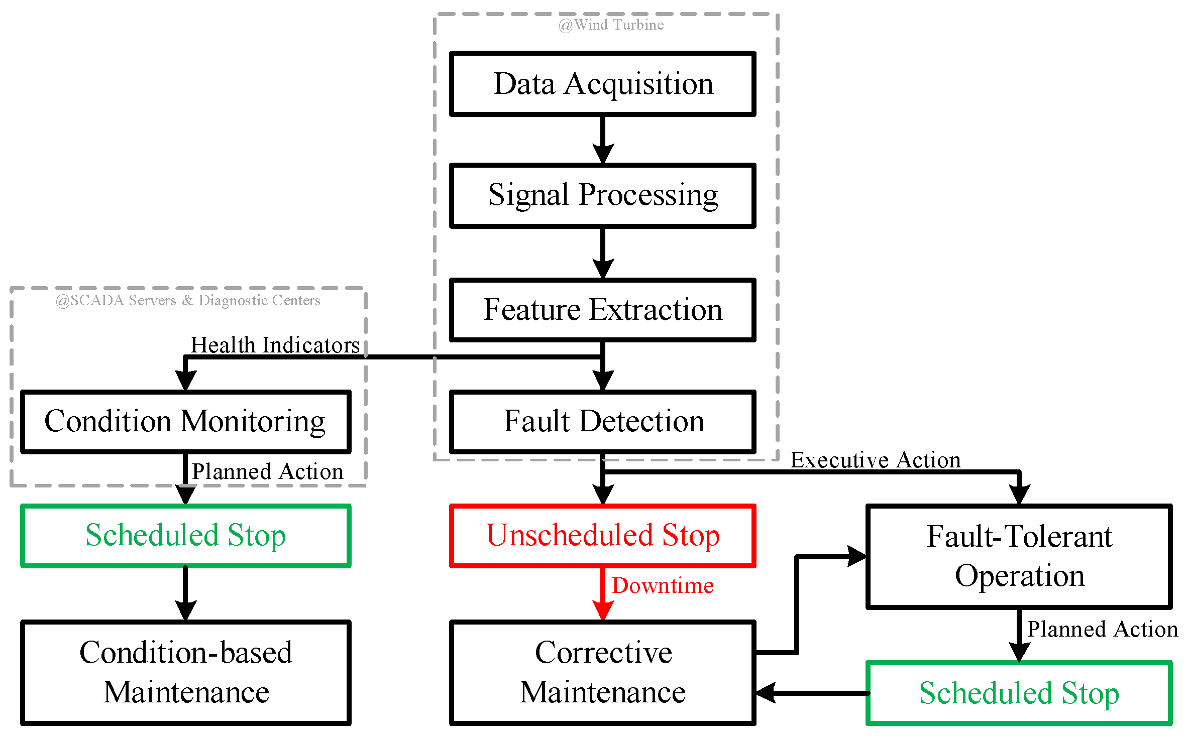
Figure 1 shows that CM and FD start at the turbine level with a conceptually similar process flow, where health indicators are derived from various sources (sensors, controllers, and CM system) at relatively high sampling rates. CM continues at supervisory control and data acquisition (SCADA)/cloud servers and diagnostics centers, where methods are deployed for failure prognosis. As a result, service actions are planned as per the predicted time of failure, preventing unscheduled stops and reducing downtime. FD runs at the turbine for fast executive actions—in parallel with CM, triggering either a stop or a fault-tolerant operating mode. Thus, downtime can be avoided only if the drive train component being monitored is endowed with fault-tolerant capabilities, which may allow uninterrupted operation or an unscheduled stop of short duration. Fault-tolerant operation may be initiated automatically by means of software reconfigurations (e.g., changing operating limits), or manually after corrective maintenance takes places (e.g., disconnections of faulty circuits). However, the design of fault-tolerant systems may impact cost and performance of a wind turbine, making these approaches less attractive.
With the aid of
Figure 1, it must have become evident to the reader that requirements and benefits differ between CM and FD. The effort spent in CM to recognize fault development as early as possible is motivated by the need for cost-effective preventive and condition-based maintenance approaches, having the potential to eliminate unscheduled service/stops—obviously more valuable than emergency shutdowns just before catastrophic failure. Condition-based maintenance is a process of planning optimal and timely maintenance based on machine condition information obtained through CM. As an example, operators may choose to run a faulty generator till failure to reduce production losses, while a replacement is manufactured and shipped to site. A major offshore repair—generator replacement—often takes several weeks from planning to execution.
Ideally, CM is deployed by exploiting existing sensors (used for control and protection) and data (dark data) for minimum cost of implementation. However, this is often unfeasible, and the CM system operates in standalone. Better integration of CM systems with turbines controllers may improve performance and reduce costs. The cost of CM hardware becomes the first barrier to the adoption of innovative technologies. An assessment of the business case is required to justify the investment in CM, taking into consideration costs of repair or replacement and downtime. An attractive business case is much more likely to be found for large MW generators with long lifetime expectancy. Thus, new offshore turbines and their generators are good candidates due to difficult access, long lead times, and costly operations (logistics— Several thousands of EUR /hour, repair, replacement, loss of production— Several thousands of EUR /day, financial penalties, etc.).
However, the economic value added by the CM system strongly depends on its performance. The study in [
9] quantifies the economics of an imperfectly performing CM system for wind turbine gearboxes. A poor performing CM system—high rate of false alarms—will be ignored, thus the investment in CM will be an additional loss on top of the unforeseen failures.
Even though the potential of condition-based maintenance for offshore turbines is widely recognized by academia and industry, it is seldomly used. Condition monitoring of bearings and gearboxes are success examples, whereas CM of generators lacks mature and robust methods. Therefore, more research efforts/contributions are needed if the wind industry should switch from corrective maintenance (remedying of failures) to predictive/condition-based maintenance (repair just before failure) in order to maximize availability.
Mechanical faults tend to take significant periods of time to develop, and the root cause can be detected months in advance by vibration measurements [
10]. On the other hand, electrical and electronic components may not show measurable signs of degraded performance until failure happens (or just seconds before), thus CM fails to provide early warning of failure and corrective maintenance is the only option left. Therefore, mechanical and electrical engineers may have very different views on CM. Mechanical engineers tend to look for faults via the vibration spectrum, whereas electrical engineers via the current, flux or power. In fact, there is commonality between the two approaches—same characteristic frequency components [
7]. The best monitoring may be devised from choosing either one or a combination of these quantities. Multi-parameter monitoring and sensor fusion methods may offer improved detection confidence. Among many factors, instrumentation sensitivity and signal-to-noise ratio play a major role in the selection of variables for condition monitoring.
3. Wind Turbine Condition Monitoring Methods
CM of electrical machines emerged in the 1980s and was later adopted for wind turbines. This section addresses methods and trends for wind turbines. Broad categories are offline and online CM, and intrusive and non-intrusive methods. Traditional offline CM is not suitable for offshore WTs because it requires periodic visits and stops to allow installation of equipment and acquisition of measurements. Methods suited for offline CM are instead used in factory tests and onsite troubleshooting. Intrusive methods are associated with demanding installation requirements (e.g., oil debris detectors, accelerometers, search coils), whereas non-intrusive are contactless or use existing sensors (e.g., thermography, acoustic emission (AE), electrical signals for control).
Data used for CM is mostly from SCADA and dedicated CM systems. Raw data from WT sensors may be sampled at high frequencies, but down sampled for SCADA systems to provide average or instantaneous values at given intervals. Data resolution as low as 10 min is common for statistical data. Most modern CM systems are designed for vibration monitoring, being capable of acquiring and post-processing signals at high sampling rates. Although SCADA signals are available in all modern wind turbines, these are not extensively exploited for turbine health monitoring. Performance monitoring that uses SCADA data to establish relationships between various parameters such as power, wind speed, pitch angle, rotor speed and more may also be used for condition monitoring. Industry and academia have increased their efforts to extract useful information from the so-called “dark data”. Integration of the multiple systems and signals useful for CM also deserve attention to achieve superior results at lower costs.
Most studies in the literature deal with the use of SCADA data concerning condition monitoring for mechanical faults, which were reviewed in [
11,
12]. An example of model-based diagnostic for generator electrical faults is given in [
13] by using SCADA data for electrical signals (power, voltages and currents), principal component analysis and support vector regression. The authors stated that fault detection was possible two weeks before failure, but the type of generator failure is not disclosed. It is also pointed out that sampling times of SCADA data are not ideal for the dynamics of interest. Another study in [
14] states that generator failure can be predicted 18 days in advance with 80% accuracy.
Condition monitoring techniques and signal processing methods are reviewed in [
15]. A large variety of methods have been proposed, but only a few are widely used by the wind industry for fault detection and CM—detection of smoke and analysis of vibrations, oil, and temperatures.
Smoke (or dust) detection appears as the simplest and most general of all techniques, for example to detect degrading insulation and excessive heat dissipation. At the time of smoke detection, failure is most likely inevitable, and emergency stop mandatory. Thus, even though key for turbine protection, such detection technique is of little interest for CM.
Vibration analysis is the most popular technology, and accelerometers are widely employed for CM of gearboxes and bearings. For instance, the characteristic frequencies of rolling element bearings depend on the geometrical size of the various elements [
7] and can be measured by accelerometers mounted on the bearing housing. Other faults detectable by vibration measurement are static and dynamic eccentricity, unbalanced rotor mass, and winding faults. Vibration monitoring has gained wide acceptance throughout the industry. A survey of commercially available solutions identified 36 CM systems for wind turbine applications [
16] with a strong emphasis on vibration monitoring of rotating electrical machines and gearboxes. Gram & Jul and Bruel & Kjær Vibro appear to have the largest track records as suppliers of SGRE and Vestas, respectively. SGRE deploys vibration diagnostics as a tool for predictive maintenance [
17], enabling the early detection of anomalies, optimal service planning, and repairs before failure.
Temperature measurements are well suited for SCADA systems due to their slow dynamics, and widely used for hardware protection and control of operational limits. As opposed to low power applications of electrical machines, MW generators are commonly equipped with point temperature measurements that can be used for CM. Several issues and inaccuracies arise with winding temperature point measurements because: (1) sensors need to be insulated and located at a given distance from the copper; (2) sensors’ placement varies due to production and installation tolerances, resulting in significant measurement differences between multiple sensors; (3) sensors’ locations chosen to measure hotspots in healthy state operation may fail to spot local temperature changes due to faults in large size generators. Bulk temperature measurements—to obtain a thermal image or equivalent—are difficult and expensive (thermography, arrays of infrared sensors, fiber optics, etc.), thus rarely attempted for serial turbines. Thermography is not well-established for online CM due to price and complexity. Moreover, low sensitivity of infra-red cameras may prevent detection of incipient winding faults. Modern sensors allow the temperature measurements to be made closer to the active parts of a machine and in a more distributed manner (fiber optics, FBG). As health indicators, temperature rise (dT/dt) and deviation between multiple sensors may be more valuable than absolute temperature values. It is worth noting that the temperature of generator components depends on many factors (ambient temperature, generator electrical load, cooling system, and health condition of sub-components) and thermal steady-state may be a rare operating condition for a wind turbine due to varying wind conditions. Accordingly, it is challenging to deploy model-based diagnostics based on temperature measurements with the required robustness for CM. A regression model based on SCADA data predicts temperatures of wind turbine components in [
18], and residuals between predicted and actual values are used to generate fault warning.
Oil analysis in WTs concerns mostly debris detection in gearbox and bearing lubricant. In a debris detector, fluid flows continuously through a transducer that identifies changes in the fluid characteristics. Such devices have been deployed in wind turbines, and one example is the MetalScan by Gastops for real-time detection of gearbox damage installed on Siemens SWT-3.6 [
19]. In a direct liquid cooled transformer or machine, coolant may be contaminated with insulation particles resulting from its degradation and discharge activity.
Many other methods have found little acceptance from the wind industry yet. Examples are monitoring of acoustic emission, radio-frequency emission, electromagnetic and electrical signals. The primary sources of acoustic emission in WTs are the generation and propagation of cracks. Acoustic monitoring has been proposed for CM of bearings, gearboxes, and blades with acoustic sensors recording sound directly. Vibrations and acoustic emission are combined in [
20] for CM of gearbox and generator shaft.
Electromagnetic and electrical signals measured by search coils, flux, current and voltage sensors have been addressed mostly by other drives’ industries. The use of an electrical signal—generator power—is proposed for cost-effective condition monitoring of wind turbines [
21] as an alternative to conventional techniques based on analysis of vibration and lubrication oil. Although the use of electrical signals instead of vibrations for detection of mechanical fault has been criticized due to lack of sensitivity—for instance concerning bearing faults [
22], various recent publications address this topic. Fault prognosis and RUL prediction for WT gearboxes uses current signal analysis in [
23]. The healthy condition of PMSGs is evaluated in the presence of rotor eccentricity and bearing cage faults in [
24]. Current signature analysis is used as an alternative to vibration analysis for monitoring of mechanical faults in [
25] with application in industrial motors.
A trend in recent CM developments is the adoption of machine learning and artificial intelligence techniques as tools for improving the capabilities of existing and new technologies. Machine learning is the process of building a model that learns from a limited amount of data without specialist intervention. In this context, learning means fitting model’s parameters to a specific dataset. Most adopted models are regression models that predict a numeric value, and classifiers that predict a categorical variable. A comprehensive review of machine learning methods for wind turbine condition monitoring is given in [
26]. Applications of machine learning for detection of electrical faults in PM machines are scarce, some examples are found in [
27,
28,
29].
Modeling developments for the RUL prediction of critical WT components are reviewed in [
30,
31], including physics-based and data-driven models (e.g., artificial intelligence—neural networks and machine learning, stochastic, and hybrid) for prognostics. Very few are employed for predicting the time of generator electrical failures. Physics-based models require knowledge and modeling of the degradation process, whereas data-driven models transform data into models without necessarily providing understanding of the failure mechanism. It is concluded in [
30] that hybrid methods are the most accurate tools. Such an approach is proposed that uses SCADA data to provide information on operating and environmental conditions, physics- and regression-based methods to estimate the current state of the component’s condition, and a Bayesian algorithm for estimation of the RUL.
4. Direct Drive PMSGs for Wind Turbines
The most common configuration of wind energy conversion systems (WECS) for offshore installation is called Type 4 in the literature [
32] and composed of a transformer, full scale power converter, electrical generator, an optional gearbox, and a rotor with three blades. Direct drive wind turbines avoid gearboxes by means of synchronous generators with high torque and high pole numbers. Permanent magnet synchronous generators are preferred and currently deployed by various manufacturers—SGRE, Vestas, and GE. Back-to-back voltage source power converters are standard, providing variable speed operation and decoupled control of grid and generator sides. Digital control systems are complex—turbine and converter controllers—and their numerous sensors and control signals provide opportunities for condition monitoring and fault detection. Moreover, closed-loop control systems can alter fault signatures, and they must be addressed for developing CM methods. SCADA systems are present in all wind farms and data may be exploited for CM. Even though SCADA data can be used for anomaly detection by training models of normal operating conditions of a wind turbine (performance monitoring), it is unable to capture fast dynamics and provide fault discrimination to the required level. Additionally, dedicated condition monitoring systems are installed, typically vibration or oil analysis is carried out with additional sensors and digital signal processors (DSPs).
Direct drive (DD) turbines are the ones from Type 4 WECS of interest in this paper, which drive train has one fewer component—the gearbox-always on the spotlight of CM. Their largest and most expensive components are the generator and the rotor blades, thus deserving the attention of CM efforts. In other words, the design choice of removing the gearbox is expected to increase availability, assuming a DD generator is more reliable than a conventional generator with gearbox. However, less mature CM methods for DD generators may compromise availability and service costs, if detection happens at late stages of fault development.
A brief introduction to PMSGs and their control system under healthy operating conditions is given next. These fundamentals are trivial for many electrical engineers, but they aid other readers understanding later discussions about the drive’s faulty operation.
High torque density PMSGs are desired for compact wind turbines, and they are usually designed to operate close to the nonlinear region for better usage of the electromagnetic materials. This makes sinusoidal flux linkages difficult to achieve by means of machine design optimization techniques [
33], resulting inevitably in torque, current and voltage harmonics. Typically, torque ripples varying periodically with the rotor position at six times the electrical frequency (6th order harmonic) result from dominant 5th and 7th harmonics in the back-emf. Additional torque ripples may appear due to manufacturing imperfections [
34]-2nd order harmonic—and in fault-tolerant modes, for instance, a multi-phase machines operating with a reduced number of phases [
35].
Control of the generator-side converter is typically based on vector control as described in textbooks [
32] but may include additional features. As an example, control solutions for torque ripple minimization are mandatory in wind turbine applications to reduce acoustic noise and fatigue, allowing manufacturers to meet noise standards and component life-time targets. Torque ripple minimization is achieved by means of stator current injection, producing a counteracting torque ripple component. For the desired harmonic current injection, closed-loop harmonic current controllers can be specifically designed to achieve zero steady-state errors and satisfactory dynamic performance [
36,
37,
38]. These remarks regarding generator current control are relevant for fault diagnosis because fault signatures based on harmonic analysis of electrical signals (current, voltage, power) can be altered by the chosen control algorithms and parameters.
Standard PMSG drives include current and voltage transducers for measurements of generator phase currents and DC link voltage, respectively. Other relevant feedback signals are obtained in closed-loop operation by means of controller’s outputs—reference converter voltages—and observers—rotor position and speed. Therefore, the requirement for direct measurement of any other quantities is expected to increase complexity and cost of the system. Although control signals are continuously measured and contain useful information about the health condition of the wind turbine and the drivetrain components, they are seldom used for CM.
Advanced digital control schemes greatly rely on the reference frame theory to simplify the design of algorithms. Reference frame theory uses mathematical transformations to simplify the analysis of three-phase systems. Starting with the example of a balanced and harmonic free three-phase system for simplicity of illustration: (1) in the natural (abc) reference frame—as measured by sensors, three-phase variables are time-varying (AC) and phase displaced by 120°; (2) in the stationary (αβ) reference frame, two-phase variables are time-varying (AC) and phase displaced by 90°; and (3) in the synchronous (dq) reference frame, two-phase variables are time-invariant (DC). In the presence of harmonics, analysis is also simplified by employing dq frame instead of abc frame. For example, 5th and 7th harmonics in abc appear as 6th harmonic in dq, matching the harmonic order of torque ripple and vibration. Naturally, reference frame theory is also used for fault detection.
A few of the characteristic frequencies of a healthy drive PMSG as mentioned above are results of generator non-idealities (2f, 6f and their multiples: 4f, 8f, 12f, 18f, etc, where f stands for the fundamental electrical frequency), others result from the power converter operation and are found in a higher frequency range—integer multiples of the PWM frequency and sidebands [
39].
The harmonics components present in
dq currents (
id,
iq) and flux linkages (
ψd,
ψq) generate harmonics in electromagnetic torque:
where
p is the PMSG number of pole pairs. Accordingly, torque harmonics may excite structural eigen modes and result in large acceleration levels.
The various components of a generator are listed in
Table 1, including mechanical, electrical and electronic components prone to failure. Among the most common generator failure modes are cooling system failures (heat exchanger pipework, hoses, and motor failures), winding failures (insulation and connections failures, and contamination), bearing failures (loss of lubrication, wear and failure of mechanical elements, electrically induced failure), stator core failures (vibration, circulating current, hot spot), and demagnetization.
High power generators tend to employ liquid cooling of stator windings, hence the risk of leakages and consequent insulation deterioration exists. A well-known consequence of water ingress in the ground-wall insulation is the drop of insulation resistance measured between phase terminal and ground/frame.
A stator core fault is a rare event, most likely due to mechanical damage during manufacturing and assembly.
Bearing faults may result from mechanical (radial and axial forces) and electrical (bearing currents) stresses. Shaft induced voltages can lead to discharge and HF currents across the bearing and later damages [
40]. The rotor of a generator becomes eccentric in the presence of bearing faults (static and/or dynamic eccentricity), causing unbalance magnetic pull and increasing the bearing load and vibrations. Bearing health indicators frequently used are derived from vibration, noise, temperatures, chemical characteristics of the grease, and stator currents.
Rotor faults in PMSGs can be categorized in airgap eccentricity and demagnetization. Eccentricity due to manufacturing errors (oval stator or misalignment between stator, bearing and rotor), worn bearings, bent shaft, and asymmetric thermal expansion (rotor or stator) results in non-uniform length of the radial airgap (between stator and rotor). The stator position of minimum airgap length may be fixed—static eccentricity—or vary with rotor position—dynamic eccentricity. Unacceptable levels of eccentricity may end up with stator-rotor rub, damaging PMs, stator insulation and core. Demagnetization may occur due to manufacturing defects and operational stresses. It is worth noting that PMs are sensitive to rotor temperature and stator current. An example of an operating condition at risk of irreversible demagnetization is the occurrence of a short-circuit (SC) fault at the highest allowable rotor temperature. This effect is commonly illustrated using the BH curve at the temperature of concern—with the knee of the demagnetization curve to be avoided to prevent irreversible demagnetization. Demagnetization can be partial or uniform.
Winding failures are pointed out as major contributors for generators in wind turbines to fail more often than anticipated [
41]. A comparison of DFIG and PMG drives trains in [
42]—1800 DFIGs and 400 PMGs–shows that the PMSG has a lower failure rate. Perhaps based on outdate information, in [
43] is stated that DD generators are found to fail twice as much than the geared counterparts, contradicting [
11] as well as the authors’ experience. From a sample of more than 1200 wind turbine generators [
44], most winding insulation failures were attributed to mechanical failure of the support structure. The effects of humidity, salinity and water droplets on the generator winding insulation offshore WTs are reviewed in [
45]. These can increase the occurrence of partial discharges that can be the reason and result of insulation degradation. Naturally, it is key to ensure dry air inside the wind turbine nacelle, which can be achieved efficiently by means of dehumidifiers. Premature failure is often attributed to production errors and/or harsh environmental and operating conditions. Design defects must not be excluded when new products and technologies are introduced.
5. Analysis of PMSG Faults
The health condition of a generator is ultimately related to the materials, design, and stress/ageing mechanisms (thermal, electrical, ambient, and mechanical). Generator components and their failure modes were introduced in the previous section, and the major fault types of PMSGs can be summarized as:
Stator insulation faults resulting in open-circuit or short-circuit faults;
Abnormal connection of the stator windings;
Static and/or dynamic airgap eccentricity due to damaged support structures (bearing, shaft, stator support structures);
Demagnetization of permanent magnets.
Analysis of these faults has shown a combination of the symptoms listed below:
Increased discharged activity (partial discharges);
Stray flux or leakage currents;
Unbalanced/asymmetric terminal voltages and currents;
Harmonics in electrical power;
Increased torque pulsations;
Increased noise and vibration;
Increased losses and reduction in efficiency, and decrease of average torque;
Excessive heating;
Smoke.
Examples of electrical and magnetic faults with high importance for PMSGs are described in detail with the aid of
Figure 2,
Figure 3 and
Figure 4. Core faults are the rarest events, which typically result from mechanical damage and shorted lamination sheets that allow circulating currents in the stator core. Subsequently, the core may heat up to temperatures that cause materials to expand and melt till ground-wall insulation failure and earth fault occur. Core faults are not addressed further in this paper.
Starting with insulation failure as an example of generator failure mode, various mechanisms can drive electrical breakdown of a dielectric component. It is well known that insulating materials deteriorate faster at higher temperatures. The chemical reaction governed by the Arrhenius rate law is often approximated by the rule of thumb that says insulation lifetime decreases 50% for every temperature rise of 10 °C above rated temperature. Design and production defects, and winding contamination can create hotspots that accelerate insulation degradation locally. Contamination may hinder cooling or make insulation surface conducting. High vibration levels can crack insulation materials. Mechanical ageing is particularly prevalent in the stator end windings. The end-windings of rotating machines are particularly prone to failure due mechanical (resonances, impact by foreign objects), environmental (contamination), and electrical ageing. Electrical stress as transient or surge voltages can result from switching of power converters and lightning strikes. In PWM converter-fed machines, interturn fault tends to occur in the first few turns of the phase winding. Operation at high current, temperature and humidity accelerate insulation ageing, therefore, all these variables must be controlled continuously for a generator to remain within safe operating limits and reach design lifetime. Foreign objects inside a generator are also a possible root cause of insulation damage by impact.
Partial discharge (PD) is a gas breakdown that occurs in insulation that has voids from the manufacturing process and/or operating stresses, resulting in the emission of heat, light, and sound. High energy discharges can erode insulation materials over time. Slot discharge occurs between the surface of the stator coil and the grounded core steel, when good electrical contact between the insulated coil surface and the stator core is lost. Increase of discharge activity is common to insulation ageing and local/isolated faults that precede insulation puncture.
In short, generator failure by simply ageing of insulation (lifetime exceed) is a rare event, instead it occurs due to a variety of defects and stress mechanisms described above.
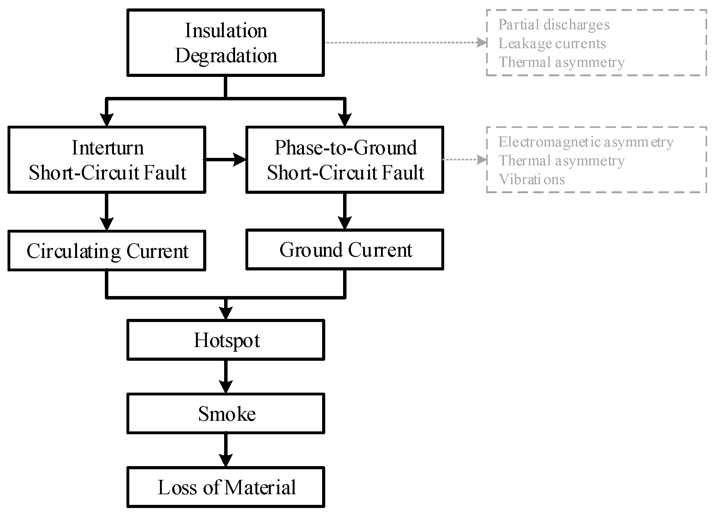
Insulation degradation changes chemical and dielectric characteristics of insulating materials till conductors are no longer insulated, which causes short-circuit faults: interturn faults and ground faults (
Figure 2). An interturn fault due to breakdown of turn insulation leads to circulating currents, excessive heating if rated turn current is exceeded, and further degradation of the insulation. Accordingly, an interturn fault may evolve quickly to a phase-ground fault and result in generator breakdown. Timely short-circuit fault detection aims to prevent local temperature increase, loss of material due to excessively high temperatures (insulation, copper, iron), smoke and potential fire. Symptoms prior to short-circuit fault are difficult to monitor, such as partial discharges, leakage currents, and local temperature increase. Literature most widely addressed signatures appear only after short-circuit fault: electrical and magnetic asymmetry, vibrations, etc. Therefore, the latter ones are in general unsuited for insulation condition monitoring and perhaps of limited value for the wind industry. Fault tolerant generators present themselves as an exception, making use of FD to trigger post-fault operating modes.
The circulating current is an important parameter for the analysis of interturn faults, depending on the fault severity (number of shorted tuns) and location, generator parameters, and operating conditions. Its amplitude is calculated analytically in [
46]. Analysis of inter-turn short-circuit (SC) faults in [
47] shows how the fault/circulating current changes significantly with the number of shorted turns and predicts hotspot temperature by means of electromagnetic-thermal coupled model. One turn shorted is the worst-case scenario with the highest fault current, which decreases as the number of shorted turns increases. The coupling effect—electro-thermal—is found important because the high temperature rise results in the increase of the fault resistance, which reduces predicted fault current and hotspot temperature. The various factors that affect the amplitude of the SC current in PMSMs are investigated in [
48] based on an FEM model, namely load, speed, fault location and branch inductance. Remarks are made with regards to current and voltage harmonics, current differences between parallel branches, and torque ripples (2nd, 4th and 8th harmonics). It is concluded that inductances of the short-circuit turns depend strongly on the fault location (e.g., top versus bottom of the tooth), and a large branch inductance reduces SC current.
Reviews of modeling approaches for interturn faults in PMSMs are found in [
49,
50], which are categorizes as: electrical equivalent circuit based methods (consider machine geometry: winding function theory [
51]), magnetic equivalent circuit based methods (consider geometry, magnetic materials, and winding distribution), and numerical methods (solve Maxwell’s equations: FEM [
52,
53]). FEM are the most accurate and computational demanding. Concerning fault-tolerant PMSMs, analytical models for prediction of inductances and short-circuit current are presented in [
54,
55]. Modeling of surface mounted PMSMs with stator interturn faults is addressed analytically in [
56,
57] in
abc and
dq0 frame. A magnetic equivalent model is proposed in [
58] for high accuracy and real time simulations. An equivalent circuit model in [
59] employs inductance matrices from FE simulations to conclude that interturn fault severity must consider both number of shorted turns and fault resistance.
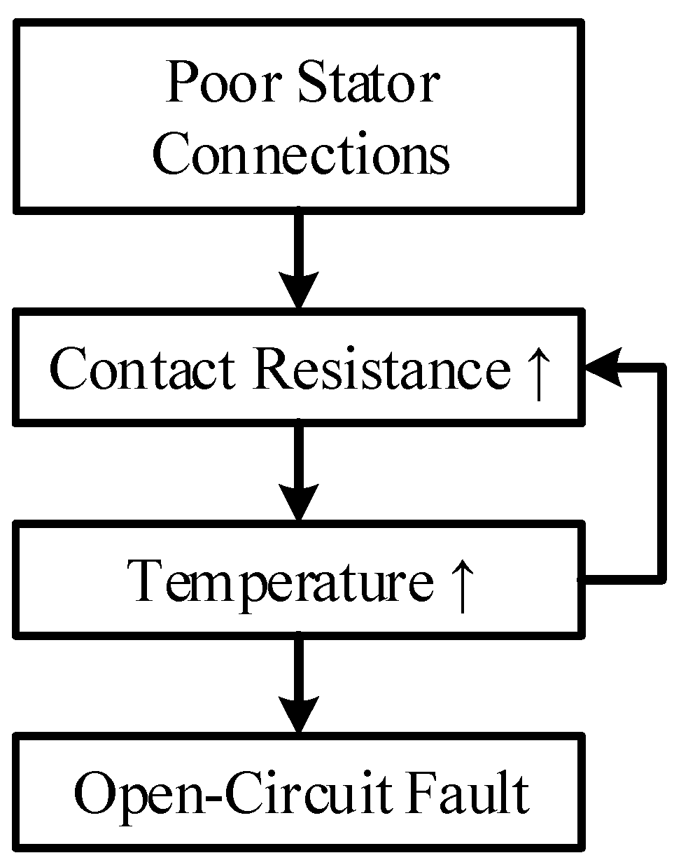
Connection faults also called high resistance or loose connections are found at terminal connections as well as internal generator connections (e.g., parallel branches and/or segments). The connection failure mechanism is illustrated in
Figure 3, often initiated with production errors (e.g., a poorly torqued bolted connection). At the nacelle of a wind turbine, environmental and operating conditions accelerate fault development. In other words, vibration and heat facilitate the increase of contact resistance and connection temperature. Failure causes an open-circuit fault and electrical asymmetry. The debris from burnt insulation and metal may create a conducting path between phases or between phase and ground, thus a short-circuit fault may be detected too. Early detection of connection faults is attempted with visual and physical inspection, PD measurements and thermography. Fault signatures are to some extent the same as for insulation faults, thus similarly challenging to detect at an early stage of fault development. However, fault detection is perhaps good enough in this scenario (e.g., based on electrical asymmetry), provided that a minor connection repair can be carried out on site as opposed to a major repair following insulation failure.
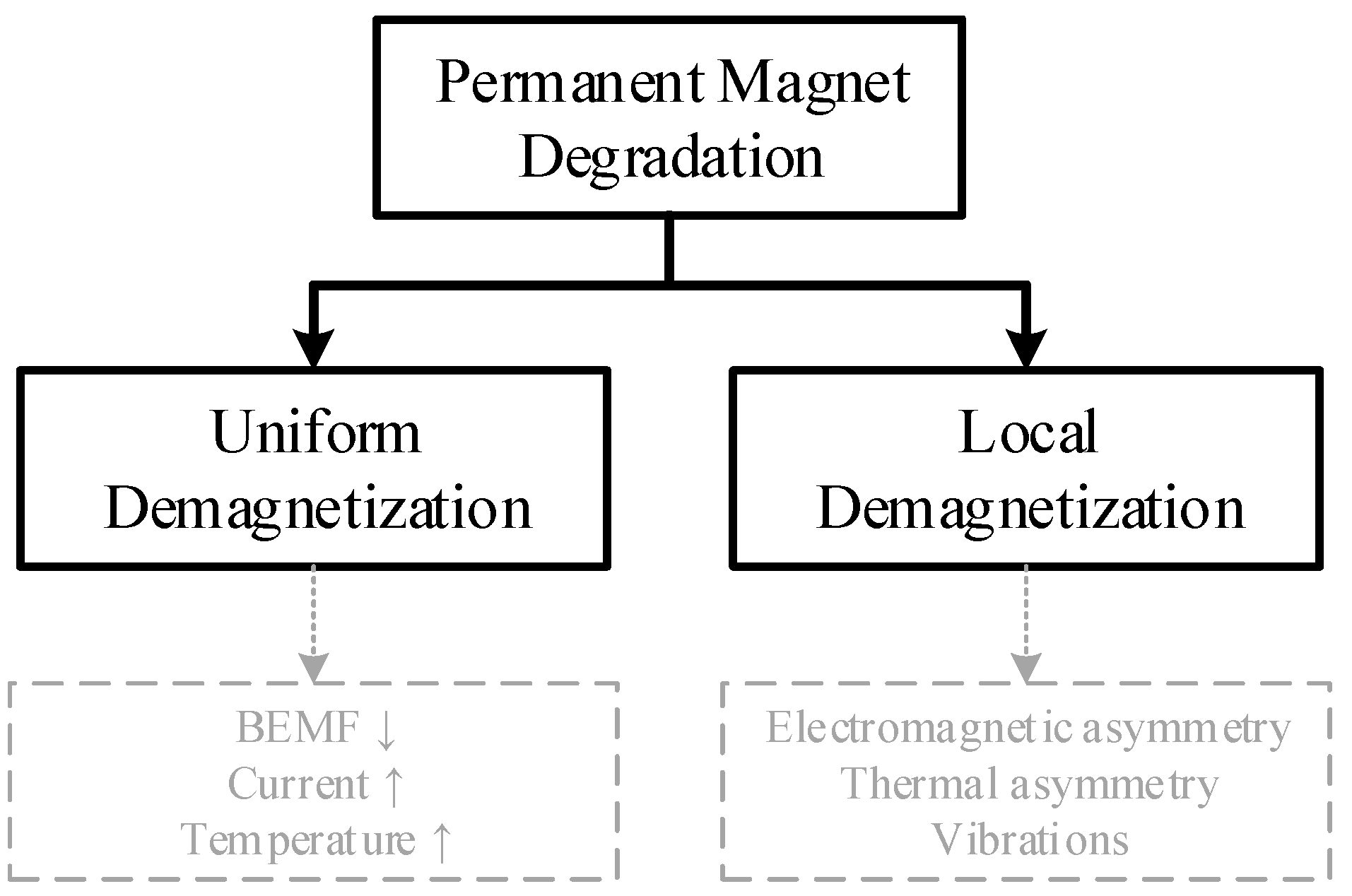
Demagnetization is another important type of faults for PMGs, which failure mechanism is shown in
Figure 4. Having insured high production quality, operational stresses are of extreme importance for the performance of PMGs, since exceeding temperature and current limits can cause irreversible demagnetization. Demagnetization can be partial or uniform, each showing distinct fault signatures due to changes in back-emf harmonics and fundamental amplitude, respectively. The variation of the magnetic saturation of the stator core is the signature exploited in [
60,
61].
6. Offline Testing of PMSGs
Offline methods have been developed for accurate measurements, and their application is twofold: (1) factory testing ensures generators at the end of the production line are fit for purpose; and (2) periodic monitoring assesses health condition throughout the generator design lifetime.
In service offline tests require at least a short outage of the wind turbine, and often require technicians to isolate the machine, install measurement equipment, and carry out the test. This monitoring approach is obviously undesired for offshore WTs. Alternatively, offline testing is done when online monitoring indicates the need for extra data for health assessment, or by equipment permanently installed in the WT for automatic offline testing. This is justified by the fact that degradation symptoms are difficult to measure in real-time during generator operation and remain undetected by conventional protection systems till catastrophic failure.
In addition to the obvious disadvantage that offline tests must be done at discrete times by forcing or waiting for a stop of the WT, offline tests are also carried at operating conditions that differ from normal operation (temperature, vibration, current, etc.), thus under different stress mechanisms that may contribute to erroneous assessment.
Various methods for offline testing are described extensively in [
62]. Many of those are described in IEEE and IEC standards [
63,
64,
65], and a review of IEEE standards for generator winding insulation diagnostic testing is found in [
66]. The petrochemical industry is given as an application example of both offline and online methods for condition monitoring of stator insulation in [
67].
In this section, the most commonly used offline tests for evaluation of stator winding insulation are introduced shortly. On the one hand, concerning testing of ground wall insulation, there are several options: insulation resistance (IR) and polarization index (PI), DC and AC high potential (Hipot) tests, capacitance, dissipation factor, and partial discharges (PD). On the other hand, concerning testing of turn and phase insulation, there are fewer options and the surge test is the only reliable one [
68]. Additionally, poor stator connections may be identified by means of thermal imaging. Examples of offline tests carried out by the converter controller are also included.
6.1. Insulation Resistance and Polarization Index
The first offline test of stator windings to be undertaken is probably always the measurement of insulation resistance (IR), i.e., the resistance between the conductors and the stator core, often known as Megger™ test (popular vendor of measurement instrumentation). The test is performed by applying high voltage between generator winding terminals and stator core (or frame) and measuring current to calculate resistance. High resistance values are expected for a healthy ground wall insulation system able to perform its basic function of blocking current flow between winding and core. The polarization index (PI) test is a variation of the IR test, calculating the ratio of the IR measured for 10 min to the IR measured for 1 min. IR and PI tests can provide the indications of moisture absorption, contamination, or severe damage in the GW insulation.
6.2. DC and AC Hipot Test
In a DC high potential (Hipot) test, DC voltage substantially higher than the rated peak AC voltage is applied at the winding terminals. If the winding fails the test, ground wall insulation has been punctured and repair is mandatory. As Hipot tests can be destructive, they are used as factory test for new windings only. The DC Hipot test does not cause PD nor age the winding insulation. In an AC Hipot test, AC voltage is used, which results in a more uniform voltage distribution and stress across the insulation thickness. Accordingly, major flaws in the ground wall insulation are more likely detectable by AC Hipot.
6.3. Capacitance
Variation of the winding capacitance over time may serve as indicator of several insulation issues, such as thermal ageing, humidity, and contamination. However, the change of capacitance depends strongly on the stress mechanism, potentially increasing or decreasing, which makes the analysis in presence of multiple issues difficult. Capacitance tends to decrease due to thermal ageing because solid insulation delaminates, which is replaced with gas with a lower dielectric constant. Differently, capacitance increases if insulation is saturated by moisture or end windings are contaminated by conductive particles (e.g., dust). Moreover, the stress factor must affect the bulk of the insulation, leaving localized issues undetected. The sensitivity of this test makes it best suited to assess the average condition of the insulation.
6.4. Dissipation Factor
The dissipation factor provides a measure of the insulation dielectric loss, calculated as the tangent of the phase angle between voltage and current measured across the insulation. The phase angle differs from 90 degrees—a pure capacitor—and varies with the change of dielectric loss. Dielectric loss increases with ageing and humidity.
6.5. Offline Partial Discharge
A partial discharge (PD) is a dielectric effect that causes short duration perturbations of generator current and voltage waveforms. PD radiate electromagnetic, optical, acoustic and thermal energy. PD can occur in voids anywhere in the winding insulation, couple capacitively to the coil conductor, and travel to the winding terminals. The PD test enables detection of the biggest defects, where failure is likely to originate. PD testing measures the condition of the worst defect, thus being suitable for detection of local damages.
Offline PD tests measure the pulse currents resulting from PD within a winding energized at rated line-to-ground voltage with high bandwidth transducers (from kHz to MHz). During the test, voltage is increased gradually and the voltage at which the PD is first detected is called the discharge inception voltage (DIV). The voltage is then gradually lowered and the voltage at which the PD is no longer discernible is the discharge extinction voltage (DEV). DIV, DEV and peak PD magnitude are indicators of fault severity.
The most common hardware used for detecting PD is a high voltage capacitor connected to the stator terminals. Other solutions employ high frequency current transformers, Rogowski coils, and antennas. PD does not occur with sinusoidal supply below phase voltages of 3 kV. However, in low voltage inverter-fed generators, short rise-time voltage surges (high dV/dt) can cause PD.
Off-line PD results are not interpreted in isolation, instead they must be compared against other test results used as reference of healthy condition. Such reference may be obtained in several ways: (1) other phases or branches of the same generator; (2) other generators of the same type; (3) trending results over time for one generator. Significant variations over time or between reference and generator under test are indicators of insulation issues.
6.6. Surge Voltage Test
The tests addressed above assess the condition of turn insulation indirectly only when it is part of the groundwall insulation (e.g., form-wound stators), but not the insulation between two adjacent turns. The surge voltage test is the only one that directly determines the condition of the turn insulation. It is analogous to the Hipot tests for ground wall insulation, applying a relatively high voltage surge (short duration and fast rise time pulse) between the turns that punctures a weak enough insulation.
As opposed to detecting a ground fault in a fully assembled generator, detecting interturn SC fault does not trigger overcurrent protections and becomes a non-trivial task. Alternatively, measuring the winding resonant frequency before and after the surge test can show the change in inductance due to interturn fault, but sensitivity is still an issue.
The surge test is a pass/fail test, but it can be combined with offline PD test to provide indication of insulation condition. The surge PD test for CM of turn insulation is addressed in [
69].
6.7. Thermal Imaging
Testing a generator at high current levels and measuring temperature of connections by means of a thermal imaging camera may allow detection of hotspots at connections. However, this test is impractical for generators with complex and non-visible connections, which would require testing at an early stage of the production line to prevent later disassembly. Moreover, the stress imposed in a short duration test may be insufficient to cause a measurable hotspot, and the fault will become evident under normal operation of the WT only.
6.8. Converter Offline Tests
Offline tests can be done regularly at a WT with permanently installed equipment, for which the power converter is the most attractive candidate. Converter control self-commissioning is used to determine system parameters and tune controllers, but it can be extended to detect faults at standstill. Interturn and eccentricity faults are detected by estimating phase impedances with signal injection when at standstill in [
70]. Similar concepts were explored previously, examples are the estimation of
d-axis inductance through a converter start-up routine for detection of airgap eccentricity [
71] and demagnetization [
60,
61]. It is worth noting that the explored concepts are related to magnetic saturation and saliency—also for rotor position estimation with high-frequency signal injection—thus opportunities for integration may exist at a low cost. A method based on estimation of incremental inductance is proposed for detection of static eccentricity in rotational tests at the end of the production line in [
72].
Another offline test suitable for DD generators is the back-emf measurement for condition monitoring of permanent magnets [
73], if voltage sensors are fitted. As opposed to other applications, this test is well suited for WTs because blade pitch control allows the WT to regulate its rotational speed even though the generator is disconnected.
7. Online Fault Detection for PMSGs
Online FD makes use of instrumentation that is permanently installed in a WT to measure relevant quantities continuously. This section addresses electromagnetic measurements such as magnetic flux density, current, voltage, and power. Current measurements are widely available for control and protections functions, whereas the availability of others depend strongly on the requirements of the application. Some examples are search coils for airgap or stray flux measurement, voltage sensors for back-emf measurement, and Rogowski coils to capture the high-frequency content in the neutral current. It is worth reminding the reader that this section on online FD is limited to detecting faults, and in most cases the discussed methods are unsuitable for providing health status information. Faults disrupt the internal symmetry of the generator, and the effects are changes to its electromagnetic variables. A large portion of the state-of-the-art addresses the asymmetric/unbalanced condition of an electrical machine for the sake of FD, which ends up being common to various fault types and making fault discrimination difficult to achieve.
A rich literature is available in the field of FD based on electromagnetic signals for electrical drives, and publications cover several electrical machine types and industrial applications. The review carried out in this section does not discriminate between types of machines and application, provided that the contributions are relevant for FD in PMSG drives. To start with, the authors acknowledge the numerous reviews already published concerning fault diagnosis of electrical machines [
49,
74,
75,
76,
77,
78,
79,
80], with special attention being given to interturn faults that remain an open research topic. The limitations of the state-of-the-art are exposed, which concern robustness against false alarms, sensitivity, and fault discrimination. Airgap and stray flux analysis are pointed out as one of the most promising research trends, however their ability to provide earlier and more reliable warnings and enable fault prognostics in MW generators is still to be demonstrated.
Signal processing methods are used to extract characteristics of interest (so-called features) from the monitored variables, such as FFT (fast Fourier transform), time-frequency methods (Hilbert–Huang and wavelet transforms), Park’s vector-based approaches, symmetrical components, multiple reference frame theory, and more.
7.1. Stator Current Signature Analysis
Analysis of stator current has shown to be a viable technique, capable of detecting faults in electrical and mechanical components of a generator. A fault disturbs the rotating magnetic field and introduces a characteristic frequency in the stator current that depends on the type of fault [
81,
82,
83,
84]. Phase current must be measured in at least one phase of the generator, and the signal processed by the preferred method. Some of the characteristic harmonics created in PMG phase currents by stator faults, partial demagnetization, and airgap eccentricity may coincide.
7.2. Unbalanced Current, Voltage, and Power Signals
By taking advantage of the information contained in asymmetric three phase quantities, various methods were proposed and showed advantageous when compared to the stator current signature analysis. The pattern of the current Park’s Vector representation becomes elliptic in the presence of inter-turn short-circuit faults [
85], as opposed to the circular shape under healthy operation. The extended Park’s vector approach (EPVA) relies on the spectral analysis of the current Park’s Vector modulus [
86], with the component at twice the supply frequency associated to a stator asymmetry. As an alternative to the analysis of negative sequence component of the stator current, a method based on the multiple reference frame theory was proposed in [
87]. In the
dq frame, 2nd order harmonic components can be used for interturn SC fault detection [
88]. Alternative and simple mathematical manipulation of phase currents’ amplitude is proposed in [
89].
The voltage signature analysis is many times similar to the current signature analysis with the requirement to either measure voltages or access voltage references of the power converter. Drawbacks are the need for extra sensors and adequate filtering for measured signals, or errors in reference signals. Synchronous demodulation is used to extract the magnitude of the second harmonic of the
dq voltage references in [
90], allowing interturn fault detection. Diagnostic signals for SC faults are derived from positive and negative sequences of voltage references in [
91]. Measured voltage signals are processed based on the symmetrical component theory in [
92]. The analysis of
dq-axes voltage references is used in [
93] to detect and classify three fault types: eccentricity, demagnetization and interturn SC fault. Amplitude and initial phase angles of zero sequence voltage components (ZSVC) are analyzed in [
94]. Approaches based on ZSVC tend to require access to the generator neutral point. A method based on the 1st harmonic of ZSVC showed improved performance when compared to the 3rd harmonic of the stator currents in [
95]. For detection of low severity interturn faults in [
96], zero-sequence voltages are derived from the converter PWM pattern, and a method based on vector decomposition was proposed.
Instantaneous active and reactive power signature analysis appears as a promising approach that combines information contained in both current and voltage signals. The 2nd harmonic in instantaneous power signals is used for detection of short-circuit and open-circuit fault detection [
97], and high resistance connections [
98]. The instantaneous active power is preferred for interturn fault detection in PMSGs [
99], and the diagnostic signals of multiple three-phase sets can be compared against each other to reduce operating point dependence and improve immunity against transients.
Closed-loop control algorithms implemented in the converter controller impact many of the proposed diagnostic signals. The 2nd harmonic in
q-axis current was found dependent on the gains of field-oriented control in [
100]. Concerning DTC, third harmonic in supply currents is observed in [
101] for both residual stator asymmetry and interturn faults, thus the authors suggest using the multiple reference frames technique. Recent publications address model predictive control (MPC) in the presence of interturn faults and show that signatures are affected by control parameter variations [
102]. The instantaneous reactive power dependence on the current controller bandwidth is tackled in [
103] by an alternative diagnostic signal derived as a weighted average of voltages and currents. The current controllers’ effects concerning demagnetization detection by the stator current signature is presented in [
104]. In conclusion, FD methods must be evaluated together with the closed-loop control system because signatures and fault detection thresholds are expected to depend on chosen control strategies and parameters. Accordingly, distinguishing between generator faults and faults in control or converter hardware turns out to a be challenging task that industrial applications must deal with.
Moreover, temperature and manufacturing tolerances can affect negatively the capabilities of FD methods [
29,
34]. The resulting variations of the values assumed by the diagnostic signals may force to increase thresholds and prevent detection of low severity faults. Alternatively, the complexity of the algorithms is required to increase to compensate the considered effects.
High-resistance electrical connections are many times addressed by the same techniques as interturn faults. Negative-sequence current and zero-sequence voltage are both deemed suitable for detection of high-resistance connections [
105], and their phase is used for discriminating between these high-resistance connections and interturn faults in [
106]. The control strategy is modified to include current controllers in multiple reference frames, whose outputs provide the fault signatures in [
107,
108,
109].
7.3. Model-Based Approaches
Model-based strategies have also been adopted for interturn fault detection. An open-loop physics-based estimator enables the comparison between estimated and reference back-EMF in [
110], and the difference is used for detecting interturn faults. An observer estimates currents, which are compared against measured currents to generate a residual vector in [
111]. Negative-sequence voltage components are calculated by means of a machine model in [
112]. A high-fidelity FE-based model of the healthy machine is deployed to generate current residuals in [
113]. Temperature estimation of electrical machines has been an active research topic for decades, with many publications addressing sensorless estimation of average stator and rotor temperatures. It can be achieved by means of estimation of temperature dependent machine parameters—stator resistance and PM flux. The error between distinct temperature estimates provided by thermal and electrical models is used for condition monitoring in [
114]. Rotor temperature estimation for PMSMs based on measured currents and voltages is addressed in [
115].
7.4. Signal Injection
Current or voltage signal injection by the power converter under operation has been suggested for fault detection. Even though operation and efficiency of the drive are disturbed, fault signatures are less dependent on operating conditions. DC-signal injection was used for detection of high-resistance connection in [
116,
117]. High frequency signal injection was used for detection of interturn faults in [
118]. As an alternative to the injection of an additional HF signal, the current ripple due to PWM is exploited in [
119]. The discrimination between high-resistance connections and interturn faults was addressed by means of multiple HF signals in [
120], and by analyzing the symmetry of HF currents in [
121].
7.5. Flux Monitoring
Flux monitoring concerns airgap and stray flux measurements. Airgap flux measurements require sensor installation inside the machine, which is considered a proven technology in some industries [
122]. Search coils [
123] and FBG magnetostrictive sensors [
124] have been proposed for PM machines. Design, installation, and maintenance of such devices is challenging and avoided by WT manufacturers in serial produced generators.
Stray flux measurements are non-invasive with sensors installed externally to the machine. Therefore, recent research on flux monitoring focus on stray flux due to ease of sensors’ installation in the frame of the machine. These academic publications addressed small size machines, but never large generators. Although there is an increasing number of publications pursuing advances in this field, the present technology readiness level is low, which is evident in the lack of reported field test results.
Axial and radial external magnetic fields are studied under the underlying principle that asymmetries introduced by faults in the airgap and/or end winding magnetic fields are measurable externally to the machine. Even though signals are attenuated by the stator core and frame, it has been claimed that spectral analysis of external magnetic fields is more sensitive than stator current analysis [
76]. Most used sensors are search coils and HE sensors, varying in location and number. Additionally, modeling and computing external magnetic fields is a non-trivial task that requires complex FE models.
Two external flux sensors are placed in the vicinity of the machine and positioned 180° apart from each other in a circumference centered with the machine axis in [
125,
126]. The variations of the amplitude of the spectral components of the two signals enabled detection of interturn SC faults. The 3rd harmonic of stray flux is proposed in [
127], and fault location possible by means of multiple sensors. Three sensors spatially displaced by 120 electrical degrees are installed in the machine’s frame in [
128], and a method based on the Park’s flux vector shows superior sensitivity when compared to other techniques for detection of low severity interturn faults.
7.6. Innovative Approaches
A few examples of innovative approaches are also found in the literature. Arc fault detection based on the current waveform in [
129]. An optical fiber sensor installed in the stator core for strain and temperature measurements to identify faults in bearing elements [
130]. Early detection of interturn short-circuit fault by a fiber Bragg grating (FBG) sensor in situ to monitor winding internal thermal excitation is suggested in [
131], enabling single turn–turn fault detection and fault location. An array of discrete infra-red sensors mounted along the inner wall of the stators’ casing is proposed in [
132] for online monitoring of end windings, enabling detection of hotspots due to interturn SC faults. The number of required sensors was 16 for a 1.5 kW motor, which could increase drastically for a large diameter MW generator. An additional array of hall-effect sensors is presented in [
133] and claimed to be advantageous.
8. Condition Monitoring of PMSGs
The ultimate goal of condition monitoring of generators is to predict the time of failure, enabling condition-based maintenance.
Fault prognosis, as opposed to diagnosis, is a process to predict the evolution of an undesirable condition (fault) till failure—when the generator no longer operates as desired. The predicted time to failure is often called estimated remaining useful life (RUL), which is obtained by means of models. The prediction is only useful if accurate in a short confidence interval, allowing service teams to initiate maintenance activities timely and prevent downtime. Prognosis is based on trending over time a sequence of measurements that depend on the condition of the component being monitored. In other words, the selected features must vary as per the evolution of the fault. Initial lifetime assessment is performed at the design stage with aid of physics-based models that relate to known degradation processes. RUL estimation in service is performed with data-driven models, physics-based models, or a combination of both.
Understanding that detecting a fault and warning the service team minutes in advance of catastrophic failure does not fall within useful fault prognostics. This section addresses methods that can observe slow evolving manifestations of generator winding insulation faults, ideally providing valuable information to service teams for planning maintenance weeks in advance.
In this context, online PD detection has been in the spotlight of academia and industry for long years [
62]. On-line partial discharge testing is claimed to find loose, overheated, and contaminated windings well before these problems lead to failure [
134]. It is widely used in some applications [
135], but not in the wind industry.
On-line PD detection is very similar to the previously described offline PD test. The main differences are that the noise becomes a more prominent issue, and the frequency range of interest increases (e.g., 30–300 MHz). Sensors are capacitors on the generator terminals, antennas, and high-frequency current transformers.
Signal processing to discriminate PD signals from electrical noise is of paramount importance to eliminate pulses originated somewhere else (power lines, inverters, etc.). The increasing PWM frequencies with silicon carbide devices worsen the issue of noise separation. The relative time of arrival and the shape of the pulse are characteristics analyzed often.
PD data under comparison must have been logged under similar operating conditions, because PD activity depends on factors such as stator voltage and current, humidity, and winding temperature. It is worth noting that new windings tend to produce higher PD activity, thus the first few months of data may be of limited use for CM, unless infant mortality becomes obvious in PD indicators. Other observations made are that PD indicators tend to level off after significant degradation took place, but they may plummet when failure is imminent. Historical and present issues with online PD are discussed in [
135]. In short, early start of PD activity and slow progress are very desired characteristics for fault prognostics. However, predicting accurately time to failure is still difficult. Machine learning methods for CM based on PD detection are reviewed in [
136].
Online monitoring of winding insulation capacitance and dissipation factor by measuring the differential leakage-current for each phase was introduced in [
137,
138]. The measurement of the current through the insulation requires a high sensitivity current transformer (HSCT) to be placed around the combined high voltage and neutral leads of a wye-connected stator winding. This technique determines the average condition of the winding insulation, for instance, thermal ageing causes the capacitance to decrease over time. Test results during accelerated life testing are presented in [
139]. The use of a single HSCT to measure common mode insulation leakage current was first proposed in [
140], and further investigated in accelerated life tests [
141] and in the presence of humidity [
142]. The development of the measurement equipment was also presented in [
143,
144]. The estimation of the insulation RUL was proved feasible under thermal ageing in [
141] by calculating an equivalent capacitance value from harmonics of the PWM frequency. The issue of monitoring groundwall and phase-to-phase separately is studied in [
145].
9. Experience with Stator Winding Failure
Several industry surveys have helped to identify the most prone to fail components in electrical machines. Statistics given by these have been used as the motivations for hundreds of research papers. Recently, the experience of Korea Electric Power Corporation Research Institute with stator insulation testing and failures in the power generation industry was discussed in [
68], together with a critical review of existing methods for condition monitoring of turn insulation. Such studies are rarely this thorough, thus some of the valuable insights provided are summarized next. The implementation of periodic offline testing and condition-based maintenance contributed to significantly reduce failures due to stator groundwall (GW) insulation breakdown. Accordingly, most of the recent failures were caused by turn or phase insulation breakdown due to lack of suitable testing methods. Most of the turn insulation failures have been observed to occur in the terminal end of the stator—the end-winding near the slot exit—and attributed to high voltage stress. End-winding turn insulation is likely more vulnerable to failure due to manufacturing processes, vibration, and thermal expansion. Interturn faults at the end-windings can occur and remain undetected without causing GW insulation failure. The lack of acceptance of online interturn FD by the industry is attributed to its limited value, which is to reduce the extent of the damage after a short-circuit fault occurs. It is also stressed that undetected turn faults did not cause stator core damages. Finally, it is concluded that research of new methods for turn insulation condition monitoring and their validation are needed.
Concerning the authors’ experience with DD PMGs for offshore WTs, the fact that existing fleets are young and located remotely results in the available information about generator stator testing and failures being less insightful. High availability levels of DD turbines—between 97% and 99%—align with a very low number of winding insulation failures. To the authors’ knowledge, the limited number of failures tend to occur in the first months of operation due to insufficiently tightened stator connections or foreign objects in airgap and end-windings. These issues were neither detected by factory offline testing of winding insulation nor by rotational tests at the end of the production line. Periodic offline testing is unpractical and such a data base does not exist for offshore generators. Accordingly, the observations discussed next are found most valuable for the sake of online FD.
End-winding interturn SC fault can remain undetected by ground fault protection till smoke is detected. In other words, an interturn insulation failure does not inevitably evolve quickly to a groundwall insulation failure. As opposed to the remarks in [
68], resuming operation of a faulty generator caused damages to increase significantly, thus exposing that there is value in online FD of interturn faults. Despite recognizing its value, the acceptance of state-of-the-art methods like the ones based on electromagnetic asymmetry has been low due to their shortfalls. The challenges with the deployment of such methods were addressed throughout this paper, and again stressed here based on WT fleet data. Fault signatures have shown to vary little with low severity faults, and depend on operating conditions (current, speed, temperature), generator manufacturing tolerances, and abnormal behaviors of converter hardware or software. In summary, there is the need for methods that are more robust, more sensitive, capable of discriminating fault types, and seamless integrated with the converter control system.
High-resistance connections appear to worsen quickly under operation due to thermal expansion and vibrations. As opposed to interturn fault detection, asymmetry-based methods appear to be fit for detection of high-resistance connections. Available data has shown that a fault can evolve to an open-circuit fault in a time window of a few seconds, contradicting usual descriptions of a slow fault development process.
Experience has showed that standard vibration monitoring systems are unsuited for early detection of electrical faults. However, it is worth stressing that fault signatures do exist in vibration signals, which can provide opportunities for improving fault detection in WTs.
10. Fault-Tolerant PMSGs
Fault-tolerant (FT) systems can add high business value when only fault detection is possible. A fault-tolerant generator can continue operation under given conditions after a fault occurrence, preventing a long and costly downtime. The so-called fault-tolerant operation may be achieved automatically by the controller, or only manually after on-site intervention by technicians.
Possibilities for post-fault operation depend strongly on the generator design and the fault itself (type, location, severity level) when concerning interturn SC faults. Reviews of FT PM machines are found in [
146,
147]. Multi-phase fractional slot concentrated winding machines together with FT control [
146], and modified winding configurations to limit the interturn SC current [
55] are suggested. Machine topologies able to tolerate interturn SC faults tend to inherit lower efficiency and power density (large inductance and low power factor). The conflict between efficiency, power density and fault-tolerant capability requirements during the design process is illustrated in [
148]. Therefore, fault-tolerant generators may offer little advantage when compared to other design choices for achieving high reliability like insulation thickness, cooling, and rated operating temperatures.
The control system may attempt to extend the generator lifetime by constraining operating conditions and reducing fault current—perhaps possible at early stage of fault development. The study in [
46] suggests limiting the operating speed, restricting torque, and starting field-weakening to enable post-fault operation.
Another possible approach for enabling post-fault operation after an insulation failure is to cut and bypassed faulty coils—adopted for hydro generator in [
149]. Such remedial action aims to reduce downtime, enabling de-rated operation before a full repair is possible. It is worth noting that the applicability of this solution depends on the generator design and fault type, for instance, it may address end-winding insulation failures.
Regarding high-resistance connections, multiphase generators offer the possibility to operate with the healthy phases only provided that the power output is reduced. Taking a dual three-phase generator as an example, the faulty three-phase system is disconnected, whereas the healthy one keeps running. The described FT drive is often designed to provide continuous operation in the presence of power converter faults.
11. Conclusions and Research Challenges
Condition monitoring (CM) has been proved profitable for the wind industry. Analysis of vibrations and oil are widely used for CM of wind turbines concerning mechanical components such as gearboxes and bearings, detecting faults months before failure. On the other hand, analysis of electrical/electromagnetic quantities suggested for a more cost-effective CM tend to fail detecting faults reliably and early enough, thus have received little acceptance by the industry. Accordingly, some generator fault types can remain undetected till catastrophic failure, meaning that unscheduled stops and downtime are unavoidable. Ultimately, availability and O&M costs of DD wind turbines can be compromised by immature CM methods for PMSGs that either leave faults undetected or generate false alarms.
The analysis of PMSG fault types (stator winding insulation and connection faults, airgap eccentricity, and demagnetization) has showed that various features can be extracted from electromagnetic measurements—current, voltage, power, and flux.
Online FD and CM methods measure these signals continuously during normal operation of a generator. Offline methods are often more accurate but require turbine outage. Therefore, offline tests are better suited for factory tests, onsite fault troubleshooting, and converter self-commissioning procedures at standstill.
Winding insulation failures force immediate stop and unplanned corrective maintenance. Despite the criticality of winding insulation, technologies for its online condition monitoring are found at low readiness levels, thus they have not been deployed fleet wide. In general, online FD methods are unsuitable for providing health status information, instead they aid minimizing damages and triggering fault-tolerant operation.
Experience from other industries has proved periodic offline testing advantageous and mature for groundwall insulation monitoring only, whereas interturn faults tend to remain undetected. The online methods required by the offshore wind industry are generally less advantageous due to their shortfalls, namely robustness, sensitivity to low severity faults, and ability to discriminate fault types.
In the past, many publications in the field of rotating machines addressed fault detection and condition monitoring together, erroneously overstating the capabilities of new proposals. The more recent literature has exposed the limitations of the state-of-the-art in CM of generators to justify the lack of adoption by the industry and motivate new developments.
Trends identified in recently published work are: (1) flux monitoring for fault detection; (2) online capacitance measurement for condition monitoring and estimation of RUL; (3) bulk temperature measurements close to stator windings; (4) development of innovative sensors; and (5) deployment of machine learning and model-based diagnostics. Opportunities for progress may be offered also by incremental improvements in existing technologies. Integration of CM systems with turbine and power converter controllers may improve capabilities at low cost, enabling multi-parameter monitoring and sensor fusion (e.g., vibration and electrical signals). Online PD detection is an old candidate, whose feasibility needs to be demonstrated in wind turbine applications.
To fulfil industry’s demand for CM of PMSGs winding insulation, foreseen research challenges are the development of new sensors and methods tailored to large size PMSGs in wind turbines, and the validation of techniques under laboratory accelerated life tests and in the field.


