Investigation of the Mechanical Properties of a Carbon Fibre-Reinforced Nylon Filament for 3D Printing


Abstract
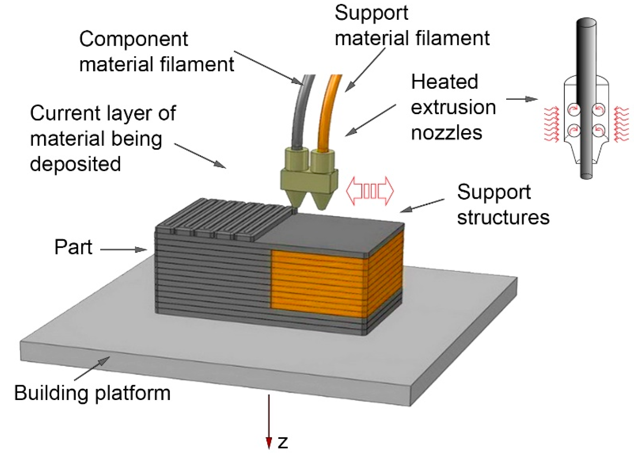
1. Introduction
2. Materials and Methods
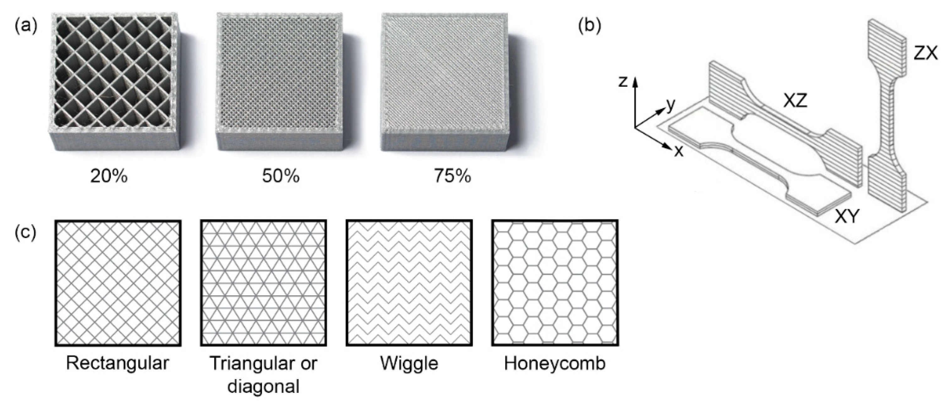
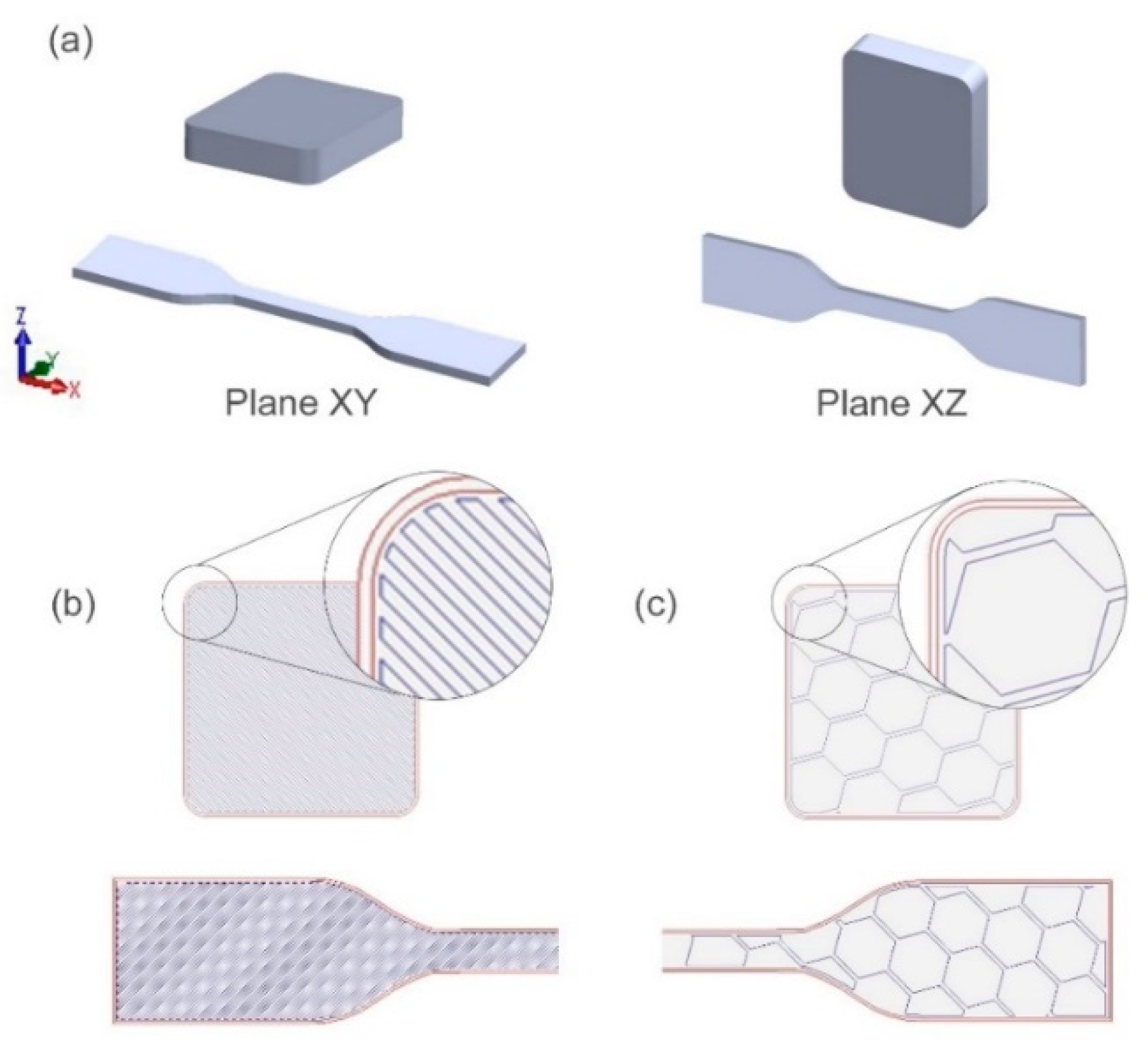
2.1. Fabrication of Samples
2.2. Mechanical Testing
3. Results and Discussion
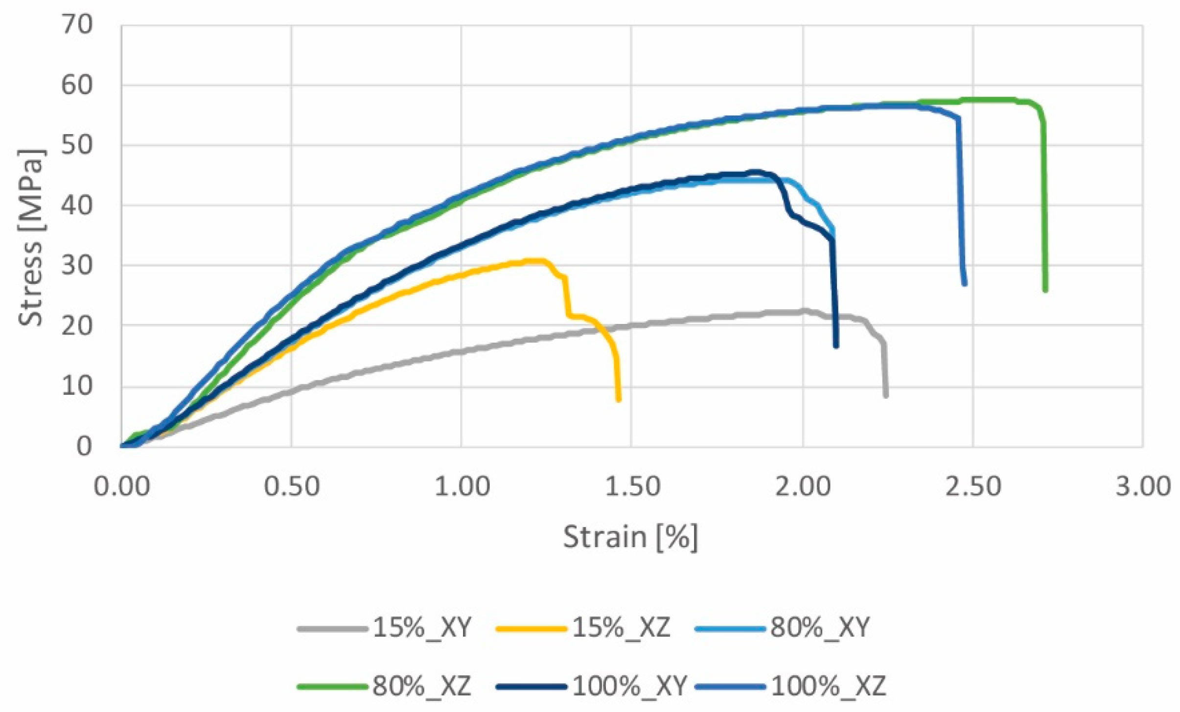
3.1. Hardness and Tensile Properties
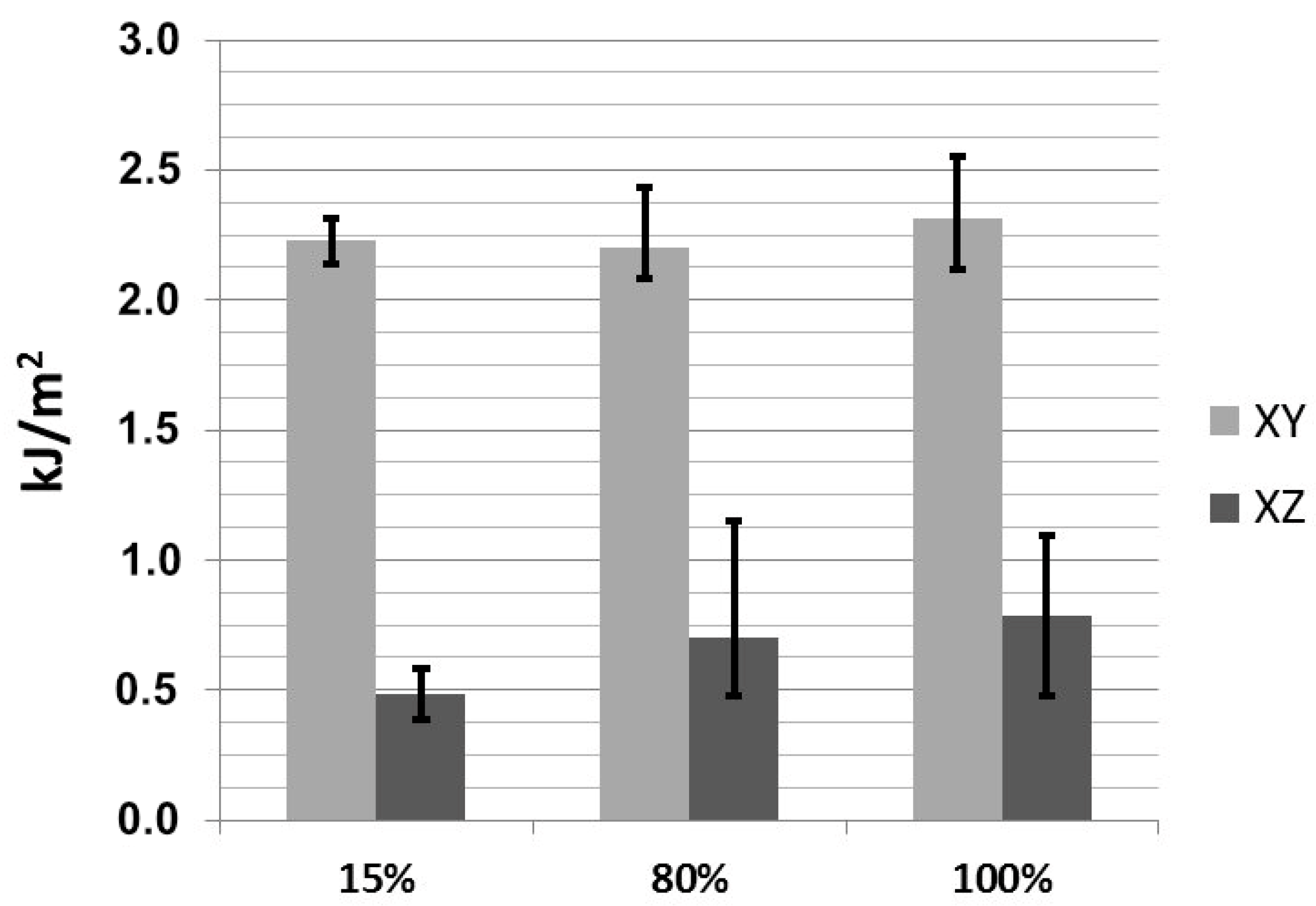
3.2. Resilience
4. Conclusions
- ◦
- The samples produced in the XY plane have higher hardness than the samples built in the XZ plane. The samples built in the XZ plane with 80% and 100% filling have similar hardness values. At a filling percentage of 100%, the samples built in the XZ plane exhibit much lower hardness than those constructed in the XY plane.
- ◦
- The specimens built in the XZ direction are stiffer than those built in the XY direction, in which the former exhibits higher Young’s modulus and higher stress at break. In contrast, the energy at break is higher for the samples built in the XY direction. Furthermore, the relationship between the mechanical properties and filling factor is not linear.
- ◦
- The ISO 527-1/-2 and ASTM D638 standards, although technically equivalent, do not provide fully comparable results
- ◦
- The filling factor does not have a strong influence on the resilience on the XY plane.
Author Contributions
Funding
Acknowledgments
Conflicts of Interest
References
- Kostakis, V.; Niaros, V.; Giotitsas, C. Open source 3D printing as a means of learning: An educational experiment in two high schools in Greece. Telemat. Inform. 2015, 32, 118–128. [Google Scholar] [CrossRef]
- Rayna, T.; Striukova, L.; Darlington, J. Co-creation and user innovation: The role of online 3D printing platforms. J. Eng. Technol. Manag. 2015, 37, 90–102. [Google Scholar] [CrossRef]
- West, J.; Kuk, G. The complementarity of openness: How MakerBot leveraged Thingiverse in 3D printing. Technol. Forecast. Soc. Change 2016, 102, 169–181. [Google Scholar] [CrossRef]
- Boschetto, A.; Bottini, L. Design for manufacturing of surfaces to improve accuracy in Fused Deposition Modeling. Robot. Comput. Integr. Manuf. 2016, 37, 103–114. [Google Scholar] [CrossRef]
- Yang, S.; Tang, Y.; Zhao, Y.F. A new part consolidation method to embrace the design freedom of additive manufacturing. J. Manuf. Process. 2015, 20, 444–449. [Google Scholar] [CrossRef]
- Domingo-Espin, M.; Puigoriol-Forcada, J.M.; Garcia-Granada, A.A.; Llumà, J.; Borros, S.; Reyes, G. Mechanical property characterization and simulation of fused deposition modeling Polycarbonate parts. Mater. Des. 2015, 83, 670–677. [Google Scholar] [CrossRef]
- Baumers, M.; Dickens, P.; Tuck, C.; Hague, R. The cost of additive manufacturing: Machine productivity, economies of scale and technology-push. Technol. Forecast. Soc. Change 2016, 102, 193–201. [Google Scholar] [CrossRef]
- Kroll, E.; Artzi, D. Enhancing aerospace engineering students’ learning with 3D printing wind-tunnel models. Rapid Prototyp. J. 2011, 17, 393–402. [Google Scholar] [CrossRef]
- Wong, K.V.; Hernandez, A. A Review of Additive Manufacturing. ISRN Mech. Eng. 2012, 2019, 7–31. [Google Scholar] [CrossRef]
- Short, D.B. Use of 3D printing by museums: Educational exhibits, artifact education, and artifact restoration. 3D Print. Addit. Manuf. 2015, 2, 209–215. [Google Scholar] [CrossRef]
- Walters, P.; Davies, K. 3D Printing for Artists: Research and Creative Practice. Rapport 2010, 1, 12–15. [Google Scholar]
- Murphy, S.V.; Atala, A. 3D bioprinting of tissues and organs. Nat. Biotechnol. 2014, 32, 773–785. [Google Scholar] [CrossRef] [PubMed]
- Chen, H.; Yang, X.; Chen, L.; Wang, Y.; Sun, Y. Application of FDM three-dimensional printing technology in the digital manufacture of custom edentulous mandible trays. Sci. Rep. 2016, 6, 19207. [Google Scholar] [CrossRef] [PubMed]
- Wang, X.; Jiang, M.; Zhou, Z.; Gou, J.; Hui, D. 3D printing of polymer matrix composites: A review and prospective. Compos. Part B Eng. 2017, 110, 442–458. [Google Scholar] [CrossRef]
- Mohammadizadeh, M.; Fidan, I.; Allen, M.; Imeri, A. Creep behavior analysis of additively manufactured fiber-reinforced components. Int. J. Adv. Manuf. Technol. 2018, 99, 1225–1234. [Google Scholar] [CrossRef]
- Mohan, N.; Senthil, P.; Vinodh, S.; Jayanth, N. A review on composite materials and process parameters optimisation for the fused deposition modelling process. Virtual Phys. Prototyp. 2017, 12, 47–59. [Google Scholar] [CrossRef]
- Sood, A.K.; Ohdar, R.K.; Mahapatra, S.S. Parametric appraisal of mechanical property of fused deposition modelling processed parts. Mater. Des. 2010, 31, 287–295. [Google Scholar] [CrossRef]
- Bagsik, A.; Schöppner, V.; Klemp, E. FDM Part Quality Manufactured with Ultem*9085. In Proceedings of the 14th International Scientific Conference on Polymeric Materials, Halle, Germany, 15–17 September 2010; N.M.Emanuel Institute of Biochemical Physics, Russian Academy of Sciences: Moscow, Russia, 2010. [Google Scholar]
- Torrado Perez, A.R.; Roberson, D.A.; Wicker, R.B. Fracture surface analysis of 3D-printed tensile specimens of novel ABS-based materials. J. Fail. Anal. Prev. 2014, 14, 343–353. [Google Scholar] [CrossRef]
- Ziemian, C.; Sharma, M.; Ziemian, S. Anisotropic Mechanical Properties of ABS Parts Fabricated by Fused Deposition Modelling. In Mechanical Engineering; Intech Open: London, UK, 2012. [Google Scholar]
- Zaldivar, R.J.; Witkin, D.B.; McLouth, T.; Patel, D.N.; Schmitt, K.; Nokes, J.P. Influence of processing and orientation print effects on the mechanical and thermal behavior of 3D-Printed ULTEM® 9085 Material. Addit. Manuf. 2017, 13, 71–80. [Google Scholar] [CrossRef]
- Mohamed, O.A.; Masood, S.H.; Bhowmik, J.L. Experimental Investigations of Process Parameters Influence on Rheological Behavior and Dynamic Mechanical Properties of FDM Manufactured Parts. Mater. Manuf. Process. 2016, 15, 1983–1994. [Google Scholar] [CrossRef]
- Ahn, S.H.; Montero, M.; Odell, D.; Roundy, S.; Wright, P.K. Anisotropic material properties of fused deposition modeling ABS. Rapid Prototyp. J. 2002, 8, 248–257. [Google Scholar] [CrossRef]
- Wu, W.; Geng, P.; Li, G.; Zhao, D.; Zhang, H.; Zhao, J. Influence of layer thickness and raster angle on the mechanical properties of 3D-printed PEEK and a comparative mechanical study between PEEK and ABS. Materials 2015, 8, 5834–5846. [Google Scholar] [CrossRef] [PubMed]
- Tymrak, B.M.; Kreiger, M.; Pearce, J.M. Mechanical properties of components fabricated with open-source 3-D printers under realistic environmental conditions. Mater. Des. 2014, 58, 242–246. [Google Scholar] [CrossRef]
- Lužanin, O.; Movrin, D.; Plan, M. Effect of Layer Thickness, Deposition Angle, and Infill on Maximum Flexural Force in Fdm-Built Specimens. J. Technol. Plast. 2014, 39, 49–58. [Google Scholar]
- Tekinalp, H.L.; Kunc, V.; Velez-Garcia, G.M.; Duty, C.E.; Love, L.J.; Naskar, A.K.; Blue, C.A.; Ozcan, S. Highly oriented carbon fiber-polymer composites via additive manufacturing. Compos. Sci. Technol. 2014, 105, 144–150. [Google Scholar] [CrossRef]
- Shofner, M.L.; Lozano, K.; Rodríguez-Macías, F.J.; Barrera, E.V. Nanofiber-reinforced polymers prepared by fused deposition modeling. J. Appl. Polym. Sci. 2003, 89, 3081–3090. [Google Scholar] [CrossRef]
- Karsli, N.G.; Aytac, A. Tensile and thermomechanical properties of short carbon fiber reinforced polyamide 6 composites. Compos. Part B Eng. 2013, 51, 270–275. [Google Scholar] [CrossRef]
- Love, L.J.; Kunc, V.; Rios, O.; Duty, C.E.; Elliott, A.M.; Post, B.K.; Smith, R.J.; Blue, C.A. The importance of carbon fiber to polymer additive manufacturing. J. Mater. Res. 2014, 29, 1893. [Google Scholar] [CrossRef]
- Ning, F.; Cong, W.; Qiu, J.; Wei, J.; Wang, S. Additive manufacturing of carbon fiber reinforced thermoplastic composites using fused deposition modeling. Compos. Part B Eng. 2015, 80, 369–378. [Google Scholar] [CrossRef]
- Ivey, M.; Melenka, G.W.; Carey, J.P.; Ayranci, C. Characterizing short-fiber-reinforced composites produced using additive manufacturing. Adv. Manuf. Polym. Compos. Sci. 2017, 3, 81–91. [Google Scholar] [CrossRef]
- Papon, E.A.; Haque, A. Fracture toughness of additively manufactured carbon fiber reinforced composites. Addit. Manuf. 2019, 26, 41–52. [Google Scholar] [CrossRef]
- Rao, V.D.P.; Rajiv, P.; Geethika, V.N. Effect of fused deposition modelling (FDM) process parameters on tensile strength of carbon fibre PLA. Mater. Today Proc. 2019, 18, 2012–2018. [Google Scholar]
- Yasa, E. Anisotropic impact toughness of chopped carbon fiber reinforced nylon fabricated by material-extrusion-based additive manufacturing. Anadolu Univ. J. Sci. Technol. Appl. Sci. Eng. 2019, 20, 195–203. [Google Scholar]
- Der Klift, F.; van Koga, Y.; Todoroki, A.; Ueda, M.; Hirano, Y.; Matsuzaki, R. 3D Printing of Continuous Carbon Fibre Reinforced Thermo-Plastic (CFRTP) Tensile Test Specimens. Open J. Compos. Mater. 2016, 6, 18. [Google Scholar] [CrossRef]
- Melenka, G.W.; Cheung, B.K.O.; Schofield, J.S.; Dawson, M.R.; Carey, J.P. Evaluation and prediction of the tensile properties of continuous fiber-reinforced 3D printed structures. Compos. Struct. 2016, 153, 866–875. [Google Scholar] [CrossRef]
- Dickson, A.N.; Barry, J.N.; McDonnell, K.A.; Dowling, D.P. Fabrication of continuous carbon, glass and Kevlar fibre reinforced polymer composites using additive manufacturing. Addit. Manuf. 2017, 16, 146–152. [Google Scholar] [CrossRef]
- Tian, X.; Liu, T.; Yang, C.; Wang, Q.; Li, D. Interface and performance of 3D printed continuous carbon fiber reinforced PLA composites. Compos. Part A Appl. Sci. Manuf. 2016, 88, 198–205. [Google Scholar] [CrossRef]
- McKeen, L.W. The Effect of Long Term Thermal Exposure on Plastics and Elastomers; William Andrew: Norwich, NY, USA, 2013; ISBN 9780323221085. [Google Scholar]
- Fiber Force Italy. Available online: http://www.fiberforce.it/wp-content/uploads/2019/07/TDS_NY-CARBON_REV-2.1.pdf (accessed on 23 August 2020).
- Akhoundi, B.; Behravesh, A.H. Effect of Filling Pattern on the Tensile and Flexural Mechanical Properties of FDM 3D Printed Products. Exp. Mech. 2019, 59, 883–897. [Google Scholar] [CrossRef]
- ASTM International. ISO/ASTM52900-15 Standard Terminology for Additive Manufacturing—General Principles—Terminology; ASTM International: West Conshohocken, PA, USA, 2015. [Google Scholar]
- Rodríguez, J.F.; Thomas, J.P.; Renaud, J.E. Mechanical behavior of acrylonitrile butadiene styrene fused deposition materials modeling. Rapid Prototyp. J. 2003, 9, 219–230. [Google Scholar] [CrossRef]
- Abeykoon, C.; Sri-Amphorn, P.; Fernando, A. Optimization of fused deposition modeling parameters for improved PLA and ABS 3D printed structures. Int. J. Light. Mater. Manuf. 2020, 3, 284–297. [Google Scholar] [CrossRef]
- Fernandez-Vicente, M.; Calle, W.; Ferrandiz, S.; Conejero, A. Effect of Infill Parameters on Tensile Mechanical Behavior in Desktop 3D Printing. 3D Print. Addit. Manuf. 2016, 3, 183–192. [Google Scholar] [CrossRef]
- Torrado, A.R.; Roberson, D.A. Failure Analysis and Anisotropy Evaluation of 3D-Printed Tensile Test Specimens of Different Geometries and Print Raster Patterns. J. Fail. Anal. Prev. 2016, 16, 154–164. [Google Scholar] [CrossRef]
- Fused Deposition Modelling (FDM) Parts on Demand. Available online: https://www.stratasysdirect.com/materials/fused-deposition-modeling (accessed on 20 September 2001).
- Markforged, Material. Available online: https://markforged.com/materials/composites/ (accessed on 20 August 2020).
- Products-Maker—Fiberforce. Available online: http://www.fiberforce.it/products-maker/ (accessed on 20 August 2020).
- Data Sheets Fillamentum. Available online: https://fillamentum.com/pages/data-sheets (accessed on 22 August 2020).
- García-Domínguez, A.; Claver, J.; Camacho, A.M.; Sebastián, M.A. Considerations on the applicability of test methods for mechanical characterization of materials manufactured by FDM. Materials. 2020, 13, 28. [Google Scholar] [CrossRef] [PubMed]
- Friday, M.J. A comparison of tension test data using ASTM D 638 and ISO 527. In ASTM Limitations of Test Methods for Plastics; ASTM International: West Conshohocken, PA, USA, 1999. [Google Scholar]
- Yasa, E.; Ersoy, K. Dimensional Accuracy and Mechanical Properties of Chopped Carbon Reinforced Polymers Produced by Material Extrusion Additive Manufacturing. Materials 2019, 12, 3885. [Google Scholar] [CrossRef]


| Reinforcement | Matrix Material | Investigated Properties | Limitations | References |
|---|---|---|---|---|
| Carbon fibres | ABS | Tensile strength and tensile modulus | Porosity, weak interfacial adhesion between the fibres and the matrix and fibre breakage | [27] |
| Vapour-grown carbon fibres | ABS | Tensile strength and tensile modulus | Interlayer fusion, intralayer fusion, and a change from ductile to brittle behaviour | [28] |
| Carbon fibres | ABS | Strength, stiffness, thermal properties, distortion, and geometric tolerances | [30] | |
| Carbon fibres | ABS | Tensile strength, Young’s modulus, and flexural properties | Decreases in toughness, yield strength and ductility and increases in porosity with increased carbon fibre content | [31] |
| Carbon fibres | PLA | Tensile strength and tensile modulus | [32] | |
| Carbon fibres | PLA | Fracture properties | Critical factors for the fracture toughness: bead layup sequence, fiber pullout, interfacial de-bonding, and void formation | [33] |
| Carbon fibres | PLA | Tensile strength | Tensile strength increases with infill density and low layer thickness | [34] |
| Carbon fibres | Nylon | Charpy impact testing | Toughness results show a severe anisotropy in toughness and high dependence on the infill strategy | [35] |
| Reinforcement | Matrix Material | Investigated Properties | Limitations | References |
|---|---|---|---|---|
| Carbon fibres | Nylon | Tensile properties | Discontinuities of the fibres and porosity | [36] |
| Carbon, glass and Kevlar fibres | Nylon | Tensile properties | Poor bonding and porosity | [37] |
| Carbon, glass and Kevlar fibres | Nylon | Tensile and flexural properties | Weak bonding and porosity | [38] |
| Carbon fibres | PLA | Flexural strength and modulus | None reported | [39] |
| 3D Printer | Filament | Value |
|---|---|---|
| Sharebot Next Generation | Diameter | 1.75 mm |
| Extruder temperature | 230 °C | |
| Bed temperature | 40 °C | |
| Perimeter print speed | 35 mm/s | |
| Infill and support print speed | 40 mm/s | |
| Layer height | 0.20 mm |
| Number Indentation | Filling Percentage and Building Direction | |||||
|---|---|---|---|---|---|---|
| 15%, XY | 15%, XZ | 80%, XY | 80%, XZ | 100%, XY | 100%, XZ | |
| 1 | 14.4 | 10.1 | 55.6 | 48.5 | 80.1 | 51.1 |
| 2 | 10.3 | 9.2 | 54.7 | 49.3 | 80.9 | 45.4 |
| 3 | 13.0 | 11.5 | 53.5 | 52.2 | 78.3 | 52.2 |
| 4 | 10.3 | 13.0 | 48.2 | 53.7 | 75.3 | 41.3 |
| 5 | 8.5 | 10.0 | 55.9 | 45 | 81.9 | 43.4 |
| Average | 11.3 | 10.8 | 53.6 | 49.7 | 79.3 | 46.7 |
| Std. dev. | 2.4 | 1.5 | 3.1 | 3.4 | 2.6 | 4.8 |
| Sample | Young’s Modulus E [MPa] | σY [MPa] | σUTS [MPa] | σbreak [MPa] | Elongation at Break [%] | Energy at Break [mJ] |
|---|---|---|---|---|---|---|
| 15%, XY | 930 ± 77 | 17 ± 0.3 | 22 ± 0.7 | 21 ± 0.7 | 2.0 ± 0.2 | 202 ± 50 |
| 15%, XZ | 1467 ± 21 | 26 ± 0.8 | 31 ± 0.6 | 25 ± 0.6 | 1.5 ± 0.1 | 76 ± 15 |
| 80%, XY | 1552 ± 60 | 35 ± 0.4 | 44 ± 1.2 | 37 ± 1.2 | 2.2 ± 0.1 | 625 ± 194 |
| 80%, XZ | 2294 ± 154 | 36 ± 1.8 | 57 ± 4.1 | 44 ± 4.1 | 2.6 ± 0.5 | 361 ± 119 |
| 100%, XY | 1625 ± 64 | 39 ± 1.4 | 45 ± 1.9 | 38 ± 1.9 | 2.0 ± 0.1 | 464 ± 209 |
| 100%, XZ | 2403 ± 95 | 42 ± 1.7 | 56 ± 3.9 | 45 ± 3.9 | 2.8 ± 1.0 | 163 ± 89 |
| Manufacturer Data | Young’s Modulus E [MPa] | σy [MPa] | σbreak [MPa] | Elongation at Break [%] | Energy at Break [J] |
|---|---|---|---|---|---|
| Injection moulded – Nylon Carbon | 6000 | 100 | - | - | - |
| Nylon 12CF (Stratasys) | 7515 | 63.4 | 76 | 1.9 | - |
| (100%, XZ) | (100%, XZ) | (100%, XZ) | (100%, XZ) | ||
| Nylon Carbon (Fiber Force) | 1844 | - | 33.7 | 5.7 | 5.45 |
| (15%, XY) | (15%, XY) | (15%, XY) | (15%, XY) | ||
| 2758 | 66.3 | 6.7 | 12.2 | ||
| (100%, XY) | (100%, XY) | (100%, XY) | (100%, XY) | ||
| CF112 (Fillamentum) | 2200 | 52.4 | 37.7 | 8 | - |
| Nylon (Stratasys) | 1282 | 32 | 46 | 3.0 | - |
| (100%, XZ) | (100%, XZ) | (100%, XZ) | (100%, XZ) | ||
| Nylon (Fiber Force) | 881.9 | - | 20.7 | 13.94 | 10.48 |
| (15%, XY) | (15%, XY) | (15%, XY) | (15%, XY) | ||
| 1529.0 | 41.1 | 31.30 | 49.70 | ||
| (100%, XY) | (100%, XY) | (100%, XY) | (100%, XY) | ||
| Nylon (Markforged) | 940 | 54 |
© 2020 by the authors. Licensee MDPI, Basel, Switzerland. This article is an open access article distributed under the terms and conditions of the Creative Commons Attribution (CC BY) license (http://creativecommons.org/licenses/by/4.0/).
Share and Cite
Calignano, F.; Lorusso, M.; Roppolo, I.; Minetola, P. Investigation of the Mechanical Properties of a Carbon Fibre-Reinforced Nylon Filament for 3D Printing. Machines 2020, 8, 52. https://doi.org/10.3390/machines8030052
Calignano F, Lorusso M, Roppolo I, Minetola P. Investigation of the Mechanical Properties of a Carbon Fibre-Reinforced Nylon Filament for 3D Printing. Machines. 2020; 8(3):52. https://doi.org/10.3390/machines8030052
Chicago/Turabian StyleCalignano, Flaviana, Massimo Lorusso, Ignanio Roppolo, and Paolo Minetola. 2020. "Investigation of the Mechanical Properties of a Carbon Fibre-Reinforced Nylon Filament for 3D Printing" Machines 8, no. 3: 52. https://doi.org/10.3390/machines8030052
APA StyleCalignano, F., Lorusso, M., Roppolo, I., & Minetola, P. (2020). Investigation of the Mechanical Properties of a Carbon Fibre-Reinforced Nylon Filament for 3D Printing. Machines, 8(3), 52. https://doi.org/10.3390/machines8030052