Article

Automotive Lightweight Design: Simulation Modeling of Mass-Related Consumption for Electric Vehicles

Department of Industrial Engineering, University of Florence, Via di S. Marta 3, 50139 Florence, Italy
*
Author to whom correspondence should be addressed.
Machines 2020, 8(3), 51; https://doi.org/10.3390/machines8030051
Submission received: 14 August 2020 / Revised: 30 August 2020 / Accepted: 31 August 2020 / Published: 3 September 2020

Abstract

:
A thorough assessment of Life-Cycle effects involved by vehicle lightweighting needs a rigorous evaluation of mass-induced consumption, on which energy and sustainability benefits during use stage directly depend. The paper proposes an analytical calculation procedure to estimate the weight-related energy consumption of pure Electric Vehicles (EVs), since existing literature leaves considerable room for improvement regarding this research area. The correlation between consumption and mass is expressed through the Energy Reduction Value (ERV) coefficient, which quantifies the specific consumption saving achievable through 100 kg mass reduction. The ERV is estimated for a number of heterogeneous case studies derived from real 2019 European market EV models and according to three drive cycles, to consider different driving behaviors. For the case studies under consideration, ERV ranges from 0.47 to 1.17 kWh/(100 km × 100 kg), with the variability mainly depending on vehicle size and driving cycle. Given the high uncertainty of mass-related consumption on car size, an analytical method is refined to estimate accurately the ERV for any real-world EV model, starting from vehicle technical features. Along with energy assessment, the research also evaluates the environmental implications of lightweight design by means of the Impact Reduction Value (IRV), which is estimated for three distinct electricity grid mixes. Finally, the ERV/IRV modeling approach is applied to a series of comparative lightweight case studies taken from the literature. Such an application demonstrates the effective utility of the work to reduce the uncertainty for all cases where no physical tests or computer-aided simulations are available.

1. Introduction

Energy-resources depletion and global climate change represent one of the major concerns for modern societies worldwide [1,2]. The desire for improved energy security and reduced global climate change has led to many industry and research developments to reduce fossil fuel consumption due to human activities [3,4]. The road transportation sector accounts for a relevant quota of total energy demand and air emissions on a global scale [5]. Since operation is the most energy-consuming phase within car’s Life Cycle, strong efforts have been put to improve the fuel economy of light-duty vehicles [6]. The literature provides a series of works that investigate a wide range of possible solutions to achieve this ambitious target, such as the use of alternative fuels, the development of more efficient propulsion technologies, vehicle downsizing, an increase in powertrain efficiency and reduction in vehicle size, aerodynamic drag, or rolling resistance [7,8,9]. Another highly promising way to provide more sustainable mobility is lightweight design. Lightweighting presents a very high potential to decrease use stage consumption, since car mass and energy consumed during operation are strongly correlated: A 10% weight reduction entails a decrease in fuel consumption of about 3–6% at comparable functionality levels [10,11]. In the last decade, automotive lightweighting has been deeply investigated with respect to the most varied options for car mass reduction (redesign of single components/assemblies, use of weight-efficient materials in substitution of conventional ones, and optimization of manufacturing technologies and processes), and the implications of these new design strategies have been evaluated on a Life-Cycle perspective from both an energy and environmental point of view [12,13,14]. In this regard, the literature studies seem rather in agreement in affirming that lightweight materials and innovative manufacturing technologies generally require more energy and generate more greenhouse gas emissions than traditional solutions in the vehicle-cycle (all processes needed for vehicle production) [15,16,17]. On the other hand, mass reduction involves a decrease of consumption during operation which leads to undeniable energy and environmental benefits in the fuel-cycle (all processes related to fuel/energy production and consumption) [18,19,20]. As a result, the possible trade-offs between vehicle-cycle and fuel-cycle stages require an accurate evaluation of weight reduction effects on operation consumption to properly assess the effective profitability of novel design solutions [21,22,23]. Another relevant point is that studies dealing with the assessment of lightweight case studies are affected by different assumptions and methods, the most relevant being the mass-substitution ratio between innovative/conventional materials and the weight-induced fuel consumption [24,25,26]. In particular, the latter plays a key role in the estimation of use stage energy absorption and the chosen approach for the modeling of energy consumption saving can result in notable variations of results on the overall Life-Cycle perspective [27,28]. Typically, fuel saving from lightweighting is estimated through two metrics, that are fuel-mass correlations and fuel reduction values. Fuel-mass correlations express the fuel-mass elasticity in terms of proportional fuel economy change divided by proportional weight decrease (e.g., 7% consumption reduction for 10% weight decrease) [29,30], while Fuel Reduction Values (FRVs) provide the saving in specific consumption achieved through a 100 kg weight saving (e.g., L/(100 km × 100 kg) for an Internal Combustion Engine Vehicle (ICEV) or kWh/(100 km × 100 kg) for a Battery Electric Vehicle) [31]. However, the FRV approach appears more appropriate to measure weight-induced energy consumption, since fuel-mass correlations do not take into account the non-mass related loads (such as auxiliary loads or aerodynamic drag resistance), which differ strongly among different vehicle models. Currently, the problem of estimating use stage weight-induced consumption has been mainly investigated for ICE cars [32]. The studies give a wide range of results with FRV that varies between 0.1 and 0.6 L/(100 km × 100 kg), depending on several modeling assumptions, such as vehicle class, car model, driving cycle, and whether powertrain adjustment is performed for performance equivalence [33,34]. However, some studies provide mathematical models able to derive affordable FRVs for generic car models, starting from powertrain technical features [35,36,37].
Concerning advanced powertrain vehicles (electric, hybrid, and fuel cells), the fuel-mass correlation is dealt with by a limited number of researches [38,39], and the obtained results are compared with the ones of ICEVs [40,41,42]. These studies generally find that the marginal energy savings from lightweighting are lower for advanced technology cars (about 30–50% less than ICEVs) and associate this to the greater powertrain efficiency (and therefore lower consumption) of vehicles with higher reliance on electric motors [43]. The study of Kim and Wallington [44] is the only work that investigates FRVs for different powertrain technologies, including also Battery Electric Vehicles (BEVs): A physics-based calculation method is applied to specific car models of ICEVs, BEVs, hybrid Electric Vehicles, and plug-in hybrid Electric Vehicles based on the US Federal Test Procedure (FTP) combined (55-city/45 highway) driving cycle. The outcomes of the study reveal that FRV varies widely depending on car model features and powertrain type, with BEVs that provide the lowest mass-induced consumption (comprised within the range of 1.3–2.3 L equivalent per 100 km) with respect to the other propulsion technologies, especially ICEVs. The authors conclude that, given the large variability of FRV due to car technical features, general harmonized recommendations for mass-consumption correlation are not available and that a model-specific assessment is required to properly evaluate real-life case studies. The review article of Luk et al. [45] confirms that electric cars offer the lowest energy-saving potential from lightweight design, but it stresses also that lower consumption allows downsizing the battery based on the same driving range, thus providing additional valuable mass reduction that further increases energy saving.
The state-of-the-art shows that while a notable research activity has been carried out on the analysis of mass-consumption correlation for ICEVs, large margins of investigation still remain for advanced powertrain cars. First of all, fuel-mass correlations proposed by several studies do not represent a thorough metric for FRV estimation, since they involve conflating assumptions with respect to non-mass-related loads when comparing different vehicles. Moreover, most of simulation modeling activities are based on theoretical cars, with no indications on car model names and model years. In particular, for BEVs, the literature provides only one study which performs a thorough simulation modeling of the FRV coefficient based on data of specific car models currently in use. However, the paper does not provide guidance on estimating mass-consumption correlation for real-world vehicles, and the large variability of results due to car model makes unreliable the assessment of lightweighting through generic FRVs. Additionally, the calculations are based on the standardized driving cycle effective in the geographical area of the study, with no general relevance on a global scale, and the sustainability implications of mass reduction are not taken into account.
This study presents an analytical calculation procedure for mass-induced energy consumption of pure Electric Vehicles. The target of the work is providing support in the assessment of energy and sustainability implications of lightweighting within the BEV field. The estimation of mass-consumption correlations is based on car model-specific data, in order to minimize the uncertainties of results with respect to the use of hypothetical vehicles data. The simulation modeling is carried out for a number of specific case studies belonging to a wide range of car size and class, thus taking into account a broad range of vehicle technical features. Moreover, the mass-induced consumption is evaluated based on a set of driving cycles, both developed by international standardization and research activities, to capture the effects of different driving patterns. Finally, the research includes the sustainability assessment through the calculation of environmental-impact-reduction values, which are also applied to a series of the literature case studies.

2. Materials and Methods

The analysis of the correlation between vehicle mass and use-stage consumption/environmental impact is carried out in two main calculation sections. The first one estimates the energy absorption for various mass-configurations of a certain number of BEV case studies by a simulation modeling of car system dynamics. The second section evaluates the effects of weight reduction on both use-phase consumption and environmental impact through the correlation between mass and energy absorbed in the different configurations.

2.1. Simulation Modeling of Vehicle Consumption

The calculation of car consumption is carried out through a simulation model developed by the software MATLAB-Simulink [46]. The refined model simulates vehicle longitudinal dynamics, and it falls in the category of “forward models”, according to the literature examples [35,36,47]. The modeling provides the calculation of motor torque required to follow a certain driving cycle by reproducing the operation of all drivetrain components [48]. The model is composed of four main sections (Figure 1): driver, powertrain, driveline, and energy management.
The driver section is based on a speed-follower Proportional–Integral–Derivative (PID) controller. The model includes a look-forward secondary PID for driving cycle acceleration and deceleration anticipation (anticipation factor being 1 s) with derivative part set to zero. The PID controller is functional to appropriately “smooth” simulated driving when adopting rigid cycles that provide suddenly varying acceleration sequences (e.g., the New European Driving Cycle (NEDC), for which acceleration is supposed to pass immediately from zero to constant value). The brake blending controller (Drv control in Figure 1) regulates the brake request from the user, to provide separate torque request from powertrain (regenerative braking torque) and mechanical braking.
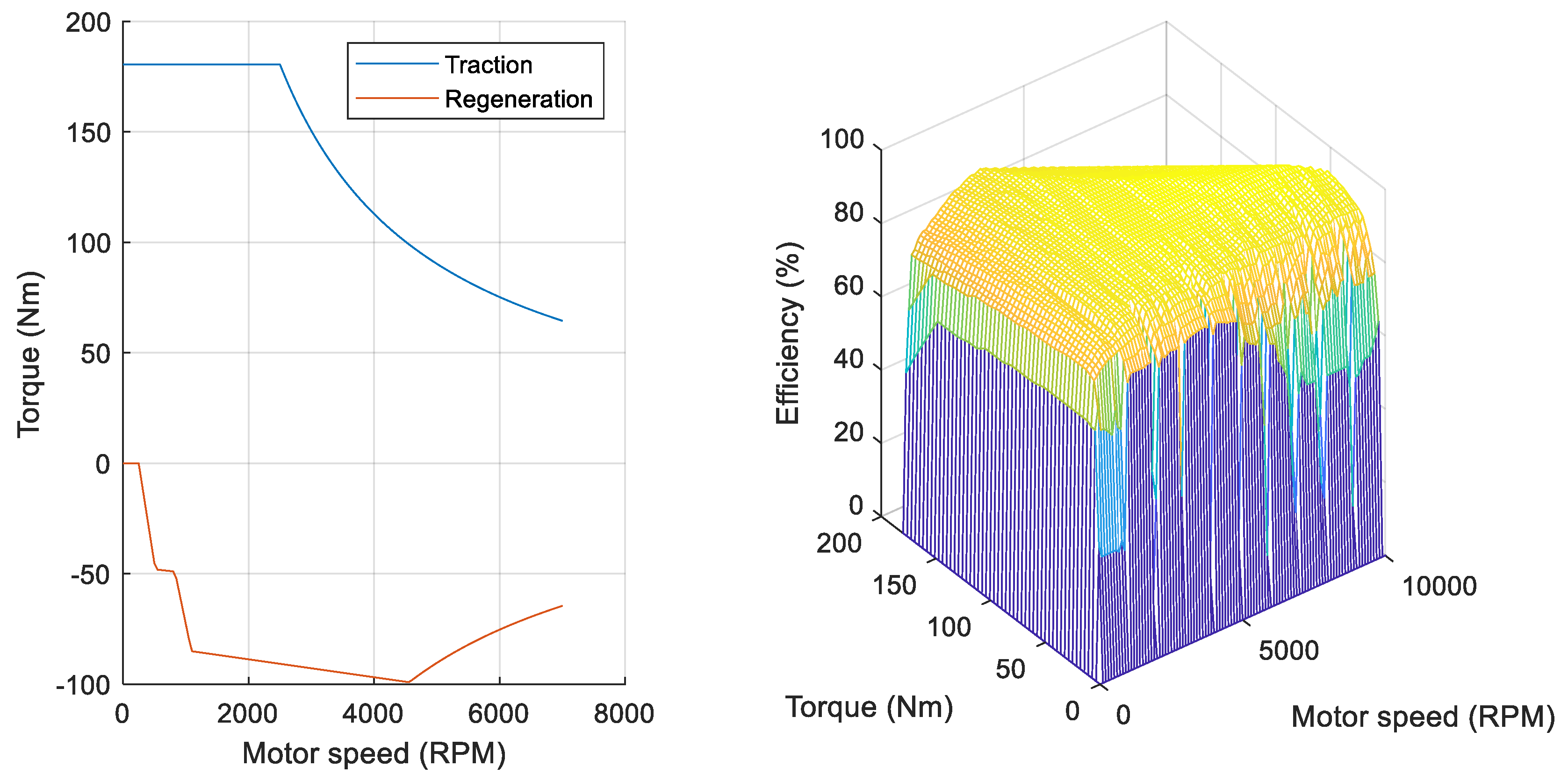
The powertrain section includes the battery and motor sub-models. The battery sub-model (Thevenin-based) is built on the characteristics of Mitsubishi i-MiEV cells (used in a 16 kWh battery pack [49]), and it is adapted to the specific vehicle case study by scaling on the basis of the effective battery capacity. The motor sub-model is based on look-up-tables (Figure 2) functional to define traction torque, regenerative braking torque, and efficiency (combined value considering motor and inverter). Data are coming from automotive Permanent Magnet Synchronous Motor (PMSM) testing [50], and they are rescaled and adapted to vehicle case studies (a typical approach for archetype comparison), on the basis of car model specifications (nominal torque, motor speed, and efficiency).
The driveline section models inertia (evaluated as vehicle mass in running order corrected by a factor representing equivalent inertia of main rotating elements in driveline) and friction characteristics (calculated on the basis of car aerodynamics and tire rolling friction). The section is composed of the following sub-models: braking (providing braking torque to the wheels), wheels (providing longitudinal force from braking and traction force, modified according to rolling friction), car body (modeling longitudinal dynamics including equivalent rotating masses), and auxiliaries (modeling lighting and basic electric and electronics components, average consumption being about 180 W).
The energy management section estimates the electricity consumption, taking into account the regenerative braking. The model is based on a simplified blending criteria between electric and mechanical braking (Figure 3), which is aimed at limiting the regenerative braking torque within the driveline admissible limits (exceeding braking torque, when needed, is provided by the mechanical braking system). The selected approach provides over various driving cycles results comparable to expectations (e.g., regenerated energy over known driving cycles being in the range from 15 to 25%, depending on cycle characteristics [48]). The section is composed of the following sub-models: battery, super-capacitor, and range extender. Super-capacitor and range-extender sub-models are not used for this application, since the energy management provides that power is simply redirected to the battery.
The calculation of energy consumption is performed for 10 BEV case studies belonging to A/B, C, and D/E classes. The choice of a wide spectrum of car size allows us to model the correlation between mass and electricity absorption, taking into account the strong variation of vehicle technical features (mainly mass, motor power, and power-to-weight ratio) that occurs passing from one segment to another. To obtain realistic values of energy consumption, technical features of case studies refer to specific vehicle models from the 2019 EV European market. The choice to use real-life cars is performed in order that the considered case studies are as much as possible representative of the vast majority of BEVs sold in Europe, thus covering all possible intended uses, from entry level to high-performance/luxury segments. Table A1 in Appendix A reports the technical features of vehicle models taken into account in the simulation modeling.
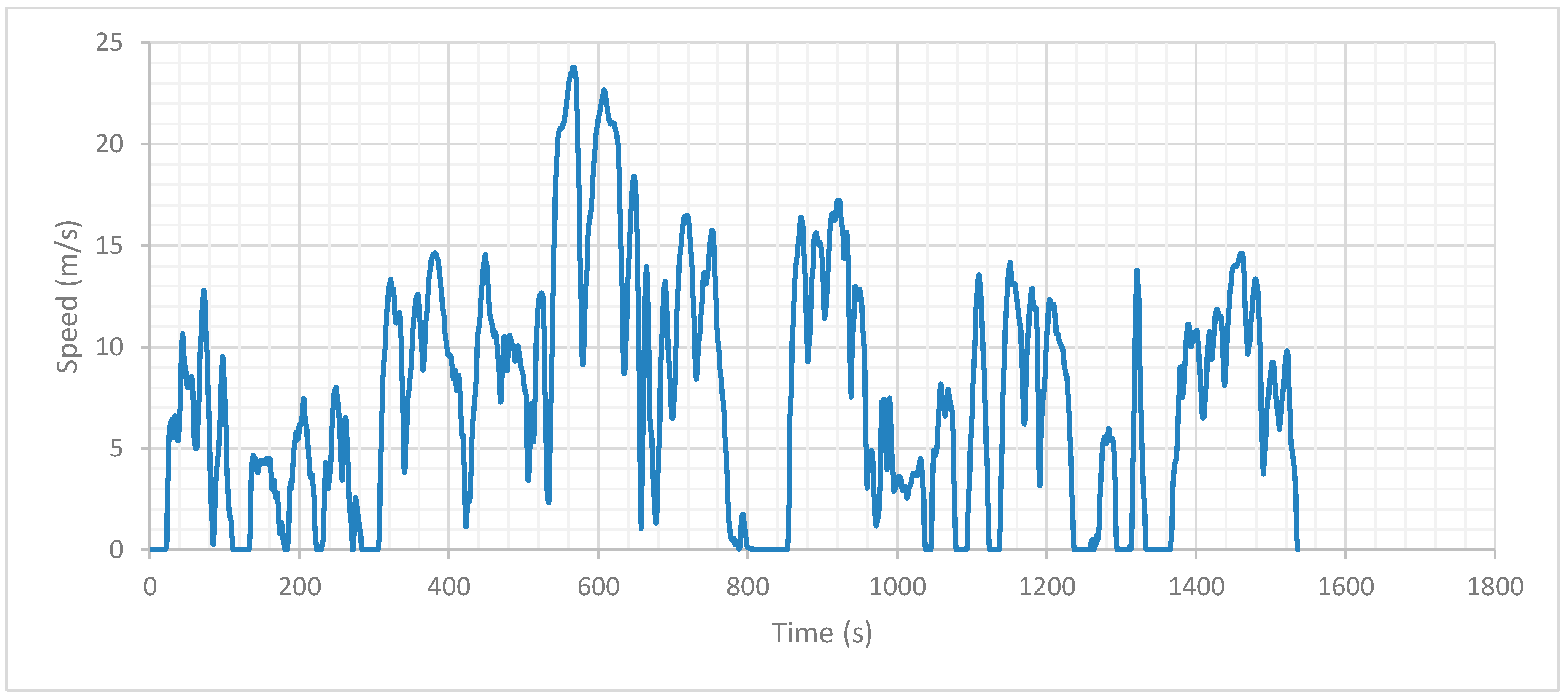
As regards the driving pattern for the estimation of energy consumption, calculations are performed on the basis of three different driving cycles: New European Driving Cycle (NEDC) [51], World Light Test Procedure (WLTP) [52], and All-Long Driving Cycle (ALDC) developed within the European research project “Ageing and efficiency Simulation & TEsting under Real world conditions for Innovative electric vehicle Components and Systems” (ASTERICS) [53]. NEDC is the driving cycle that had been adopted for the type-test approval in Europe up to 2017, while the WLTP is the current European type-test-approval cycle. Despite that the NEDC is no longer in force, it is included to allow comparison of energy/fuel reduction values with past studies (perhaps dealing with different powertrain technologies such as ICEV). On the other hand, the choice to adopt the standardized driving cycle at European level (WLTP) is due to the need for consistency, transparency, and comparability with present and future works. Finally, the ALDC was selected since it has been specifically developed to reproduce the real usage conditions of current Electric Vehicles within urban and suburban areas [54]. Table A2 in Appendix A reports the main descriptive parameters of the three drive cycles, while Appendix Figure A1 reports the speed profile of the ALDC.

2.2. Estimation of Reduction Values for Energy Consumption and Environmental Impact

The evaluation of mass-related energy absorption is carried out on the basis of consumption values obtained in the simulation modeling step. The calculation procedure provides that, for each vehicle case study, the energy absorption is estimated for the reference mass configuration and for four lightweight mass configurations, with respectively 5%, 10%, 15%, and 20% weight reduction with respect to the reference one. Then the mass-induced consumption is determined as the slope of the regression line of electricity absorption in function of mass (Figure A2 in Appendix A), and it is determined by means of the Energy Reduction Value (ERV) coefficient, according to the following equation:
E R V = Δ E C Δ M
where ERV = Energy Reduction Value (kWh/(100 km × 100 kg)); ΔEC = reduction in energy consumption achieved through vehicle mass reduction (kWh/100 km); and ΔM = 100 kg vehicle mass reduction.
Since powertrain resizing has a negligible impact on the energy saving of BEVs [55], the modeling is performed while assuming primary mass reduction only; that is, all vehicle parameters in the lightweight configurations remain unchanged with respect to the reference one with the sole exception of mass. The calculation section closes with the assessment of the environmental implications provided by mass reduction. Such an assessment is based on the modeling of energy reduction coefficients, and it provides that the ERVs are converted into Impact Reduction Value (IRV) coefficients by multiplying the mass-induced electricity consumption by a specific impact factor. The impact factor is defined as the Global Warming Potential (GWP) involved by the production of 1 kWh electricity through a specific grid mix, according to the following equation:
IRV = ERV   ×   GWP kWh
where IRV = Impact Reduction Value (kg CO2 eq/(100 km × 100 kg)); ERV = Energy Reduction Value (kWh/(100 km × 100 kg)); and GWPkWh = Global Warming Potential impact due to the production of 1 kWh electricity (kg CO2 eq/kWh).
The IRV is calculated by taking into account three distinct electricity grid mixes: Norwegian (NO), average European (EU28), and Polish (PL). The choice to consider Norwegian and Polish scenarios is made to have a comprehensive overview on the sustainability effects of the electricity supply chain. Indeed, these mixes are characterized by diametrically opposed energy and environmental profiles: Electricity produced through the Norwegian mix is almost completely from renewable resources, while the Polish grid mix is mainly based on fossil resources.

3. Results

Table 1 reports the ERV and IRV coefficients for all vehicle case studies and driving cycles, while Table 2 characterizes ERV/IRV in terms of minimum and maximum value, range max–min, arithmetic mean, and standard deviation (for both single classes and totality of car models). Table A3 in Appendix A provides the electricity consumption of vehicle case studies for each mass configuration.

3.1. Variability of Reduction Coefficients on Use Stage Boundary Conditions

Table 1 stresses that the ERV varies widely based on vehicle case study and driving cycle, with an overall variability range of 0.47–1.17 kWh/(100 km × 100 kg). Figure 4 shows the arithmetic mean of ERV over vehicle models per car class and driving cycle; the black bars in the section refer to all case studies that identify the maximum range of variation. The ALDC provides the highest mass-induced consumption (ERVALDC) for both single segments and the totality of vehicles: The arithmetic mean over all models is 0.97 kWh/(100 km × 100 kg), with an increase respectively of about 60% with respect to WLTP and NEDC. Figure 4 also stresses that ERVALDC has the greatest dispersion around the arithmetic mean (range min–max of 0.77–1.17 kWh/(100 km × 100 kg)) and standard deviation of 0.12 kWh/(100 km × 100 kg), with notably lower variability provided by WLTP and NEDC (Table 1). Despite the correlation mass-consumption is strongly influenced by technical features of the specific car model, the generally higher ERVs in the ALDC can be explained by two main reasons. The first and most important one is that the specific energy consumption (electricity per kilometer) involved by mass-dependent resistance factors (rolling and acceleration resistance) is greater in the ALDC than in NEDC and WLTP, due to the more dynamic run of this drive cycle. ALDC, in fact, does not present a prolonged “high speed” section, in which aerodynamic friction become predominant in comparison with other mass-related phenomena. The second explanation is the lower average efficiency over the entire cycle with which the electric motor operates in the ALDC than in NEDC and WLTP. This is because the car works under partial load conditions for a relevant share of total ALDC duration, due to the frequent speed fluctuations and the high accelerations that characterize the cycle. In this regard, simulations data show that the motor base efficiency is lower in the lightweight mass-configurations than in the reference one and that the efficiency decreases at mass reduction growing: The reason for this may be found in the lower motor load required by lightweight configurations to follow the given velocity profile. Therefore, it can be said that the energy-saving potential achievable through lightweighting is higher in the ALDC than in the other drive cycles.
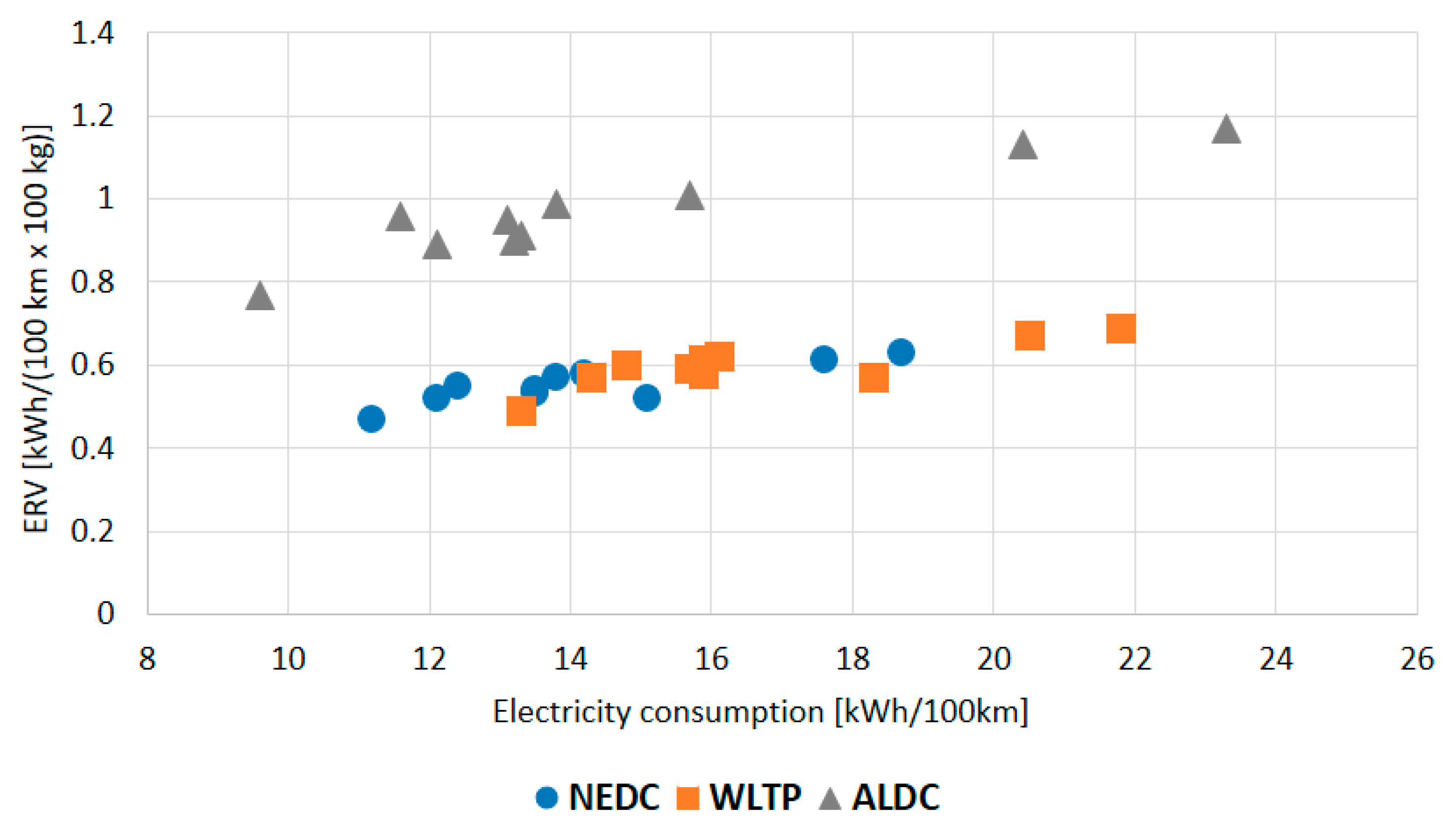
Concerning the dependence of ERV on vehicle size, Figure 4 highlights that the mass-induced consumption grows at car segment level increasing, with a percentage variation comprised within 17% and 24% (depending on drive cycle), passing from A/B to D/E class. This outcome is substantially confirmed by Figure 5, which reports the reduction values in function of electricity consumption. The ERV increases at energy-demand-growing and higher-class vehicles have greater consumption than lower segments: A/B-class provides the lowest electricity absorption (within 9.6–15.7 kWh/km, depending on vehicle model and driving cycle) and the lowest ERV (0.47–0.96 kWh/(100 km × 100 kg)), while D/E-class cars have the highest electricity absorption (14.2–23.3 kWh/km) and the highest ERVs (0.58–1.17 kWh/(100 km × 100 kg)). The growth of ERV with specific consumption generally occurs for all the drive cycles, and it is more pronounced for the ALDC than WLTP and NEDC.
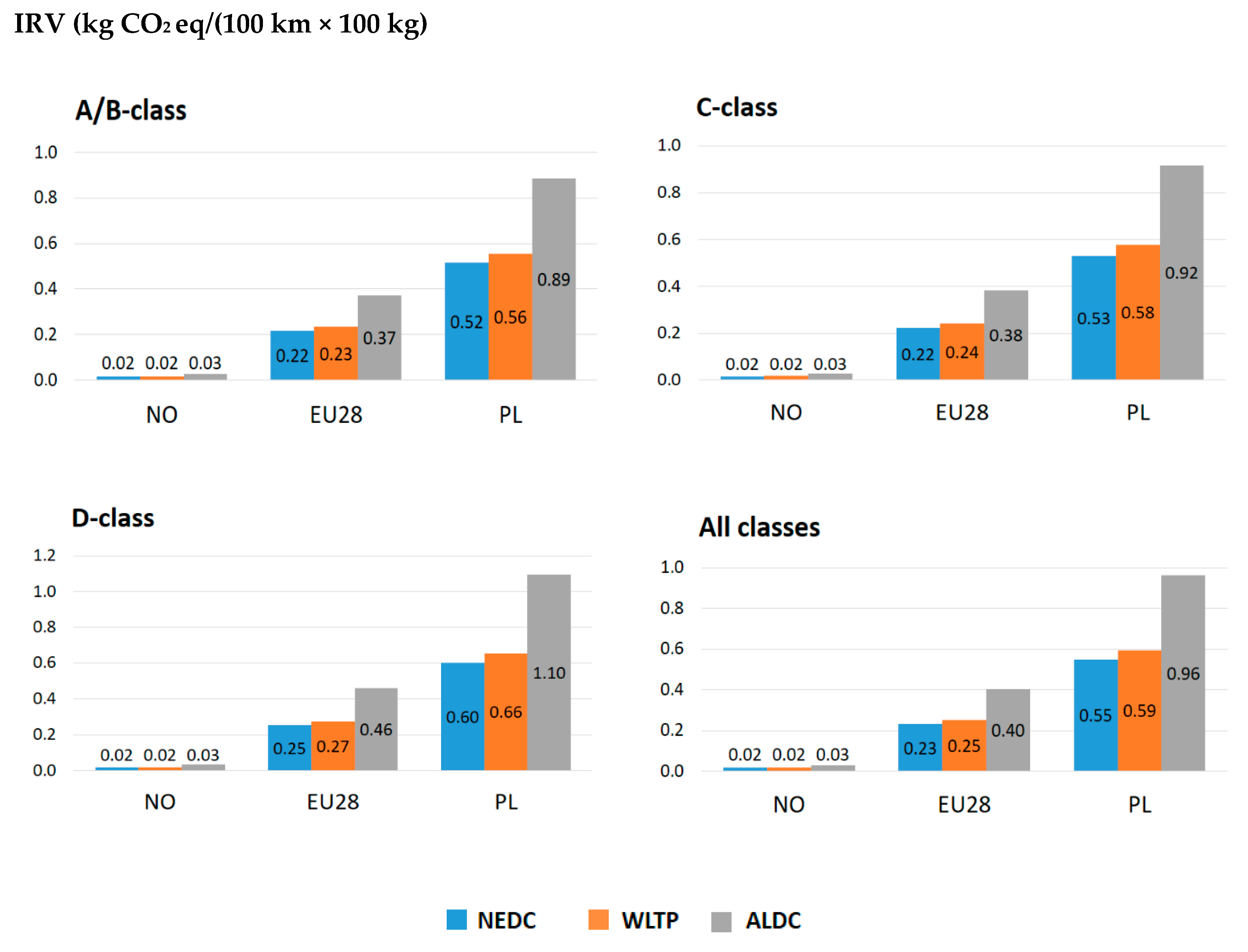
As regards the characterization of impact reduction, Figure 6 provides the arithmetic mean of IRV over car models per vehicle class and driving cycle. The first point is that, due to the analytical definition of IRV, the reduction values are directly dependent on the electricity grid mix. The choice to adopt Norwegian and Polish mixes allows us to evaluate diametrically opposite sustainability scenarios, among which all other possible alternatives are comprised. As a confirmation, the average IRV over all case studies is between the following:
  • 0.02 kg CO2 eq/(100 km × 100 kg) (IRVNEDC) and 0.03 kg CO2 eq/(100 km × 100 kg) (IRVALDC) when considering the Norwegian grid mix;
  • 0.55 kg CO2 eq/(100 km × 100 kg) (IRVNEDC) and 0.96 kg CO2 eq/(100 km × 100 kg) (IRVALDC) when considering the Polish grid mix.
Meanwhile, intermediate values are obtained for the average European grid mix. Results highlight that the variability of IRV based on electricity production is definitely high, especially if compared with the dependence on vehicle class and driving cycle. From the above, it is clear that the choice of the specific grid mix represents a decisive point for the effective convenience of a lightweight design solution.

3.2. Modeling Approach for ERV and IRV Estimation

This paragraph is aimed at refining a modeling method able to provide affordable values of ERV/IRV for real-world cars, taking into account the variability on the main vehicles’ technical features. Such an approach was developed by starting from mass reduction values resulting from simulations performed for the different case studies.
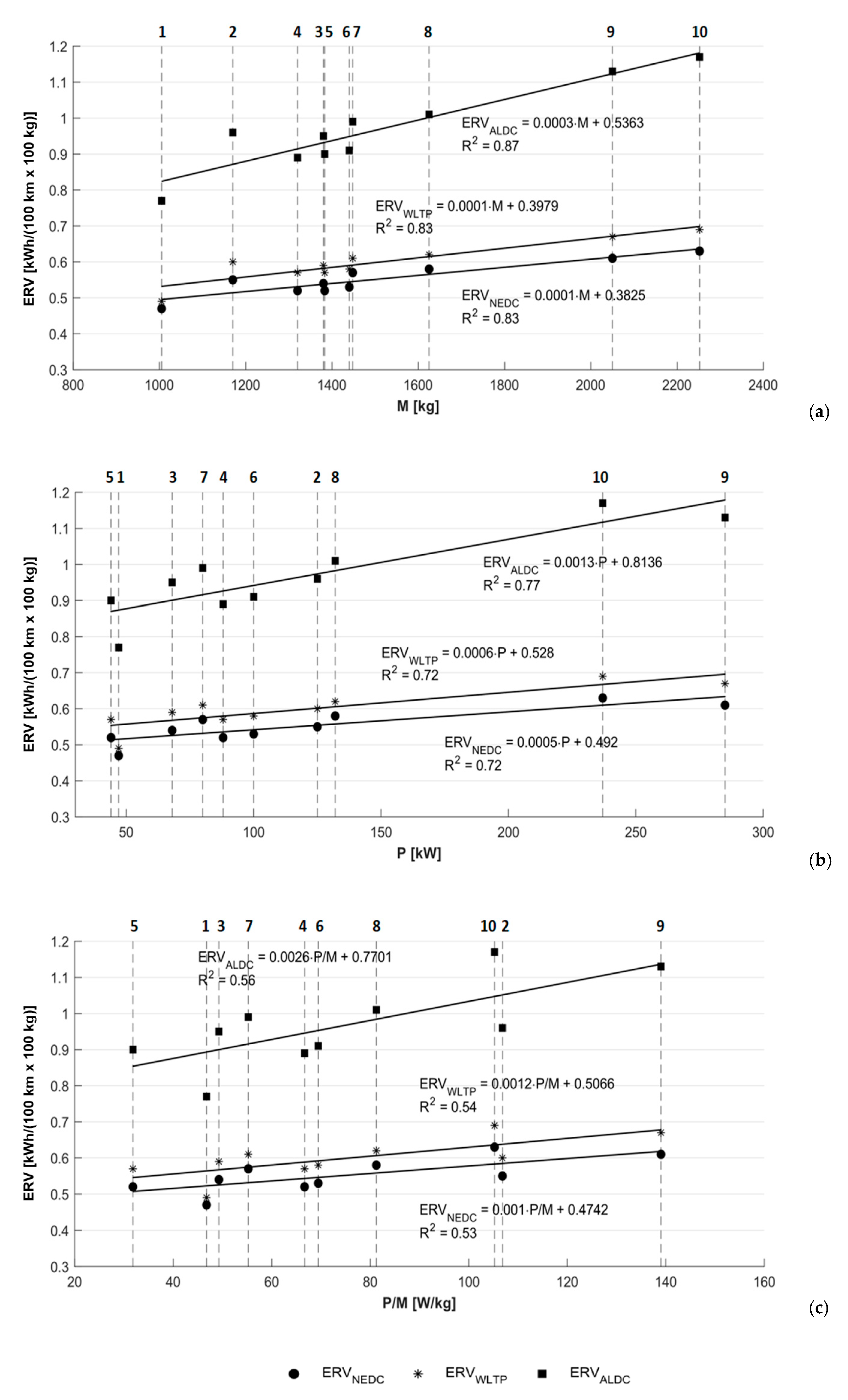
The first section of the paragraph investigates the variability of mass-induced energy consumption with respect to car technical features mass (M), maximum power (Pmax), and power-to-mass ratio (P/M). The effectiveness of the correlation is analyzed through regression lines of ERV in function of the three parameters. Figure 7 reports ERV as a function of M, Pmax, and P/M, with regression lines and related coefficients of determination for the driving cycles NEDC, WLTP, and ALDC.
First of all, it can be noted that the ERVs increase with the considered parameters and that the slope of the regression lines in the ALDC is significantly higher than in NEDC and WLTP. These results appear to be in accordance with average data presented in previous paragraph, as explained by the following:
  • Higher class-level case studies generally have higher M, Pmax, and P/M;
  • The greater mass-dependent resistance forces in the ALDC make that the ERV increases more rapidly at car size increasing with respect to the other driving cycles.
Concerning the correlation analysis, the values of R2 stress that the weaker dependence is detected for parameter P/M, whose coefficients of determination are around 0.55 for all the drive cycles. Higher R2 refers to Pmax (about 0.75), while the strongest correlation occurs for M, with R2 abundantly over 0.8 (0.83 for both NEDC and WLTP and 0.87 for ALDC). Based on previous considerations, the chosen approach for the modeling of mass-induced energy consumption of real-world vehicles is the use of regression lines of ERV in function of mass. Such a criterion allows us to estimate in a simple way the ERV for any generic case study only from the knowledge of vehicle weight. However, the model is composed by three equations (one for each driving cycle), without any indication on the choice of them. In this regard, the following has to be taken into account:
  • The NEDC had been the standardized driving cycle for European type approval tests until 2017, when it was replaced by the WLTP. However, the cycle is widely criticized to not represent the driving behavior of current real-world drivers and cars, since numerous studies show that actual on-road fuel consumption and emissions might be substantially higher than values determined through the NEDC [56,57,58,59].
  • The WLTP is a global, harmonized standard for determining the levels of fuel consumption/pollutants of both conventional and hybrid cars, as well as the range of fully Electric Vehicles.
  • The ALDC can be considered fully representative of actual usage conditions of current EVs, since it has been developed specifically for fully electric cars through testing campaigns carried out over urban and suburban driving routes of a large number of real vehicle users.
In the light of the above, the recommendation when evaluating the energy and environmental implications of lightweighting for a real-world case study is to assume three separate use-phase scenarios: One referred to ALDC, and the other ones referred to NEDC and WLTP. The first scenario should be used as the reference for the study, as it provides the actual and most affordable assessment. On the other hand, results obtained through the NEDC and WLTP should be considered as means of comparison with past and current studies that deal with alternative/competing solutions for the same applications. The equations of regression lines of ERV in function of mass are reported in Table 2 for the three driving cycles (ERVALDC, ERVNEDC, and ERVWLTP).
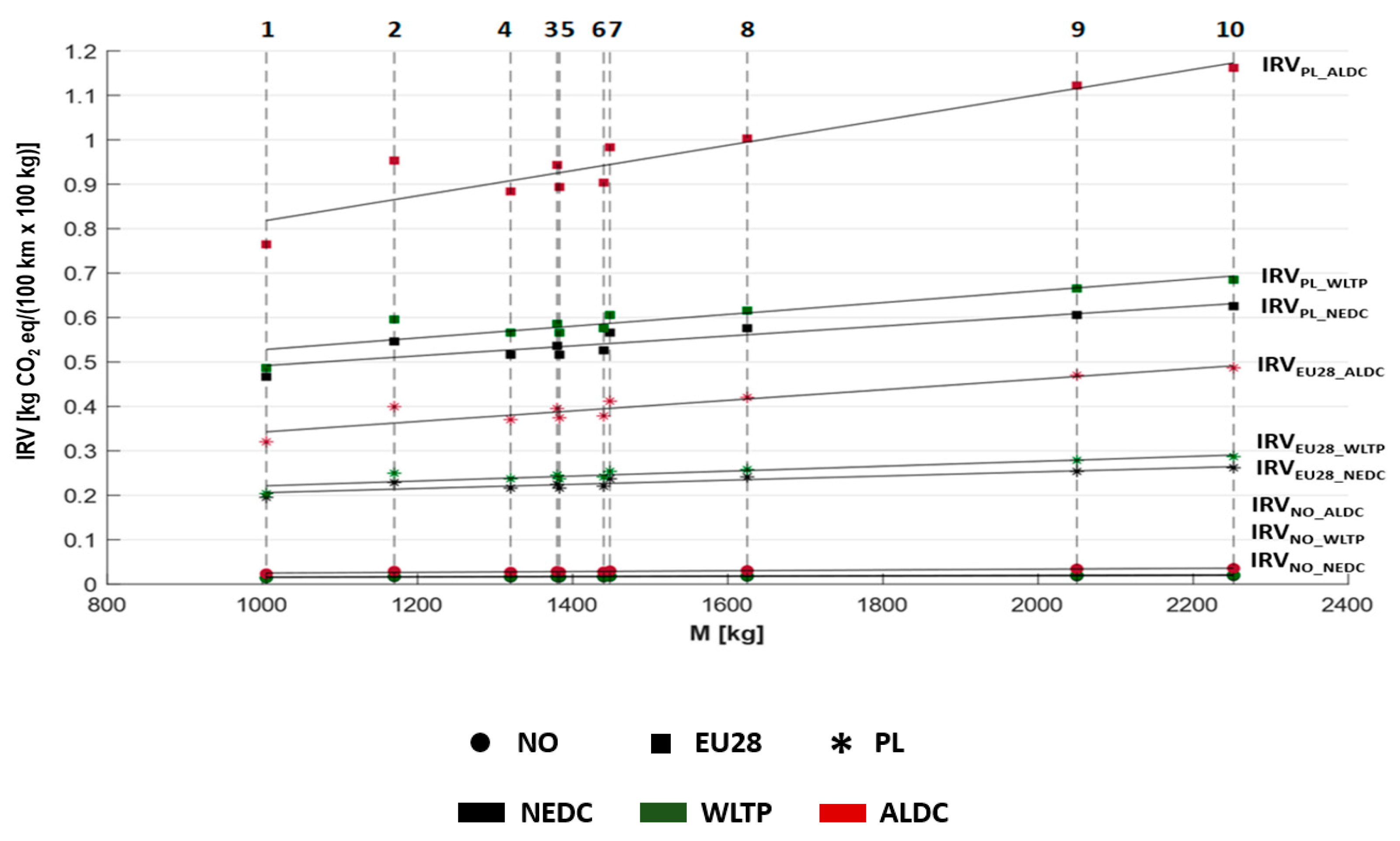
As regards the environmental assessment section, Figure 8 shows IRVs in function of M with related regression lines and R2 for the considered driving cycles. The figure reports only data in function of mass because the impact reduction coefficient has the same correlation of ERV with the considered parameters. The equations of regression lines are reported in Table 3 for the three driving cycles and the three electricity grid mixes. Another remarkable thing provided by the analysis of impact reduction coefficients is that the variability on electricity grid mix is notably higher with respect to the dependence on driving cycle. For example, assuming as reference the regression line of IRV in the average European grid mix and NEDC (IRVEU28_NEDC), the increase is higher when passing to the Poland mix while maintaining the driving cycle (IRVPL_NEDC) than when passing to ALDC while maintaining the grid mix (IRVEU28_ALDC).

3.3. Implementation of Modeling Approach on Real-Word Case Studies

This paragraph provides a practical example of the functionality of ERV/IRV modeling approach in the assessment of lightweighting within the electro-mobility field. Such an approach is applied to a series of sustainability case studies provided by Reference [60]:
  • These are comparative Life-Cycle Assessments (LCAs) of reference and innovative design solutions for different modules installed on a C-class EV;
  • The lightweight components are based on composites and hybrid materials and they have been specifically developed for fully electric cars;
  • The environmental analysis is carried out considering the entire Life Cycle (LC) of the modules and it is based on several impact categories, including the Global Warming Potential (GWP).
The comparative case studies are reviewed for the only GWP impact category by quantifying the LC mileage at which the novel design results environmentally preferable with respect to the reference one [60]. Such an LC distance is defined as the Break-Even Point (BEP), and it is determined by quantifying the impact variation in all LC stages involved by lightweighting: The GWP changes in production and End-of-Life (EoL) are directly taken from Reference [60], while the use phase is estimated through the ERV/IRV approach, using regression lines reported in Table 2. The following equation provides the analytical model for the calculation of BEP:
B E P = 10000   ×   Δ G W P P r o d + E o L I R V   ×   Δ M l i g h t
where BEP = Break-Even Point (km); ΔGWPProd+EoL = variation in Global Warming Potential impact due to lightweight design (kg CO2 eq); IRV = Impact Reduction Value (kg CO2 eq/(100 km × 100 kg)); and ΔMlight = variation in vehicle mass due to lightweight design (kg).
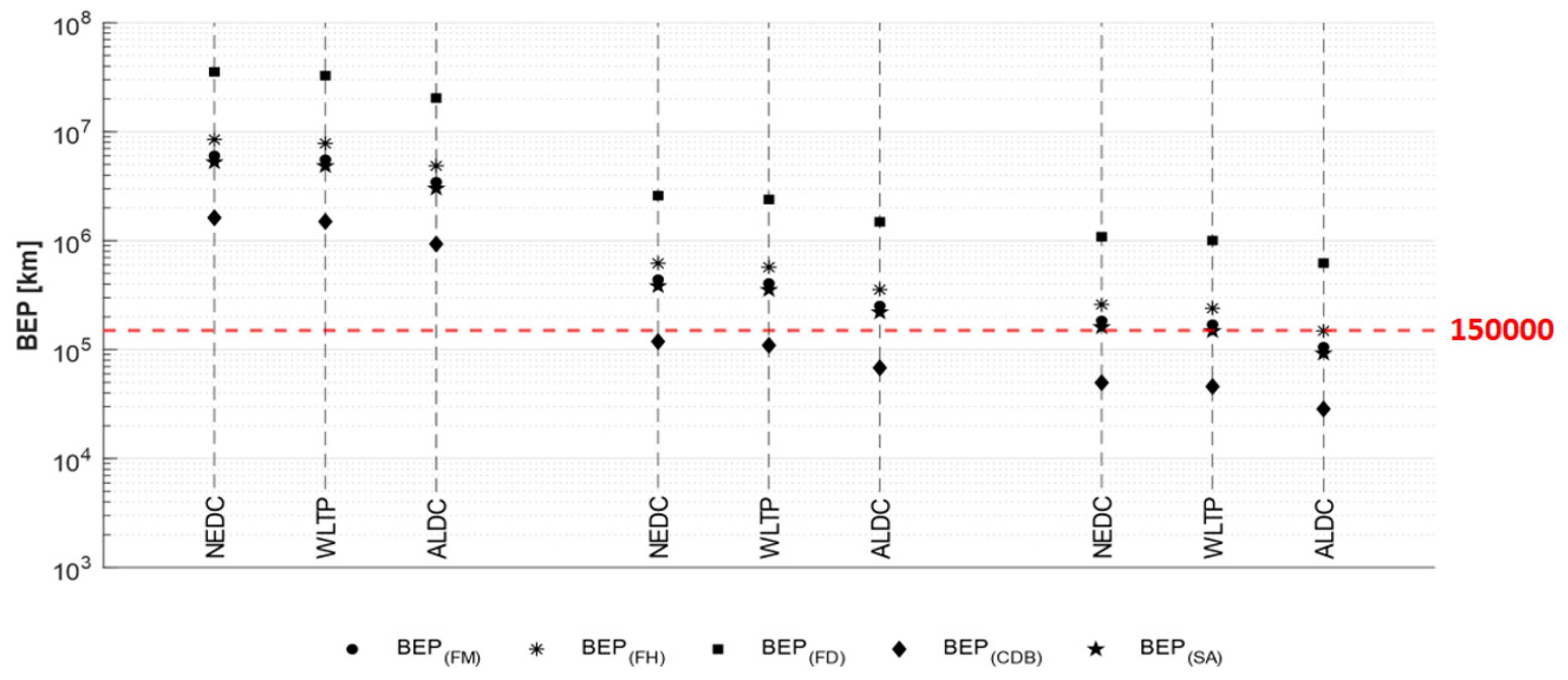
Table A4 in Appendix A reports ΔGWPProd+EoL and ΔM for all the considered sustainability case studies, including a brief description of baseline and innovative design solutions, as well as the main technical features of the reference car model for the modules. Figure 9 shows BEP for the five components taking into account all possible combinations between driving cycles and electricity grid mixes (numerical data are reported in Table A5 in Appendix A). The considered modules are Front Module (FM), Front Hood (FH), Front Door (FD), Cross Dashboard Beam (CDB), and Suspension Arm (SA). The diagram reveals that, when considering the Norwegian scenario, for all case studies, BEP is greatly higher than the reference LC mileage assumed by [60] (150,000 km), with a variability comprised between 35 million kilometers (referred to FD module in the NEDC) and 0.93 million kilometers (referred to CDB module in the ALDC). Therefore, a lightweight designs appear to be definitely not convenient from an environmental point of view, as weight reduction enables low mass-specific impact saving due to the very small GWP intensity of the Norwegian grid mix. BEPs are notably lower when considering the European scenario, even if the only component for which the novel alternative results preferable (in all driving cycles) is CDB. However, BEP for SA and FM in the ALDC are not so far from 150,000 km (respectively about 220,000 and 250,000 km). Finally, the analysis based on the Polish grid mix involves a further decrease of BEP due to the very high fossil energy intensity of the cycle. Indeed, lightweighting appears to be an effective strategy for CDB (in all drive cycles), SA (in WLTP and ALDC), and FM (in ALDC), with BEPs just above the LC threshold for the other modules and driving cycles (within the range 160,000–260,000 km); the only exception is represented by FD, which provides a BEP notably higher (around 620,000–1,080,000 km).
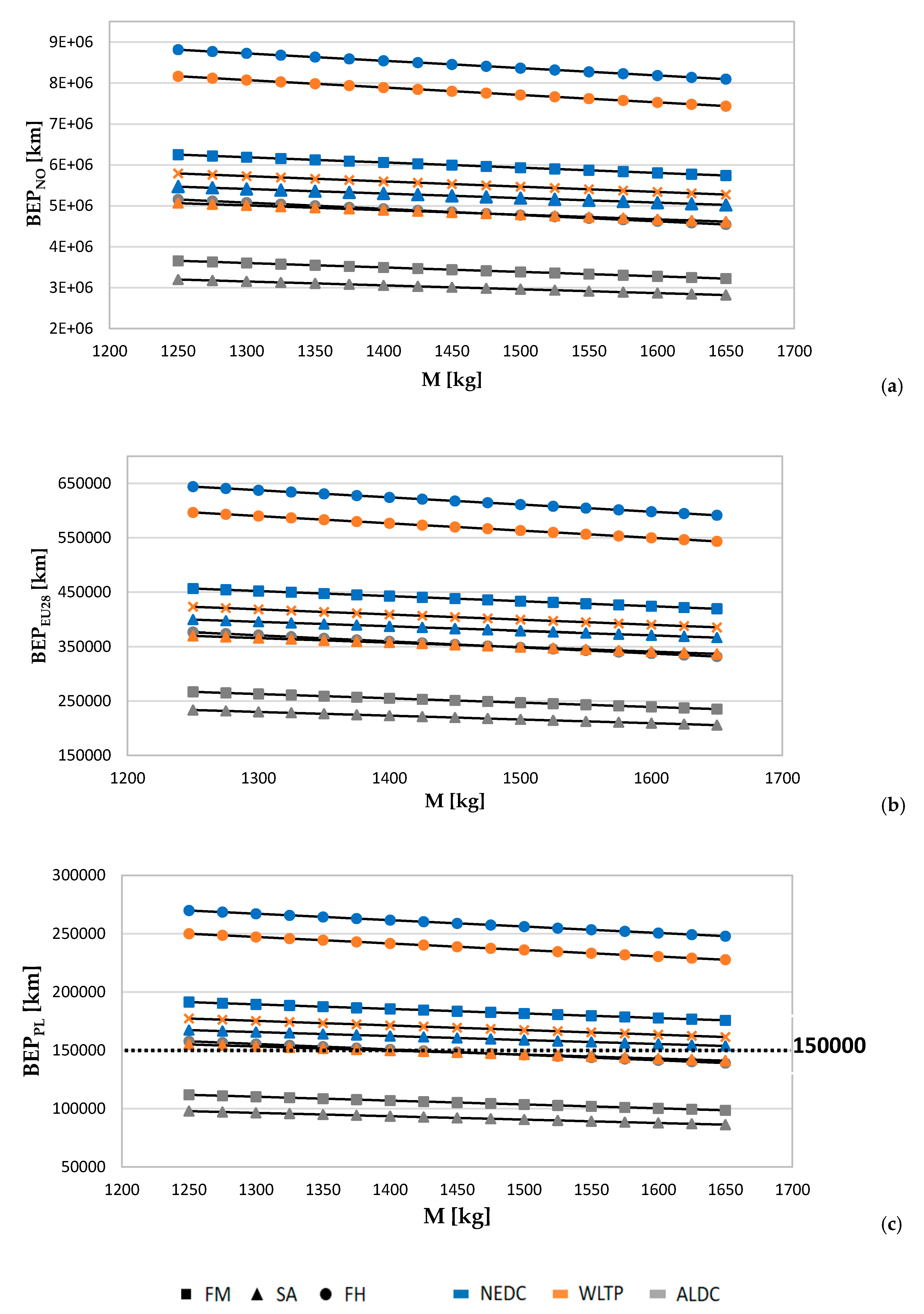
The environmental section is completed by the analysis of the influence of vehicle model on BEP. Figure 10 reports BEP in function of car mass for the sustainability case studies FM, FH, and SA, respectively, for Norwegian, average European, and Polish grid mixes and including all the considered driving cycles. As the design solutions refer to a C-class vehicle, it is chosen to investigate the mass range 1250–1650 kg, which is found to be representative of medium-size EV’s segment. Table A6 in Appendix A reports BEP for the considered case studies, assuming M = 1250 kg and M = 1650 kg.
The diagrams reveal that, beyond the inherent features of the specific modules, the Norwegian mix (Figure 10a) provides the highest absolute variability of BEP with respect to car mass (BEP variability comprised within 350,000 and 750,000 km based on case study and drive cycle). The reason for this is that BEPs are very high due to the definitely low embodied GWP of electricity production. Indeed, the Break-Even is comprised between two and nine million kilometers, thus evidencing that the lightweight options are far from an effective profitability, even for cars with great mass. As regards the average European mix (Figure 10b), BEPs are significantly lower than the Norwegian one. However, the Break-Even is not reached within the 150,000 km threshold for any of the innovative design alternatives. That said, BEP for SA module in the ALDC with a 1650 kg car is about 200,000 km, which could be also reached by an EV. Lastly, Figure 10c shows that the Polish electricity grid mix involves the lowest absolute variability of BEP with the mass (BEP variability comprised within 10,000 and 25,000 km, depending on case study and drive cycle). As the Break-Even mileages have the same order (within the range of 80,000–270,000 km) than the assumed LC distance, the dependence on vehicle model becomes decisive to establish the effective environmental convenience of the lightweight solutions. As a confirmation, BEP for the SA module in the WLTP and the FH module in the ALDC results above 150,000 km when considering low-mass cars (respectively about 155,000 and 158,000 km for 1250 kg EVs), while high-mass vehicles provide a BEP which is below the LC limit (respectively around 141,000 and 139,000 km for 1650 kg cars). This means that these solutions result in being environmentally advantageous for high-size models, while they are not when applied to entry-level C-class vehicles. Concerning the other modules/driving cycles, the variability of BEP with car weight does not involve a threshold crossing. Two opposite examples for this are the FH module in the NEDC and the SA module in the ALDC. When passing from lower to upper mass limit, the BEP for the FH reduces by about 22,000 km, without, however, approaching significantly the 150,000 km (BEP varies from about 270,000 to 248,000 km). On the other hand, the change for the SA module (around 12,000 km) entails a significant increase in the convenience of the lightweight solution (BEP ranges from about 98,000 km to 86,000 km). In the light of previous considerations, it can be concluded that the variability of BEP on vehicle model represents a key factor when engaging with the following:
  • Dealing with lightweight case studies characterized by a low mass-specific GWP increase in production and EoL (ΔGWPProd+EoL/ΔMlight);
  • Assuming fossil-intensive electricity grid mixes and driving cycles with highly dynamic run.

4. Conclusions

To date, fuel-mass correlation has been widely studied for ICE light duty vehicles, while great margins of investigation still exist for advanced powertrain technologies, especially for pure electric cars. The study refines a comprehensive framework for the estimation of EVs’ mass-induced consumption to provide support in the energy and sustainability assessment of lightweight design solutions when physical tests or computer-aided simulations are not available. A simplified method to estimate consumption-weight correlation is proposed based on the calculation of ERV coefficients, expressed in kWh/(100 km × 100 kg). The simulations are performed for a set of car case studies, using technical features of specific 2019 European market EV models, chosen as a representative of different segments (A/B, C, and D/E). The ERV coefficients are estimated according to three driving cycles, both internationally standardized and developed in research activities (NEDC, WLTP, and ALDC), to assess the influence of different driving styles on mass-induced consumption. The ERV is finally converted into the IRV coefficient, which expresses the GWP saving achievable through a 100 kg mass decrease and it is quantified for Norwegian, average European, and Polish grid mixes. The ERVs obtained for the different case studies show that there is a wide variability based on vehicle model and driving cycle, with values in the range of 0.47–1.17 kWh/(100 km × 100 kg). Beyond the influence of the specific car model, results stress that ERV is closely related to car consumption (economy) and it grows at car size increasing: For example, the average ERVALDC in the A/B class is 0.89 kWh/(100 km × 100 kg), while it reaches 1.10 kWh/(100 km × 100 kg) for the D/E segment, with intermediate value for C class. As a result, a given amount of lightweighting (kilograms saved) provides the most benefit when applied to upper-level class EVs with high energy consumption. Concerning the influence of driving cycle, the ERV is notably higher for the ALDC than NEDC and WLTP, because of the great dynamics of the cycle (high acceleration/deceleration), which makes bigger the mass-induced energy consumption. The analysis of the dependence of ERV on the main vehicle technical features highlights that there is a strong correlation with car mass, based on which an analytical method is refined for providing affordable values for any real-life case study. Such a criterion allows us to thoroughly assess weight-related consumption when dealing with the comparison between reference and lightweight solutions from both energy and sustainability point of view. The ERV/IRV modeling approach is finally applied to a series of lightweight case studies from the literature, where the profitability of innovative solutions is assessed through the quantification of BEP. These case studies refer to several design solutions that strongly differ both in terms of technical features (materials and technologies used) and application field/boundary conditions (car size, driving cycle, and electricity grid mix). Results show that BEP is strongly influenced by vehicle model, especially when assuming fossil-intensive electricity grid mixes and driving cycles with highly dynamic run. This leads to the conclusion that a careful car model-specific approach is recommended, thus highlighting the utility and usability of the refined method.

Author Contributions

Conceptualization, F.D.P.; Data curation, F.D.P. and L.B.; Formal analysis, F.D.P. and A.A.; Investigation, F.D.P.; Methodology, F.D.P.; Software, F.D.P., L.B. and A.A.; Supervision, M.D.; Validation, M.D.; Writing—original draft, F.D.P. All authors have read and agreed to the published version of the manuscript.

Funding

This research received no external funding.

Conflicts of Interest

The authors declare no conflict of interest.

Abbreviations

ALDCAll-Long Driving Cycle
ASTERICS“Ageing and efficiency Simulation & TEsting under Real world conditions for Innovative electric vehicle Components and Systems”
BEVBattery Electric Vehicle
CDBCrash Dashboard Beam
EoLEnd-of-Life
ERVEnergy Reduction Value
EVElectric Vehicle
FDFront Door
FHFront Hood
FMFront Module
FRVFuel Reduction Value
FTPFederal Test Procedure
GWPGlobal Warming Potential
ICEVInternal Combustion Engine
IRVImpact Reduction Value
LCLife Cycle
LCALife-Cycle Assessment
NEDCNew European Driving Cycle
PIDProportional–Integral–Derivative
PMSMPermanent Magnet Synchronous Motor
SASuspension Arm
WLTPWorldwide Harmonized Light-Duty Test Procedure

Appendix A

Table A1. Technical features of BEV models assumed as reference for the considered case studies.
Case StudyVehicle ModelMass (kg)Power (kW)Power-to-Mass Ratio (W/kg)
1Mitsubishi I-MIEV10054747
2BMW i31170125107
3Renault Zoe13806849
4Hyundai Sonic13208867
5Renault Kangoo ZE13834432
6Volkswagen e-Golf144010069
7Nissan Leaf14488055
8Mercedes B-class162513281
9Tesla model-S2050285139
10Tesla model-X2252237105
Table A2. Main descriptive parameters for the considered drive cycles.
Descriptive Parameters of Driving Cycles
NEDCWLTPALDC
GeneralDuration (s)118018001536
Distance (km)11.0323.2711.57
Mean velocity (km/h)33.646.527.1
Max velocity (km/h)120.0131.385.6
Stop phases (null)14911
DurationsStop (s)280226210
Constant driving (s)47566114
Acceleration (s)247789624
Deceleration (s)178719588
SharesStop (%)23.712.613.7
Constant driving (%)40.33.77.4
Acceleration (%)20.943.840.6
Deceleration (%)15.139.938.3
DynamicMean positive acceleration (m/s2)0.590.410.55
Max positive acceleration (m/s2)1.041.673.25
Mean positive “vel * acc” (acceleration phases) (m2/s3)4.974.544.56
Max positive “vel * acc” (m2/s)9.2221.0129.29
Mean deceleration (m/s2)−0.82−0.45−0.58
Min deceleration (m/s2)−1.39−1.50−4.78
Relative positive acceleration (m/s3)0.1110.1530.271
Figure A1. Speed profile of the ALDC.
Machines 08 00051 g0a1
Figure A2. Energy consumption in function of mass with regression lines and ERV coefficient.
Machines 08 00051 g0a2
Table A3. Electricity consumption of vehicle case studies.
Electricity Consumption (kWh/100 km)
Vehicle ClassCase StudyNEDCWLTPALDC
Reference5% Lightweight10% Lightweight15% Lightweight20% LightweightReference5% Lightweight10% Lightweight15% Lightweight20% LightweightReference5% Lightweight10% Lightweight15% Lightweight20% Lightweight
A/B111.211.010.810.710.513.313.112.912.812.69.69.39.08.78.4
212.412.212.011.711.514.814.514.214.013.711.611.210.810.410.0
313.513.313.012.712.515.715.415.214.914.613.112.612.111.711.2
C412.111.911.611.411.114.314.013.713.413.112.111.611.210.710.3
515.114.814.614.314.118.318.017.717.417.213.212.712.311.811.4
613.513.212.912.612.315.915.615.31514.713.312.812.311.811.3
713.813.513.212.912.615.915.615.314.914.613.813.212.712.211.6
D/E814.213.813.413.012.716.115.715.314.914.515.715.114.413.813.2
917.617.216.816.416.020.520.019.619.118.720.419.618.918.117.4
1018.718.217.717.216.721.821.220.720.219.723.322.321.520.619.7
Table A4. Main technical and sustainability features of the considered sustainability case studies.
Case StudyMaterialsTechnologiesΔGWPProd+EoL
(GWPRef − GWPLight)
(kg CO2 eq)
ΔMlight (MRef − MLight) (kg)
FMReferenceAluminum; steelStamping and bending;
deep drawing
130.2−13.1
LightweightAluminum; high-strength steel; PA410 Carbon Fiber reinforced; steelExtrusion and forming; thermoforming; airborne winding; deep drawing
and drilling; bending
FHReferenceSteel Stamping and bending71.6−5.1
LightweightAluminum; epoxy resin Carbon Fiber reinforcedMetal stamping;
compression molding
FDReferenceSteel; aluminumStamping and bending83.9−1.4
LightweightAluminum;
Polyamide410 Carbon Fiber reinforced
Metal stamping; CF-airborne; thermoforming
CDBReferenceSteelStamping and bending11.5−4.3
LightweightAluminum; Polyamide410 Carbon/Glass Fiber reinforcedMetal stamping; injection molding; thermoforming
SAReferenceSteelForging19.0−2.2
LightweightAluminum; Vinyl Ester Carbon Fiber/reinforcedForging; advanced sheet compression molding
Reference car modelVolkswagen e-Golf
Mass = 1440 (kg)
Power = 100 (kW)
Power-to-mass ratio = 69 (W/kg)
Table A5. BEP for the considered sustainability case studies.
Break-Even Point (BEP) (km)
Electricity Grid MixDriving CycleModules
FMFHFDCDBSA
NONEDC6,005,1418,468,38835,432,5441,623,0025,252,987
WLTP5,541,1547,814,07832,694,8491,497,6014,847,115
ALDC3,446,0794,859,62520,333,137931,3683,014,452
EU28NEDC438,837618,8442,589,301118,604383,872
WLTP404,930571,0292,389,239109,440354,212
ALDC251,829355,1261,485,88368,061220,287
PLNEDC183,843259,2541,084,74349,687160,817
WLTP169,639239,2231,000,93045,848148,391
ALDC105,499148,774622,48528,51392,285
Table A6. BEP for the considered case studies assuming M = 1250 kg and M = 1650 kg.
Break-Even Point (BEP) (km)
Electricity Grid MixDriving CycleModules
FMFHSA
M = 1250 kgM = 1650 kgM = 1250 kgM = 1650 kgM = 1250 kgM = 1650 kg
NONEDC6,250,4665,931,6228,814,3438,364,7125,467,5855,188,676
WLTP5,789,9715,466,9638,164,9587,709,4565,064,7684,782,217
ALDC3,655,7533,384,7745,155,3054,773,1743,197,8642,960,826
EU28NEDC456,765433,465644,125611,267399,554379,173
WLTP423,113399,509596,670563,383370,118349,470
ALDC267,151247,349376,734348,809233,690216,368
PLNEDC191,354181,592269,845256,080167,386158,848
WLTP177,256167,367249,964236,020155,054146,404
ALDC111,918103,622157,826146,12797,90090,644

References

  1. Intergovernmental Panel on Climate Change. Climate Change 2014: Impacts, Adaptation, and Vulnerability; Cambridge University Press: Cambridge, UK; New York, NY, USA, 2014; Volume 1. [Google Scholar]
  2. U.S. Environmental Protection Agency. DRAFT Inventory of U.S. Greenhouse Gas. Emissions and Sinks: 1990−2016; U.S. Environmental Protection Agency: Washington, DC, USA, 2018.
  3. Intergovernmental Panel on Climate Change. Climate Change 2013: The Physical Science Basis, Working Group I Contribution to the Fifth Assessment; Cambridge University Press: Cambridge, UK, 2013. [Google Scholar]
  4. Mashayekh, Y.; Jaramillo, P.; Samaras, C.; Hendrickson, C.T.; Blackhurst, M.; MacLean, H.L.; Matthews, H.S. Potentials for sustainable transportation in cities to alleviate climate change impacts. Environ. Sci. Technol. 2012, 46, 2529–2537. [Google Scholar] [CrossRef] [PubMed]
  5. Milovanoff, A.; Kim, H.C.; De Kleine, R.; Wallington, T.J.; Posen, I.D.; MacLean, H.L. A Dynamic Fleet Model of U.S Light-Duty Vehicle Lightweighting and Associated Greenhouse Gas Emissions from 2016 to 2050. Environ. Sci. Technol. 2019, 53, 2199–2208. [Google Scholar] [CrossRef] [PubMed]
  6. Gonzalez Palencia, J. Energy use and CO2 emissions reduction potential in passenger car fleet using zero emission vehicles and lightweight materials. Energy 2012, 48, 548–565. [Google Scholar] [CrossRef]
  7. Tisza, M.; Czinege, I. Comparative study of the application of steels and aluminium in lightweight production of automotive parts. Int. J. Lightweight Mater. Manuf. 2018, 1, 229–238. [Google Scholar] [CrossRef]
  8. Das, S.; Graziano, D.; Upadhyayula, V.K.K.; Masanet, E.; Riddle, M.; Cresko, J. Vehicle lightweighting energy use impacts in U.S. light-duty vehicle fleet. Sustain. Mater. Technol. 2016, 8, 5–13. [Google Scholar] [CrossRef] [Green Version]
  9. Luk, J.; Kim, H.C.; De Kleine, R.; Wallington, T.J.; MacLean, H. Impact of powertrain type on potential life cycle greenhouse gas emission reduction from a real world lightweight glider. SAE Tech. Pap. Ser. 2017, 1–8. [Google Scholar] [CrossRef]
  10. Modaresi, R.; Pauliuk, S.; Løvik, A.N.; Muller, D.B. Global Carbon Benefits of Material Substitution in Passenger Cars until 2050 and the Impact on the Steel and Aluminum Industries. Environ. Sci. Technol. 2014, 48, 10776–10784. [Google Scholar] [CrossRef] [Green Version]
  11. Koffler, C.; Rodhe-Branderburger, K. On the calculation of fuel savings through lightweight design in automotive life cycle assessments. Int. J. Life Cycle Assess. 2010, 15, 128–135. [Google Scholar] [CrossRef]
  12. Sah, S.; Bawase, M.; Saraf, M. Light-weight Materials and their Automotive Applications. SAE Tech. Pap. 2014, 28, 25. [Google Scholar] [CrossRef]
  13. Ferreira, V. Lightweight automotive components based on nano-diamond-reinforced aluminium alloy: A technical and environmental evaluation. Diam. Relat. Mater. 2019, 2019, 92. [Google Scholar]
  14. Mayyas, A.T.; Qattawi, A.; Mayyas, A.R.; Omar, M.A. Life cycle assessment based selection for a sustainable lightweight body-in-white design. Energy 2012, 39, 412–425. [Google Scholar] [CrossRef]
  15. Poulikidou, S.; Jerpdal, L.; Bjorklund, A.; Åkermo, M. Environmental performance of self-reinforced composites in automotive applications. Case study on a heavy truck component. Mater. Des. 2016, 103, 321–329. [Google Scholar] [CrossRef]
  16. Kim, H.C.; Wallington, T.J. Life-Cycle Energy and Greenhouse Gas Emission Benefits of Lightweighting in Automobiles: Review and Harmonization. Environ. Sci. Technol. 2013, 47, 6089–6097. [Google Scholar] [CrossRef]
  17. Lewis, A.M.; Kelly, J.C.; Keoleian, G.A. Vehicle lightweighting vs. electrification: Life cycle energy and GHG emissions results for diverse powertrain vehicles. Appl. Energy 2014, 126, 13–20. [Google Scholar] [CrossRef]
  18. Egede, P. Environmental Assessment of Lightweight Electric Vehicles; Springer International Publishing: Cham, Switzerland, 2017. [Google Scholar]
  19. Alonso, E.; Lee, T.M.; Bjelkengren, C.; Roth, R.; Kirchain, R.E. Evaluating the Potential for Secondary Mass Savings in Vehicle Lightweighting. Environ. Sci. Technol. 2012, 46, 2893–2901. [Google Scholar] [CrossRef] [PubMed]
  20. Egede, P. Sustainable Production, Life Cycle Engineering and Management. In Environmental Assessment of Lightweight Electric Vehicles, 1st ed.; Springer International Publishing: Cham, Switzerland, 2016. [Google Scholar]
  21. Vinodh, S.; Jayakrishna, K. Environmental impact minimisation in an automotive component using alternative materials and manufacturing processes. Mater. Des. 2011, 32, 5082–5090. [Google Scholar] [CrossRef]
  22. Raugei, M.; Morrey, D.; Hutchinson, A.; Winfield, P. A coherent life cycle assessment of a range of lightweighting strategies for compact vehicles. J. Clean. Prod. 2015, 108, 1168–1176. [Google Scholar] [CrossRef] [Green Version]
  23. Weimar, E.; Finkbeiner, M. Statistical analysis of empirical lifetime mileage data for automotive LCA. Int. J. Life Cycle Assess. 2016, 21, 215–223. [Google Scholar] [CrossRef]
  24. Bian, J.; Mohrbacher, H.; Zhang, J.S.; Zhao, Y.T.; Lu, H.Z.; Dong, H. Application potential of high performance steels for weight reduction and efficiency increase in commercial vehicles. Adv. Manuf. 2015, 3, 27–36. [Google Scholar] [CrossRef] [Green Version]
  25. Faßbender, S.; Broöckerhoff, D.E.; Eckstein, L.; Hartmann, B.; Urban, P. Investigation of the Trade-Off between Lightweight and Battery Cost for an Aluminum-Intensive Electric Vehicle; Report 106330; Forschungsgesellschaft Kraftfahrwesen mbH Aachen: Aachen, Germany, 2012. [Google Scholar]
  26. Schuh, G.; Korthals, K.; Backs, M. Environmental Impact of Body Lightweight Design in the Operating Phase of Electric Vehicles. In Proceedings of the 20th CIRP International Conference on Life Cycle Engineering, Singapore, 17–19 April 2013; Springer: Singapore. [Google Scholar]
  27. Wilhelm, E.; Hofer, J.; Schenler, W.; Guzzella, L. Optimal implementation of lightweighting and powertrain efficiency in passengers’ vehicles. Transport 2012, 27, 237–249. [Google Scholar] [CrossRef]
  28. Pagerit, S.; Sharer, P.; Rousseau, A. Fuel Economy Sensitivity to Vehicle Mass for Advanced Vehicle Powertrains. SAE Tech. Pap. 2006, 1, 665. [Google Scholar]
  29. Ridge, L. EUCAR—Automotive LCA Guidelines—Phase 2. SAE Tech. Pap. 1998. [Google Scholar] [CrossRef]
  30. United States Environmental Protection Agency. New Fuel Economy and Environment Labels for a New Generation of Vehicles; EPA-420-F-11-017; United States Environmental Protection Agency: Washington, DC, USA, 2011.
  31. Muttana, S.B.; Sardar, A. Lightweighting of Battery Electric Cars: An Impact Analysis Using Indian Driving Cycle. SAE Tech. Pap. Ser. 2013. [Google Scholar] [CrossRef]
  32. Kim, H.C.; Wallington, T.J.; Sullivan, J.L.; Keoleian, G.A. Life cycle assessment of vehicle lightweighting: Novel mathematical methods to estimate use-phase fuel consumption. Environ. Sci. Technol. 2015, 49, 10209–10216. [Google Scholar] [CrossRef]
  33. Kelly, J.C.; Sullivan, J.L.; Burnham, A.; Elgowainy, A. Impacts of vehicle weight reduction via material substitution on life-cycle greenhouse gas emissions. Environ. Sci. Technol. 2015, 49, 12535–12542. [Google Scholar] [CrossRef]
  34. Hofer, J.; Wilhelm, E.; Schenler, W. Comparing the mass, energy, and cost effects of lightweighting in conventional and electric passenger vehicles. J. Sustain. Dev. Energy Water Environ. Syst. 2014, 2, 284–295. [Google Scholar] [CrossRef] [Green Version]
  35. Del Pero, F.; Delogu, M.; Pierini, M. The effect of lightweighting in automotive LCA perspective: Estimation of mass-induced fuel consumption reduction for gasoline turbocharged vehicles. J. Clean. Prod. 2017, 154, 566–577. [Google Scholar] [CrossRef]
  36. Delogu, M.; Del Pero, F.; Pierini, M. Lightweight design solutions in the automotive field: Environmental modelling based on Fuel Reduction Value applied to diesel turbocharged vehicles. Sustainability 2016, 8, 1167. [Google Scholar] [CrossRef] [Green Version]
  37. Kim, H.C.; Wallington, T.J. Life cycle assessment of vehicle lightweighting: A physics-based model of mass-induced fuel consumption. Environ. Sci. Technol. 2013, 47, 14358–14366. [Google Scholar] [CrossRef]
  38. An, F.; Santini, D.J. Mass Impacts on Fuel Economies of Conventional vs. Hybrid Electric Vehicles. In Proceedings of the SAE World Congress, Detroit, MI, USA, 8−11 March 2004. [Google Scholar]
  39. Redelbach, M.; Klotzke, M.; Friedrich, H.E. Impact of Lightweight Design on Energy Consumption and Cost Effectiveness of Alternative Powertrain Concepts. In Proceedings of the European Vehicle Congress (EEVC), Brussel, Belgium, 19–22 November 2012. [Google Scholar]
  40. Casadei, A.; Broda, R. Impact of Vehicle Weight Reduction on Fuel Economy for Various Vehicle Architectures; Project FB769; Ricardo Inc.: Shoreham-by-Sea, UK, 2008. [Google Scholar]
  41. Wohlecker, R.; Johannaber, M.; Espig, M. Determination of Weight Elasticity of Fuel Economy for ICE, Hybrid and Fuel Cell Vehicles. SAE Tech. Pap. 2007, 1, 343. [Google Scholar]
  42. U.S. Environmental Protection Agency. Light-Duty Automotive Technology, Carbon Dioxide Emissions, and Fuel Economy Trends: 1975 through 2016; U.S. Environmental Protection Agency: Washington, DC, USA, 2016.
  43. Carlson, R.; Lohse-Busch, H.; Diez, J.; Gibbs, J. The measured impact of vehicle mass on road load forces and energy consumption for a BEV, HEV and ICE vehicle. SAE Int. J. Altern. Powertrains 2013, 2, 105–114. [Google Scholar] [CrossRef] [Green Version]
  44. Kim, H.C.; Wallington, T.J. Life Cycle Assessment of Vehicle Lightweighting: A Physics-Based Model to Estimate Use-Phase Fuel Consumption of Electrified Vehicles. Environ. Sci. Technol. 2016, 50, 11226–11233. [Google Scholar] [CrossRef] [PubMed]
  45. Luk, J.M.; Kim, H.C.; De Kleine, R.; Wallington, T.J.; MacLean, H.L. Review of the Fuel Saving, Life Cycle GHG Emission, and Ownership Cost Impacts of Lightweighting Vehicles with Different Powertrains. Environ. Sci. Technol. 2017, 51, 8215–8228. [Google Scholar] [CrossRef] [PubMed]
  46. Mathworks. Available online: https://it.mathworks.com (accessed on 5 July 2020).
  47. Argonne National Laboratory. GREET 2015 Model. In Transportation Research and Analysis Computing Center; Argonne National Laboratory: Argonne, IL, USA, 2015. [Google Scholar]
  48. Berzi, L.; Delogu, M.; Pierini, M. A comparison of electric vehicles use-case scenarios: Application of a simulation framework to vehicle design optimization and energy consumption assessment. In Proceedings of the 2016 IEEE 16th International Conference on Environment and Electrical Engineering (EEEIC), Florence, Italy, 7–10 June 2016; pp. 1–6. [Google Scholar] [CrossRef]
  49. National Renewable Energy Laboratory Future Automotive Systems Technology Simulator (FASTSim). Available online: http://www.nrel.gov/transportation/fastsim.html (accessed on 10 July 2020).
  50. Burress, T.; Campbell, S. Benchmarking EV and HEV power electronics and electric machines. In Proceedings of the 2013 IEEE Transportation Electrification Conference and Expo (ITEC), Dearborn, MI, USA, 16–19 June 2013; pp. 1–6. [Google Scholar] [CrossRef]
  51. Barlow, T.J.; Latham, S.; McCrae, I.S.; Boulter, P.G. A Reference Book of Driving Cycles for Use in the Measurement of Road Vehicle Emissions; TRL: Berks, UK, 2009. [Google Scholar]
  52. Marotta, A.; Tutuianu, M. Europe-centric light duty test cycle and differences with respect to the WLTP cycle. In European Commission—Joint Research Centre—Scientific and Policy Reports; Publications Office of the European Union: Brussels, Belgium, 2012. [Google Scholar]
  53. ASTERICS Project. Available online: https://egvi.eu/research-project/asterics/ (accessed on 15 July 2020).
  54. Berzi, L.; Delogu, M.; Pierini, M. Development of driving cycles for electric vehicles in the context of the city of Florence. Transp. Res. Part D Transp. Environ. 2016, 47, 299–322. [Google Scholar] [CrossRef]
  55. World Auto Steel. Future Steel Vehicle Overview Report; World Auto Steel: Brussels, Belgium, 2011. [Google Scholar]
  56. Cubito, C.; Millo, F.; Boccardo, G.; Di Pierro, G.; Ciuffo, B.; Fontaras, G.; Serra, S.; Otura Garcia, M.; Trentadue, G. Impact of Different Driving Cycles and Operating Conditions on CO2 Emissions and Energy Management Strategies of a Euro-6 Hybrid Electric Vehicle. Energies 2017, 10, 1590. [Google Scholar] [CrossRef]
  57. Weiss, M.B.P.; Hummel, R.; Steininger, N. A complementary emissions test for light—Duty vehicels: Assessing the technical feasibility of candidate procedures. JRC Sci. Policy Rep. 2013. [Google Scholar] [CrossRef]
  58. Mock, P.; Kulhwein, J.; Tietge, U.; Franco, V.; Bandivadekar, A.; German, J. The WLTP: How a New Test Procedure for Cars will Affect Fuel Consumption Values in the EU; Working paper; The International Council on Clean Transportation (ICCT): Washington, DC, USA, 2014. [Google Scholar]
  59. Fontaras, G.; Ciuffo, B.; Zacharofa, N.; Tsiakmakisa, S.; Marotta, S.; Pavlovica, J.; Anagnostopoulosa, K. The difference between reported and real-world CO2 emissions: How much improvement can be expected by WLTP introduction? Transp. Res. Procedia 2017, 25, 3933–3943. [Google Scholar] [CrossRef]
  60. Delogu, M.; Zanchi, L.; Dattilo, C.A.; Pierini, M. Innovative composites and hybrid materials for electric vehicles lightweight design in a sustainability perspective. Mater. Today Commun. 2017, 13, 192–209. [Google Scholar] [CrossRef]
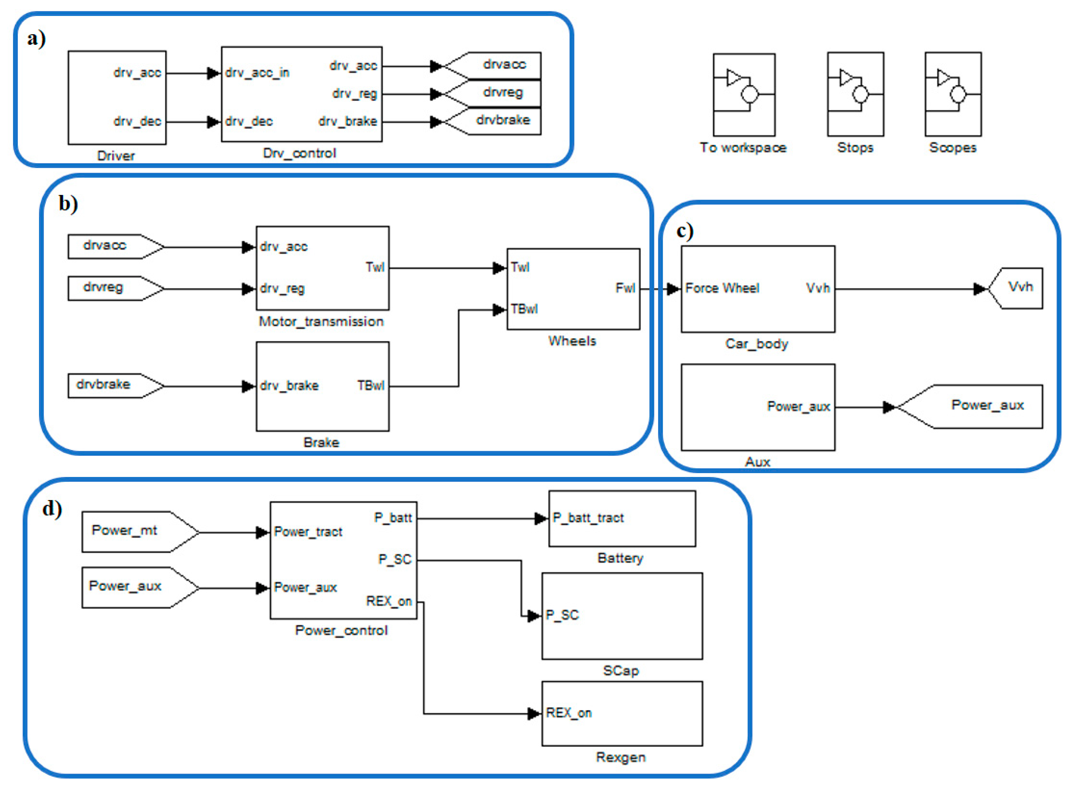
Figure 1. Layout of MATLAB-Simulink model: driver (a), powertrain (b), driveline (c), and energy management (d).
Machines 08 00051 g001
Figure 2. Look-up-tables for basic motor characteristics.
Machines 08 00051 g002
Figure 3. Brake-blending criteria: typical braking repartition in absence of regenerative braking capabilities (a) and brake blending for vehicles capable of regenerative braking capabilities on front axle (b).
Machines 08 00051 g003
Figure 4. Arithmetic mean of ERV over case studies per vehicle class and driving cycle.
Machines 08 00051 g004
Figure 5. ERV for all case studies in function of electricity consumption.
Machines 08 00051 g005
Figure 6. Arithmetic mean of IRV over case studies per vehicle class and driving cycle.
Machines 08 00051 g006
Figure 7. ERV for all case studies in function of main vehicle technical features: regression lines. Vehicle mass (M) (a), maximum power (Pmax) (b), and power-to-mass ratio (P/M) (c).
Machines 08 00051 g007
Figure 8. IRV for all case studies in function of vehicle mass: regression lines.
Machines 08 00051 g008
Figure 9. Break-Even Point (BEP) for sustainability case studies (Front Module (FM), Front Hood (FH), Front Door (FD), Crash Dashboard Beam (CDB), and Suspension Arm (SA)).
Machines 08 00051 g009
Figure 10. BEP in function of car mass for sustainability case studies FM, FH, and SA. Norwegian grid mix (a), average European grid mix (b), Polish grid mix (c).
Machines 08 00051 g010
Table 1. Energy Reduction Value (ERV) and Impact Reduction Value (IRV) for all vehicle case studies.
ERV (kWh/(100 km × 100 kg)IRV (kg CO2 eq/(100 km × 100 kg))
Vehicle ClassCase StudyNEDCWLTPALDCNO Grid MixEU28 Grid MixPL Grid Mix
NEDCWLTPALDCNEDCWLTPALDCNEDCWLTPALDC
A/B10.470.490.770.010.010.020.200.200.320.470.490.76
20.550.600.960.020.020.030.230.250.400.550.600.95
30.540.590.950.020.020.030.220.250.400.540.590.94
C40.520.570.890.020.020.030.220.240.370.520.570.88
50.520.570.900.020.020.030.220.240.370.520.570.89
60.530.580.910.020.020.030.220.240.380.530.580.90
70.570.610.990.020.020.030.240.250.410.570.610.98
D/E80.580.621.010.020.020.030.240.260.420.580.621.00
90.610.671.130.020.020.030.250.280.470.610.671.12
100.630.691.170.020.020.040.260.290.490.630.691.16
Notes: NO = Norwegian; EU28 = average European; PL = Polish; NEDC = New European Driving Cycle; WLTP = World Light Test Procedure; ALDC = All-Long Driving Cycle.
Table 2. Analysis of ERV and IRV per car class/driving cycle in terms of minimum and maximum value, size of range max–min, arithmetic mean, and standard deviation.
A/B ClassC ClassD/E ClassAll Classes
MinimumMaximumRange Max–MinArithmetic MeanMinimumMaximumRange Max–MinArithmetic MeanMinimumMaximumRange Max–MinArithmetic MeanMinimumMaximumRange Max–MinArithmetic MeanStandard Deviation
ERV (kWh/(100 km × 100 kg))NEDC0.470.550.080.520.520.570.050.540.580.630.050.610.470.630.160.550.05
WLTP0.490.600.110.560.570.610.040.580.620.690.070.660.490.690.200.600.06
ALDC0.770.960.190.890.890.990.100.921.011.170.161.100.771.170.400.970.12
IRV
(kg CO2 eq/(100 km × 100 kg))
NONEDC0.010.020.010.020.020.020.010.020.020.020.010.020.010.020.010.020.01
WLTP0.010.020.010.020.020.020.010.020.020.020.010.020.010.020.010.020.01
ALDC0.020.030.010.030.030.030.010.030.030.040.010.030.020.040.010.030.01
EU28NEDC0.200.230.030.220.220.240.020.220.240.260.020.250.200.260.070.230.02
WLTP0.200.250.050.230.240.250.020.240.260.290.030.270.200.290.080.250.02
ALDC0.320.400.080.370.370.410.040.380.420.490.070.460.320.490.170.400.05
PLNEDC0.470.550.080.520.520.570.050.530.580.630.050.600.470.630.160.550.05
WLTP0.490.600.110.560.570.610.040.580.620.690.070.660.490.690.200.590.06
ALDC0.760.950.190.890.880.980.100.921.001.160.161.100.761.160.400.960.12
Table 3. Modeling of ERV/IRV: equations of regression lines in function of mass.
ERV (kWh/(100 km × 100 kg))
NEDCWLTPALDC
ERVNEDC = 1.0 × 10⁻⁴ M + 0.3825ERVWLTP = 1.0 × 10⁻⁴ M + 0.3979ERVALDC = 3.0 × 10⁻⁴ M + 0.5363
IRV (kg CO2 eq/(100 km × 100 kg))
NEDCWLTPALDC
NOIRVNO_NEDC = 3.0 × 10⁻⁶ M + 0.0116IRVNO_WLTP = 4.0 × 10⁻⁶ M + 0.0121IRVNO_ALDC = 9.0 × 10⁻⁶ M + 0.0163
EU28IRVEU28_NEDC = 4.7 × 10⁻⁵ M + 0.1591IRVEU28_WLTP = 5.6 × 10⁻⁵ M + 0.1655IRVEU28_ALDC = 1.2 × 10⁻⁴ M + 0.2231
PLIRVPL_NEDC = 1.1 × 10⁻⁴ M + 0.3798IRVPL_WLTP = 1.3 × 10⁻⁴ M + 0.3951IRVPL_ALDC = 2.8 × 10⁻⁴ M + 0.5326