Abstract
The article presents the method of synthesis and analysis of the brushless motor with claw-poles. The motor is designed for the pilger mill drive for manufacturing seamless tubes. The peculiarity of the drive is that electric machines of this class for high power have not yet been used in world practice. In this regard, a very thorough analysis of the designed motor is required to remove technical risks in the manufacture of prototypes. For design of this motor the synthesis system and the analysis system were developed. The synthesis system is developed on the basis of nonlinear programming methods. For the analysis, it is proposed to use the program Ansys Electronics Desktop, which implements the finite element method. The peculiarity of using this program is the need to use large computer resources. Herewith, the calculation time of the main characteristics is often not acceptable for practical calculations and takes several hours. The authors propose a simplification of the computational model without significantly reducing the accuracy of the calculation. The brushless motor with claw-poles is replaced by a brushless motor with tangential magnets. The stator designs and the magnetic fluxes of the motors are the same. The effectiveness of such a replacement is shown in the real project. Calculation time with acceptable quality is reduced to a few minutes. This approach is recommended for the creation of design systems of other types of brushless machines. This scientific research was carried out for a real customer.
1. Introduction
Production of reliable large diameter pipes is an important task for enterprises that supply oil and gas complex. One of the variants for this solution can be the production of seamless pipes using pilgrim mill technology. Currently, there are about 100 such manufacturers in the world.
A pilgrim mill drive for producing seamless tubes runs in Chelyabinsk Pipe Rolling Plant (Russia) with 1928. As a drive motor for the mill, collector DC motor GM 900/100 company Siemens is used with the following main parameters: rated output power 2.75 MW, rated voltage 6 kV DC, rated speed 35 rpm. The motor rotates a flywheel with a diameter of 9 m with a large inertial mass of 120 tons.
Many years of operation of the electric motor led to its physical wear and obsolescence. The electric motor has a number of technical problems that threaten its further reliable operation. So, on the motor shaft from shock loads appeared micro cracks, which can lead to the destruction of the shaft. Currently, the question of replacing the existing motor with a more modern version is acute.
One of the variants for this replacement may be a brushless direct current motor (BLDCM) with permanent magnets. High-coercive permanent magnets create a powerful magnetic flux for improving energy parameters. However, using the motors of this type, which have large stator and rotor sizes, has one serious problem. Under the action of this flow there are large one-way magnetic forces between the stator and the rotor when assembling the motor. These efforts can be several tons. The rotor is attracted to the walls of the stator and assembly becomes almost impossible. The cost of special equipment for this assembly can exceed the cost of the motor by several times. For this reason, BLDCM of large diameter with permanent magnets practically do not applicate for these goals. Theoretically, it is possible to design tools for the assembly of such electric machines, but calculations show that the cost of these devices is ten times higher than the cost of the motor itself. The same problems arise when disassembling for routine maintenance and repair work.
The analysis of various designs of motors shows that the problem of assembly of electric motors of large dimensions with permanent magnets can be solved if you use a Claw-Pole Synchronous Machine (CPSM).
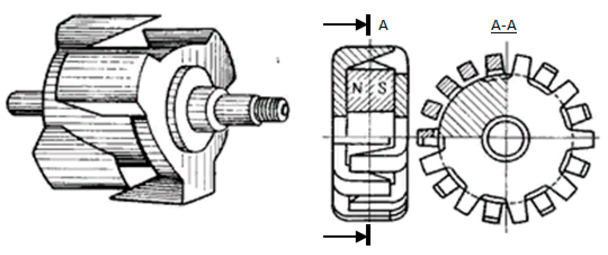
The design of CPSM inductor is shown in Figure 1.
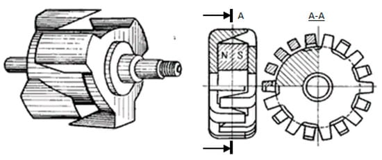
Figure 1.
The rotor form of the Claw-Pole Synchronous Machine with permanent magnet.
This design has a great advantage. The inductor can be assembled directly in the electric machine itself in parts by the following technology [1]:
- At the first stage, a shaft with a lower part of claws poles is inserted into the anchor. This part of the magnetic system at this stage of assembly is without magnets and will not be attracted to the walls of the anchor.
- At the second stage of assembly, a permanent magnet is mounted in the inductor. Depending on the size, it can be glued together in separate parts, or it can be mounted entirely.
- In the third stage, an upper part with claws poles is inserted into the inductor. Under the influence of electromagnetic forces of a permanent magnet, it must be drawn into the inductor.
- At the last final stage, the mounting of the bearing shield completes the assembly.
This technology of assembling a brushless motor with claw-poles does not require expensive equipment and special devices.
CPSM of low and medium power are well studied [2,3,4,5,6,7,8,9], but the design of machines for several megawatts with an outside diameter about 6 m is unique for engineering practice. It is necessary to take into account the shock load, transients in the anchor chain, scattering flows in the magnetic system, reactive moments when developing motor.
The development of a design system for such machines is an important scientific and engineering problem.
2. Formulation of the Problem
The CPSM has a complex magnetic system. The leakage magnetic flux has a large value. The leakage magnetic flux can be several times greater than the useful magnetic flux if the size of the magnetic system is not correctly determined. This is unacceptable for powerful motors with large dimensions [10,11,12,13,14,15,16].
To solve this problem, a design system was developed, which includes two parts: a system for the synthesis of optimal geometry and a system for the analysis of basic parameters and characteristics.
System of synthesis realizes optimization of the geometry of the BLDC motors using methods of nonlinear programming. It is described in detail in several articles [17,18,19,20,21,22,23].
It is based on a simplified technique using equivalent circuits. This approach makes it possible to apply optimization methods with a large number of iterations. However, this technique has a number of limitations and assumptions, in which the error of calculation of the main characteristics reaches 10–15%. This leads to technical risks in the manufacture of prototypes.
To reduce these risks, the system provides a stage of analysis. The system of analysis is based on well-tested CAD systems using the finite element method. So, we have used well-known CAD systems, but we have adapted them to solve our task.
One of the powerful tools for the analysis of electrical machines of different classes is the software package Ansys Electronics Desktop. It contains a large number of well-developed techniques of standard electric machines. CPSM is included in this list. The software package allows the user to make a preliminary analysis machine in RMxprt mode. This mode makes calculations based on the equivalent circuit method. To do this, it is enough to fill in table forms with the geometry, materials and parameters of the nominal mode. This greatly facilitates the analysis of the machine.
The software package allows you to transform the task into a 2D model. The program does this automatically when you select Create Maxwell 2D Design mode, but it is not possible to transform the CPSM into a 2D model because the motor geometry does not have a flat symmetry.
Practice shows that this greatly complicates the task of analysis. Test calculations showed that with the use of the program Ansys Electronics Desktop for 3D models in the mode of solving the dynamic Transient problem, the expectation of the results of the calculation of the main characteristics is from 8 to 15 h. This is not acceptable when it comes to debugging a model. At the same time, practice has shown that for a flat two-dimensional model, the solution of such a problem for a BLDC is from 20 to 40 min.
To resolve this contradiction, it was decided to replace the real design of the CPSM to BLDC with equivalent energy characteristics. BLDC has a flat symmetry for analysis. The closest analogue was a brushless machine of the BLDC type with a tangential excitation system. This machine has a similar anchor. The design of the inductor is different, but there are no electrical and magnetic losses in the inductor, all electromagnetic energy conversion processes occur in the anchor. If we choose the magnetic flux of the CPSM machine to be the same as for the machine with claw poles, we get almost a twin machine with the same of the magnetic and electrical losses, induced electromotive force in phase windings, electromagnetic torque and other basic parameters.
This principle was incorporated into the software package for the design of CPSM at the stage of analysis, which is described below.
3. Description of Software for the Design of CPSM
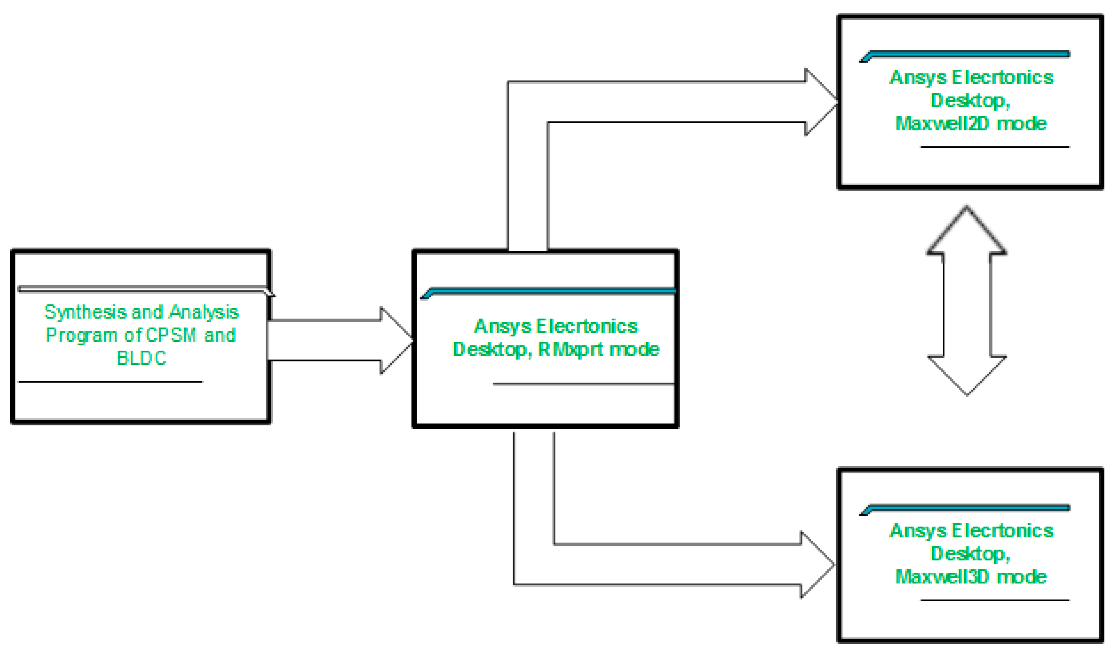
The logical scheme of designing CPSM is presented in Figure 2.
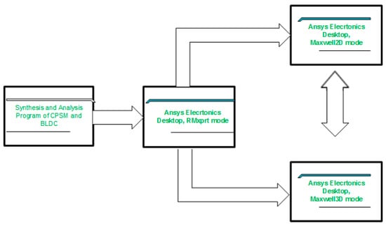
Figure 2.
Design scheme of a Claw-Pole Synchronous Machine (CPSM) design.
The task of synthesis is realized at the first stage. According to the technical task of the customer the problem of multi-level optimization is solved. The synthesis program was developed by the authors on the basis of the substitution scheme technique. This stage determines the optimal geometry of the motor and winding data.
At the second stage, the program Ansys Electronics Desktop mode RMxprt analyzes the optimal motor using a model CPSM, which is incorporated into the base of the program. The data are taken from the first stage of calculation. They are passed to the program using scripts. In this case, the correctness of the solution of the optimization problem by the main parameters is checked. They are: efficiency, flux in the gap, losses, torque, and EMF in phases. If there is a mismatch of some parameter, the optimization model is adjusted with the repetition of the cycle.
In the third stage, the real CPSM motor is replaced by a motor analog BLDC. To do this the data is transmitted from the model CPSM to the model BLDC with tangential magnets, while the internal diameter of the analog machine is selected so that the magnetic flux passing from the inductor to the anchor is equivalent. This provides the identity of all the characteristics of both machines. This stage is necessary to calculate the 2D magnetic field at the next step.
After this phase we use the capabilities of the Ansys Electronics Desktop. Software automatically transforms the task from mode to mode RMxprt Maxwell 2D Design. In this case, the analysis of the machine is based on the finite element method with the calculation of all parameters of the electromagnetic field. The calculation time at this stage is 20–40 min. If necessary, the model is adjusted.
At the final stage there is an analysis of the real 3D model of the motor with claw-poles CPSM. At this stage we already have all the optimal motor sizes and twin motor characteristics. We need to make sure for the last time that the problem is solved correctly. The model transforms from RMxprt mode to Maxwell 3D Design mode automatically. The analysis of the real model with the definition of all the necessary characteristics is defined on the finite element method. The analysis time is from 12 to 20 h, but this is acceptable since the problem is solved once.
Thus, the system implements the following design steps: specification for CPSM → geometry optimization in a specially designed program for the CPSM → check results in RMxprt mode for the CPSM → check results in RMxprt mode for BLDC motor → check results in Maxwell 2D design mode for BLDC motor → check results in Maxwell 3D design mode for the CPSM.
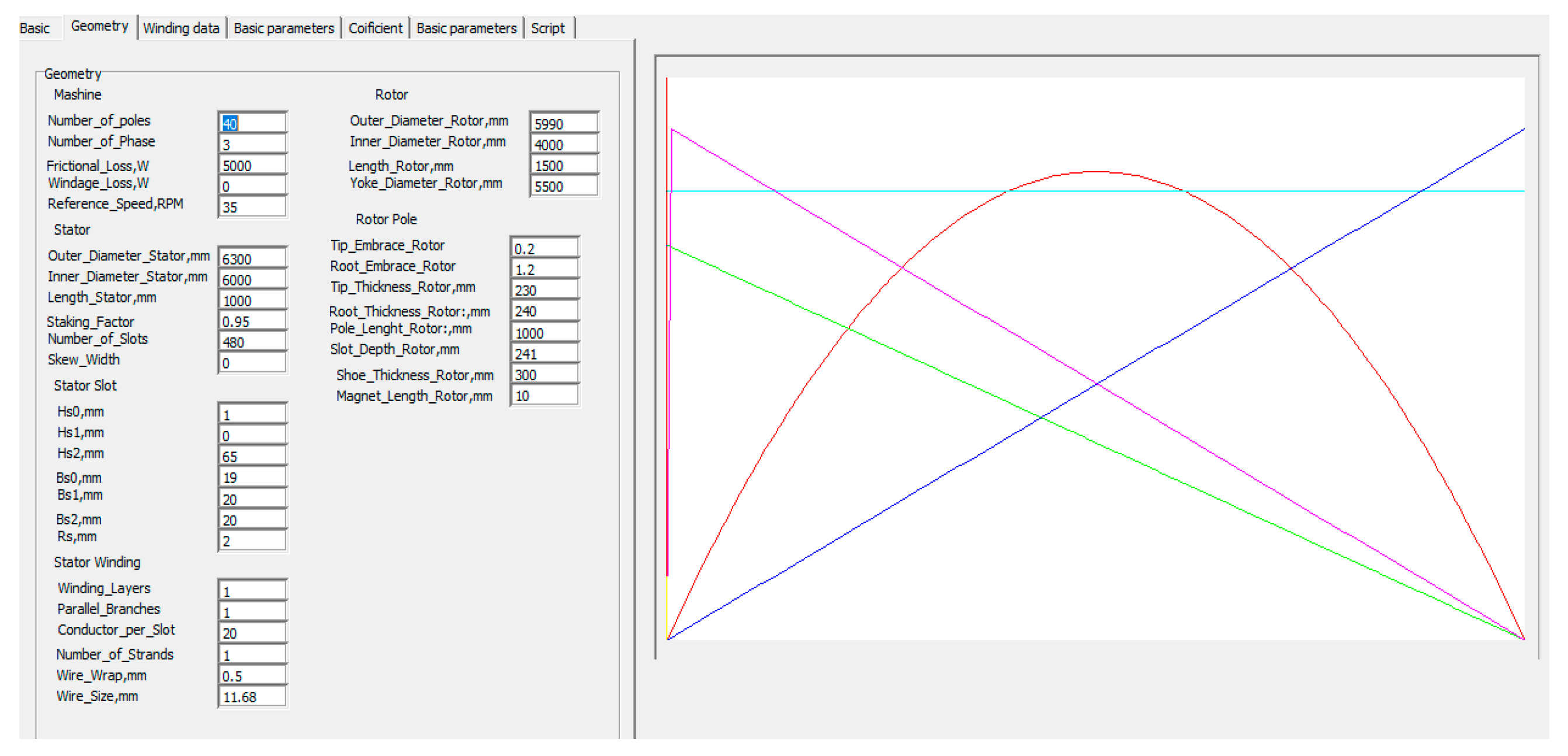
Below are the results of this design system for CPSM with the following parameters 2.5 MW, 600 V, 40 RPM to drive the pilger mill.
Figure 3 shows the results of the first stage (synthesis program). The program is written in the program language Delphi. It determines the optimal geometry of the machine according to the customer’s specifications.
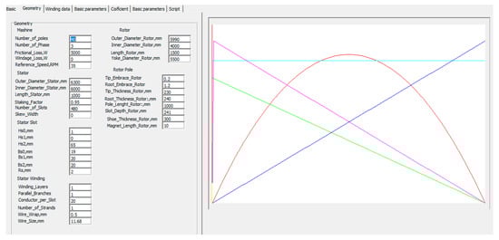
Figure 3.
The result of optimization for CPSM.
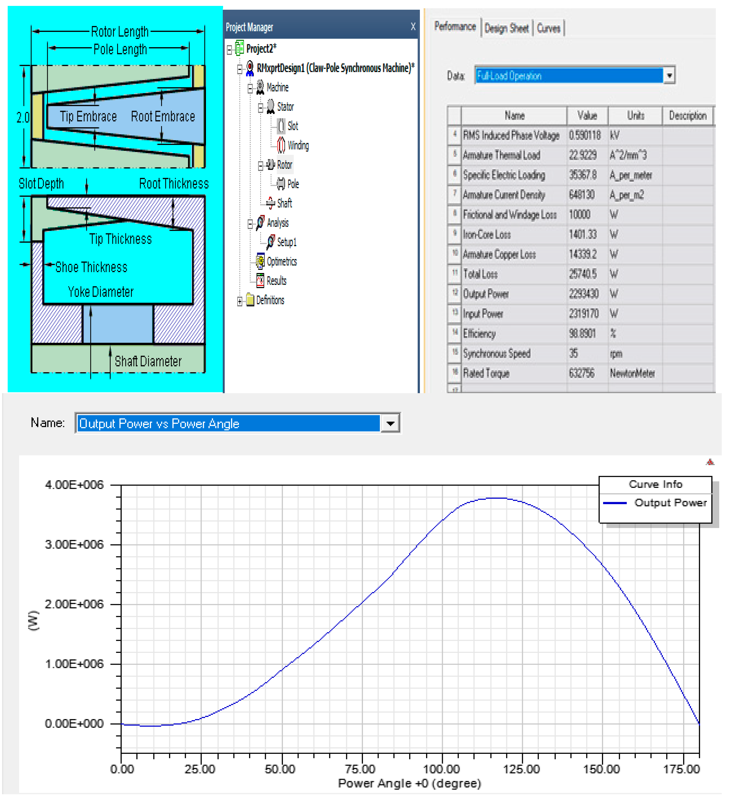
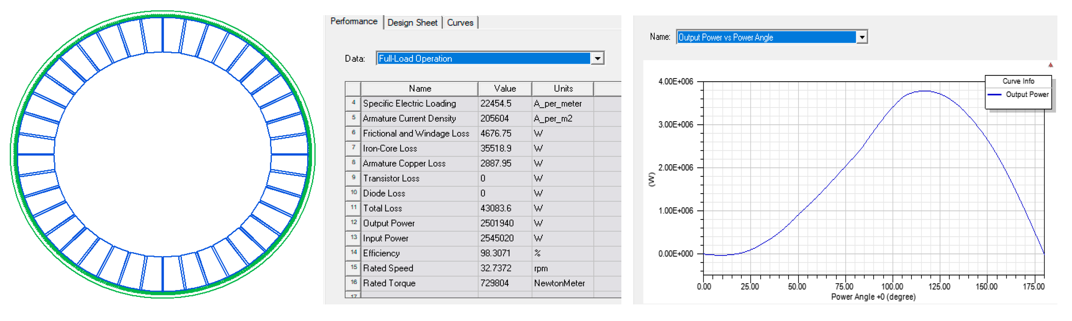
Next, the results of the calculation of the optimal geometry and winding data are transmitted to the program Ansys Electronics Desktop using a pre-developed script. In this program, the calculated parameters are checked in RMxprt mode. The ANSYS software package has a proven methodology for analyzing this type of machine (CPSM). The results of the work at this stage are presented in Figure 4.
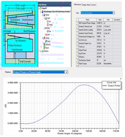
Figure 4.
The results of the CPSM in the mode RMxprt [1].
After that, in the RMxprt mode, the calculation of the BLDC with a tangential inductor begins. In this case, all the dimensions of the stator and the data of its winding are similar to the previous version. The magnetic flux of the analog machine with the internal diameter is selected to be equal to the magnetic flux of the CPSM.
The results of the analysis of this stage are shown in Figure 5.
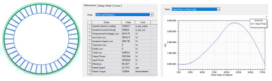
Figure 5.
Results of the calculation of the brushless direct current motor (BLDC) with tangential magnets in RMxprt mode.
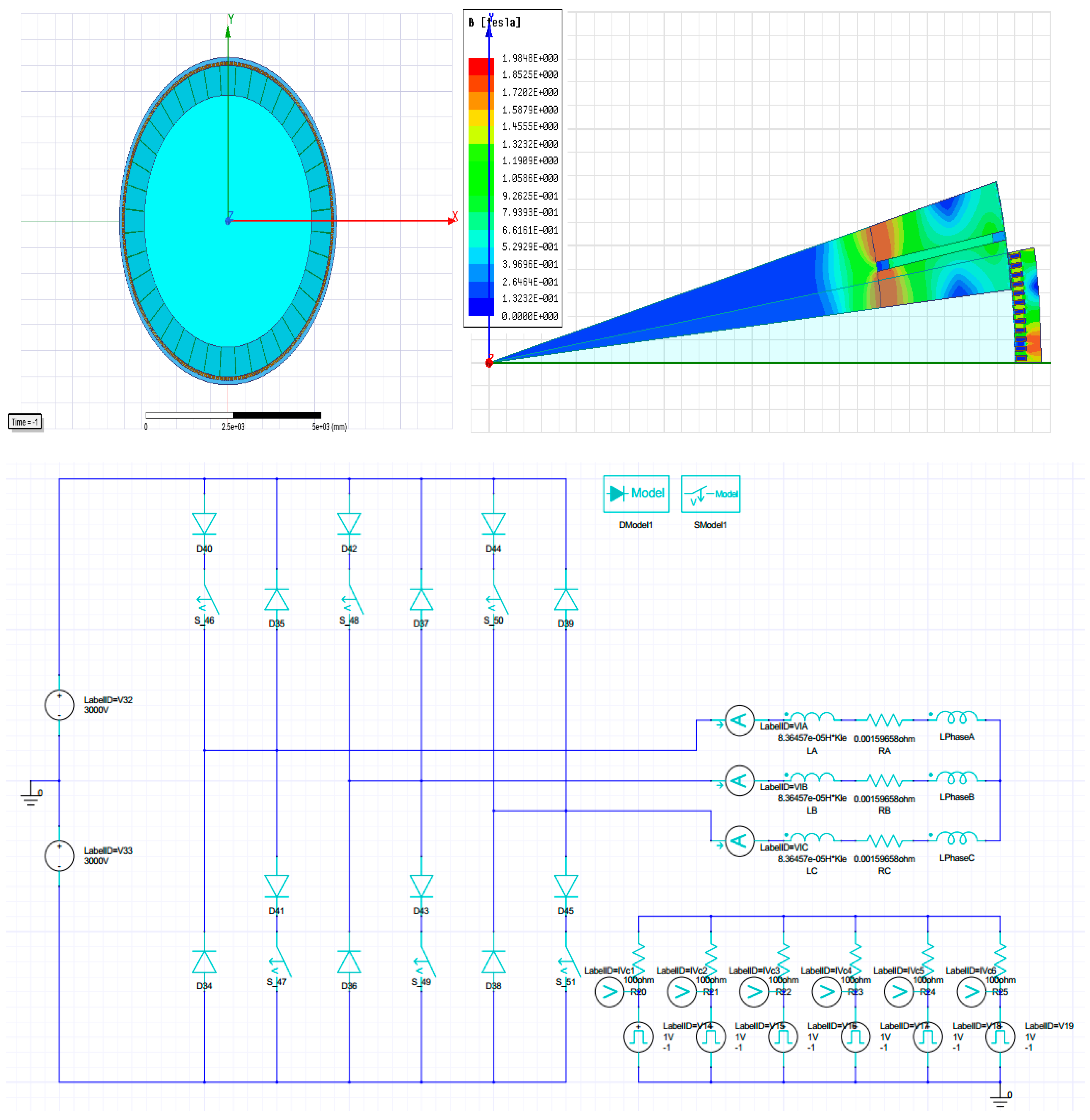
The next step in the analysis is to transform a BLDC into a flat two-dimensional model for finite element magnetic field analysis. This model is an exact copy of the CPSM. It has the same anchor and magnetic fluxes. Analysis of the characteristics is carried out using a simulator of the electronic circuit (Ansys Citrix Circuit). The results of the analysis of this stage are shown in Figure 6.
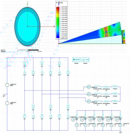
Figure 6.
Modeling of the BLDC motor with tangential magnets in a Maxwell 2D Design.
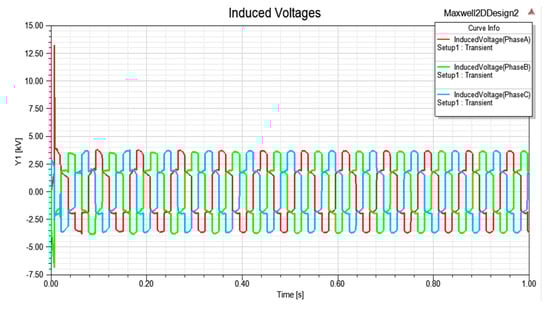
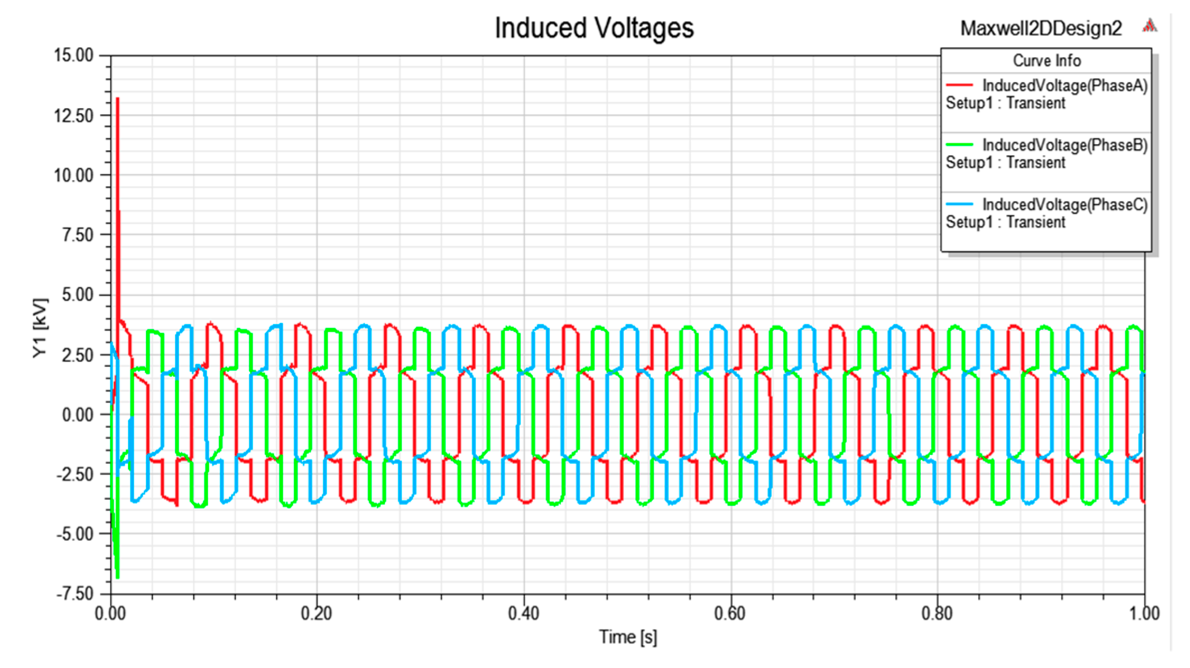
Figure 7.
Curves for electromotive force in phases.

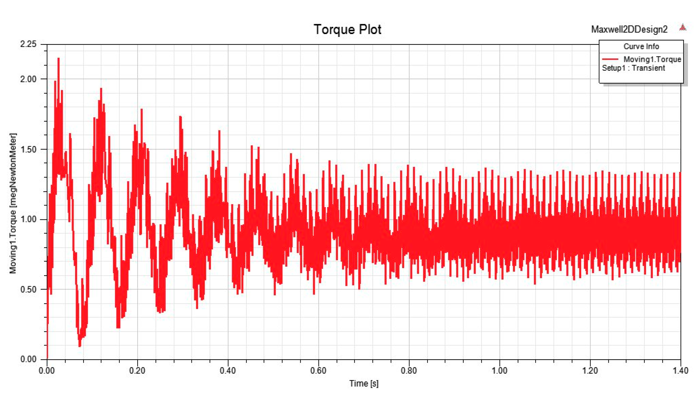
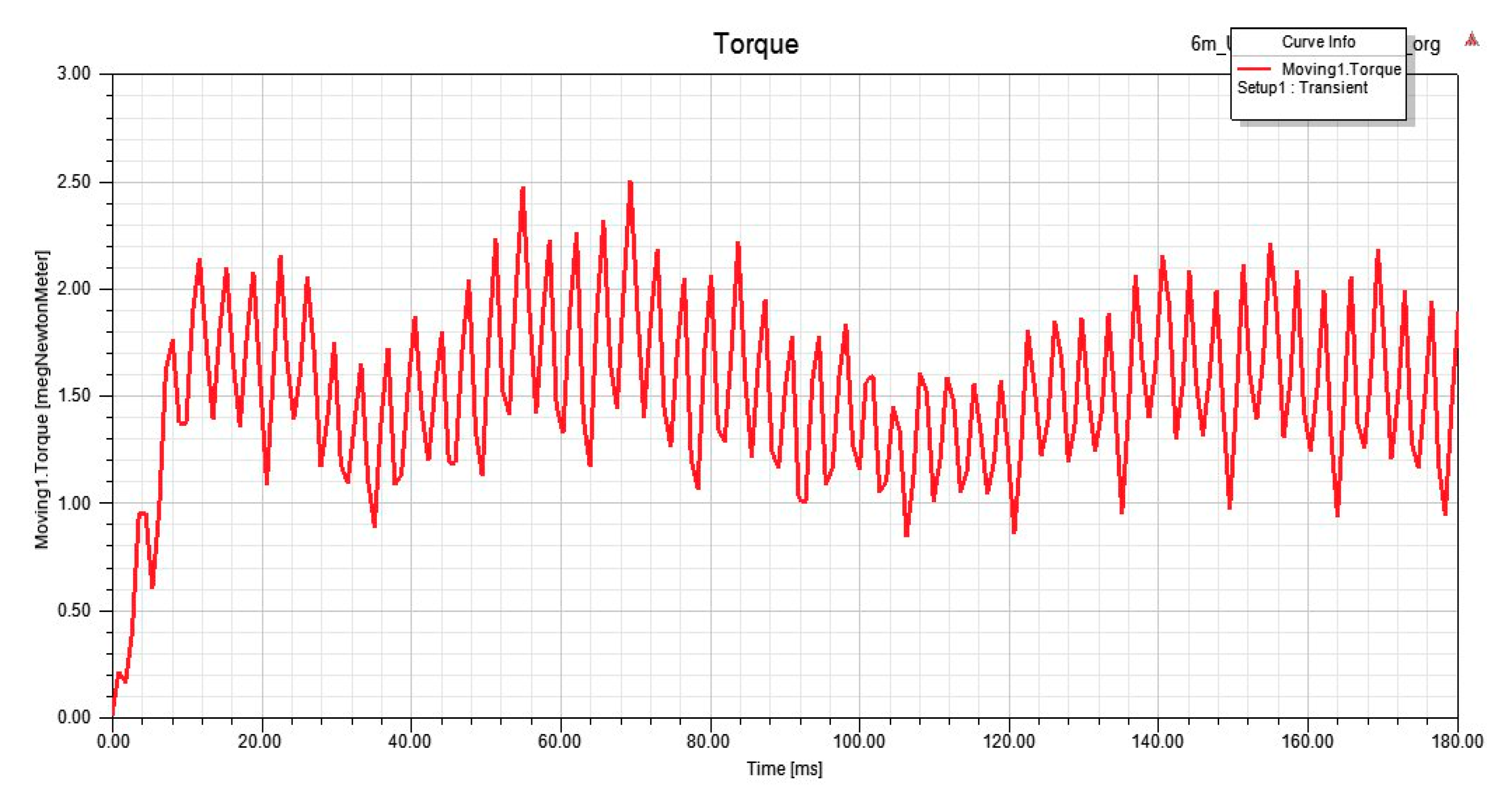
Figure 8.
Curves for electromagnetic torque.
At the last stage, from the RMxprt mode, the model of the CPSM automatically transforms into a three-dimensional model using the capabilities of the Ansys Electronics Desktop program to analyze the magnetic state and finally determine the main parameters and characteristics. The results of the analysis are shown in Figure 9 and Figure 10.
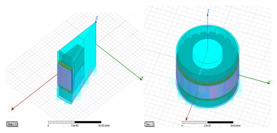
Figure 9.
Modeling of the CPSM in Maxwell 3D Design.

Figure 10.
The curve of the electromagnetic torque of the CPSM in Maxwell 3D Design.
According to the calculated curve of the CPSM, it is clear that the characteristics of the analyzed motor and the analog motor are close and within the calculation error, but the calculation of the main characteristics is from 8 to 15 h. Thus, synthesis and multistage analysis of electric machines with claw-poles is carried out.
4. Discussion
Currently, there are powerful CAD systems for the analysis of electrical machines, which have the ability to accurately calculate their parameters and characteristics.
It should be considered that these systems place very high demands on computers for performance and RAM. The engineer does not always have such opportunities. One of the problems is waiting for the calculation results for a long time for complex magnetic systems, if it is necessary to consider a large number of options. During the development of this design system, settlement work was almost stopped for this reason.
Practice shows that there is not always a need to complicate the computational model. Very often it is possible to analyze plane problems instead of three-dimensional ones with sufficient accuracy.
The presented design system is developed in this logical scheme. After the stage of synthesis, where the optimization was carried out on a simplified model for the equivalent circuit, the task proceeds to the next stage of the analysis in the Ansys software environment. Then, firstly, the plane problem of calculating the magnetic field is solved step by step, and then the three-dimensional problem of calculating the magnetic field. The maximum differences in the main parameters (efficiency, torque, speed, magnetic fluxes induced by EMF) are presented below:
- -
- the difference between the calculated parameters in the program Delphi and RMxprt for the CPSM ranged from 5 to 9%;
- -
- the difference between the results of RMxprt for CPSM and the results of RMxprt for the BLDC with tangential magnets was 3–5%;
- -
- the difference between the results of the design mode Maxwell 2D for the BLDC with tangential magnets and the results of Maxwell 3D design for a CPSM was 5–7%;
- -
- the difference between the results of the synthesis stage for the CPSM and the results of Maxwell 3D Design of the CPSM amounted to 9–12%.
This accuracy of calculation for such a complex magnetic system, such as CPSM, should be considered good.
5. Conclusions
Powerful machines with large dimensions and permanent magnets are not widely used in the world. This is due to the complex technology of stator and rotor assembly. Complex equipment is required to compensate for the large one-way magnetic attraction of the stator and rotor during assembly. The cost of this equipment can be several times higher than the cost of the motor itself. The article proposes a solution to this problem through the use of CPSM design. Motors with large sizes can be assembled without special equipment. This decision was applied in the development of the motor with rated output power 2.75 MW, rated voltage 6 kV DC, rated speed 35 rpm for the pilger mill.
For the design of this motor, a special design system was developed, which includes a synthesis system and an analysis system. The synthesis system determines the optimal motor geometry, and the analysis system tests all basic parameters and characteristics using the well-tested program Ansys Electronics Desktop based on finite element method. This program has one feature. It calculates the parameters very accurately, but it requires very large computer resources. The problem becomes much more complicated if you have to solve the three-dimensional task of calculating the magnetic field. The calculation time of one variant can be several hours. The task becomes practically unsolvable when you need to check several dozen variants for debugging.
The article proposes an original method of solving this problem. A real motor that has no flat symmetry is replaced by a twin motor that has flat symmetry. The task is greatly simplified. The calculation time is a few minutes. This model can be used to debug and refine all sizes. At the final design stage, the user can go back to the real three-dimensional model and spend a few hours for the testing calculation, but this is only once.
The conception has shown its effectiveness on a real project to develop a drive for pilger mill for the manufacture of seamless pipes. The authors believe that this approach can be effective in the development of design systems for other types of electrical machines and drivers [24,25,26,27,28,29,30,31,32].
Author Contributions
S.G. conceived the idea of this research; B.K. conducted the modeling work and wrote part of the paper under the supervision of S.G.; D.A. assisted in editing the paper.
Funding
This research was funded by South Ural State University.
Acknowledgments
The authors thank the leadership of the South Ural State University for the support and creation of conditions for this research work, as well as the management of the enterprise of Industrial partner (ChPRP), who took an active part in the project.
Conflicts of Interest
The authors declare no conflict of interest.
References
- Gandzha, S.; Kosimov, B.; Aminov, D. Selecting optimal design of electric motor of pilgrim mill drive for manufacturing techniques seamless pipe. In Proceedings of the ICIEAM 2019 International Conference on Industrial Engineering, Applications and Manufacturing, Sochi, Russia, 25–29 March 2019. [Google Scholar]
- Omri, R.; Ibala, A.; Masmoudi, A. Characterization on the no-and on-load operations of an improved claw pole machine. In Proceedings of the 2018 EVER 13th International Conference on Ecological Vehicles and Renewable Energies, Monte-Carlo, Monaco, 10–12 April 2018; pp. 1–8. [Google Scholar]
- Njeh, A.; Trabelsi, H. New design of the claw-pole transverse flux permanent magnet machine. In Proceedings of the 2018 15th International Multi-Conference on Systems, Signals and Devices, Hammamet, Tunisia, 19–22 March 2018; pp. 1311–1316. [Google Scholar]
- Bai, H.; Pekarek, S.D.; Tichenor, J.; Krefta, R.J.; Shields, S.J. Analytical derivation of a coupled-circuit model of a claw-pole alternator with concentrated stator windings. IEEE Trans. Energy Convers. 2002, 17, 32–38. [Google Scholar] [CrossRef]
- Kopylov, I.P. Elektricheskiye Mashiny [Electrical Machines]; Moscow High School: Moscow, ID, USA, 2006; p. 607. (In Russian) [Google Scholar]
- Vol’dek, A.I. Elektricheskiye Mashiny [Electrical Machines]; Leningrad, Energy: St Petersburg, Russia, 1978; p. 832. (In Russian) [Google Scholar]
- Kostenko, M.P.; Piotrovskiy, L.M. Elektricheskiye Mashiny, Mashiny Postoyannogo Toka. Transformatory [Electrical machines, DC Machines. Transformers]; Leningrad: Moskow, Russia, 1972; p. 544. (In Russian) [Google Scholar]
- Cristian, B.; Constantin, O.; Chiver, O.; Mircea, H.; Adina, P.V. The advantages of numerical analysis for claw pole alternator. In Proceedings of the EPE 2014 International Conference and Exposition on Electrical and Power Engineering, Iasi, Romania, 16–18 October 2014; pp. 353–357. [Google Scholar]
- Jurca, F.; Martis, C. Claw-Pole generator parameters and steady-state performances analysis. Int. Rev. Model. Simul. 2013, 6, 41–48. [Google Scholar]
- Rebhi, R.; Ibala, A.; Masmoudi, A. MEC-based sizing of a hybrid-excited claw pole alternator. IEEE Trans. Ind. Appl. 2015, 51, 211–223. [Google Scholar] [CrossRef]
- Gandzha, S.; Aminov, D.; Kosimov, B. Development of engineering method for calculation of magnetic systems for brushless motors based on finite element method. In Proceedings of the ICIEAM 2019 International Conference on Industrial Engineering, Applications and Manufacturing, Sochi, Russia, 25–29 March 2019. [Google Scholar]
- Zhang, F.-G.; Bai, H.-J.; Liu, Y. Leakage magnetic calculation on claw pole machine with outer permanent magnet rotor. Dianji yu Kongzhi Xuebao/Electr. Mach. Control 2009, 13, 548–552. [Google Scholar]
- Desanti, A.F.; Sidharta, I.; Erwantono, H.; Suryoatmojo, H.; Wahyudi, M. Design of Performance and Parameter Measurement System for Brushless Direct Current (BLDC) Motor. In Proceedings of the ISITIA 2018 International Seminar on Intelligent Technology and Its Application, Bali, Indonesia, 30–31 August 2018; pp. 175–179. [Google Scholar]
- Park, H.-S.; Park, S.-W.; Kim, D.-Y.; Kim, J.-M. Hybrid phase excitation method for improving efficiency of 7-phase BLDC motors for ship propulsion systems. J. Power Electron. 2019, 19, 761–770. [Google Scholar]
- Gandzha, S.; Aminov, D.; Kosimov, B. Design of Brushless Electric Machine with Axial Magnetic Flux Based on the Use of Nomograms. In Proceedings of the 2018 International Ural Conference on Green Energy, UralCon, Moscow, Russia, 15–18 May 2018; pp. 282–287. [Google Scholar]
- Swapna, S.; Siddappa Naidu, K. Speed characteristics of brushless dc motor using adaptive neuro fuzzy PID controller under different load condition. Int. J. Recent Technol. Eng. 2019, 7, 472–479. [Google Scholar]
- Gandzha, S.A.; Kiessh, I.E. Varible speed power. Procedia Eng. 2015, 129, 731–735. [Google Scholar] [CrossRef]
- Gandzha, S.; Kiessh, I.; Aminov, D. Development of engineering technique for calculating magnet systems with permanent magnets. In Proceedings of the International Conference on Industrial Engineering, Applications and Manufacturing (ICIEAM), Moscow, Russia, 15–18 May 2018. [Google Scholar] [CrossRef]
- Gandzha, S. The application of the double-fed alternator for the solving of the wind power problems. In Proceedings of the International Multidisciplinary Scientific GeoConference Surveying Geology and Mining Ecology Management, SGEM, Vienna, Austria, 2–5 November 2016; Volume 3, pp. 321–328. [Google Scholar]
- Gandzha, S.A. Proposals for the design of high-speed electric machines. In Proceedings of the International Conference on Industrial Engineering, ICIE 2016 9th Asia-Oceania Symposium on Fire Science and Technology, Chelyabinsk, Russia, 19–20 May 2016. [Google Scholar]
- Lai, C.-K.; Tsao, Y.-T.; Tsai, C.-C. Modeling, Analysis, and Realization of Permanent Magnet Synchronous Motor Current Vector Control by MATLAB/Simulink and FPGA. Machines 2017, 5, 26. [Google Scholar] [CrossRef]
- Lee, J.S. Stability Analysis of Deadbeat-Direct Torque and Flux Control for Permanent Magnet Synchronous Motor Drives with Respect to Parameter Variations. Energies 2018, 11, 2027. [Google Scholar] [CrossRef]
- Wang, W.; Wang, W. Compensation for Inverter Nonlinearity in Permanent Magnet Synchronous Motor Drive and Effect on Torsional Vibration of Electric Vehicle Driveline. Energies 2018, 11, 2542. [Google Scholar] [CrossRef]
- Jung, T.-U.; Jang, J.-H.; Park, C.-S. A Back-EMF Estimation Error Compensation Method for Accurate Rotor Position Estimation of Surface Mounted Permanent Magnet Synchronous Motors. Energies 2017, 10, 1160. [Google Scholar] [CrossRef]
- Qian, J.; Ji, C.; Pan, N.; Wu, J. Improved Sliding Mode Control for Permanent Magnet Synchronous Motor Speed Regulation System. Appl. Sci. 2018, 8, 2491. [Google Scholar] [CrossRef]
- Gandzha, S.; Kiessh, I. Selection of winding commutation for axial gap machines with any phases. In Proceedings of the 2018 ICIEAM International Conference on Industrial Engineering, Applications and Manufacturing, Moscow, Russia, 15–18 May 2018. [Google Scholar]
- Gandzha, S.; Sogrin, A.; Martyanov, A.; Kiessh, I. The design of the low-speed brushless motor for the winch which operates in see-water. In Proceedings of the SGEM International Multidisciplinary Scientific GeoConference Surveying Geology and Mining Ecology Management, Vienna, Austria, 27–29 November 2017; pp. 783–790. [Google Scholar]
- Gandzha, S.; Aminov, D.; Kiessh, I.; Kosimov, B. Application of Digital Twins Technology for Analysis of Brushless Electric Machines with Axial Magnetic Flux. In Proceedings of the GloSIC 2018 Global Smart Industry Conference, Chelyabinsk, Russia, 13–15 November 2018. [Google Scholar]
- Gandzha, S.; Kiessh, I. The high-speed axial gap electric alternator is the best solution for a gas turbine motor. In Proceedings of the SGEM International Multidisciplinary Scientific GeoConference Surveying Geology and Mining Ecology Management, Vienna, Austria, 27–29 November 2017; Volume 17, pp. 791–796. [Google Scholar]
- Gandzha, S.A.; Sogrin, A.I.; Kiessh, I.E. The Comparative Analysis of Permanent Magnet Electric Machines with Integer and Fractional Number of Slots per Pole and Phase. Chelyabinsk, Russia. Procedia Eng. 2015, 129, 408–414. [Google Scholar] [CrossRef]
- Gandzha, S.A.; Kiessh, I.E. Application brushless machines with combine excitation for a small and medium power windmills. Procedia Eng. 2015, 129, 191–194. [Google Scholar]
- Zheng, P.; Wu, Q.; Zhao, J.; Bai, J.; Zhao, Q. Performance analysis and simulation of a novel brushless double rotor machine for power-split HEV Applications. Energies 2012, 5, 119–137. [Google Scholar] [CrossRef]

© 2019 by the authors. Licensee MDPI, Basel, Switzerland. This article is an open access article distributed under the terms and conditions of the Creative Commons Attribution (CC BY) license (http://creativecommons.org/licenses/by/4.0/).