Article

Dynamic Torque Limitation Principle in the Main Line of a Mill Stand: Explanation and Rationale for Use

Department of Mechatronics and Automation, South Ural State University (National Research University), Chelyabinsk 454080, Russia
*
Author to whom correspondence should be addressed.
Machines 2019, 7(4), 76; https://doi.org/10.3390/machines7040076
Submission received: 22 October 2019 / Revised: 4 December 2019 / Accepted: 5 December 2019 / Published: 6 December 2019
(This article belongs to the Special Issue Selected Papers from the ICIEAM 2019 Conference)

Abstract

:
This paper substantiates why it is necessary to limit the dynamic loads in stand shafts when closing angular gaps. The paper is a feasibility study of a concept developed specifically to limit each of the factors that affect amplitude of the dynamic torque; limitations applied are determined on a case-by-case basis. The research team studied the components of elastic torque in a dual-mass electromechanical system of Mill 5000 caused by vibrations arising from the elasticity of transmission as well as from the vibrations caused by elastic collision itself. It is shown that the lowest possible pre-acceleration is necessary for decreasing the dynamic coefficient at a near-nominal load torque. A principle of limiting dynamic loads when closing an angular gap is proposed, which implies collecting tachograms of an electric drive subjected to positive or negative acceleration before and after the fed metal is captured. The research team has developed drive control principles to implement this approach. The recommendation is to upgrade the electric drives of the reversing stand in Mill 5000.

1. Introduction

One of the most important applied research issues, resolving which will reduce the risk of accidents in the roll lines of a mill, is to limit the shock loads occurring when rolls capture the fed metal. Unacceptable loads are mainly caused by the difference in the peripheral speed of rolls and the speed of workpiece being fed into a stand (horizontal force loading); or by the closure of angular gap (play) in spindle connections when metal is captured (torque loading) [1].
Multiple papers have covered limiting the horizontal component of dynamic torque, including [2,3,4,5,6,7]. Most commonly proposed solutions are to strictly adhere to the metal feed rate on the conveyor as well as to more accurately locate the bars by using a bar tracker.
Limiting the effects of angular play is relevant for almost all shock-sustaining rolling mills, including plate Mill 5000 of Magnitogorsk Iron and Steel Works (MMK), PJSC. In recent decades, it has become especially relevant as MMK has expanded its assortment and begun to roll difficult-to-form steel required for manufacturing large-diameter pipes [8,9,10]. This leads to higher loads on electromechanical systems employed rolling mill stands, whether running in steady state or not.
Mill 5000 can produce rolled steel complying with a wide range of Russian and international standards. The mil is equipped to roll and finish sheets of the following specifications (applicable at 20 °C): ultimate strength of 1200 MPa at max; yield point of 1000 MPa at max for 40 mm sheets, 750 MPa for 41–50 mm sheets. Within a small variation of the chemical composition, mechanical characteristics may vary by no more than 90 N/mm2 within a batch or 50 N/mm2 within a plate [11].
Gaps are mainly created by the spindle connections, primarily on the side of the work roll. Proximity of these connections to the stand, their inclined position, high temperature, ingress of mill scale and water cause increased wear of roll spindles and bronze inserts.
The reversing stand of Mill 5000 contains slipper type spindles, see Figure 1a for the design. The roll is immediately connected to the spindle with a specially designed head fixed on the working shaft. The same head is mounted on the side of the motor. The spindle shaft is slotted to compensate for the axial displacement occurring when the rolls are displaced by the continuous variable crown (CVCplus) system [12]. The spindle bearing is located near the middle of the shaft. Each spindle is individually counterbalanced with a hydraulic cylinder, levers, and coupling rods vertically and (if using CVCplus) horizontally [13,14].
Figure 1b shows why shock occurs when closing the play δ [15]. Rotating spindle heads collide regularly with the roll extension. These collisions occur in the inserts and bearing segments constituting the universal joint hinges. As a result, oscillatory processes emerge in the gears. This mechanism relates to the configuration of the play, which is always found in spindle connections. Torque usually peaks at the first oscillation peak.
Numerous papers cover this process as observed in non-steady state, while monographs [16,17] detail upon the electrotechnical systems in rolling mills. Reference [18] graded the known methods of reducing dynamic loads occurring when angular gaps are closed. In particular, it enumerates the following methods:
-
optimizing the functions to control the electric drive;
-
reducing the rigidity of mechanical gears;
-
monitoring the elastic torque by special software, etc.
Analysis shows that algorithmizing special electric drive controls is the most affordable approach. However, the existing technical solutions have not been adopted by the industry on a large scale. The current literature contains no data on implementing such controls in plate rolling mills. This is why limiting the dynamic loads in electromechanical roll systems is a relevant research issue; find studies of Mill 5000 below.

2. Statement of Problem

References [19,20] describe limiting the dynamic torque by capturing the fed metal when the electric drive is accelerated (pre-acceleration) to ensure preliminary angular play closure. Figure 2 shows a simplified functional chart of the electric drives powering the reversing-stand rolls in Mill 5000, which uses this principle [21]. Information from the current metal tracking system for conveyor tables is used to find when to trigger pre-acceleration. The value of such pre-acceleration is configured using an additional power-up sensor; its output signal is mixed with that of the interpolator. The pre-acceleration time must suffice for complete closure of the play. The additional acceleration rate is configured experimentally; for the electric drive under consideration it is 0.22 m/s2. The firmware of the stand controller uses an algorithm based on this chart.
References [22,23] prove that this system does reduce the dynamic loads on electric engines and mechanical equipment provided accurate pre-acceleration timing and value. In most cases, the system attains 1.3 to 1.5 times lower amplitude of dynamic torque; the dynamic drop in speed is reduced similarly.
However, such a positive result in not always the case in practice, because unacceptable dynamic loads on the shaft lines of horizontal rolls are caused not only by the dynamic impact attributable to the angular play closure, but also by damped torque oscillations. Their amplitude depends on the elastic properties of a shaft line, whereas the degree of dampening is determined by dissipative forces (friction, heating, etc.). As a proof, Figure 3 shows torque waveforms for the shafts of the top and bottom stand spindles, Mill 5000, as well as the waveforms of their torsional oscillations [24]. These were obtained using a MANNER TG28TE elastic deformation measurement system installed by MANNER (city, Germany). A waveform analysis can conclude that:
(1)
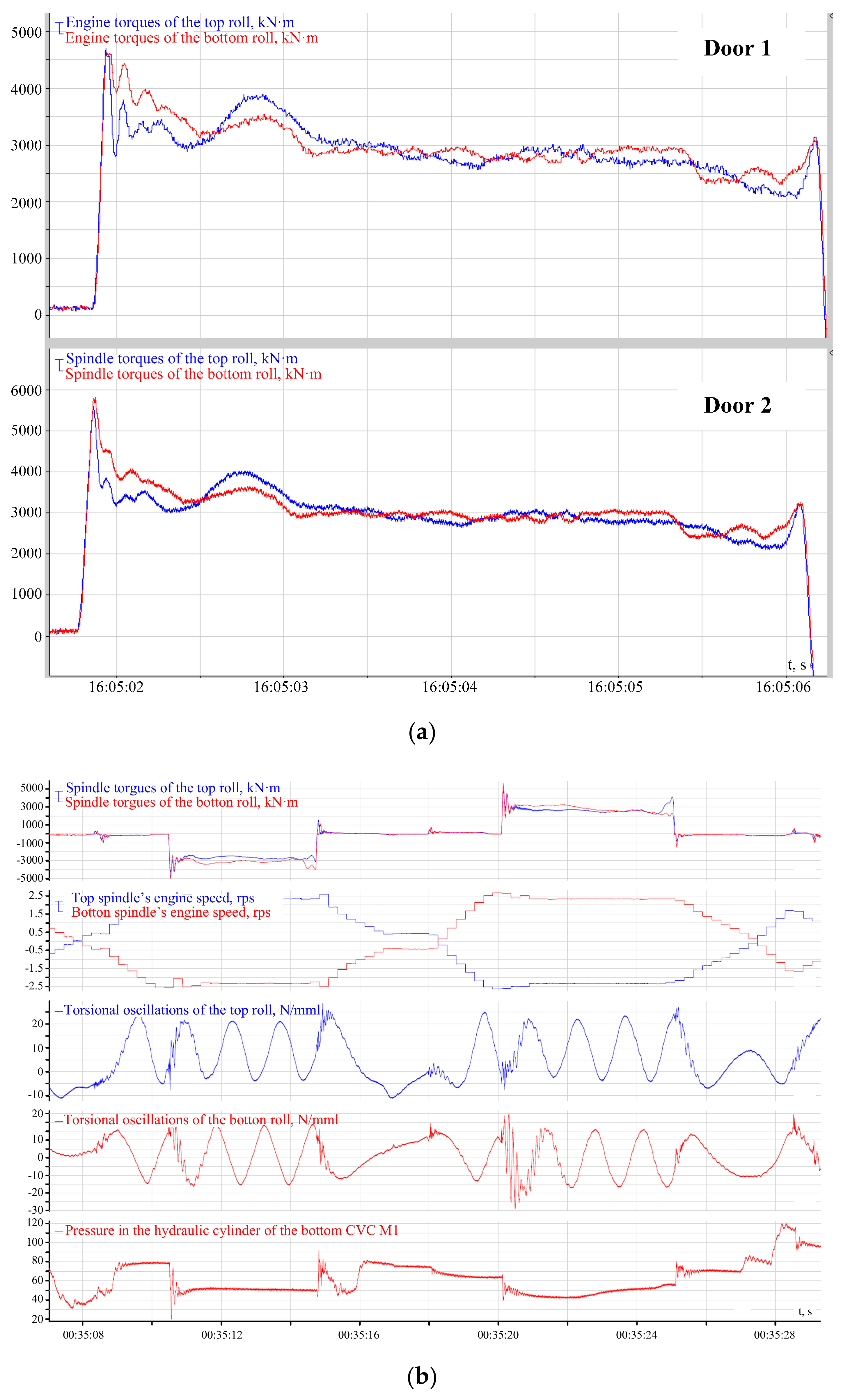
Impact torque amplitude at the moment of capture (Figure 3a, door 2) is nearly double the configured rolling torque (up to 5.8 MN·m vs. 3 MN·m).
(2)
Torsional oscillations overlaying a sine wave caused by shaft rotation feature a high amplitude, especially in case of the bottom spindle (Figure 3b).
(3)
Engine and spindle torques change identically with slight differences in the maximum torque and the time attain it. As mechanical and electrical systems are inertial, the maximum shaft torque (Figure 3a, door 2) is attained earlier than that of the engine (door 1). The difference is 0.1–0.15 s.
(4)
As the elastic shaft torque and electromagnetic engine torque have identical dynamic processes, it is sufficient to use the latter as the main controlled parameter; the feasibility of doing so is proven in [25,26].
The provided waveforms confirm that the dynamic torque amplitude and shock loading depend on the elastic properties of a mechanical gear in a dual-mass system. Damped torque oscillations are seen in these waveforms, and maximum values are observed at the first peak after metal capture. As demonstrated below, the amplitude of oscillatory processes may be considerably higher than the maximum part of the torque caused directly by shock play closure.
Analysis of these and other waveforms demonstrates that pre-closing the angular play by means of accelerated capture is not sufficient to reduce the elastic torque of the shaft. It is necessary to develop methods of control to ensure sustainable limitation of the dynamic torque. These methods must be based on a general (conceptual) approach, according whereto each factor determining dynamic torque amplitude must be limited on an individual basis. To do that, it is reasonable to analyze components of the elastic torque that the shaft is exposed to when the play is closed.

3. Analysis of Elastic Torque Components when Choosing Play

According to the scheme in Figure 1a, the drive of Mill 5000 stand rolls is a custom one. A roll line does not have any elements, the weight whereof is comparable to weights of rotating parts of an engine and a roll. That is why a “traditional” dual-mass system scheme provided in Figure 4 is used to evaluate the impact of gear play on dynamic loads affecting electric drives [17]. The model does not take into account dissipative forces, because they do not affect the first torque peak amplitude on impact.
Analysis is performed based on the following conditions: prior to the acceleration, gear play δ is completely open, electric drive is accelerated according to the linear law with constant angular acceleration ε0 at constant engine torque M1. When the acceleration begins and there is no mechanical connection between inertial masses (the second mass is motionless; ω2 = 0), the engine evenly accelerates to the initial speed:
ω init = 2 ε 0 δ
When the play is chosen, an elastic impact occurs in the gear, which results in the transformation of the kinetic energy stored in the first mass to the elastic mode energy. Ignoring the dissipative forces, the motion of the electric drive in this mode is calculated as follows:
M 1 M 12 = J 1 d ω 1 d t M 12 M c = J 2 d ω 2 d t
Solving a system for M12, we obtained the following differential equation:
1 ω 12 d 2 M 12 d t 2 + M 12 = J 2 ε a v + M c
where ε a v = M 1 M 12 J 1 + J 2 is an average acceleration after the play is chosen; ω 12 = c 12 J 1 + J 2 J 1 J 2 is a natural frequency of oscillations of an elastic dual-mass system.
Solution of this equation at zero initial conditions helps to decompose the elastic torque (divide it into components):
M 12 = M 12 c + c 12 ω init ω 12 sin ( ω 12 t ) M 12 c cos ( ω 12 t )
where M 12 c = J 2 ε a v + M c is the mean elastic torque.
As for the electric drive used in Mill 5000 stands (Figure 2) the features a double-loop subordinate control system with a power-up sensor, we may assume that εav = ε0, i.e., the average acceleration after an elastic impact is the same as prior thereto.
Equation (4) has two sinusoidal components:
M 12 y = M 12 c cos ( ω 12 t )
M 12 δ = c 12 ω init ω 12 sin ( ω 12 t )
Component (5) is associated with the oscillations occurring due to gear elasticity, where component (6)—oscillations appearing as a direct result of an elastic impact.
Mechanical oscillations increase torque of the load on gears. The dynamic amplification factor may be used to evaluate exceedance of the dynamic torque [15,16]:
k D = M 12 max M 12 c = 1 + 1 + c 12 2 2 ε 0 δ ω 12 2 M 12 c 2
Therefore, the impact-caused component of the dynamic amplification factor depends on the angular play δ, other things being equal. However, it is low (0.017–0.17 rad, and its square root is even lower), which is why the play affects the dynamic torque only insignificantly. The same conclusion may be made on the basis of results of the analysis of component change graphs plotted using Equations (5) and (6) (see Figure 5 and the notes on the graphs below).
According to Equations (4) and (7), the dynamic amplification factor depends on four factors: stiffness of the elastic coupling c12, natural frequency of elastic oscillations ω12, initial engine speed at the moment of play choice ωinit, and average elastic torque M12c determined by the load torque. It ought to be mentioned that the first two parameters are basically constants, as an electric drive does not affect them in any way. The study of how the two remaining parameters affect the dynamic amplification factor is of interest. It ought to be mentioned that the initial speed at the moment of play choice is a function of two other parameters—initial acceleration of the electric drive and angular play in the gear. See the structural layout of a model of a dual-mass system in Figure 4b. See the equipment parameters for Mill 5000 required to plot this layout in the Table 1.
The structure analysis was conducted in the MS Excel Visual Basic for Applications (VBA) software environment. This is a simplified version of Visual Basic, built into a number of the Microsoft Office products. It allows writing codes in a specific document file.
For qualitative evaluation of the processes taking place in an electric drive after an elastic impact see Figure 5 with an M12 torque change graph based on Equation (4), temporary dependencies of the separate components calculated using Equations (5) and (6), and an Mc static load torque graph. They correspond to the following conditions: εav = ε0 = 1.6 rad/s2, Mc = 1,910,000 N∙m (nominal engine torque), gear play 10° (overestimated value for qualitative evaluation of processes). We can see that component M12δ caused by an elastic impact has a significantly lower amplitude than component M12y caused by elastic oscillations in the gear. Amplitude ratio M12δmax/M12ymax = 0.21; M12δ torque amplitude features a non-linear dependence on the play and increases insignificantly if the play becomes wider.
Therefore, we may conclude that gear play impacts the maximum torque less considerably than elastic properties of the shaft line. For instance, when the play changes from 1° to 10°, the M12δmax/M12ymax ratio varies from 0.067 to 0.21. Therefore, the second component has an amplitude that is 4.7–15 times higher than that of the first component. It ought to be mentioned that this conclusion covers the initial moment of time immediately after capture, because in a real system dissipative forces result in unequal dampening of oscillations. This issue requires further studies using an electric drive model, which is why it is not considered here.
If ε 0 < < ε a v , i.e., when the play is closed by means of pre-acceleration with low initial acceleration, component M12δ may be somewhat reduced. For instance, if ε0 = 0.16 rad/s2 and maximum play is 10°, the M12δmax/M12ymax ratio = 0.067, i.e., 3 times lower than when accelerations are the same.
The following conclusions were reached as a result of analysis of elastic torque at capture without pre-acceleration:
The first component is determined only by average elastic torque M12c; it basically determines the first maximum of the dynamic torque in the shaft. This torque may be divided into a constant component and a variable component M 12 c = J 2 ε a v + M c . It may be compensated by negative dynamic torque, i.e., by means of negative acceleration after capture.
The second component is determined by the initial speed at the time of capture, stiffness of the elastic coupling c12 and moments of inertia of the dual-mass system. Initial speed ω init = 2 ε 0 δ is determined by angle δ. That is why when the play is chosen and δ = 0, this component equals zero.
Therefore, in order to reduce the dynamic torque, the following two conditions have to be met:
-
ensure play closure by means of pre-acceleration to minimize the second component;
-
decelerate the electric drive after capture with a set negative acceleration.
Negative acceleration may be predetermined as follows: if the static component and moment of inertia J2 are not considered as we cannot impact them, then the negative acceleration must be (−εav), where ε a v = M 1 M 12 J 1 + J 2 is the average acceleration after the play has been chosen. That means that the deceleration rate must be equal to the pre-capture acceleration.
Analysis of the dynamic amplification factor change for constant acceleration with changing parameters δ and M12c in the range of ±50% of nominal values is provided below. The graph depicting dependence of the dynamic amplification factor on the average torque and the play is given in Figure 6a. It was plotted using Equation (7) at initial acceleration ε0 = 1.6 rad/s2, changes of torque of load in the range of 1–2 MN·m and angular play of 0.017–0.17 rad.
The key conclusion based on the graph is as follows: the higher the torque of load (average elastic torque), the weaker the dependence of the dynamic amplification factor (maximum torque) on the angular play. For instance, if the play changes from 1 to 10° at the average torque of 1 MN·m (ca. 0.5 of the nominal value), the oscillation peak increases from 200% to 212% of the average torque, i.e., by 6%, that is, insignificantly. When the nominal average torque is 1.9 MN·m, the oscillation peak is 2.7%. These results confirm that the amplitude of the dynamic torque caused by an elastic impact rather weakly depends on the angular play.
The graph of dependence of the dynamic amplification factor on the initial angular acceleration and the gear play at the nominal average torque is provided in Figure 6b. When the play increases from 1 to 10°, the maximum torque changes by 0.7% at the minimum acceleration, and by 8% at the maximum acceleration. Similar calculations at lower torque of load (0.5 MN·m) demonstrated that the maximum torque changes by 10% at the minimum acceleration and by 80% at the maximum acceleration at the same gear play change.
This leads us to the conclusion that play significantly affects the maximum torque at the maximum initial acceleration of an electric drive and the minimum load. The dependence of the torque peak on the play and the initial acceleration remains insignificant at the nominal (or higher) load. This means that pre-acceleration with the least possible (for the technological process) initial acceleration ε 0 < < ε a v is a condition for the dynamic amplification factor reduction at a torque of load close to the nominal level.

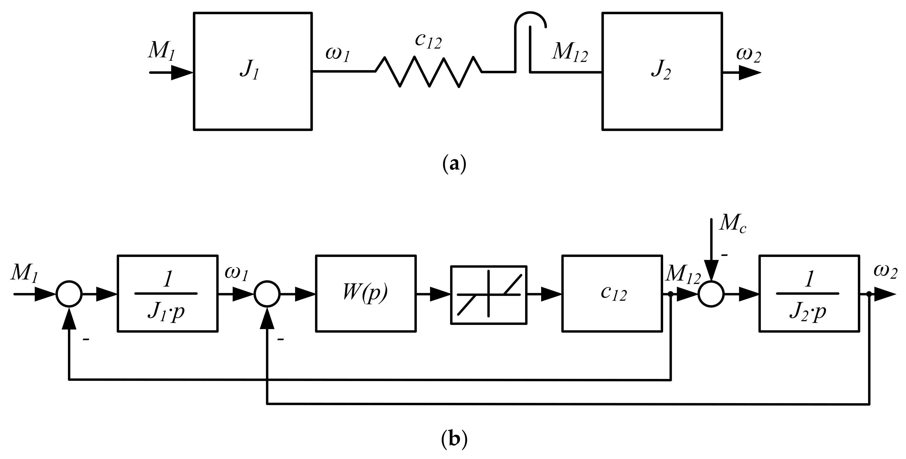
4. Dynamic Torque Limitation Principle

The decomposition of temporal dependencies and analysis of separate components of the elastic torque in a dual-mass electromechanical system with play substantiate the general principle (concept) of limiting dynamic loads at angular play closure. According to this approach, the following components of the dynamic torque ought to be compensated on an individual basis:
-
caused by an impact at angular play closure;
-
caused by elastic properties of the mechanical gear;
-
caused by settings of the automatic electric drive speed control system (ACS).
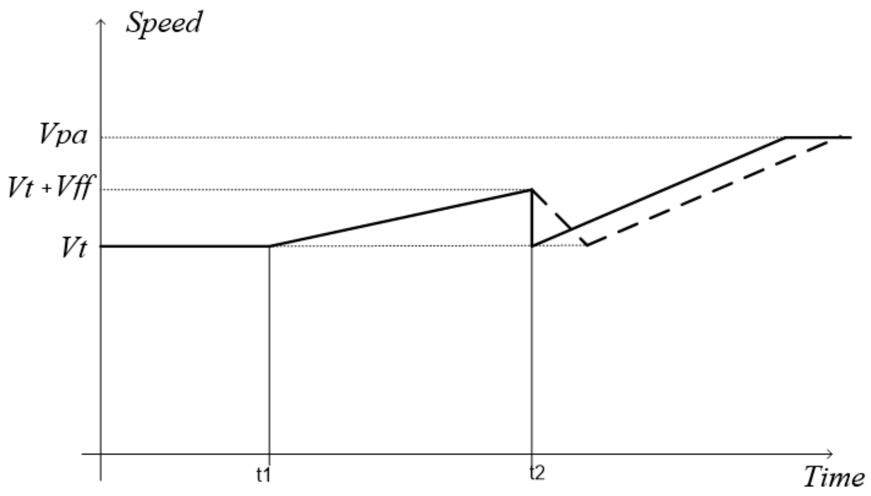
It is proposed to actualize this principle in electric drives of rolling mill stands by generating tachograms with positive and negative accelerations before and after metal capture, respectively. In a dual-mass system with shock loading, it is implemented as follows:
(1)
Before the shock loading, the system is pre-accelerated with the minimum initial acceleration to choose play regardless of its value. This helps to compensate for component M12δ caused by an impact (lower component of the elastic torque).
(2)
In order to compensate for component M12y, after the shock loading, the speed is reduced using set negative acceleration (deceleration rate).
This approach is a conceptual one, as it is applicable to any and all electromechanical systems featuring elastic coupling and gear play and may be implemented in different ways.
In order to apply it to the electric drives in the mill, the following control method has been developed:
-
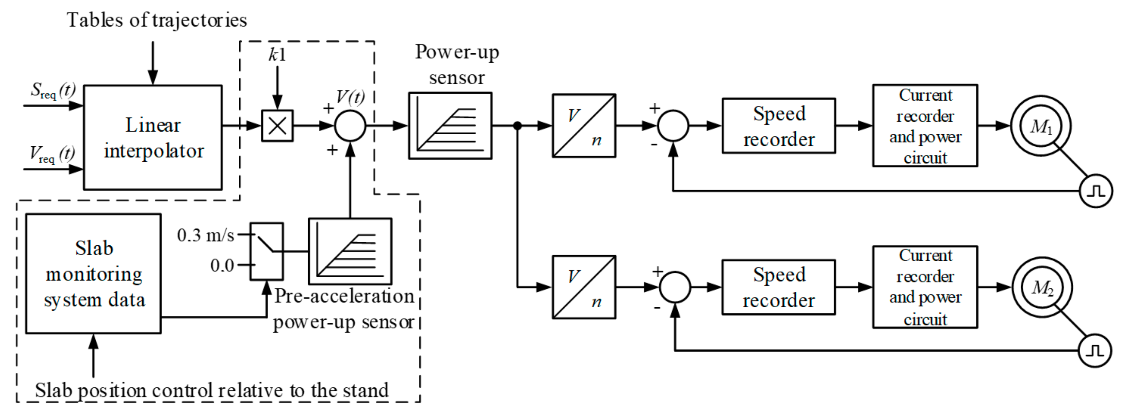
metal is captured when the electric drive is accelerated;
-
the speed at the time of capture must be equal to the value required to compensate for the dynamic speed control error;
-
when to start accelerating the drive is determined by the distance between the “head” of a slab and the stand calculated as follows:
S = ( V t + 0.5 V f f ) ( t 2 t 1 )
-
the speed is reduced after capture according to the linear law with set negative acceleration (according to simulation results, the optimal acceleration for the electric drive of rolling mill stand 5000 rolls varies from −2.5 to −3.5 rad/s2).
Figure 7 provides an explanation how to calculate distance from the head part of a slab to the stand using Equation (8). To calculate the required change rate Vff/(t2t1), known values of threading speed Vt and forward flow speed Vff (final pre-acceleration rate). This is used to calculate the distance from the “head” of a slab to the stand that is required for pre-acceleration to start.

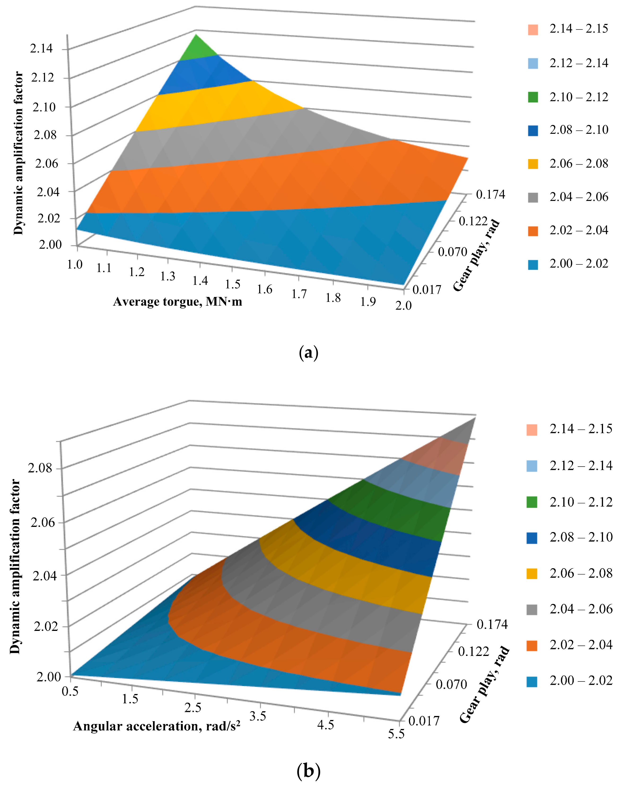
5. Discussion of the Results

According to the solid line in the tachogram in Figure 7, the post-capture deceleration may be achieved by reducing spike speed setting. However, it was observed that this option is not guaranteed to limit the dynamic torque in the engine, although it helps to achieve a satisfactory transient for the elastic torque in the shaft [22]. To resolve this disadvantage, the method substantiated above has been proposed to ensure speed reduction with set negative acceleration; it is explained by the tachogram fragment represented by the dashed line. It must be adapted to the electric drives of the plate mill; to do that, the optimal negative acceleration must be determined.
Besides, the research team has developed algorithms that provide speed controls invariant to the accuracy of metal positioning on the table, to which end, among other things, these algorithm ‘associate’ the pre-acceleration trigger with a specific position of the workpiece with respect to the stand.

6. Conclusions

Experimental studies of a method to control electric drives ensuring choice of play in spindle connections by metal capture in the acceleration mode demonstrated that this method does not guarantee the reduction of dynamic loads when metal is captured by rolls.
Temporal dependencies of the elastic torque in the shaft were decomposed to distinguish between the following components:
(1)
Caused by an elastic impact at angular play closure.
(2)
Caused by elastic properties of the shaft line.
(3)
Caused by settings of the automatic electric drive speed control system.
This allowed assessing the transients occurring during capture as a result of superposition of the three aforementioned impacts.
We found that the second-component amplitude at the baseline was 5–15 times higher than that of the first component, and therefore affected the maximum dynamic torque when the metal is captured by rolls more significantly. That was why the team sought to develop a control method to limit the amplitude of elastic oscillations.
We substantiated the concept of limiting dynamic loads at metal capture by rolls, according where to each of the elastic torque components is compensated on an individual basis to reduce their aggregate impact. This objective is resolved by generating tachograms providing for positive and negative accelerations of an electric drive before and after metal capture, respectively.
We developed a method to limit the torque, according whereto the electric drive speed is increased before the workpiece enters the stand to compensate for the dynamic speed slump at capture, and after the metal has been captured it is reduced to the baseline. This method helps to implement the proposed concept and combines advantages of the known ways to choose shaft line play by means of acceleration at the time of capture and advance speed increase to compensate for the dynamic speed control error. The developed method is recommended for industrial use in electric drives of the reversing stand of Mill 5000. In order to confirm its technical efficacy, it appears reasonable to conduct studies using the mathematical model approach, and experimental trials using the stand itself.

Author Contributions

Methodology, V.R.K.; software, V.R.G.; validation O.A.G.; formal analysis, S.S.V.; visualization, T.A.L.

Funding

This research received no external funding.

Conflicts of Interest

The authors declare no conflict of interest

References

  1. Artyukh, V.G. Fundamentals of protection of metallurgical machines from breakdowns. Mariupol Univ. 2015, 288. Available online: http://eir.pstu.edu/handle/123456789/6946 (accessed on 10 December 2019).
  2. Artyukh, V.G. Loads and overloads in metallurgical machines. Mariupol PGTU 2008, 246. Available online: http://eir.pstu.edu/handle/123456789/5751 (accessed on 10 December 2019).
  3. Artyukh, V.G.; Аrtyukh, G.V.; Mazur, V.O. Horizontal rolling forces. Mariupol Bull. Priazov State Tech. Univ. 2009, 19, 128–132. [Google Scholar]
  4. Mazur, V.O. Horizontal Strength during Rolling as an Indicator of the Manufacturability of the Rolling. Available online: http://nbuv.gov.ua/UJRN/Zmmvp_2013_15_4 (accessed on 9 September 2019).
  5. Ishchenko, A.A.; Kalinichenko, I.A.; Grishko, V.P. Experimental evaluation of shock loads on beds of working stands of plate mills. Stal 2009, 5, 56–58. [Google Scholar]
  6. Mazur, V.; Artyukh, V.; Artyukh, G.; Takadzhi, M. Current views on the detailed design of heavily loaded components for rolling mills. Eng. Des. 2012, 37, 26–29. [Google Scholar]
  7. Artyukh, V.G. Possibility of hot rolling of steel sheets of larger mass. Mariupol 2011, 13, 148–153. [Google Scholar]
  8. Russian Federation; Ministry of Industry and Trade of the Russian Federation. On approval of the Strategy for the Development of Ferrous Metallurgy in Russia for 2014–2020 and for the Long Term until 2030 and the Strategy for the Development of Non-Ferrous Metallurgy in Russia for 2014–2020 and for the Long Term until 2030. Available online: http://www.garant.ru/products/ipo/prime/doc/70595824/ (accessed on 9 September 2019).
  9. Denisov, S.V. Innovative achievements of PJSC MMK in the production of modern rolled metal. Magnitogorsk 2017, 2, 21–29. [Google Scholar]
  10. Khramshin, V.R. Ways to compensate for static deviations in speed in electric drives of broad-strip hot rolling-mill stands. Russ. Electr. Eng. 2013, 84, 221–227. [Google Scholar] [CrossRef]
  11. Kunitsyn, G.A.; Denisov, S.V.; Gorshkov, S.N.; Galkin, M.G. The commissioning of plate mill 5000 is a new stage in the development of rolled metal production technology at OJSC MMK. Metallurg 2009, 7, 4–5. [Google Scholar]
  12. Karandaev, A.S.; Loginov, B.M.; Gasiiarov, V.R.; Khramshin, V.R. Force limiting at roll axial shifting of plate mill. Procedia Eng. 2017, 206, 1780–1786. [Google Scholar] [CrossRef]
  13. Karandaev, A.S.; Loginov, B.M.; Radionov, A.A.; Gasiiarov, V.R. Setting Automated Roll Axial Shifting Control System of Plate Mill. Procedia Eng. 2017, 206, 1753–1760. [Google Scholar] [CrossRef]
  14. Gasiiarov, V.R.; Radionov, A.A.; Loginov, B.M.; Voronin, S.S.; Khramshin, V.R. Improvement of Work Roll Bending Control System Installed at Plate Mill Stand. In Proceedings of the 9th International Conference on Computer and Automation Engineering (ICCAE 2017), Sydney, Australia, 18–21 February 2017; pp. 269–273. [Google Scholar]
  15. Krot, P.V. Hot rolling mill drive train dynamics: Torsional vibration control and backlash diagnostics. Millenn. Steel China 2009, 91–95. Available online: https://www.researchgate.net/profile/Pavlo_Krot/publication/202044159_Hot_rolling_mill_drive_train_dynamics_torsional_vibration_control_and_backlashes_diagnostics/links/5c6d17c24585156b570ae2d2/Hot-rolling-mill-drive-train-dynamics-torsional-vibration-control-and-backlashes-diagnostics.pdf (accessed on 10 December 2019).
  16. Tselikov, A.I.; Polukhin, P.I.; Grebenik, V.M. Machines and assemblies of metallurgical plants. Machines and aggregates for the production of rolled metal. Metallurgiya 1988, 3, 680. [Google Scholar]
  17. Klyuchev, V.I. Drive dynamic load limitation. Energiya 1971, 320. Available online: https://lib-bkm.ru/load/65-1-0-1272 (accessed on 10 December 2019).
  18. Meshcheryakov, V.N. Development of a method for reducing dynamic loads of an electric drive of a rolling stand of a cold rolling mill. Electrotech. Syst. Complexes 2015, 3, 14–19. [Google Scholar]
  19. Verenev, V.V.; Bol'shakov, V.I.; Podobedov, N.I. The influence of the speed of capture of the strip on the dynamic loads in the drive stand. Fundam. Appl. Probl. Steel Ind. (IChM) 2007, 14, 260–266. [Google Scholar]
  20. Podobedov, N.I. Efficiency conditions for the use of acceleration of the rolling stand drive as a way to close gaps. Fundam. Appl. Probl. Steel Ind. (IChM) 2006, 12, 311–317. [Google Scholar]
  21. Karandaev, A.S.; Gasiiarov, V.R.; Maklakova, E.A.; Loginov, B.M.; Khramshina, E.A. Method limiting dynamic loads of electromechanical systems of plate mill stand. In Proceedings of the 2018 IEEE Conference of Russian Young Researchers in Electrical and Electronic Engineering (EIConRus), Moscow and St. Petersburg, Russia, 29 January–1 February 2018. [Google Scholar]
  22. Khramshin, V.R.; Gasiiarov, V.R.; Karandaev, A.S.; Baskov, S.N.; Loginov, B.M. Constraining the Dynamic Torque of a Rolling Mill Stand Drive. Bull. South Ural State Univ. Ser. Energy 2018, 18, 101–111. [Google Scholar]
  23. Shubin, A.G.; Loginov, B.M.; Gasiiarov, V.R.; Maklakova, E.A. Substantiation of methods for limiting dynamic loads of electromechanical systems of a mill stand. Electrotech. Syst. Complexes 2018, 1, 14–25. [Google Scholar] [CrossRef]
  24. Evdokimov, S.A.; Khal'ko, A.I.; Dorofeev, A.M. A telemetry system for measuring elastic torque in spindles of horizontal rolls of the working stand of mill 5000. Energy Electr. Syst. 2015, 375–382. [Google Scholar]
  25. Salganik, V.M. Modern technologies for the production of sheet metal. In Proceedings of the Innovative Technologies in Metallurgy and Mechanical Engineering: Materials of the 6th International Youth Scientific-Practical Conference Innovative Technologies in Metallurgy and Mechanical Engineering, Golovin Ural Scientific and Pedagogical School, Yekaterinburg, Russia, 29 October–1 November 2012. [Google Scholar]
  26. Verenev, V.V.; Podobedov, N.I.; Belodedenko, S.V. Monitoring the dynamic loading of roll lines of a plate mill stand. Metall. Min. Ind. 2015, 7, 110–113. [Google Scholar]
Figure 1. Stand roll line, Mill 5000 (a), spindle connection and angular gap closure detailed (b).
Machines 07 00076 g001
Figure 2. Functional chart of the electric drive speed control system (contoured blocks are the ones that provide pre-acceleration).
Machines 07 00076 g002
Figure 3. Waveforms of engine torques (a) and elastic torques in the spindle shafts of the top and bottom rolls, horizontal stand, Mill 5000 (a,b).
Machines 07 00076 g003
Figure 4. Kinematic configuration of a dual-mass system with elastic coupling and play (a) and the structural layout of the model (b): J1 = JE—first mass (engine) moment of inertia; J2—given second mass moment of inertia (work and backup rolls); c12—stiffness of the elastic coupling; M12—elastic torque; W(p)—transfer function of the mechanical part.
Machines 07 00076 g004
Figure 5. Torque component change graphs (disregarding dissipative forces): 1—elastic torque M12 in the shaft; 2—component M12δ caused by elastic impact; 3—component M12y caused by elastic oscillations; 4—static load torque M12c.
Machines 07 00076 g005
Figure 6. Dependencies of the dynamic amplification factor on the average torque and gear play at constant angular acceleration (a), and on angular acceleration and play at the nominal torque of load (b).
Machines 07 00076 g006
Figure 7. Explanation to the calculation of distance from the “head” of a workpiece to the stand.
Machines 07 00076 g007
Table 1. Parameters of the dual-mass system in the Mill 5000 electric drive.
ParameterDesignationValue
Stiffness of the elastic couplingc125,934,842 N·m/rad
Moment of inertia of the first moving mass (engine)J1125,000 kg·m2
Moment of inertia of the second moving massJ2114,571 kg·m2
Natural frequency of elastic oscillationsω129.96 rad/s
Initial acceleration of the electric driveε01–3 rad/s2
Gear playδ1–10°
Average elastic torqueM12c1.9 MN·m

