Article

Overcoming the Challenges for a Mass Manufacturing Machine for the Assembly of PEMFC Stacks

by
Sebastian Porstmann
1,*,
Thomas Wannemacher
2 and
Thilo Richter
3
1
Fraunhofer Institute for Machine Tools and Forming Technology IWU, Reichenhainer Strasse 88, 09126 Chemnitz, Germany
2
Proton Motor Fuel Cell GmbH, Benzstrasse 7, 82178 Puchheim, Germany
3
Aumann Limbach-Oberfrohna GmbH, An der Hopfendarre 11, 09212 Limbach-Oberfrohna, Germany
*
Author to whom correspondence should be addressed.
Machines 2019, 7(4), 66; https://doi.org/10.3390/machines7040066
Submission received: 11 September 2019 / Revised: 10 October 2019 / Accepted: 14 October 2019 / Published: 18 October 2019

Abstract

:
One of the major obstacles standing in the way of a break-through in fuel cell technology is its relatively high costs compared to well established fossil-based technologies. The reasons for these high costs predominantly lie in the use of non-standardized components, complex system components, and non-automated production of fuel cells. This problem can be identified at multiple levels, for example, the electrochemically active components of the fuel cell stack, peripheral components of the fuel cell system, and eventually on the level of stack and system assembly. This article focused on the industrialization of polymer electrolyte membrane fuel cell (PEMFC) stack components and assembly. To achieve this, the first step is the formulation of the requirement specifications for the automated PEMFC stack production. The developed mass manufacturing machine (MMM) enables a reduction of the assembly time of a cell fuel cell stack to 15 minutes. Furthermore the targeted automation level is theoretically capable of producing up to 10,000 fuel cell stacks per year. This will result in a ~50% stack cost reduction through economies of scale and increased automation. The modular concept is scalable to meet increasing future demand which is essential for the market ramp-up and success of this technology.

1. Introduction

Since the beginning of industrialization, the storage of large amounts of energy has been a challenge for our society. Today, more than ever before, we understand the importance of direct power generation by solar, wind, water, and hydrothermal power plants. Electricity generated from these energy sources is known as green electricity because of its zero CO2 balance and the absence of NOx emissions. Although the production of the power plant has some carbon footprint, its operation is emission free. These power sources are intermittent, and the off demand energy surplus has to be stored because the power grid cannot handle it. A challenge of using these energy sources is to store the electrical energy whenever it is available in the most efficient way.
The importance of sustainable energy production with a less severe impact on the environment, e.g., reduction of greenhouse gas emissions (i.e., atmospheric concentration), is a main concern of the EU and the 2030 climate and energy framework. This framework identified three key targets through which to improve the current situation [1].
  • At least a 40% cut in greenhouse gas emissions (compared to 1990 levels),
  • At least a 32% share for renewable energy,
  • At least a 32.5% improvement in energy efficiency.
A very promising path in this context is the use of hydrogen-based technologies, which are experiencing a renaissance because of their energy storage potential. This can be realized by using electrolysis to transform the surplus generated electric power to hydrogen.
More than ever, this necessity has been driven by political demands, general rethinking, and a new mindset in our society. The interest of the population has risen. There are numerous concepts of what a future hydrogen-based economy could look like, and rough calculations are available regarding the measures necessary for its implementation. If its implementation is successful, hydrogen may become one of the main energy carriers and fuels in the future. To achieve product sales in the field of hydrogen technologies, there are still some technological, infrastructural, and economic challenges to be solved. Established barriers currently include a comprehensive infrastructure at H2-refuelling stations, the available polymer electrolyte membrane fuel cell (PEMFC) stack production capacity, and costs.
An example of a fuel cell range extended electric vehicle (FCREEV) is described in [2]. A FCREEV is an electric vehicle equipped with a PEMFC to recharge the on-board battery and thus facilitate range extension in such emission-free hybrid drives. Furthermore, some automotive original equipment manufacturers (OEMs) already have launched fuel cell vehicles and cars (FCV) on the market [3]. The literature published on highly automated fuel cell stack assembly is sparse. Some existing and specifically useful information can be found regarding automated stack manufacturing [4,5,6,7]; however, very little information is currently publicly available in this area. In general, focused aims in the course of this development consist of the definition of quality requirements, specifically in control and compliance, process reliability, and the reduction of production costs.
A complete fuel cell system, as part of the drive train of an electric vehicle, consists of many components supporting the PEMFC stack, including a compressor creating the reaction air supply, a hydrogen supply including a recirculation pump, a heat management module with heat exchangers and coolant pumps, and power electronics. The performance/power output of a PEMFC stack depends on the size of the active cell area or the number of single cells. One single cell comprises a bipolar plate (BPP) with an anode and a cathode side, two gas diffusion layers (GDL), and a catalyst coated membrane (CCM) between the GDLs. Figure 1 provides an exemplary overview which also takes into account the sub-assemblies’ hierarchy [3]. The MMM will produce the PEMFC stack by assembling the single components shown in Figure 1a, framed in green.
A cost distribution for the total system is presented in Reference [8], with ~44% allocated to the PEMFC stack and ~56% to the balance of plant (BOP). The BOP consists of subsystems. The main cost drivers of the BOP are the air circuit with ~46%, the coolant circuit with ~20%, and the fuel circuit with ~16%. The manufacturing costs of a PEMFC stack consist of the pro-rata development costs, the costs of the individual parts or components (Figure 1), and the pro-rata costs of assembly. Literature sources [9,10] present the cost shares of components of a PEMFC stack for different quantity scenarios; however, the marginal conditions and costs of assembly are not explained in detail. Therefore, it is difficult to derive a classification or representation of the proportional costs for the assembly of the fuel cell stack based on References [9,10]. Figure 2 shows a summary of the redemption-dependent cost-saving potential for the components of a PEMFC stack from References [4,9].
The column diagram shown in Figure 3 can be derived from Figure 2. It shows that if production rates increase to 10,000 units/a compared to production rates of 1000 units/a, a significant reduction of component costs of ~69% already seems to be achievable. However, with a further increase of the production rate, this effect exhibits diminishing returns. For example with a production rate of 100,000 units/a, the reduction of costs amounts to ~82%, and with 500,000 units/a, the reduction of costs reaches ~84%. This data also allows the derivation that a reduction of the stack costs of ~51% will be achieved based on a production rate of 10,000 units/a, when further increasing the production rate to 500,000 units/a.
The contribution of the PEMFC component costs varies greatly depending on the production rate, because the manufacturing costs consist of the material costs and the costs for the processing steps. While the latter can be significantly reduced with the quantity produced (such as GDL), above all, due to adapted production methods, the material costs, especially of noble metals (such as catalyst formulation, e.g., Pt etc.), are largely independent of economies of scale. These are mainly dependent on the respective raw material prices, which are also subject to fluctuations over time, but which are far more difficult to calculate and, moreover, tend to increase with increased demand.
Figure 4 illustrates the cost analysis presented in References [4,9] for the development of the cost distribution of a PEMFC stack depending on different production rates. Based on the results of References [9,10,11], it can be deduced that the relative cost shares of the PEMFC stack components shift with increasing production rates. At a production rate of 1000 PEMFC stacks/a, more than 80% of the material and manufacturing costs are due to four components: the bipolar plates (BPPs); the membranes; and the catalyst, including its application; as well as the gas diffusion layers (GDLs). However if the production rate is increased to 500,000, ~70% of the stack costs will be caused by two components: the BPPs and the catalyst, including its application. Thus, these two components were identified as the main cost drivers for production rates from ~100,000 [4,9].
When identifying and classifying the contribution of assembly costs within the total stack costs, one challenge is the interpretation of the published values and boundary conditions and bringing them into a single consistent framework. Thus, Reference [8] asserts that the assembly costs per PEMFC stack have a savings potential of more than 50% if the production rate is increased from 1000 to 500,000 units/a. If the cost share of the assembly is considered separately, according to Reference [8,9,10,11], it amounts to ~1% for production rates of 1000 units/a, 3% for 10,000 units/a, and 4.1% for 500,000 units/a. From the preceding considerations on the cost development, it can be concluded that the costs of all items recorded in References [8,9] could be reduced with increased production rates. Compared to the other items, the costs for assembly are only reduced by increasing the production rate to a lower extent, and thus the cost share increases, according to Reference [10]. Increasing the production rate reduces the costs of manufacturing parts and assembling components to a greater extent. This increases the relative cost share despite the associated reduction in assembly costs. Nevertheless the costs for the more highly processed components of the stack (as well as most parts of the BOP, compressors, pumps, sensors, etc.) are naturally subject to certain economies of scale. This alone reduces procurement costs with increasing purchase volumes. Furthermore, the automated process steps of the mass production plant described in this article result in significant savings in production time and personnel requirements for the production of fuel cell stacks. In addition, completely new component concepts can be used in the transition from a manual stacking process to an automated process, which were not easy to implement before. Both factors are decisive for a further reduction in manufacturing costs.
Selected publicly funded research projects, which started in the period of 2012 to 2018 and mainly or partially deal with FC stack production, include DigiMan [12], Fit-4-AMandA [3], Inline [13], Inn-Balance [14], MAMA-MEA [15], VolumetriQ [16], Autostack Core [17], Autostack Industry [18], and MontaBS [19].
At the end of 2018, Elring Klinger published a report which showed the demand for and focus on the industrialization of PEMFC stack production regarding quality, cost, and customer relationships [20]. They presented their point of view on the challenges related to the realization of high and very high volume stack production (5000 to 20,000 stacks/a), and a very high volume production (>100,000 stacks/a) of a 400 cell stack. The required target values for rejected stacks were set at <1%, which means a failure rate of ~1 ppm for single components of the repeating units.
Approaches for realizing such high production volumes were presented, such as parallelization, throughput optimization, and continuous processing (e.g., progressive die sets) based on a scalable and modular production concept [10]. Furthermore, laboratory facilities can be researched, which provides approaches for automated or manual assembly of FCs or FC stacks, and is explained in more detail in References [5,6,7]. The scarcity of references on the subject of mass production is assumed to indicate that this is not the current focus of academic activity. The subject of mass manufacturing is, however, the daily business of machine and plant manufacturers and their customers who want to manufacture products in high volumes (e.g., Tier suppliers). Typically, standardized components and assemblies (drives, assembly lines, robots, etc.) are used. There are several publications on the topic of automated assembly lines, e.g., References [21,22,23], from which general approaches to methodology can be derived. However, the specific developments are mostly confidential and unpublished.
An insight into the sequence/process of a manual PEMFC stack assembly is given in Reference [5]. The manually handled bipolar plates (BPPs) with a seal applied on the lower end plate are stacked sequentially. A three-axis/directional system is used to ensure vertical positioning accuracy. The fuel cell stack itself consists of a number of single cells. This sequence is repeated until the stack reaches the final cell count. Finally, the upper end plate is positioned and the PEMFC stack is compressed with an appropriate restraint concept (commonly tie rods) in a hydraulic press to obtain a uniform pressure distribution over the whole stack before it is released from the press in the final processing step.
A semi-automated production for stack assembly of solid oxide fuel cell (SOFC) using with two Kawasaki robots is presented in Reference [6]. One six-axis robot sets the components to the camera position. Afterwards, a second six-axis robot takes and stacks them. The components to be stacked are supplied through several parallel and vertically arranged shafts.
Further interesting approaches for a semi-automated stack assembly plant are presented in Reference [7]. The company “JEFFREY GUEBLE—Director of Engineering at Zetec Inc” built this plant for stacking for the company Ballard Fuel Cell Systems Inc. A robot is used to realize stacking in a simple sloping tower. The supply takes place via adjustable shaft magazines, in which the robot travels exclusively. The system has a turntable for rotating the inclined or slightly tilted press unit. The upper media module is guided during pressing in order to compress or tension the stack. The stack is secured in position during pivoting. The possible or targeted production volumes are not described in more detail in References [5,6,7].
To develop and provide an automated plant ready for mass manufacturing, numerous requirements must be fulfilled. The main requirements are [3]:
  • Repeating accuracy,
  • Precision,
  • Automated handling of fragile components (sensitive regarding their robustness),
  • Automation-oriented provision of the individual components,
  • High-level technological flexibility to be able to handle different materials and component designs, while fulfilling requirements which come from scalability demands, etc.,
  • Possibility of tracking of products and batches (traceability).
This is associated with certain risks and requires maximum development performance, which will be discussed in more detail in the following sections.

2. Approach and Methodology

No standardized method to compile requirement specifications for specialized automated manufacturing machines for PEMFC stacks currently exists. In this instance, a top-down approach was used to define the technical conditions.
The base for defining the boundary conditions of the PEMFC stack manufacturing machine is in principle given by the stack design (e.g., dimensions); the variety of stack variants to be realized in the form of expansion stages, which requires a corresponding degree of machine flexibility; and, last but not least, the targeted production rate of stacks per year. The initial situation and knowledge base for batch production with regard to the necessary work steps is given by the existing non-automated manufacturing procedure of Proton Motor fuel cell GmbH. It forms a solid foundation and provides valuable insights for analysis of the design and tools required for the automated manufacturing machine needed to compile the specification list. The list requires specifications for designing the machine. Therefore, a check was also carried out through a gap analysis including
  • Fuel cell manufacturers—taking into account a customer’s demand analysis,
  • Experts in component manufacturing,
  • Special mechanical engineering companies,
  • Experts in quality assurance and analysis.
The surface area for chemical reaction (active area) in a stack is a critical performance criterion. Due to its function and design, this active surface is smaller than the actual overall area of the stack or cell. The reason for this lies in the integration of necessary stack components such as the manifolds and the restraint system, which require considerable space. Therefore, the active area must be distinguished from the actual area of the stack. The overall area determines the width and length of the stack, while the height depends on the number of cells and the thickness of the end plates. The plant is intended to be flexible enough to be capable of the production of different stack formats from ~280 cm2 (Proton Motor’s small stack format PM200) to ~580 cm2 (large format PM400). Only a second set of tools and fixtures need to be allocated for this purpose. Furthermore, it is possible to handle and process different materials, such as metallic or composite graphitic BPP. Estimations made based on these details were required to determine how many separate units with specific functionalities the machine needed to comprise. Estimates were made of the space required for the plant and the achievable output cycle times (most of the processing and the design steps of the plant). In addition, the following considerations were taken into account:
  • Required and foreseeable changes in the fuel cell product,
  • Stacking size, form, and outline of the active area,
  • Various/different component suppliers,
  • Quality fluctuations of components,
  • Tolerance specifications—alignment feature—with the sum-up of tolerances from the stack components on the required stacking height.
The development process for a mass production machine for the automatic assembly of fuel cell stacks is a process simultaneously involving the developer of fuel cell stacks, the technologist, the component suppliers, and the special machine manufacturer with the assembly and automation knowledge.
The development, manufacturing, testing of technology and machine systems for the automatic assembly of PEMFC stacks therefore includes:
  • Elaboration of a “development concept” for the technology and machine system design for an automated assembly system for PEMFC stacks, including the underlying processing steps and their requirement specifications;
  • Redesigning the product to be suitable for automated manufacturing, assembly, handling, transportation, image processing, and inspection;
  • Development of the production processes for manufacturing PEMFC components and the production processes required for this machine system, including storage, handling, and supply systems for the components;
  • Manufacturing, assembly, and commissioning of a prototype machine system;
  • Testing, validation, and qualification of products, technology, and test equipment by manufacturing PEMFC stacks;
  • Sampling or functional verification of the automatically assembled PEMFC stacks.
The process started with the development of the technology concept and the design of the machine systems. First, the product technology was defined, starting with the specific requirements resulting from the selected reference product, and then generalized using the requirements of the representative PEMFC stacks and technologies on the market. Thus, a process concept with modules for different production technologies was developed and evaluated regarding cycle time, accuracy, and automation requirements. As a result, the process variants that were to be integrated into the prototype machine system were defined. The concept of the machine system was developed with regard to cycle time, dimensions, and characteristics. The characteristics resulted from the decisions regarding the integration of manual or automated and independent or assembly-integrated processes. Specific process variants are discussed in Section 3.3.
A modular machine system was developed based on this, which is suitable for the various process technologies, flexible in layout, scalable in throughput, and adaptable to customer requirements in different variants. This resulted in the general requirements for the infrastructure required for plant operation. To convert from manual to automated production, the product design needed to be adapted for the mass manufacturing, including but not limited to component manufacturing, transport, handling and assembly, automation, testing, e.g., by optical methods, and the associated image processing. In manual single part production, skilled workers can carry out processes that cannot be directly automated, e.g., grasping a part manually from bulk material, aligning it, and inserting it into a fixture.
In order to manufacture a PEMFC stack automatically, the mechanical design of the product must fulfil certain requirements of the manufacturing steps. Hence, it was essential to define the necessary properties of the PEMFC stack components with regard to near-series automation and to summarize these in a requirement specification. The precise stacking of PEMFC components (GDL + CCM or seven layer MEA and BPP) was analyzed for possibilities of position detection, and optimized accordingly for the vision system and for part measurement and position detection with high-precision pick-and-place positioning in short cycle times. Several concepts are possible for designing a single cell, such as:
  • GDL with a molded seal + die cut,
  • MEA consisting of a CCM with sub gasket and laminated GDL (+ possibly sealing).
Furthermore, investigations were carried out regarding the suitability of the components for automated feeding via pick-and-place positioning for automatic stacking. For this purpose, practical tests for part feeding and separation of stacks with and without an intermediate layer with vacuum grippers in different specifications were necessary in order to sufficiently evaluate the specific properties of the individual PEMFC components. These tests qualified two supports for GDL feeding.
The investigation’s results and the recommendations for component design adaptations in terms of close-to-production automation were:
  • Use of a restraint system which can easily be implemented in an automated process;
  • Use of the same design principles, manufacturing technologies, and assembly sequence for different types, with preference for the application of modular and scalable technologies;
  • Use of part identification with a data matrix code (DMC) or barcode for automated tracking of parts and batches (traceability);
  • Use of separate GDL bottoms and tops instead of a foldable combination;
  • Use of a CCM supply from the roll, with cutting of the membrane in the assembly system to reduce CCM handling effort and avoid complex separation of CCM stacks;
  • Provision of metallic or graphitic BPP of stacks without intermediate layer;
  • Development of stacking supply boxes and intermediate layers (specially coated intermediate layers for separation in single items) for flexible and highly adhesive sealing on GDLs;
  • Redesign of the components to have a uniform thickness over the entire surface, in order to obtain straight supply stacks without sagging;
  • Assembly of the membrane electrode assembly (MEA consists usually of CMM+GDLs, sub gasket and sealing) in an air-conditioned environment to protect the CCM.
To produce high quality products and PEMFC stacks, it is particularly important to repeatedly, precisely, and accurately position the stack components during assembly to minimize the production error rate. For this purpose, appropriate alignment contours must be included in the new design or component adaptation. This concerns the vast majority of the stack components, including GDL, MEA, and BPP. Figure 5 shows the device for restraining the PEMFC stacks as part of the automated production and assembly line.
The following requirements were to be fulfilled with the product redesign:
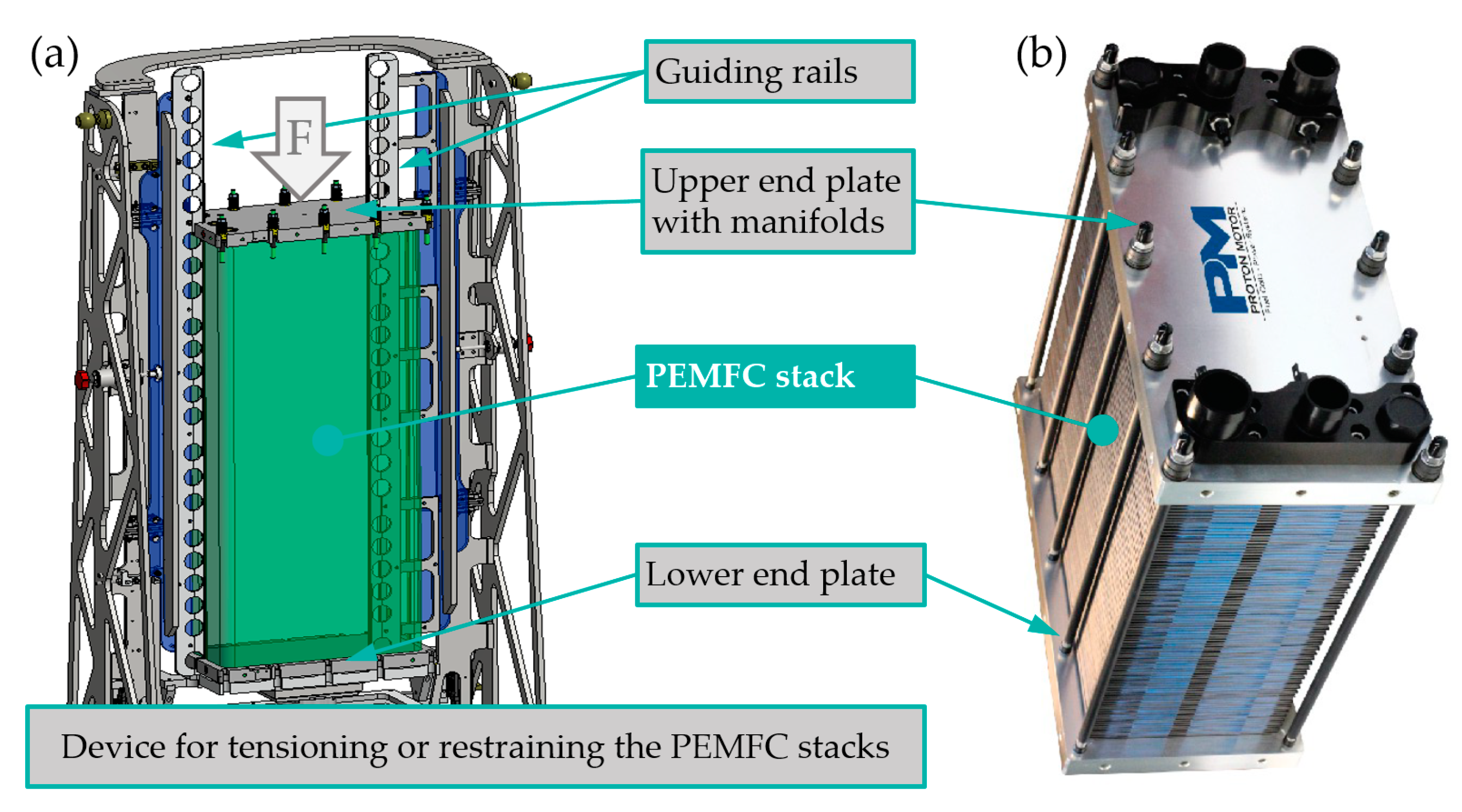
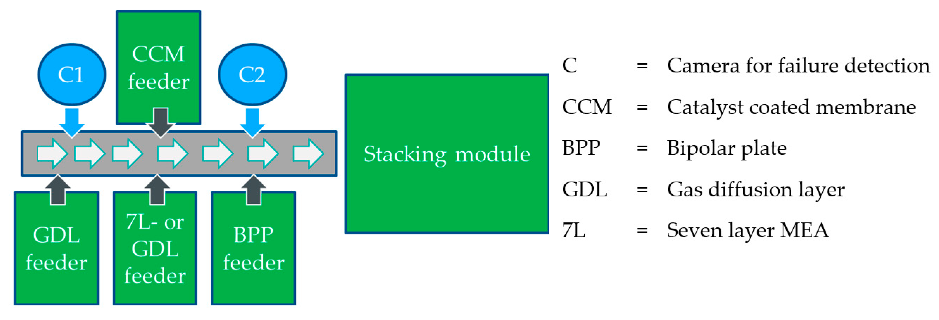
  • The integration of alignment contours for all stack components for alignment on the guide rails, as shown in Figure 5, of the stacking unit over the entire stack height, including end plates and seals;
  • The coordination of the alignment contours to define the position of all components, from the lower end plate via BPP and MEAs to the upper end plate;
  • Design of alignment contours on the end plates which set the initial positioning in addition to the guide rails;
  • The upper end plate must be fixable to the upper adapter plate of the device for restraining.
When designing the restraining device or process for restraining the precisely assembled stack, the following must be observed:
  • For restraint systems with a tie-rod design, sufficient space is required for the electric screwdriver and nut as well as the plug-in attachment for torque transmission;
  • Monitoring the accessibility of the automatic tools to the product (e.g., straight or offset screwdrivers);
  • The clamping system can be mounted from the outside—no run-in of tie rods necessary;
  • The force transmission points when pressing the stack should be close to the force transmission points of the clamping system (bending line);
  • To measure the height of the clamped stack by means of a sensor, detectable outline elements must be provided at the edges;
  • For picking up a load-carrying device, torque profiles are required.

3. Results

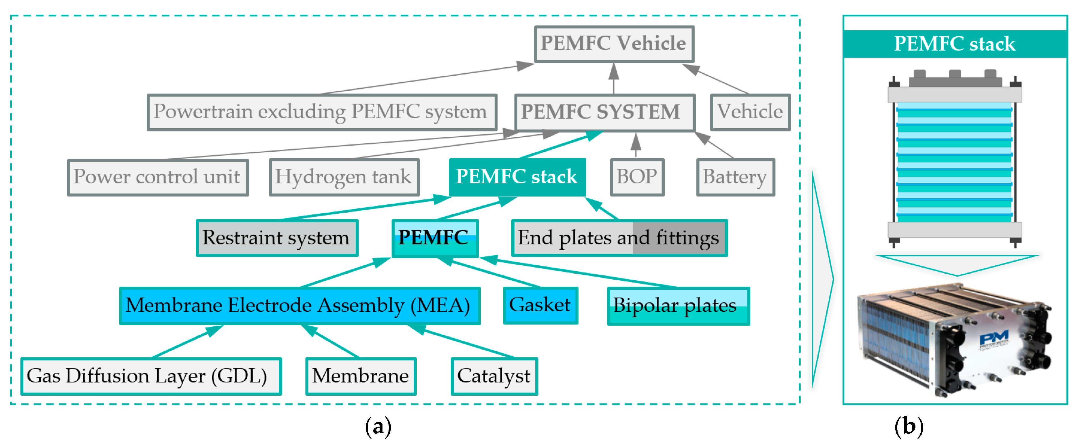
3.1. Overview of the Key Performance Indicators (KPIs) for PEMFC Stacks

For the mass manufacturing machine to be developed, a target production rate of 10,000 stacks/a was defined, based on an estimate of realistic yearly demand in the medium term. This assumption referred to stacks which are primarily intended for applications such as range extenders and decentralized energy stations. Furthermore, the knowledge gained should provide a solid basis for safety analysis for a theoretical extension of the production rate to 50,000 PEMFC stacks/a.
The key performance indicators (KPIs) and innovations to be achieved in the EU funded project “Fit for Automatic Manufacturing and Assembly”, “Fit-4-AMandA” are summarized in Table 1.

3.2. Requirements for Mass Manufacturing

Requirement gathering is one of the most important stages of the methodology. The essential steps are:
  • Identification of bottlenecks in the stack components and assembly, which can be evaluated by cycle time, throughput time, and efficient testing efforts such as burn-in-time (the process during which the stack reaches the nominal specifications);
  • Redesign (adaptation) of current MEA and stack to optimize for manufacturability;
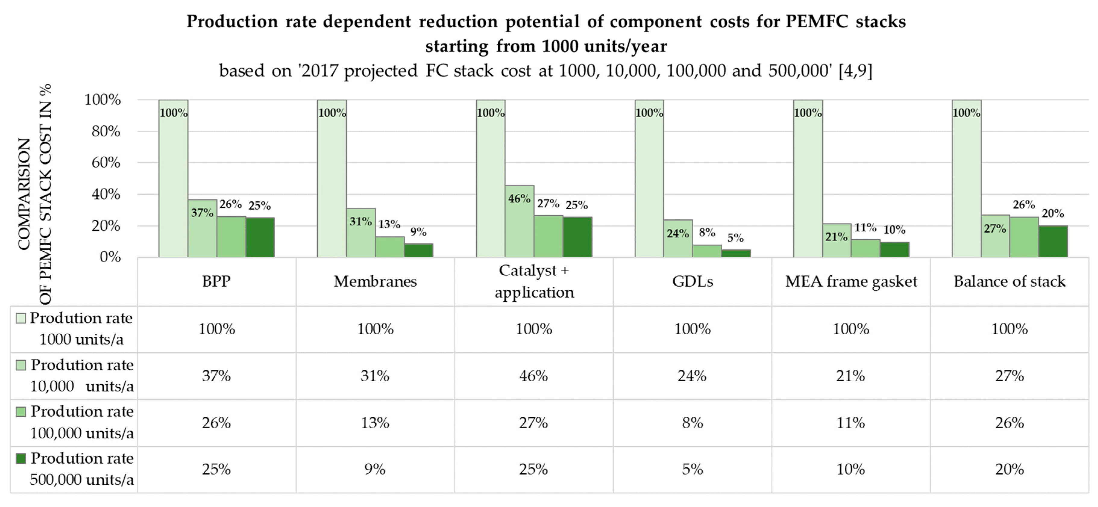
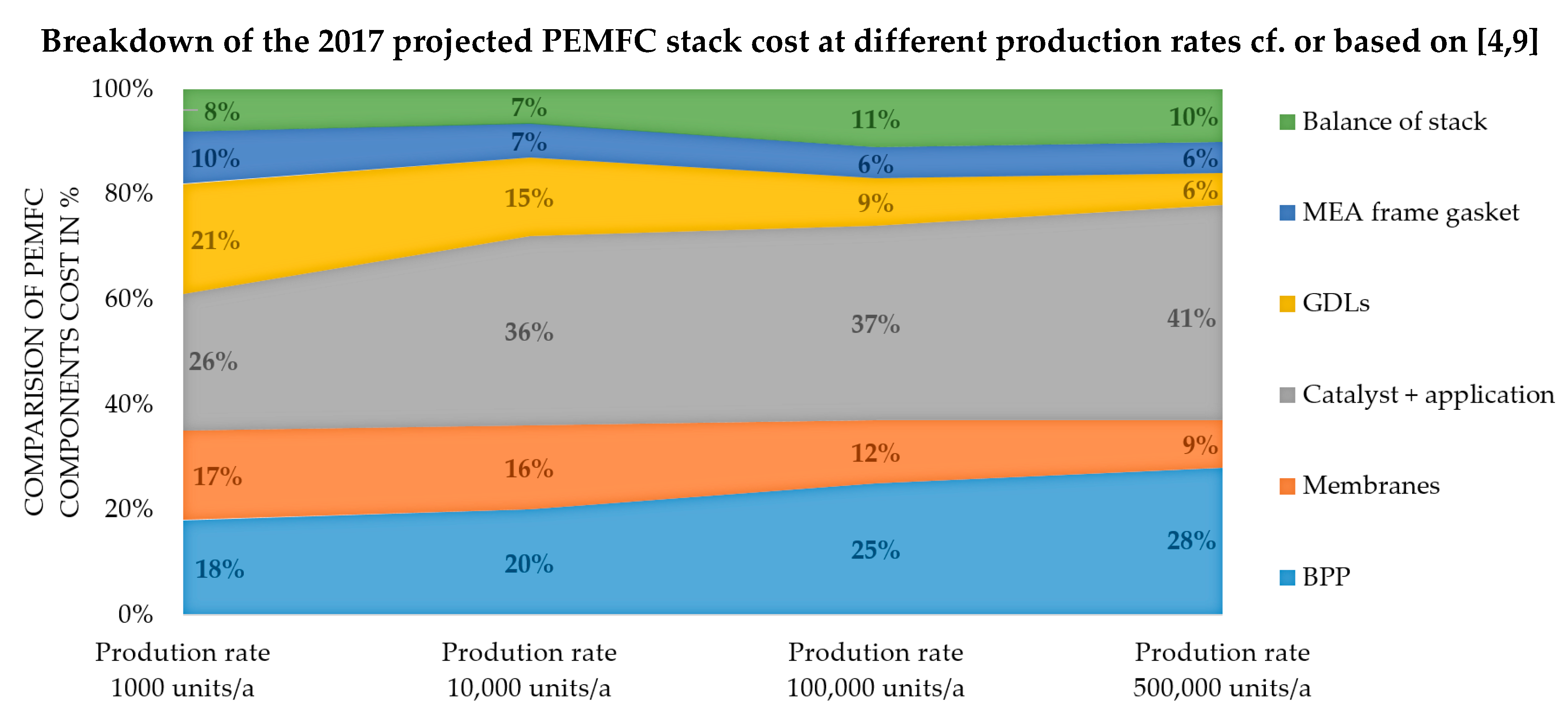
  • Analysis and evaluation of the most suitable bipolar plate material with regard to the performance and service life requirements as well as the expected quantities: graphitic vs. metallic concept.
Figure 6 shows the individual steps for the stack manufacturing process schematically.
The strategy used for the stack assembly process to redesign the complete product (stack) enables the machine, for example, to pick components with automated pick-and-place processes. An upgraded infrastructure for the mass manufacturing machine includes an improved production layout.

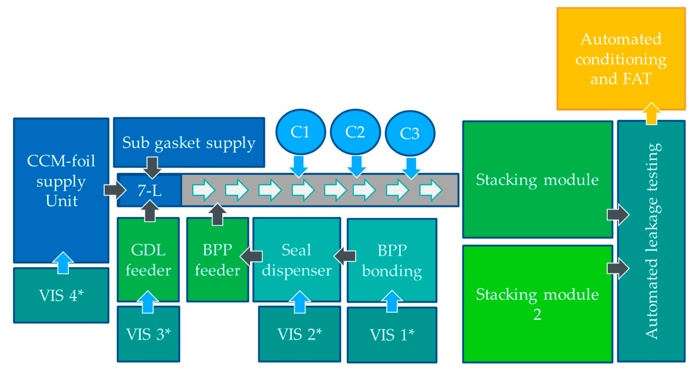
3.3. Development of Technolgy Concept and Machine System Design

The development met the requirement to produce a modular system with a high degree of flexibility. The requirements with regard to flexibility related to the manageability of different stack designs, BPP materials, dimensions, and the possibility of further automation, expanding, or modernizing the MMM. Furthermore, the feasibility of different batch sizes was of importance. Such a highly flexible machine set-up is necessary for an upcoming market such as the FC stack market to be able to realize the current production and to be ready for the near future.
For the configuration of the developed machine, a reduced in-line test procedure was initially planned, i.e., a reduced number of cameras for positioning and failure detection (C1 and C2 as shown in Figure 7). In the first expansion stage, the automated assembly line was able to handle the following tasks and challenges.
  • Handling of either seven-layer MEA or seal-on GDL/CCM was possible without changing the configuration;
  • Graphite–polymer composite or metallic bipolar plates stacking;
  • At least two stack formats with different cell numbers (with minor adaptions) were producible.
The schematic illustration in Figure 8 show a 3D-CAD layout of the MMM for the automated production and assembly of FC stacks and illustrates the subdivision of the plant into component feed and assembly or stacking.
Figure 9 shows an ideal machine concept from the current point of view. The following main differences in comparison to the MMM in the expansion stage 1 (as depicted in Figure 7) are:
  • Fixed on one MEA architecture (seven-layer MEA),
  • Enhanced in-line test methods for failure detection,
  • Parallelization of multiple production lines possible,
  • Additional units, e.g., second stacking module, automated conditioning, and factory acceptance test (FAT).
In the case of increasing demand, the system can be extended modularly. Figure 9 illustrates a schematic representation of how the plant can be modularly expanded as an example of a second expansion stage.

3.4. Balance between Manufacturability and Stack Performance

The reduction of the production costs of fuel cell stacks is one of the greatest challenges facing the modern fuel cell industry, and is influenced by many factors. Figure 10 shows that a significant reduction in stack production costs results can solely from an increase in units produced. Note that the share of personnel costs is independent of the number of produced units.
The demand for qualified personnel for non-automated stacking would increase dramatically with volume, and it becomes increasingly difficult to find suitable qualified employees. The presented calculation does not account for the additional costs related to premises, utilities, and infrastructure. For this reason, the increase in production volume is subject to market economy limits.
The second major factor in reducing production costs is the selection of the appropriate technology. A very big step with a dramatic change in production costs is possible by switching to another technology. In this case, the switch from the seal-on GDL + CCM concept to the seven-layer MEA has been used as an example. For smaller quantities and in manual manufacturing, the concept of a seal-on GDL is not as prone to mishandling and inaccurate stacking as the seven-layer MEA alternative. With automated production at high production volumes, the transition to a seven-layer concept for the MEA results in a dramatic reduction of product costs [3]. In detail, the MEA is the combination of the gas diffusion layer, the catalyst layer, and the membrane, so in this case, the membrane coated from both sides with catalyst layers (CCM, three layers) and a sub-gasket, the GDL (two layers), and a separation of the respective gas spaces of an anode and cathode with a seal/gasket (two layers). Although this means a higher effort and thus higher costs for the production of the seven-layer MEA, the TCO (total cost of ownership) consideration leads to a significant reduction due to the considerably simpler and more cost-effective GDL without an injected seal. Additionally, handling by the MMM is easier and faster. The transition from one technology to another is usually associated with complications. This should be taken into account when designing the mass manufacturing machine. Therefore, the flexibility of the machine to handle both concepts was a basic requirement for the selected approach. This always offers a fallback option, even in the case of the loss of one supplier or technology.
Of course, the production and material costs of base materials and components such as the BPP, GDL, and CCM (or MEA) at the supplier are also decisive, but will also decrease significantly with increasing production volumes. In contrast to earlier studies, the costs of precious metal catalysts such as platinum are now considered relevant but not crucial. The content of platinum in FC stacks is drastically lower than it was a few years ago, and is expected to decrease even further in the future. Moreover, it is possible to feed used fuel cell stacks into a suitable disassembly or recycling process and to recover the precious metal with recovery rates of ~90% [25]. However a research demand exists for developing options for the design of a future recycling system regarding cost and total recycling chain efficiency [25].
In the end, a dramatic step down to one third of the initial stack production costs may be the result of the implemented actions. Since the machine, with its high flexibility, is able to implement further modules and new concepts, further potential for improvements and cost reduction opens up. The proof of these expectations may only come from the market ramp-up of the fuel cell technology and the resulting high demand of fuel cells, but the technology of the machine is well prepared.

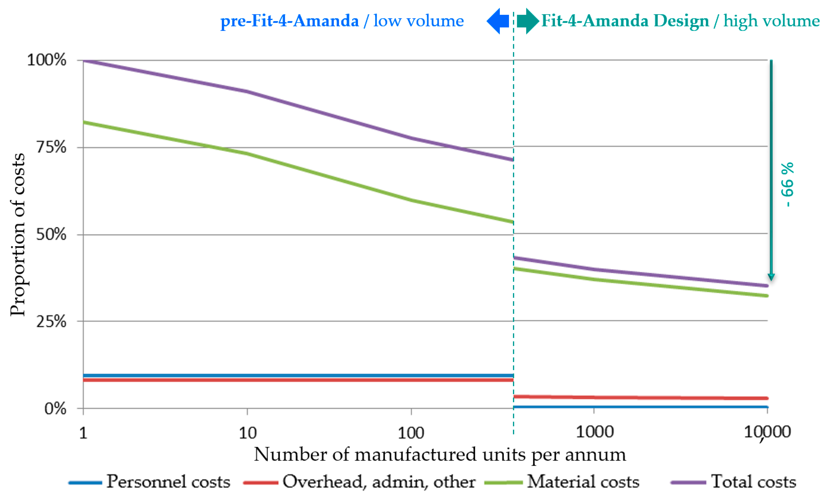
3.5. Transparency Concerning Economic and Technical Objectives

To highlight the economic and technical possibilities and to classify the objectives, the influence of an increased production rate was considered in combination with an increased degree of automation on production costs.
Boundary conditions therefore resulted from influencing criteria such as the number of stacks/a, production rate (stacks/h), labor costs, investments for machines and required equipment, and maintenance requirements. The maintenance costs were calculated as ~1.5% of capital expenditure/a. Different shift scenarios were be considered: one-, two- and three-shift operations with an efficiency of 80% of 240 d/a, with one working week comprising 40 working hours.
A comparison was conducted between the baseline (manual assembly of a 96 cell FC stack) and the achieved results (automated assembly of 96 cell FC stacks under different conditions). Different conditions mean manual production (as a baseline) in comparison to a modular production system for automated “seal-on components”. The manufacturing plant developed and presented here was designed for a maximum of 10,000 stacks/a in the current configuration. The following comparison between the previous manual stack assembly and the automated assembly of the “modular system seven-layer MEA” clearly demonstrated the cost-saving potential of automated assembly. The one-off investment costs for manual stack assembly were relatively low, while the wage cost rate for the considerations in Table 2/Figure 11 and Table 3/Figure 12 was defined as a constant parameter. The respective costs are presented in an arbitrary monetary unit (MU) without reference to a specific currency.
For this consideration, the investment costs of the plant and the corresponding personnel costs were divided between different numbers of units (scenarios). The graph shown in Figure 11 clearly shows that an increase in the number of stacks produced had little effect, i.e., no noticeable reduction, on production costs. Moreover, in the hypothetical scenario based on Table 2/Figure 11, with one full-time employee, it would take about 40 years in a single-shift operation to be able to produce a batch size of 10,000 stacks. Furthermore, the calculation in Table 2 allowed the derivation that with the assumed equipment costs, no significant cost savings were achieved by the theoretical increase of the production rate to over 1000. Based on this assumption, the value of 40 MU for a stack was used as a reference value for comparing the manual (Table 2/Figure 11) with the automated (Table 3/Figure 12) assembly.
The results shown in Table 3 and Figure 12 summarize that automation could reduce the cost of assembling the PEMFC stack to ~7% for 10,000 units per year, and to ~1% for 100,000 units per year compared to the cost of manual production. Table 4 compares the effects of the degree of automation on the production costs of the developed implementation variants for the automated stack assembly (especially the two MEA assembly variants) with the manual stack assembly.

4. Discussion

The need for rapid action to prevent further negative climate change is largely undisputed today, and mobility is responsible for a large proportion of climate-damaging emissions. Fuel cells offer a very promising solution, as they can be operated with dramatically reduced climate-damaging emissions, depending on the origin of the hydrogen used.
However in addition to the problems of an adequate hydrogen infrastructure that have not yet been solved, the high costs stand in the way of a wide use of fuel cells in the mobile sector. Above all, there is currently a great deal of interest and market potential in the area of motor traffic with fuel cell hybridized battery electric drives, from light commercial vehicles (LCV) in daily delivery traffic to municipal vehicles (e.g., garbage trucks) and local public transport buses. The required service life and performance requirements can be achieved by using a relatively small fuel cell to secure the base load in range extender operation in combination with a sufficient battery capacity (but also significantly smaller). Additionally, the cost targets could be achieved far earlier than would be possible with pure fuel cell drives or pure battery drives. In addition, the hydrogen infrastructure problem, especially in fleet operation, is significantly alleviated by the back-to-base application for these use cases. Furthermore, challenges caused by long battery charging times and a lack of charging infrastructure respective to charging capacity can also be avoided.
The cost situation of the fuel cell systems will be improved to a certain extent by the market ramp-up and the higher unit numbers based on the resulting economies of scale. However, a paradigm shift in the production method is necessary in order to move from the small series that have previously been produced manually to the mass production of medium volumes (the volumes considered here are still far away from passenger car OEM volumes). Special attention must be paid to ensure that production capacity grows in parallel to the expected unit numbers. Since the target market described above is currently served more by SMEs than by the major OEMs, different challenges are presented and approaches are necessary to overcome the market barriers that are going to govern the market beyond 2025.
This article specifically discussed some possible ways of reducing the manufacturing costs of the fuel cell stack as the heart of a fuel cell system. For example, by switching from manual production to automated stack production, it would be possible to produce several thousand stacks per year instead of a few hundred, while drastically reducing manufacturing costs per unit at the same time. In addition, the cost potential for the respective number of units can also be optimized by skillfully and carefully selecting a suitable stacking concept and redesigning the cell and stack for mass production by selecting the stacking concepts used. Further potential savings also arise from reduced material costs. The described automated machine concept is also highly flexible due to a high degree of modularization, so it could easily be adapted to the respective requirements of varied stack technologies or production targets by adding further modules.
Since fuel cell stacks are not limited to transport applications, but can also be used in portable and stationary applications, the cost savings potentially increase even further due to the additional sales volumes from other application fields.

5. Conclusions

The specifications drawn up within the framework of the Fit-4-AMandA project form the basis for the development regarding machine, process, stack, and components. For this purpose, the assembly process was divided into individual steps. Component supply, the subassemblies such as the single cell, the fuel cell stack assembly, and the interconnection of all steps in a mass production machine were identified. For each individual assembly step, a product-specific technology and functional unit was developed for its execution, with the exception of the CCM foil supply. This also required several changes in the product design.
A demonstrator machine was defined, designed, and manufactured for testing and verification of the essential technologies. All functional units required for the demonstration of an automatic fuel cell assembly process were integrated into this system at least once. Four main tasks were identified in the machine design process.
  • The development of process and functional units for component supply with the modules for GDL bottom, GDL top, CCM, the handling of the seal, and the MEA, as well as the finished MEA–seal assembly into the stacking boxes;
  • The development of process and functional units for MEA assembly, including the handling system, and grippers for the bipolar plates, the to-a-degree flexible porous GDL, and the ultra-thin CCM, followed by the vision system for component position detection for a precise position-corrected arrangement of the components one on top the other;
  • The development of process units and functional units for stack assembly with handling and grippers for the flexible MEA and surface-structured BPP, the stacking station, and the clamping station, with a suitable press for applying the appropriate stack compression;
  • The development of a process connection and testing machine system with the transfer system, which connects the modules from the loading point via the stacking station to the clamping station via a carrier suitable for stacking and transporting the unrestrained and strained stack.
Finally the production of the test machine was realized from the procurement and parts production via the mechanical and electrical assembly to the software development (programmable logic controller PLC, robot, vision system, and pluggable database PDB system) and commissioning of the machine.
All functional units were put into operation: component supply, vision systems, MEA assembly, BPP supply, handling robot, transfer system, stacking tower, and press unit. Their individual technologies and functional subunits were tested and iteratively optimized up to the system test with complete assembly technology in the interaction of all combined functions of all stations.
The theoretically achievable cost reduction of the PEMFC stack assembly was calculated based on the knowledge gained so far from plant design and implementation, and on the results of the necessary analyses and preliminary tests. In addition, further advantages could include the increase in productivity and the competence to automatically produce 10,000 units of 96 cells of PEMFC stacks in one year. This could be achieved, among other things, by considerably reducing the testing time (removing possible bottlenecks, see Section 3.2), the reject rate, and the revision expenditure, which in turn are based on the implementation of optimization measures regarding the components and the assembly of components and PEMFC stacks. An experimental validation is still pending and is expected during the next half year.

Author Contributions

Conceptualization, S.P.; Methodology, S.P., T.W. and T.R.; Validation, S.P., T.W. and T.R.; Investigation, S.P., T.W. and T.R.; Writing—original draft preparation, S.P.; Writing—review and editing, S.P., T.W. and T.R.; Supervision, S.P. and T.W.

Funding

This project has received funding from the Fuel Cells and Hydrogen 2 Joint Undertaking under grant agreement No 735606. This Joint Undertaking receives support from the European Union’s Horizon 2020 research and innovation programme and Hydrogen Europe and N.ERGHY.

Acknowledgments

The approaches and results of this article were achieved in the context of the EU project Fit-4-AMandA Grant Agreement number: 735606. The acronym stands for “Fit for Automatic Manufacturing and Assembly” of PEM FC stacks. Fit-4-AMandA focuses on the industrialization of stack components and stack assembly, and on delivering affordable fuel cell systems in larger quantities to saturate the emerging market demand. The Project Consortium consists of: Uniresearch B.V.; UPS Europe SA; Proton Motor Fuel Cell GmbH; Aumann Limbach-Oberfrohna GmbH; Fraunhofer IWU; Chemnitz University of Technology/ALF; IRD Fuel Cell A/S.

Conflicts of Interest

The authors declare no conflict of interest.

Abbreviations

The following abbreviations are used in this manuscript:
aAnnum, year
BPPBipolar plate
BOPBalance of plant
CCMCatalyst coated membrane
CO2Carbon Dioxide
EVElectric Vehicle(s), this means all vehicles that contain an electric traction motor such as EV, HEV, PHEV, BEV, FCEV, etc.
FCFuel cell
FCVfuel cell vehicles and cars
FCEVFuel Cell Electric Vehicle
FC REEVFuel Cell Range Extended Electric Vehicle
Fit-4-AMandAAcronym of the EU funded project: “Fit for Automatic Manufacturing and Assembly”
GDLGas Diffusion Layer
GmbHGesellschaft mit beschränkter Haftung (it is similar to the English Limited Company (Ltd.))
hHour
H2Chemical formula of molecular hydrogen
KPIKey Performance Indicator
MEAMembrane Electrode Assembly possibly consisting of 3, 5 or 7 layers
MMMMass Manufacturing Machine
MUMonetary Unit
OEM(Automotive) Original Equipment Manufacturer
PtPlatinum
PEMProton Exchange Membrane
PEMFCProton Exchange Membrane or Polymer Electrolyte Membrane Fuel Cells
Proton MotorProton Motor Fuel Cell GmbH, Germany Fuel Cell manufacturer
SMESmall and medium sized enterprise

References

  1. EU Targets 2030 Climate & Energy Framework. (Folder Path: European Commission → Energy, Climate Change, Environment → Climate Action → EU Action → Climate Strategies & Targets). Available online: https://ec.europa.eu/clima/policies/strategies/2030_en (accessed on 30 August 2019).
  2. Wannemacher, T.; (Proton Motor Fuel Cell GmbH). FCREEV—Fuel Cell Range Extended Vehicle. -e-Monday-. 20 December 2017, p. 31. Available online: http://docplayer.org/74266249-Fcreev-fuel-cell-range-extended-vehicle.html (accessed on 30 September 2019).
  3. Porstmann, S.; Scheffler, S.; Mainka, C.; (Fraunhofer Institute for Machine Tools and Forming Technology IWU). Analysis on the Supportive Technology for Optimized Manufacturability vs. Stack Performance. Deliverable 1.2 of the EU Project Fit-4-AMandA (EU Project, Duration 1 March 2017–28 February 2020, 36 Months). Funding Programme H2020-JTI-FCH-2016-1|Manufacturing Technologies for PEMFC Stack Components and Stacks, GA No 735606. Germany. 26 February 2018, pp. 1–19. Available online: https://fit-4-amanda.eu/downloads/ (accessed on 30 September 2019).
  4. James, B.D.; Huya-Kouadio, J.M.; Houchins, C.; (Strategic Analysis Inc.). Bipolar Plate Cost and Issues at High Production Rate (DOE Workshop on Research and Development Needs for Bipolar Plates for PEM Fuel Cell Technologies); Southfield, Michigan, USA. 14 February 2017. Available online: https://www.energy.gov/sites/prod/files/2017/05/f34/fcto_biploar_plates_wkshp_james.pdf (accessed on 10 September 2019).
  5. Elcore GmbH. How It’s Made Hydrogen Fuel Cells. Available online: https://www.youtube.com/watch?v=LDwS31OE7ak (accessed on 21 September 2019).
  6. TF Automation. Robotic Stack Assembly, A Final Assembly & Inspection Machine. Available online: https://www.youtube.com/watch?v=kIjsnGubDW8; https://tfautomation.co.uk/case-studies/robotic-stack/ (accessed on 21 September 2019).
  7. Gueble, J. Fuel Cell Assembly. Available online: https://www.youtube.com/watch?v=lLQAQEF36-U; https://www.jgueble.com/videos (accessed on 21 September 2019).
  8. James, B.D.; Huya-Kouadio, J.M.; Houchins, H.; DeSantis, D.A.; (Strategic Analysis Inc.). Mass Production Cost Estimation of Direct H2 PEM Fuel Cell Systems for Transportation Applications: 2017 Update, December 2017. Washington, DC, USA. Washington, DC, USA, December 2017; pp. 1–282. Available online: http://www.sainc.com/assets/site_18/files/publications/sa%202017%20transportation%20fuel%20cell%20cost%20analysis.pdf (accessed on 30 September 2019).
  9. Wilson, A.; Kleen, G.; Papageorgopoulos, D. DOE Hydrogen and Fuel Cells Program Record. Fuel Cell System Cost—2017. September 2017. Available online: https://www.hydrogen.energy.gov/pdfs/17007_fuel_cell_system_cost_2017.pdf (accessed on 10 September 2019).
  10. Thompson, S.T.; James, B.D.; Huya-Kouadio, J.M.; Houchins, C.; DeSantis, D.A.; Ahluwalia, R.; Wilson, A.R.; Kleen, G.; Papageorgopoulos, D. Direct Hydrogen Fuel Cell Electric Vehicle Cost Analysis: System and High-Volume Manufacturing Description, Validation, and Outlook. J. Power Sources 2018, 399, 301–313. Available online: https://doi.org/10.1016/j.jpowsour.2018.07.100 (accessed on 10 September 2019).
  11. James, B.D.; (Strategic Analysis Inc.). 2018 Cost Projections of PEM Fuel Cell Systems for Automobiles and Medium-Duty Vehicles. Fuel Cell Technologies Office Webinar on 25 April 2018. Available online: https://www.energy.gov/sites/prod/files/2018/04/f51/fcto_webinarslides_2018_costs_pem_fc_autos_trucks_042518.pdf (accessed on 10 September 2019).
  12. DigiMan (EU Project, Duration 1 January 2017–31 December 2019, 36 Months). Funded by FCH2 JU, DIGItal MAterials CharacterizatioN Proof-of-Process Auto Assembly, GA No 736290. Available online: https://cordis.europa.eu/project/rcn/207241/factsheet/en (accessed on 5 September 2019).
  13. PROFACTOR: Inline (EU Project, Duration 1 February 2017–31 January 2020, 36 Months). Funding Programme H2020-JTI-FCH-2016-1|An Innovative Design of a Flexible, Scalable, High Quality Production Line for PEMFC Manufacturing, GA No 735367. Available online: https://cordis.europa.eu/project/rcn/207238/reporting/en (accessed on 5 September 2019).
  14. Haberl, F.; (PowerCell Sweden, AB). Public Results of the Architecture and System Level Optimization, Deliverable 1.4 of the EU Project INN-BALANCE (Duration 1 January 2017–31 December 2019, 36 Months). Funding Programme H2020-JTI-FCH-2016-1|Development of Industrialization-Ready PEMFC Systems and System Components, GA No 735969. Sweden. 31 December 2017, pp. 1–11. Available online: https://www.innbalance-fch-project.eu/fileadmin/user_upload/downloads/D1.4_submitted.pdf (accessed on 5 September 2019).
  15. MAMA-MEA (EU Project, Duration 01 January 2018–31 December 2020, 36 Months). Funding Programme H2020-JTI-FCH-2017-1|Mass Manufacture of MEAs Using High Speed Deposition Processes, GA No 779591. Available online: https://www.mama-mea.eu/ (accessed on 5 September 2019).
  16. VolumetriQ (EU Project, Duration 01 September 2015–28 February 2019, 36 Months). Funding Programme H2020-JTI-FCH-2014-1|Volume Manufacturing of PEM FC Stacks for Transportation and In-line Quality Assurance, GA No 671465. Available online: http://www.volumetriq.eu/ (accessed on 5 September 2019). [CrossRef]
  17. AutoStack CORE (EU Project, Duration 1 May 2013–31 July 2017, 36 Months). Funding Programme H2020-JTI-FCH-2016-1|Automotive Fuel Cell Stack Cluster Initiative for Europe II, GA No 325335. Available online: https://www.zsw-bw.de/fileadmin/user_upload/PDFs/Forschung/ASC-Project_04.2016_screen.pdf (accessed on 5 September 2019).
  18. Autostack Industrie (NOW GmbH Project, Duration 1 June 2017–30 September 2019, 48 Months). Entwicklung von Montagetechnologie und Automatisierungskonzepten für Die Fertigung von Brennstoffzellen. Funding under the NIP Programme Supported by Participating Federal Ministries e.g. BMVI. (In Proceedings of the Supplier Workshop, Frankfurt, Germany, 26 July 2018). Available online: https://www.now-gmbh.de/content/1-aktuelles/1-presse/20180626-deutsche-automobil-und-zulieferindustrie-im-dialog-fuer-die-skalierung-von-automobilen-brennstoffzellen/asi-workshop_entwicklung-fertigung-stack_martin.pdf (accessed on 5 September 2019).
  19. MontaBS (NOW GmbH Project, Duration 1 January 2015–31 December 2016, 24 Months). Entwicklung von Montagetechnologie und Automatisierungskonzepten für Die Fertigung von Brennstoffzellenstacks. Funding Programme Funding under the NIP Programme Supported by Participating Federal Ministries e.g. BMVI. Available online: https://www.now-gmbh.de/en/national-innovation-programme/projektfinder/verkehr/montabs (accessed on 5 September 2019).
  20. Kraft, J.; Elring Klinger. PEMFC Technology; Stack Manufacturing Processes and Quality Techniques; PEMFC Stack and MEA Manufacturing Workshop. Workshop on 11 October 2018 in Brussels. Available online: https://www.fch.europa.eu/sites/default/files/PEMFC%20Technology%3B%20Stack%20manufacturing%20processes%20and%20quality%20techniques%20-%20Kraft%20%28ID%204826307%29.pdf (accessed on 5 September 2019).
  21. Baraldi, E.C.; Kaminski, P.C. Reference Model for the Implementation of New Assembly Processes in the Automotive Sector. Cogent Eng. 2018, 1–27. [Google Scholar] [CrossRef]
  22. Shaik, A.M.; Rao, V.V.S.K.; Rao, C.S. Development of Modular Manufacturing Systems—A Review; Springer: London, UK, 2014; pp. 789–802. Available online: https://link.springer.com/content/pdf/10.1007%2Fs00170-014-6289-2.pdf (accessed on 5 September 2019).
  23. Shahi, V.J.; Masoumi, A.; Franciosa, P.; Ceglarek, D. A Quality-Driven Assembly Sequence Planning and Line Configuration Selection for Non-Ideal Compliant Structures Assemblie; Springer London Ltd.: London, UK, 2019; Available online: https://doi.org/10.1007/s00170-019-04294-w (accessed on 5 September 2019).
  24. Richter, T.; Aumann Limbach-Oberfrohna GmbH. Aiming for Scalability and Efficiency, Automated Production and Assembly of Fuel Cells, Autoland Saxony. 2018, pp. 18–19. Available online: https://docplayer.org/112058005-Autoland-sachsen-autoland-saxony.html; https://www.autoland-sachsen.com/skalierbarkeit-und-effizienz-im-visier/ (accessed on 5 September 2019).
  25. Wittstock, R.; Pehlken, P.; Wark, M. Challenges in Automotive Fuel Cells Recycling. Article in MDPI Journal Recycling. 1 December 2016. Available online: https://www.mdpi.com/2313-4321/1/3/343/htm (accessed on 22 September 2019).
Figure 1. Polymer electrolyte membrane fuel cell (PEMFC) vehicle components and hierarchy (a) and PEMFC stack of Proton Motor (b) based on [3].
Machines 07 00066 g001
Figure 2. Production rate dependent reduction potential of component costs of PEMFC stacks starting from 1000 units/a based on [4,9].
Machines 07 00066 g002
Figure 3. Production rate dependent reduction potential of manufacturing costs of PEMFC stacks starting from 1000 units/a based on [4,9].
Machines 07 00066 g003
Figure 4. Breakdown of the 2017 projected PEMFC stack cost at 1000, 10,000, 100,000, and 500,000 units/a based on [4,9].
Machines 07 00066 g004
Figure 5. Device for restraining the PEMFC stacks as part of the automated assembly line (a) and PEMFC stack of Proton Motor (b).
Machines 07 00066 g005
Figure 6. Schematic of the stack assembly process.
Machines 07 00066 g006
Figure 7. Schematic illustration of the modular mass manufacturing machine (MMM) as it is currently built (expansion stage 1).
Machines 07 00066 g007
Figure 8. 3D-CAD layout of the plant for automated production and assembly of PEMFC stacks based on [24].
Machines 07 00066 g008
Figure 9. Schematic illustration of the modular MMM in an expanded form (* = expansion stage 2). VIS = high performance (visual) inspection systems; FAT = factory acceptance test.
Machines 07 00066 g009
Figure 10. Prospects for stack manufacturing costs for higher volumes.
Machines 07 00066 g010
Figure 11. Baseline—manual assembly—production time 40 h/stack with 1 operator.
Machines 07 00066 g011
Figure 12. Developed mass manufacturing machine (MMM)—automated assembly of the “modular system seven-layer membrane electrode assembly (MEA)”—production time 10 min/stack with one operator.
Machines 07 00066 g012
Table 1. Overview of the key performance indicators for PEMFC stacks.
Key Performance Indicators (KPIs) BaselineTargets
Single stack production time (throughput time)40 h<0.5 h
Automated production process steps 10% automation grade per stack90% automation grade per stack
Testing time (automated and manually)24 h1 h
Costs per stack100%<50%
Reduction of scrap (e.g., broken bipolar plates per stack during production)10 per stack0
Unaccepted tests: rework and unbundling of stackEvery 10th stack needs to be reworked0
Tightness and leakage of the stack (reworking frequency due to failed tightness or sealing tests)Every 10th stack needs to be reworked0
Table 2. Baseline—manual assembly—production time 40 h/stack with one operator.
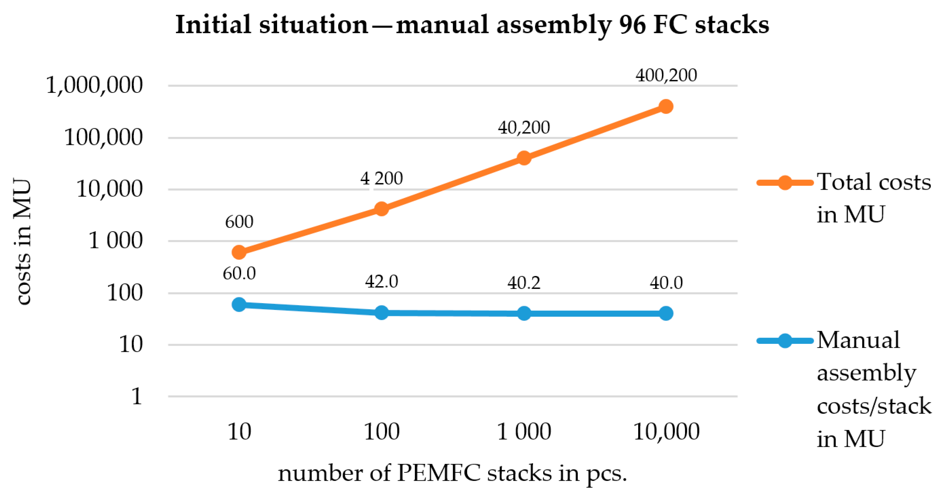
Initial Situation–Manual Assembly 96 FC Stacks
Number of Stacks in pcs.
Input10100100010,000100,000
Investment for equipment in MU
200200200200200
Labor costs in sum in MU
400400040,000400,0004,000,000
Total costs in MU
600420040,200400,2004,000,200
OutputManual assembly costs/stack in MU
60.042.040.240.040.0
100.0%70.0%67.0%66.7%66.7%
Table 3. Developed MMM—automated assembly of the “modular system seven-layer MEA”—production time 10 min/stack with one operator.
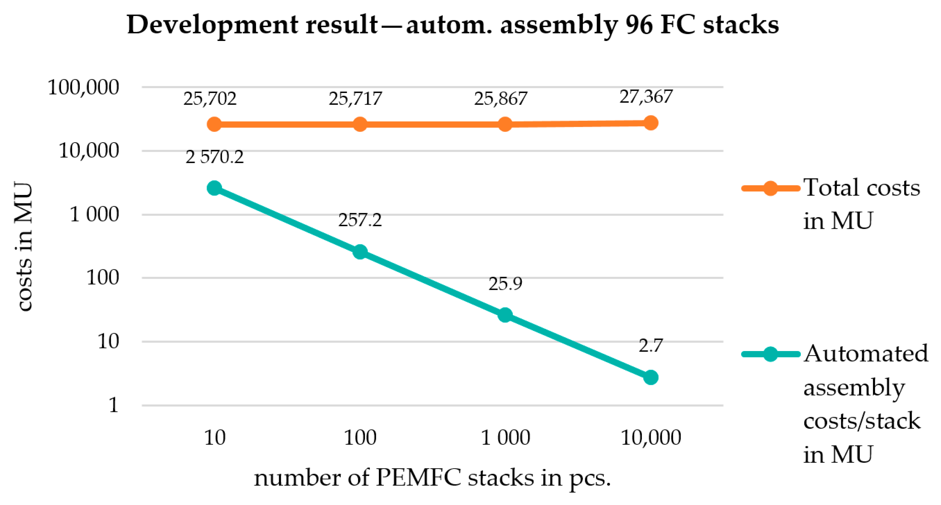
Development Result–Autom. Assembly 96 FC Stacks
Number of Stacks in pcs.
Input10100100010,000100,000
Investment for equipment in MU
25,70025,70025,70025,70025,700
Labor costs in sum in MU
1.716.7166.71666.716,666,7
Total costs in MU
25,70225,71725,86727,36742,367
OutputAutomated assembly costs/stack in MU
2570.2257.225.92.70.4
100.00%10.01%1.01%0.11%0.02%
Ratio ‘autom. assembly/manual assembly 40 MU’ (costs/stack)
6422.21%642.60%64.63%6.84%1.06%
Table 4. Comparison of different automated stack assembly variants.
Key Performance Indicators (KPIs)BaselineTargetModular System Seal on MEAModular System Seven-Layer-MEA
Cycle time for 96 cells40 h0.5 h~0.15 h~0.15 h
Degree of automation0.10%90%~95%~95%
Reduction of scrap10%<0.5%Proof pendingProof pending
First pass yield90%99%Proof pendingProof pending
Assembly costs of 10,000 stacks100%<50%~12%~7%

