Article

Analysis of Sound Insulation Performance in Aeronautical Composite Materials and Optimization Study on Film Metamaterials


1
AVIC The First Aircraft Institute, Xi’an 710089, China
2
National Key Laboratory of Aircraft Configuration Design, Northwestern Polytechnical University, Xi’an 710072, China
*
Author to whom correspondence should be addressed.
Machines 2026, 14(9), 1042; https://doi.org/10.3390/machines14091042
Submission received: 31 July 2026 / Revised: 29 August 2026 / Accepted: 7 September 2026 / Published: 14 September 2026

Abstract

The adoption of carbon fiber-reinforced polymer (CFRP) composites in aircraft structures has significantly reduced structural weight but compromised mid-frequency sound insulation performance. To address this issue, this study develops a lightweight membrane-type acoustic metamaterial design targeting the 2000 Hz sound insulation valley of aeronautical composite panels. An impedance tube test platform was constructed to characterize the full-frequency sound transmission loss (STL) of CFRP specimens, and a structure–acoustic coupled finite element model incorporating equivalent boundary stiffness was established and validated. The mean absolute error (MAE) of the simulation above 1000 Hz is within 3 dB, with a maximum single-point error of 3.9 dB, satisfying the engineering accuracy requirement for most frequency points. Under the constraint of no more than 5% weight increase, a forward-design methodology for membrane metamaterials is proposed based on modal analysis and local resonance tuning. Experimental results show that the proposed design achieves a 16.5 dB STL enhancement at 2000 Hz with a 2.29% weight increase under normal incidence conditions at the unit-cell level, exceeding the 3 dB technical requirement. This work provides a practical engineering reference for lightweight mid-frequency noise control in aircraft cabin applications.

1. Introduction

Amid global efforts toward carbon neutrality, the aviation industry is actively pursuing structural lightweighting as a core strategy. The International Civil Aviation Organization (ICAO) has established a target of carbon-neutral growth for international aviation from 2020 onward. Leading aerospace manufacturers, including Airbus and Mitsubishi Heavy Industries, have identified large-scale adoption of composite materials as a core technical route to reduce structural weight, improve fuel efficiency, and enhance overall aircraft performance [1]. However, structural lightweighting introduces new challenges in cabin noise control. During cruise flight, cabin noise originates primarily from turbulent boundary layer pressure fluctuations, engine noise radiation, and equipment-borne vibrations, covering a broad frequency spectrum from 50 Hz to 8000 Hz. Low- to mid-frequency components below 2000 Hz show strong transmissibility with limited natural attenuation, representing the dominant contributor to passenger discomfort. Conventional aluminum alloy panels rely on relatively high area density to provide adequate low- to mid-frequency sound insulation. Carbon fiber-reinforced polymer (CFRP) composites, by contrast, have significantly lower area density and show anisotropic mechanical properties, resulting in acoustic behavior markedly different from that of homogeneous metallic structures. This discrepancy exacerbates the sound insulation deficiency in the low- to mid-frequency range. Traditional countermeasures such as adding mass or sound-absorptive materials would directly offset the benefits of lightweight design. According to the mass law, sound transmission loss improves by approximately 6 dB per doubling of area density, implying that enhancing low-frequency insulation through mass addition is highly inefficient and incompatible with aviation lightweight requirements. Alternative approaches, including damping treatments, porous absorption, and resonant structures, still suffer from limitations such as insufficient low-frequency performance and excessive space requirements [2].
In recent years, acoustic metamaterials have emerged as a promising technology for low-frequency sound insulation. In 2008, Yang et al. first proposed a membrane-type acoustic metamaterial consisting of a prestressed membrane loaded with concentrated proof masses [3]. This configuration exploits the anti-resonance coupling between the membrane and the masses, generating a distinct insulation peak between two adjacent resonance frequencies. The underlying mechanism involves negative dynamic mass density within the structure, which induces total wave reflection and enables significant low-frequency sound insulation with minimal added weight. Naify et al. further investigated the transmission loss and dynamic response characteristics of membrane-type locally resonant metamaterials, establishing systematic analytical models for their acoustic behavior [4,5].
Subsequent studies have further explored the sound insulation characteristics of membrane metamaterials. Zhang studied the effects of membrane parameters and mass configurations on sound insulation performance and established equivalent analysis models. Wu et al. provided a systematic review of the sound insulation mechanisms of membrane-type acoustic metamaterials, summarizing advances in structural design and performance optimization [6,7,8,9].
  • In the aerospace field, researchers have begun exploring metamaterial-based solutions for aircraft cabin noise reduction. Wang conducted a systematic study on lightweight acoustic metamaterial design for aircraft cabin noise control, analyzing the engineering constraints and performance requirements of aeronautical applications. Several studies investigated the sound insulation improvement of composite panels embedded with membrane metamaterials, validating the effectiveness of the integration scheme through experimental testing [10,11,12,13,14].
  • Despite these advances, several critical gaps remain in the current literature. First, most existing studies focus on low-frequency applications below 1000 Hz, whereas the 2000 Hz mid-frequency range, which is particularly relevant to turbulent boundary layer noise in aircraft cabins, has received limited attention. Second, many proposed configurations rely on custom-fabricated membranes and complex assembly processes, hindering their practical deployment in industrial settings. Third, systematic design methodologies for membrane metamaterials targeting specific frequency valleys under strict lightweight constraints remain underdeveloped. Addressing these gaps is essential for translating membrane metamaterial technology from laboratory demonstrations to practical aeronautical applications [15,16,17].
  • This study addresses the lightweight sound insulation challenges of aeronautical CFRP structures through a systematic investigation encompassing component-level testing, numerical modeling, forward metamaterial design, and experimental validation. The main contributions are summarized as follows:
  • A forward-design methodology for membrane-type acoustic metamaterials targeting the 2000 Hz sound insulation valley of aeronautical composite panels is established under strict lightweight constraints (≤5% weight increase), providing an engineering-oriented design flow directly applicable to aircraft cabin noise reduction scenarios [10,11,12].
Compared with existing membrane-type metamaterial studies that primarily focus on low-frequency applications below 1000 Hz and often rely on custom-fabricated membranes, the present work targets the 2000 Hz mid-frequency range relevant to aircraft cabin turbulent boundary layer noise and uses commercially available standard PET film (150 μm) with mature die-cutting and bonding processes.

2. Theoretical Foundation

2.1. Plane Wave Propagation and Interface Transmission

The schematic diagram of sound transmission through a single-layer fiber-reinforced composite laminate is shown in Figure 1, which illustrates the sound transmission mechanism of a single-layer panel. Assuming the plate is infinitely large and homogeneous, a plane pressure wave propagates through the single-layer panel from the external side. The angle between the incident pressure wave and the normal axis is denoted as φ 1 , while the angle between the incident pressure wave and the x-axis is θ . Similarly, for the transmitted wave, the angles with respect to the normal axis and the x-axis are θ t and φ t , respectively. The density and sound speed of the fluid medium on the incident side are denoted as ρ i and c i , respectively, while those on the transmitted side are ρ t and c t .
The pressure waves on the incident side satisfy the wave equation.
c i 2 2 ( p i + p r ) 2 ( p i + p r ) t 2 = 0
In this context, p i and p r respectively denote the incident wave and reflected wave. On the transmitted side, the transmitted wave satisfies the wave equation:
c t 2 2 p t 2 p t t 2 = 0
In this context, c t represents the sound propagation speed on the transmitted side, and p t denotes the transmitted wave.
The equation of motion for the single-layer fiber-reinforced composite laminate is given by
L 11 L 12 L 13 L 21 L 22 L 23 L 31 L 32 L 33 u 1 v 1 w 1 + I 1 0 0 0 I 1 0 0 0 I 1 2 t 2 u 1 v 1 w 1 = 0 0 ( p i + p r ) p t
In this context, u 1 , v 1 , w 1 represent the displacement components of the single-layer fiber-reinforced composite laminate in the x, y, and z directions, respectively. The operator L i j denotes the differential operator, while I 1 represents the inertial term of the single-layer fiber-reinforced composite laminate.
At the interface, the single-layer panel must satisfy the following boundary conditions [18]:
( p i + p r ) z = ρ 1 2 w 1 t 2 z = 0
p t z = ρ t 2 w 1 t 2 z = H
where H represents the thickness of the composite laminate.
The incident pressure wave can be expressed as a harmonic function in terms of time and space:
p i = P i e i k 1 x x + k 1 y y + k 1 z z
where P i is the amplitude; the wave number of the incident wave can be expressed as k 1 = ω / c i , and the components of the wave number in different directions are given by
k 1 x = k 1 sin φ 1 cos θ k 1 y = k 1 sin φ 1 sin θ k 1 z 2 = k 1 2 k 1 x 2 + k 1 y 2
On the transmitted side, the corresponding wave number can be expressed as k 2 = ω / c t , and the components of the wave number in different directions are given by
k 2 x = k 1 x k 2 y = k 1 y k 2 z 2 = k 2 2 k 2 x 2 + k 2 y 2
To satisfy Equations (1)–(3), p r , p t , u 1 , v 1 , w 1 can be expressed as
p r = P r e i k 1 x x + k 1 y y k 1 z z p t = P t e i k 2 x x + k 2 y y + k 2 z z u 1 = U 1 e i k 1 x x + k 1 y y v 1 = V 1 e i k 1 x x + k 1 y y w 1 = W 1 e i k 1 x x + k 1 y y
Substituting the above expressions into the equations of motion and boundary condition equations for single-layer fiber-reinforced composite laminates yields five algebraic equations. When the incident wave amplitude P i is known, these algebraic equations can be used to solve for the unknowns p r , p t , u 1 , v 1 , w 1 .
When a sound wave is obliquely incident on the upper surface of a plate, the ratio of the transmitted wave’s acoustic intensity to the incident wave’s acoustic intensity (i.e., the acoustic intensity transmission coefficient) τ can be expressed as
τ = I transmitted I incident = | P t | 2 / ( 2 ρ 2 c 2 ) | P i | 2 / ( 2 ρ 1 c 1 ) = 4 ρ 1 c 1 ρ 2 c 2 cos θ cos θ t ( ρ 2 c 2 cos θ + ρ 1 c 1 cos θ t ) 2
The average sound intensity transmission coefficient τ ¯ can be expressed as
τ ¯ = θ = 0 2 π φ 1 = 0 φ m τ sin φ 1 cos φ 1 d φ 1 d θ θ = 0 2 π φ 1 = 0 φ m sin φ 1 cos φ 1 d φ 1 d θ
where φ m denotes the limiting angle assumed when no acoustic wave is received, and it is taken as 78° when there is no external flow.
Therefore, the random incidence sound transmission loss of the panel can be defined as
TL = 10 lg 1 τ ¯

2.2. Mass Law for Sound Insulation

For a homogeneous dense thin plate, in mid-to-high frequencies and neglecting stiffness and damping effects, the sound insulation follows the classical mass law.
T L = 20 log 10 m + 20 log 10 f 20 log 10 ρ 0 c / π
In the formula, f represents the frequency of the incident sound wave (Hz); m denotes the surface density of the structure (kg/m2); and ρ 0 is the air density (kg/m3). Under standard temperature and pressure conditions, ( ρ 0 c 415   Pa · s / m ), and substituting this value into the equation simplifies it to a commonly used form in engineering applications.
T L = 20 log 10 m + 20 log 10 f 42
At this point, the sound transmission loss is primarily determined by the surface density of the partition and is independent of its stiffness and damping. The greater the surface density, the higher the sound transmission loss, resulting in better sound insulation performance. When the surface density doubles, the sound insulation increases by a specific amount, which follows the commonly used mass law. The mass law reveals the fundamental limitation of traditional sound-insulating structures: the sound insulation is proportional to the logarithm of both frequency and surface density. To improve low-frequency sound insulation, it is necessary to significantly increase the structural mass, which comes at the cost of adding significant weight. This is also the root cause behind the degraded low-frequency sound insulation performance in lightweight composite material panels.

2.3. Structure–Acoustic Coupling Finite Element Method

The sound insulation process of thin plate structures is essentially a bidirectional coupling between structural vibrations and the acoustic field: incident sound waves apply acoustic pressure excitation, inducing structural vibrations, which in turn radiate sound energy to the transmitted side. When solving using the finite element method, the coupled system is formed by combining the equations of structural dynamics with the Helmholtz equation for acoustics [19,20,21].
Structural Domain Governing Equation:
M s u · · + C s u · + K s u = F s + F f
In the equations, M s denotes the structural mass matrix; C s denotes the structural damping matrix; K s denotes the structural stiffness matrix; F f denotes the reaction force vector from the acoustic field; and F s denotes the external load vector on the structure.
Acoustic Domain Governing Equation:
M a p · · + C a p · + K a p = F a
In the equations: M a denotes the acoustic mass matrix; C a denotes the acoustic damping matrix; K a denotes the acoustic stiffness matrix; F a denotes the acoustic load vector; and p denotes the sound pressure vector.
The finite element matrix equations for the acoustic–structure coupling system are defined as follows:
M s 0 ρ A T M a u · · p · · + C s 0 0 C a u · p · + K s A 0 K a u p = F s 0
By coupling the degrees of freedom between the two physical fields through the interface, the sound pressure distribution on the transmitted side can be solved for, and subsequently, the sound transmission loss of the structure can be calculated.

2.4. Sound Insulation Mechanism of Membrane-Type Acoustic Metamaterials

The core mechanism by which membrane-type acoustic metamaterials overcome the mass law limitation relies on anti-resonance effects and negative dynamic mass.
M e f f ω = m s + m m ω 2 0 ω 2 0 ω 2
where m s is the equivalent mass corresponding to the film’s surface density, and m m is the mass of the attached concentrated mass block. The system’s natural frequency is denoted by ω 0 . When the excitation frequency approaches and slightly exceeds the natural frequency, the overall dynamic mass M e f f ω becomes less than zero. At this point, the motion direction of the mass block is opposite to that of the film, causing the structure to show rigid reflective characteristics towards the incident wave. This results in a significant sound insulation peak.
The anti-resonant frequency is determined by the film tension T , surface density of the film ρ s , mass of the attached mass block m m , and its dimensions [22,23,24]. It can be approximated by the following expression:
f a n t u = 1 2 π 8 π T m m ln R / a
where R is the radius of the film unit, and a is the radius of the mass block. By adjusting parameters such as film tension, surface density, mass block mass, and dimensions, the sound insulation peak can be precisely controlled to target frequency bands. Since the sound insulation effect of the film-type acoustic metamaterial does not depend on the overall surface density of the structure, excellent low-frequency sound insulation performance can be achieved with minimal weight penalty [18,25].

3. Numerical Modeling and Experimental Scheme

3.1. Basic Parameters of the Research Object

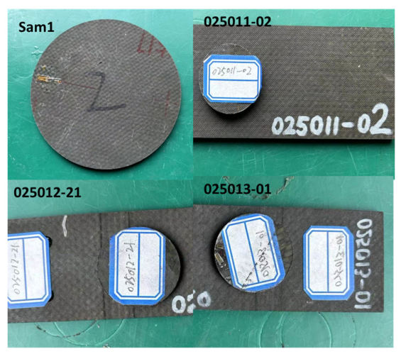
In this study, a total of four carbon fiber composite material component-level specimens were prepared, covering two material systems, three thicknesses, and multiple layup methods. The specific parameters are shown in Table 1. The specimens were fabricated using the autoclave curing process, with layup angles including 0°, 45°, corresponding to different structural stiffness and surface densities. Among them, Sam1 is a large-size specimen of 100 mm, compatible with the CIT100 impedance tube; the other three are small-size specimens of 30 mm, compatible with the CIT30 impedance tube. The actual photos of the four specimens are shown in Figure 2.
Two types of composite material systems show orthotropic anisotropic mechanical properties, as shown in Table 2. Due to the anisotropic nature of composite materials’ mechanical performance, the tensile modulus can vary by an order of magnitude across different layup angles. This directly results in significant differences in sound insulation characteristics among specimens with varying layups [26,27].
The mesh consists of hexahedral acoustic elements with a maximum element size of 5 mm, to ensure at least 6 elements per wavelength at the maximum analysis frequency of 8000 Hz. The composite specimen is meshed with quadrilateral shell elements with an element size of 2 mm.

3.2. Finite Element Modeling

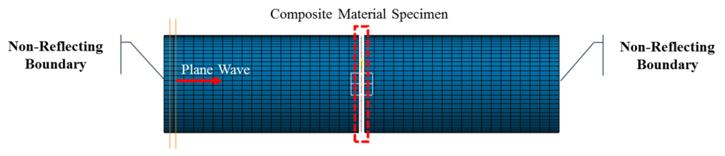
Using LMS Virtual.Lab acoustic simulation software((Version 13.3) to establish an impedance tube-specimen coupled finite element model, the model consists of three parts: incident acoustic cavity, transmitted acoustic cavity, and composite material specimen. The incident segment is set with plane wave incidence as the boundary condition. Both ends are defined as non-reflecting boundaries to simulate an infinitely long duct. The two sides of the film are coupled with corresponding faces of the acoustic tube, defining the structural and air coupling characteristics. For a detailed visualization of the model, refer to Figure 3.
The model incorporates the following key aspects:
  • The incident cavity and transmitted cavity are both meshed with hexahedral acoustic elements, with element sizes satisfying the precision requirement of at least six elements per wavelength under the maximum analysis frequency. The composite material specimen is modeled using quadrilateral shell elements to accurately simulate its structural behavior. The individual layers of the composite are defined through a composite material layup tool, specifying each layer’s orientation angle and material properties. This approach ensures precise representation of the orthotropic anisotropic characteristics inherent in the composite structure.
  • To account for the boundary conditions, a ring of equivalent rubber layer is modeled along the edges of the specimen in contact with the fixture. Constrain the translational degrees of freedom (DOFs) in the X, Y, and Z directions of the outer ring nodes of the equivalent rubber layer, and release the rotational degrees of freedom. By adjusting the stiffness of this rubber layer, the sound insulation curve is matched, avoiding the use of idealized fixed boundary conditions and more realistically capturing the interaction between the specimen and its mounting setup, thus improving the accuracy of low-frequency simulation results. The parameters of the equivalent rubber ring are shown in Table 3. The equivalent rubber layer parameters were determined through inverse calibration by adjusting the rubber layer stiffness to match the low-frequency sound transmission loss curve of the bare composite specimen. The significant difference in Young’s modulus between the CIT100 (75,000 MPa) and CIT30 (11 MPa) fixtures reflects their different clamping stiffness. Note that the Young’s moduli in Table 3 are equivalent, inverse-calibrated boundary stiffnesses rather than the true material moduli of the rubber; the very large CIT100 value reflects the near-rigid bolted flange rather than the rubber itself.
  • On the upper and lower surfaces of the specimen, structural-acoustic coupling interfaces are defined to establish a connection between the structural and acoustic domains. Each structural node is carefully matched with its corresponding acoustic node, to ensure precise bidirectional interaction between structural vibrations and the acoustic field.

3.3. Impedance Tube Test System

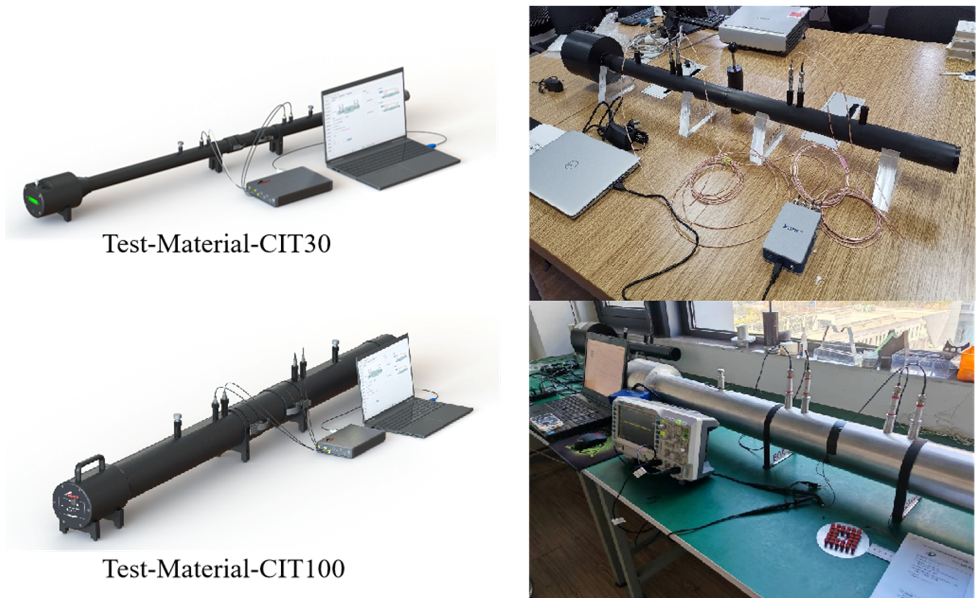
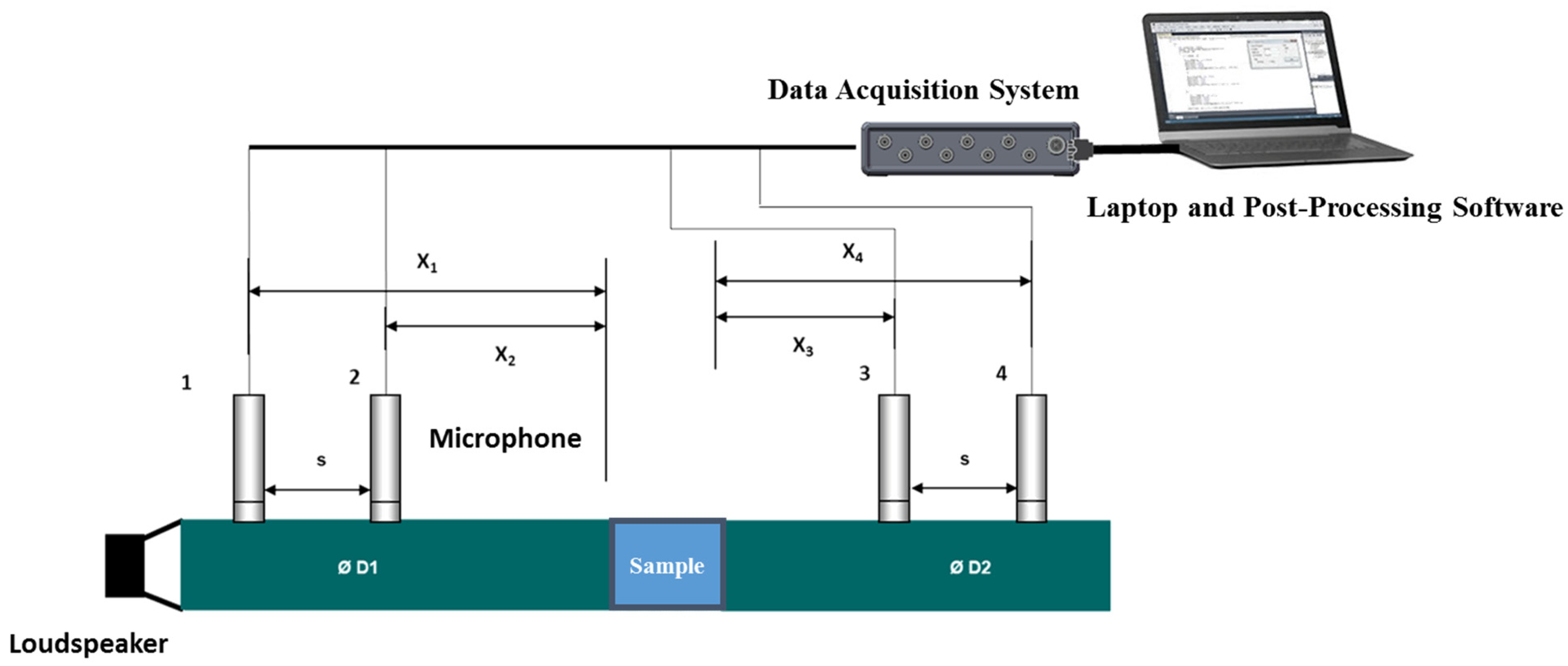
Sound insulation tests were carried out using the BOACH Test-Material-CIT series circular impedance tube system (Suzhou BAOCH Acoustic Technology Co., Ltd., Suzhou, China; Figure 4), following the transfer function method specified in the GB/Z 27764-2011 [28] standard for normal incidence sound transmission loss measurements. The system primarily consists of a sound source section, incident section, specimen fixture, transmitted section, and anechoic termination. It is complemented by 1/4-inch microphones and a multi-channel acoustic analysis system to ensure precise and comprehensive testing procedures [29], as illustrated in Figure 5.
CIT100 Impedance Tube: Inner diameter of 100 mm, effective test frequency range from 100 Hz to 6300 Hz, designed for mid-to-low frequency testing of large-sized specimens.
CIT30 Impedance Tube: Inner diameter of 30 mm, effective test frequency range from 800 Hz to 8000 Hz, suitable for mid-to-high-frequency testing of small-sized specimens.
The test environment is a laboratory with ambient temperature and pressure, where the environmental background noise level is below 30 dB(A). Before testing, the microphones are calibrated for phase matching. During the test, it is ensured that the specimen is properly sealed with the fixture to avoid acoustic leakage, which could lead to lower test results. Each specimen is tested three times, and the average value is taken as the final result to ensure data repeatability.
During testing, specimens were carefully installed to prevent gaps caused by cutting or other factors. Sealant putty was applied to any gaps between the specimen and the impedance tube wall to ensure an airtight seal.

4. Analysis of Sound Insulation Performance and Model Validation

4.1. Analysis of Sound Insulation Characteristics for Composite Material Specimens

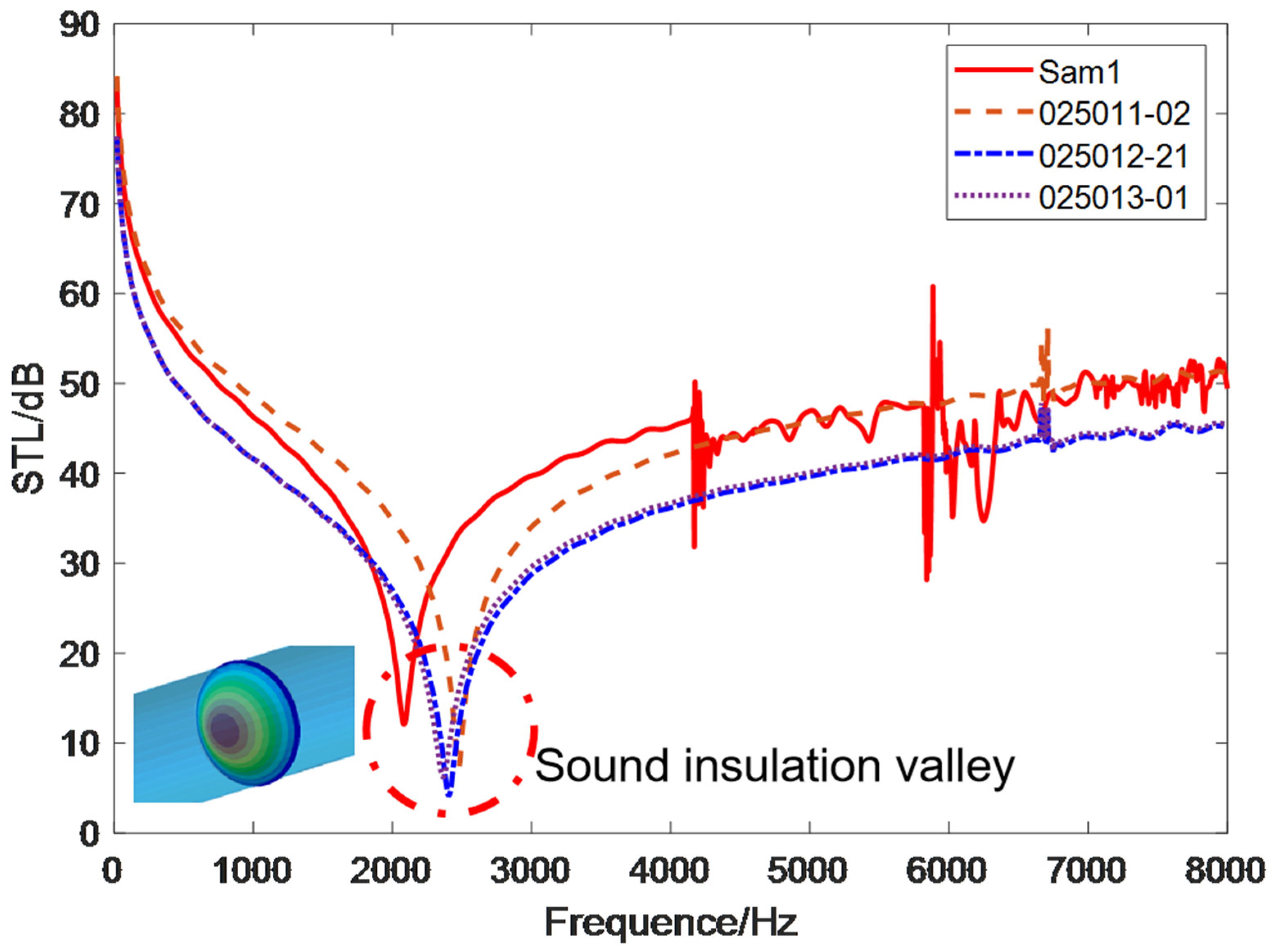
The sound insulation simulation results for the four specimens are presented in Figure 6. All specimens show typical thin-plate sound insulation behavior, characterized by a low-frequency stiffness-controlled region and a mid-frequency mass-controlled region, with the boundary defined by the frequency corresponding to the first-order drum mode.
When the composite material component-level specimens are under drum-type mode conditions, the entire structure moves in one direction, resulting in minimal sound insulation.
In the low-frequency stiffness-controlled region, the sound insulation level decreases as frequency increases, primarily dominated by structural stiffness. Higher stiffness results in better low-frequency sound insulation performance.
In the mid-frequency mass-controlled region, the sound insulation level generally increases with rising frequency, in accordance with the mass law. However, due to the influence of structural modal resonance, the curve shows significant fluctuations.
Within the same material system (AC531/CF8611), the thicker specimens (3.96 mm, with more plies and higher area density) exhibit higher overall sound insulation than the thinner specimen (1.76 mm). Sam1 and 025011-02, however, share the same material system, layup, and thickness (3.96 mm) and differ only in specimen diameter and fixture (100 mm in the CIT100 versus 30 mm in the CIT30); the slight difference between their curves is therefore attributable to specimen size and the mounting boundary rather than to the layup, which is consistent with the boundary-stiffness coupling analyzed in Section 4.2. Conversely, 025012-21 and 025013-01 adopt the same layup and close thicknesses (1.76 versus 1.84 mm) but different material systems, yet their mid-to-high-frequency responses remain close. Overall, the mid-to-high-frequency sound insulation is governed primarily by area density and depends only weakly on the material system and the layup.

4.2. Experimental Comparison Verification

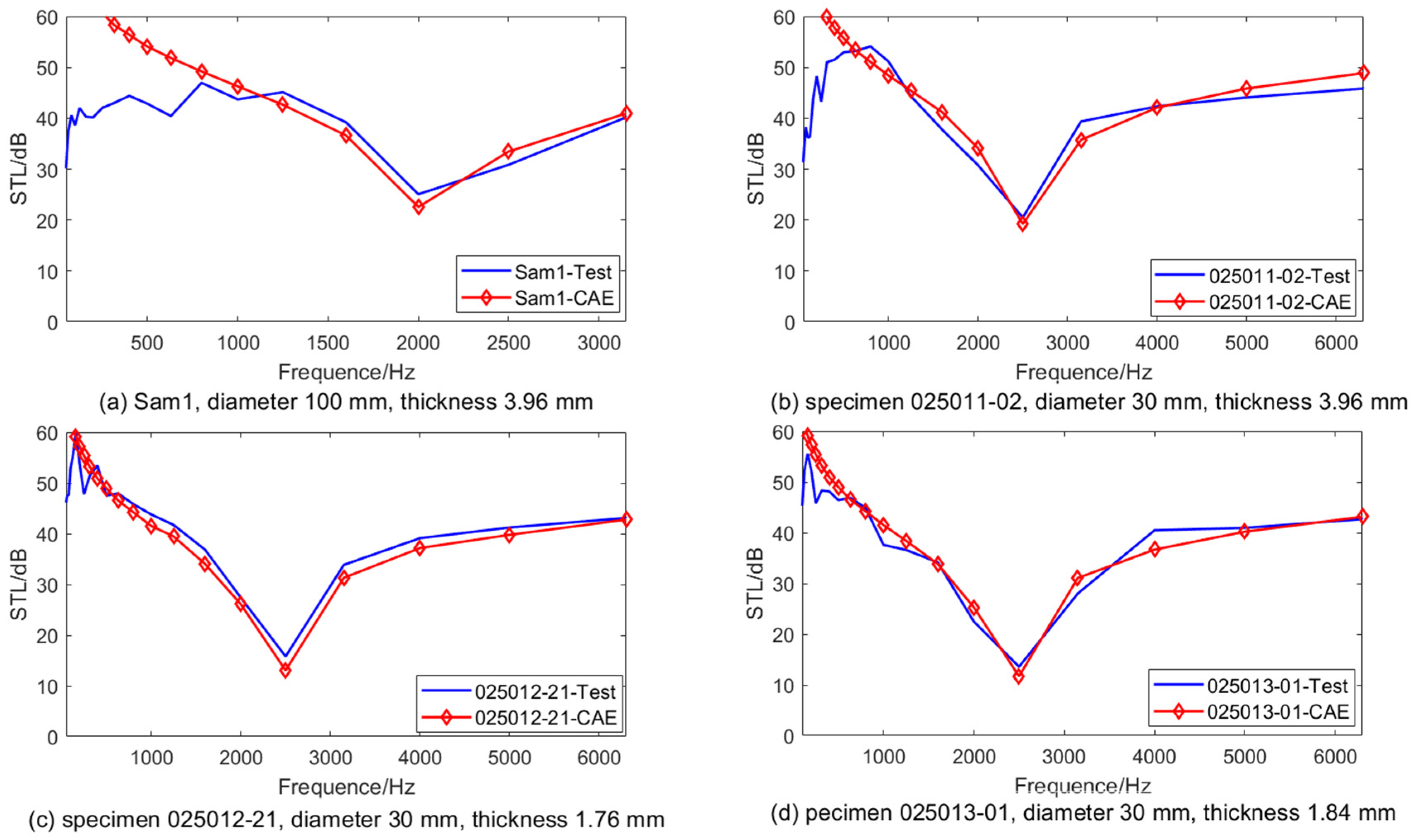
A comparison of the finite element simulation results with the impedance tube test results is shown in Figure 7. In the figures, “CAE” (computer-aided engineering) refers to the simulated (finite-element) results and “Test” to the measured results. Overall, the simulation curves for the mid-to-high-frequency range show good agreement with the test curves, with consistent trends and peak/valley positions; however, there is some deviation in the low-frequency range, although the general trend remains consistent.
In the frequency range below 1000 Hz, an analysis of the discrepancies between simulation and test results reveals significant insights into the sound insulation performance of composite panels. The findings indicate that thicker composite panels show higher stiffness, which directly impacts the test results through the rigidity of the specimen’s sealing mechanism. This is exemplified by specimens Sam1 and 025011-02, where the low-frequency test and simulation results show significant deviations. This discrepancy arises because the stiffness of the specimen closely matches that of the sealing structure, leading to a significant contribution from both components and amplifying the deviation. This stiffness coupling mechanism can be understood as follows: for thicker specimens such as Sam1 and 025011-02 (3.96 mm), the bending stiffness of the specimen is of the same order of magnitude as the sealing structure stiffness, resulting in strong coupling effects.
For the effective frequency band above 1000 Hz, a quantitative error analysis was carried out and summarized in Table 4. The results indicate that the mean absolute errors (MAE) for all four specimens are below 3 dB, with 025012-21 showing an MAE of 1.94 dB and 025011-02 demonstrating an MAE of 2.28 dB. The root mean square errors (RMSEs) range from 2.09 dB to 2.56 dB. The maximum single-point errors across all specimens range from 2.6 dB to 3.9 dB. Note that the maximum errors of 3.6 dB and 3.9 dB slightly exceed the ±3 dB criterion at individual frequency points, while the majority of frequency points satisfy the engineering precision requirement. Overall, the data presented in Table 4 validate the accuracy of the simulation model for predicting sound insulation performance above 1000 Hz.
Across all impedance tube specimens, the simulation tends to slightly underestimate sound insulation in the 2000–3000 Hz range. Still, the good agreement between simulation and experimental results confirms the reliability of the finite element model in this frequency band, supporting its use for metamaterial design optimization.

5. Design of Membrane-Type Metamaterials for Targeted Sound Insulation

5.1. Design Objectives and Constraints

To enhance the sound insulation performance of composite material components, thin-film metamaterial compositing technology has been applied to process the composite material specimens. The optimization objective is clearly defined as: within the 2000–3000 Hz frequency band, improve the sound insulation performance and ensure that the structural valley sound insulation level increases by at least 3 dB [30]; simultaneously, the constraint condition stipulates that the additional weight of the metamaterial must not exceed 5% of the original composite material specimen’s weight. This frequency band corresponds to the primary energy range of turbulent boundary layer noise and represents a critical frequency range for mid-to-low frequency noise control in the cabin, thus holding significant practical application value.
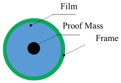
The optimization design variables include: film thickness (0.05–0.2 mm), mass density of the counterweight (800–9000 kg/m3), and maximum counterweight mass of 2.29 g (5% of the 45.80 g panel). A schematic diagram of the film structure is shown in Figure 8.

5.2. Membrane-Type Material Parameter Calibration

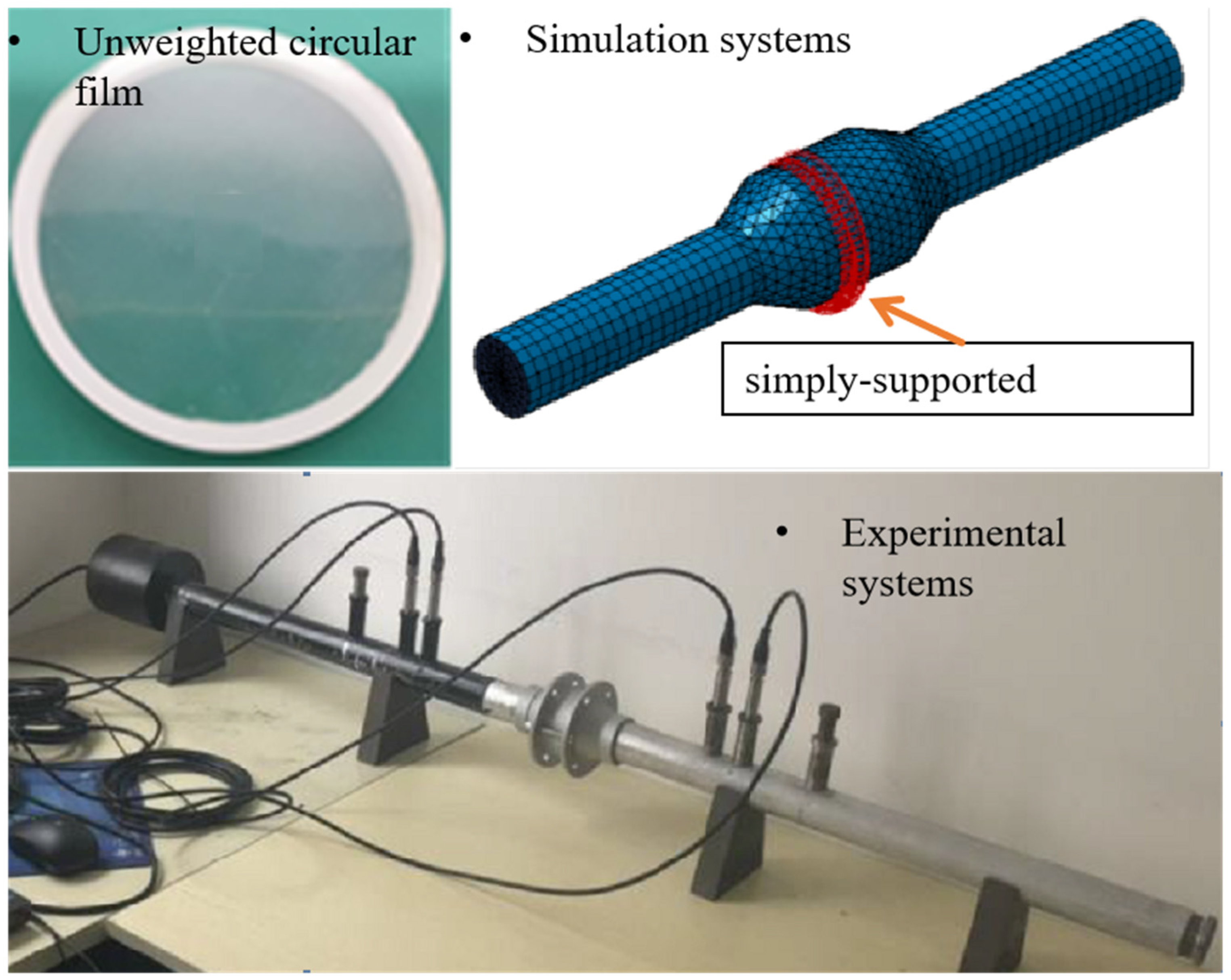
Due to the non-uniform thickness of the film, discrepancies exist between nominal parameters and actual equivalent parameters. Therefore, an acoustic parameter calibration was first carried out for the Polyethylene Terephthalate (PET) substrate film using a combined “experimentation and inversion” approach to determine the equivalent Young’s modulus. The procedure involved fabricating unweighted circular film specimens and testing their sound insulation curves using an impedance tube. Simultaneously, a finite element model was established, with Young’s modulus as the variable in iterative computations. When the simulation curve achieved optimal alignment with the test curve, the corresponding parameters were identified as the calibrated values. The experimental and simulation systems are shown in Figure 9. The calibration results are shown in Table 5.

5.3. Membrane-Type Metamaterial Design

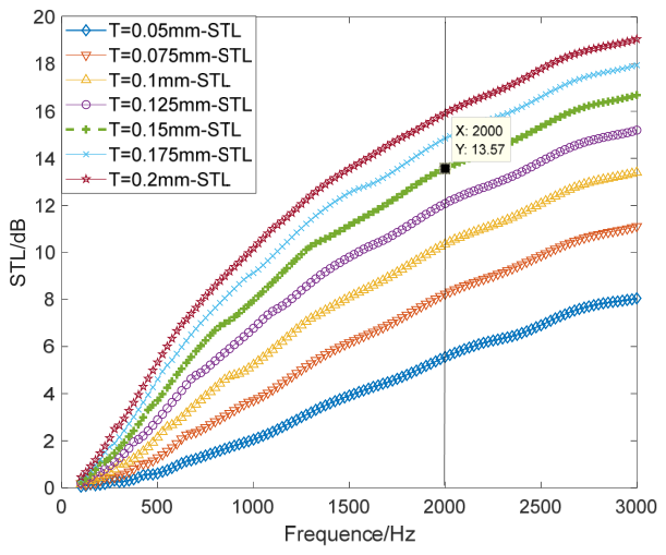
Sound insulation simulations were carried out for film thicknesses ranging from 0.05 to 0.2 mm, and the results are presented in Figure 10. As the film thickness increases from 0.05 to 0.2 mm, both the mass per unit area and structural damping increase simultaneously, leading to a continuous improvement in sound insulation performance at 2000 Hz. Considering that 0.15 mm is the standard production scale for domestically produced PET films, with mature processes such as die-cutting and bonding, and achieving a sound insulation efficiency of 13.57 dB at 2000 Hz, the base film design thickness was determined to be 0.15 mm [31].
The equivalent stiffness range at the center of the finite element model was extracted as 14,200–15,800 N/m. Based on the simplified formula for localized resonance f a n t u = 1 2 π k m , the theoretical mass range was calculated to be between 0.09 and 0.1 g. Ultimately, the thin-film metamaterial design was finalized as follows: a 0.15 mm PET film with a single central mass block weighing 0.1 g, and a frame weighing 0.1 g.

5.4. Experimental Validation

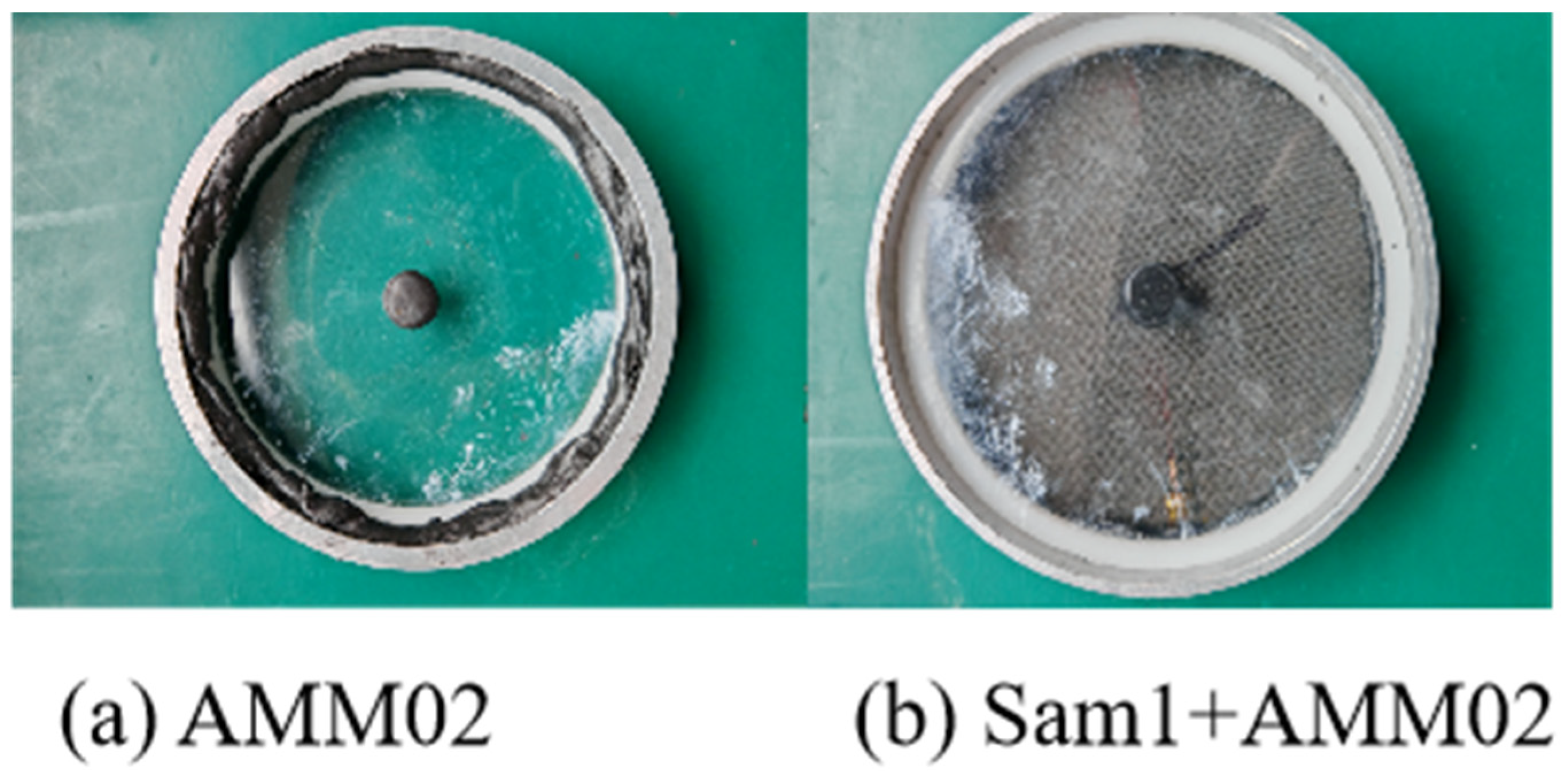
According to the optimized parameters, a film metamaterial specimen (designated as AMM02) was prepared. The substrate used was a 150 μm PET film, which was tensioned and fixed using a ring fixture. The total mass of the final specimen was approximately 1.05 g, consisting of a 0.15 mm thick PET film weighing 0.85 g, a single central mass block weighing 0.1 g, and a frame weighing 0.1 g. The AMM02 film metamaterial was then combined with the Sam1 composite material specimen to form a composite sound insulation structure consisting of “composite material + film metamaterial,” [32] as shown in Figure 11.
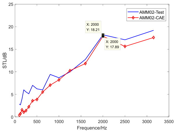
The simulation and analysis results of the sound insulation characteristics of the AMM02 specimen are shown in Figure 12. The simulation and experimental results validate the effectiveness of the parameters, showing a clear anti-resonance peak at 2000 Hz, with an increase of 4.64 dB compared to the pure membrane structure (13.57 dB).
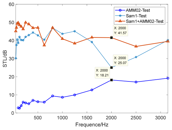
The quantitative comparison before and after metamaterial integration is presented in Figure 13 and Table 6. The test results show that with only a 2.29% weight increase, the sound insulation performance improves by 16.5 dB at the 2000 Hz valley. This gain is well above what the mass law predicts for the same added mass, confirming that the anti-resonance mechanism rather than mass loading is responsible.
To further understand the enhancement mechanism, three configurations were compared: the bare Sam1 panel, AMM02 alone, and the Sam1–AMM02 composite structure. The bare Sam1 panel shows an STL valley of 25.07 dB at 2000 Hz, typical of the coincidence effect in thin composite panels. AMM02 alone produces an anti-resonance peak at 2000 Hz, with an experimental STL of approximately 18.21 dB (simulation: 17.89 dB), a 4.64 dB gain over the baseline film. When AMM02 is coupled to Sam1 with a 3 mm air gap, the composite structure reaches 41.57 dB at 2000 Hz—a 16.5 dB improvement over the bare panel. This 16.5 dB value is a point measurement at the 2000 Hz valley under normal incidence; it is not a broadband average. The >3 dB bandwidth spans roughly 1800–2200 Hz, and the band-averaged gain over 2000–3000 Hz is about 8–10 dB.

6. Discussion

The results show that membrane-type acoustic metamaterials can provide targeted sound insulation enhancement with minimal added weight. Attaching a 150 μm PET membrane (0.85 g) with a 0.1 g central proof mass and a 0.1 g supporting frame (total assembly mass 1.05 g) to the Sam1 composite panel yields a 16.5 dB STL improvement at 2000 Hz with a 2.29% weight increase. This gain is well above what the mass law would predict for the same added mass, confirming that the anti-resonance mechanism rather than mass loading is responsible for the improvement. The result is encouraging for weight-critical applications, though it should be read as a unit-cell, normal-incidence result rather than a diffuse-field panel-level performance.
Experimental validation confirms that the designed membrane metamaterial effectively introduces localized resonance at the target frequency, significantly modifying the dynamic response of the composite structure. This mechanism is consistent with theoretical predictions derived from the local resonance principle, wherein the mass and stiffness parameters of the membrane collectively determine the anti-resonant frequency. The calibration procedure for PET film material parameters further supports the accuracy of the finite element model, to ensure reliable simulation predictions across the frequency range of interest.
The practical significance of this research is particularly relevant to aircraft cabin noise control, where mid-frequency noise induced by turbulent boundary layers remains a persistent challenge. By directly targeting the critical frequency band associated with such noise sources, the proposed membrane metamaterial offers a viable lightweight solution for noise reduction in transportation systems including aircraft, high-speed trains, and automotive vehicles [33].
This study also contributes to the broader field of acoustic metamaterials by showing that engineered membrane thickness and concentrated mass placement can be exploited to achieve targeted acoustic performance. The adopted methodology, combining experimental characterization with inverse parameter calibration, provides a systematic framework for membrane metamaterial design. This approach ensures that nominal material properties are accurately mapped to actual acoustic behavior, improving the predictive reliability of numerical simulations [34].
Future research will extend the current design toward broader frequency coverage through multi-mass configurations and graded thickness distributions. In addition, the synergy between membrane metamaterials and other noise control techniques, such as damping layers and multi-layered structures, needs further study. The compatibility of these lightweight solutions with existing structural systems, coupled with their minimal weight penalty, renders them highly attractive for aerospace, automotive, and other weight-sensitive industrial applications [35].
In summary, this study shows that innovative membrane metamaterial designs can effectively address the mid-frequency sound insulation deficiency of lightweight composite structures. With minimal weight penalty, significant STL enhancement is achieved at the target frequency, offering a practical pathway toward efficient lightweight noise control solutions for engineering applications.

7. Conclusions

This study addresses the mid-frequency sound insulation deficiency of aeronautical CFRP composite panels through the design and experimental validation of a membrane-type acoustic metamaterial. The main conclusions are as follows: (1) A structure–acoustic coupled finite element model with equivalent boundary stiffness was established and validated against impedance tube tests. The mean absolute error above 1000 Hz is within 3 dB, with a maximum single-point error of 3.9 dB. The CFRP specimen shows a distinct sound insulation valley at 2000 Hz. (2) A forward-design procedure for membrane metamaterials under a 5% weight constraint is proposed. Within the 50–200 μm thickness range, sound insulation increases monotonically with thickness without resonance frequency shift. A 150 μm PET film with a 0.1 g central proof mass and a 0.1 g frame (total 1.05 g) was selected as the final design. (3) Both AMM02-only and composite structure tests confirm the design. With a 2.29% weight increase, a 16.5 dB STL enhancement at 2000 Hz was achieved under normal incidence at the unit-cell level, exceeding the 3 dB design target. Comparison of the bare panel, AMM02-only, and composite structure results indicates a synergistic interaction between the metamaterial and the panel. (4) A complete design flow of ‘material calibration–membrane selection–target frequency tuning–experimental validation’ is established, providing an engineering reference for mid-frequency noise reduction in aircraft cabins.
Note that this work presents a unit-cell-level proof-of-concept study. Large-scale panel tests and environmental durability evaluations will be conducted in future engineering development.
In addition, the current study focuses on single-frequency optimization at 2000 Hz, while actual aircraft cabin noise covers a broader spectrum. Future work will explore multi-frequency and broadband sound insulation requirements through two approaches: (1) multi-mass configurations, where proof masses of different weights are distributed across the membrane to create multiple anti-resonance peaks at targeted frequencies; and (2) graded thickness distributions, where the membrane thickness varies spatially to achieve a continuous broadband insulation effect.

Author Contributions

C.H. is responsible for theoretical modeling, simulation analysis, experimental research, and data analysis; Y.N. participated in the discussion of the experimental plan; J.G. participated in the discussion of the results of the simulation analysis. All authors have read and agreed to the published version of the manuscript.

Funding

This research was funded by the Ministry of Industry and Information Technology, Project Name: “Noise Pilot”.

Data Availability Statement

The raw experimental datasets, finite element model parameters, and calibration records generated during this research are available from the corresponding author upon reasonable request for academic purposes. Due to internal research management and confidentiality requirements, the complete raw datasets cannot be publicly deposited in a repository. However, all essential model parameters, material properties, boundary conditions, and calibration procedures have been documented in detail in Section 3 of this revised manuscript to ensure reproducibility. Researchers interested in additional details may contact the corresponding author for reasonable academic communication.

Conflicts of Interest

The authors declare no conflicts of interest.

Abbreviations

The following abbreviations are used in this manuscript:
ICAOThe International Civil Aviation Organization
CFRPCarbon fiber-reinforced polymer
STLSound Transmission Loss
DOFDegrees Of Freedom
MAEMean Absolute Error
RMSERoot Mean Square Error
CAEComputer-Aided Engineering
PETPolyethylene Terephthalate

References

  1. Liu, Z.; Rumpler, R.; Feng, L. Broadband locally resonant metamaterial sandwich plate for improved noise insulation in the coincidence region. Compos. Struct. 2018, 200, 165–172. [Google Scholar] [CrossRef] [Scilit]
  2. Yang, Z.; Dai, H.M.; Chan, N.H.; Ma, G.C.; Sheng, P. Acoustic metamaterial panels for sound attenuation in the 50–1000 Hz regime. Appl. Phys. Lett. 2010, 96, 041906. [Google Scholar] [CrossRef] [Scilit]
  3. Yang, Z.; Mei, J.; Yang, M.; Chan, N.H.; Sheng, P. Membrane-type acoustic metamaterial with negative dynamic mass. Phys. Rev. Lett. 2008, 101, 204301. [Google Scholar] [CrossRef] [Scilit] [PubMed]
  4. Naify, C.J.; Chang, C.M.; McKnight, G.; Nutt, S.R. Transmission loss and dynamic response of membrane-type locally resonant acoustic metamaterials. J. Appl. Phys. 2010, 108, 114905. [Google Scholar] [CrossRef] [Scilit]
  5. Ma, F.; Wang, C.; Liu, C.; Wu, J.H. Structural designs, principles, and applications of thin-walled membrane and plate-type acoustic/elastic metamaterials. J. Appl. Phys. 2021, 129, 231103. [Google Scholar] [CrossRef] [Scilit]
  6. Zhang, Y.G. Thin-Film Type Acoustic Metamaterial Sound Insulation Characteristics Research. Master’s Thesis, National University of Defense Technology, Changsha, China, 2010. [Google Scholar]
  7. Wu., J.; Ma, F.; Zhang, S.; Shen, L. Application of acoustic metamaterials in low-frequency vibration and noise reduction. J. Mech. Eng. 2016, 52, 68. [Google Scholar] [CrossRef] [Scilit]
  8. Zhou, G.; Wu, J.H.; Lu, K.; Tian, X.; Huang, W.; Zhu, K. Broadband low-frequency membrane-type acoustic metamaterials with multi-state anti-resonances. Appl. Acoust. 2019, 159, 107078. [Google Scholar] [CrossRef] [Scilit]
  9. Li, J.; Shi, Y.; Jiang, R.; Zhang, Z.; Huang, Q. Acoustic Insulation Mechanism of Membrane-Type Acoustic Metamaterials Loaded with Arbitrarily Shaped Mass Blocks of Variable Surface Density. Materials 2022, 15, 1556. [Google Scholar] [CrossRef] [Scilit] [PubMed]
  10. Wang, S.C. Lightweight Design of Acoustic Metamaterials for Aircraft Cabin Noise Reduction. Ph.D. Thesis, Nanjing University of Aeronautics and Astronautics, Nanjing, China, 2022. [Google Scholar]
  11. Janssen, S.; Van Belle, L.; Rocha de Melo Filho, N.G.; Desmet, W.; Claeys, C.; Deckers, E. Improving the noise insulation performance of vibro-acoustic metamaterial panels through multi-resonant design. Appl. Acoust. 2023, 213, 109622. [Google Scholar] [CrossRef] [Scilit]
  12. Palma, G.; Mao, H.; Burghignoli, L.; Göransson, P.; Iemma, U. Acoustic Metamaterials in Aeronautics. Appl. Sci. 2018, 8, 971. [Google Scholar] [CrossRef] [Scilit]
  13. Song, Y.; Chen, S.; Zuo, K.; Huang, B.; Wen, J. Low frequency acoustic properties of a metamaterial-based aircraft trim panel. In Proceedings of the 25th AIAA/CEAS Aeroacoustics Conference, Delft, The Netherlands, 20–23 May 2019. [Google Scholar]
  14. Pires, F.A.; Wandel,, M.; Thomas, C.; Deckers, E.; Desmet, W.; Claeys, C. Improving the Sound Transmission Loss of an Aircraft Ceiling Panel by Locally Resonant Metamaterials. In Proceedings of the 12th International Styrian Noise, Vibration & Harshness Congress: The European Automotive Noise Conference, Graz, Austria, 22 June–22 October 2022. [Google Scholar] [CrossRef] [Scilit]
  15. Zheng, Y.S.; Yuan, H.B.; Qu, Y.G.; Meng, G. Advances in thin-walled metastructures for vibration and noise control and their applications in aerospace engineering. Adv. Mech. 2026, 56, 51–122. [Google Scholar] [CrossRef]
  16. Zhang, Y.; Zhang, J.; Li, Y.; Yao, D.; Zhao, Y.; Ai, Y.; Pan, W.; Li, J. Research Progress on Thin-Walled Sound Insulation Metamaterial Structures. Acoustics 2024, 6, 298–330. [Google Scholar] [CrossRef] [Scilit]
  17. Lu, Q.; Li, X.; Zhang, X.; Lu, M.; Chen, Y. Perspective: Acoustic Metamaterials in Future Engineering. Engineering 2022, 17, 156–170. [Google Scholar] [CrossRef] [Scilit]
  18. Droz, C.; Robin, O.; Ichchou, M.; Atalla, N. Improving sound transmission loss at ring frequency of a curved panel using tunable 3D-printed small-scale resonators. J. Acoust. Soc. Am. 2019, 145, EL72–EL78. [Google Scholar] [CrossRef] [Scilit] [PubMed]
  19. Wang, X.; Chen, Y. Synergetic coupling large-scale plate-type acoustic metamaterial panel for broadband sound insulation. J. Sound Vib. 2019, 459, 114867. [Google Scholar] [CrossRef] [Scilit]
  20. Marinova, P.; Lippert, S.; von Estorff, O. On the numerical investigation of sound transmission through double-walled structures with membrane-type acoustic metamaterials. J. Acoust. Soc. Am. 2017, 142, 2400–2406. [Google Scholar] [CrossRef] [Scilit]
  21. Mo, J.; Peng, Z.; Wang, X. Achieving Enhanced Sound Insulation through Micromembranes-Type Acoustic Metamaterials. Appl. Sci. 2022, 12, 1950. [Google Scholar] [CrossRef] [Scilit]
  22. Zhang, X.A. Study on Sound Insulation Characteristics of Local Resonance Membrane-Type Acoustic Metamaterials. Ph.D. Thesis, Xi’an Jiaotong University, Xi’an, China, 2019. [Google Scholar]
  23. Langfeldt, F.; Gleine, W.; von Estorff, O. Analytical model for low-frequency transmission loss calculation of membranes loaded with arbitrarily shaped masses. J. Sound Vib. 2015, 349, 315–329. [Google Scholar] [CrossRef] [Scilit]
  24. Langfeldt, F.; Gleine, W. Membrane- and plate-type acoustic metamaterials with elastic unit cell edges. J. Sound Vib. 2019, 453, 65–86. [Google Scholar] [CrossRef] [Scilit]
  25. Roca, D.; Hussein, M.I. Broadband and intense sound transmission loss by a coupled-resonance acoustic metamaterial. Phys. Rev. Appl. 2021, 16, 054018. [Google Scholar] [CrossRef] [Scilit]
  26. Shen, C.; Xin, F.X.; Lu, T.J. Sound transmission across composite laminate sandwiches: Influence of orthogonal stiffeners and laminate layup. Compos. Struct. 2016, 143, 310–316. [Google Scholar] [CrossRef] [Scilit]
  27. Wang, Y.; Ma, L. Sound insulation performance of membrane-type metamaterials combined with pyramidal truss core sandwich structure. Compos. Struct. 2021, 260, 113257. [Google Scholar] [CrossRef] [Scilit]
  28. GB/Z 27764-2011; Acoustics—Determination of Sound Transmission Loss in Impedance Tubes—Transfer Matrix Method. Standards Press of China: Beijing, China, 2011.
  29. Dong, N.J.; Peng, T.; Yan, Q. Analysis of sound insulation performance of composite aircraft panels in low temperature environments. Tech. Acoust. 2022, 41, 887–893. [Google Scholar] [CrossRef]
  30. Giannini, D.; Schevenels, M.; Reynders, E.P.B. Locally resonant metamaterials with multi-modal resonators for maximized broadband sound insulation. J. Sound Vib. 2025, 595, 118691. [Google Scholar] [CrossRef] [Scilit]
  31. Nguyen, H.; Wu, Q.; Chen, J.; Yu, Y.; Chen, H.; Tracy, S.; Huang, G. A broadband acoustic panel based on double-layer membrane-type metamaterials. Appl. Phys. Lett. 2021, 118, 184101. [Google Scholar] [CrossRef] [Scilit]
  32. Lin, Q.; Lin, Q.; Wang, Y.; Di, G. Sound insulation performance of sandwich structure compounded with a resonant acoustic metamaterial. Compos. Struct. 2021, 273, 114312. [Google Scholar] [CrossRef] [Scilit]
  33. Sal-Anglada, G.; Yago, D.; Cante, J.; Oliver, J.; Pàmies, T.; Roca, D. Transverse coupled resonances for ultrathin lightweight acoustic metamaterials. Thin-Walled Struct. 2025, 213, 113219. [Google Scholar] [CrossRef] [Scilit]
  34. Liu, D.; Hao, L.; Zhu, W.; Yang, X.; Yan, X.; Guan, C.; Xie, Y.; Pang, S.; Chen, Z. Recent Progress in Resonant Acoustic Metasurfaces. Materials 2023, 16, 7044. [Google Scholar] [CrossRef] [Scilit] [PubMed]
  35. Kumar, S.; Lee, H.P. Recent Advances in Acoustic Metamaterials for Simultaneous Sound Attenuation and Air Ventilation Performances. Crystals 2020, 10, 686. [Google Scholar] [CrossRef] [Scilit]
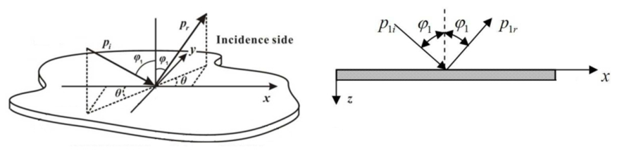
Figure 1. Sound Transmission Through a Single-Layer Panel.
Machines 14 01042 g001
Figure 2. Composite material specimens suitable for impedance tube testing.
Machines 14 01042 g002
Figure 3. Composite material specimen sound insulation analysis finite element model.
Machines 14 01042 g003
Figure 4. Test equipment: CIT30/100 impedance tube.
Machines 14 01042 g004
Figure 5. Schematic diagram of the impedance tube test system.
Machines 14 01042 g005
Figure 6. The sound insulation simulation curves for the four specimens.
Machines 14 01042 g006
Figure 7. Comparison of Analysis and Test Results on the Sound Insulation Performance of Material Samples.
Machines 14 01042 g007
Figure 8. Schematic diagram of membrane assembly.
Machines 14 01042 g008
Figure 9. The experimental and simulation systems.
Machines 14 01042 g009
Figure 10. Sound Insulation Performance for Films with Different Thicknesses.
Machines 14 01042 g010
Figure 11. Composite Soundproofing Structure.
Machines 14 01042 g011
Figure 12. Comparison of simulated and experimental sound insulation of the AMM02 specimen.
Machines 14 01042 g012
Figure 13. STL comparison before and after metamaterial integration.
Machines 14 01042 g013
Table 1. Basic parameters of composite material component-level specimens.
Specimen NumberDiameter (mm)Weight
(g)
Material System Layup MethodThickness (mm)
Sam110045.8AC531/CF8611[45/45/0/0/45/45/0/0/45]s3.96
025011-02304.43AC531/CF8611[45/45/0/0/45/45/0/0/45]s3.96
025012-21301.84AC531/CF8611[45/0/45/0/0/45/0/45]1.76
025013-01302.105228A/CF3031[45/0/45/0/0/45/0/45]1.84
Table 2. Performance Parameters of Composite Material.
MaterialSymbolElastic Constant (GPa)Density
(kg/m3)
Poisson’s RatioSingle-Ply Thickness
(mm)
AC531/CF8611E1115515800.0460.23
E229.80
G124.96
5228A/CF3031E116515800.30.21
E2262.3
G126.5
Table 3. Parameters of the equivalent rubber layer model.
Ring Diameter
mm
Young’s Modulus
(MPa)
Density
(kg/m3)
Poisson’s Ratio
10075,00015800.3
301115800.46
Table 4. Error Statistics of Simulation and Test Sound Insulation (Above 1000 Hz).
Specimen NumberMaximum Single-Point Error (dB)Mean Absolute Error
(dB)
Root Mean Square Error (dB)Precision Requirement
(dB)
Compliance
Sam12.62.232.34<3
025011-023.62.282.56<3Mostly
025012-212.81.942.09<3
025013-013.92.092.49<3Mostly
Table 5. Calibrated PET Film Material Parameters.
Young’s Modulus
MPa
Poisson’s RatioDensity
kg/m3
Thickness
mm
Loss Factor
38000.3216000.150.12
Table 6. Comparison of Weight and Sound Insulation Performance Before and After Optimization.
SpecimenTotal Weight
g
Frequency
Hz
STL
dB
Weight Increase STL Improvement
dB
Sam1 45.80 2000 25.07 —— ——
AMM02 1.05 2000 18.21 —— ——
Sam1 + AMM02 46.85 2000 41.57 2.29% 16.5
Disclaimer/Publisher’s Note: The statements, opinions and data contained in all publications are solely those of the individual author(s) and contributor(s) and not of MDPI and/or the editor(s). MDPI and/or the editor(s) disclaim responsibility for any injury to people or property resulting from any ideas, methods, instructions or products referred to in the content.