Article

Error Analysis and Drive Optimization of a Minimally Invasive Surgical Robot
1
School of Mechanical and Electrical Engineering, Shenyang Aerospace University, No. 37, Daoyi South Street, Shenbei New District, Shenyang 110000, China
2
School of Mechanical and Electrical Engineering, PLA Army Services University, Shenyang 110000, China
*
Author to whom correspondence should be addressed.
Machines 2026, 14(6), 584; https://doi.org/10.3390/machines14060584
Submission received: 17 April 2026 / Revised: 19 May 2026 / Accepted: 22 May 2026 / Published: 25 May 2026
(This article belongs to the Special Issue Design and Control of Surgical Robots)

Abstract

Cable-driven minimally invasive surgical robots suffer from significant motion inaccuracies due to nonlinear transmission effects such as friction, elasticity, and hysteresis. These factors lead to strong nonlinear and direction-dependent behaviors, making accurate modeling and compensation challenging. To address this issue, this study investigates the error characteristics of a cable-driven surgical robot prototype based on its structural features. A kinematic model is first established, and geometric errors are corrected through Denavit–Hartenberg (DH) parameter identification using a least-squares method. To further characterize nonlinear effects, the LuGre friction model and equivalent stiffness theory are introduced to analyze friction and cable deformation behaviors. Since physics-based models alone cannot accurately capture the coupled nonlinear errors, a radial basis function (RBF) neural network is employed to approximate the residual errors. To enable real-time implementation, the predicted errors are further simplified using equivalent polynomial functions for efficient compensation. Experimental results demonstrate that the proposed method significantly improves the motion accuracy of the cable-driven system, effectively reducing both tracking error and hysteresis effects. By integrating mechanism-based modeling with data-driven compensation, this approach provides a practical and effective solution for precision enhancement in cable-driven surgical robotic systems.

1. Introduction

With the rapid advancement of medical engineering and intelligent instrumentation, minimally invasive surgical (MIS) robots have become increasingly integral to modern clinical practice [1]. Compared with conventional open surgery, MIS robotic procedures are performed through small incisions or natural orifices, significantly reducing tissue trauma, shortening postoperative recovery time, and lowering the incidence of complications [2]. Against this background, surgical robots serve as a critical interface between the surgeon’s intent and precise execution. Due to their superior stability, repeatability, and high-precision motion control capabilities, these systems have been widely adopted in high-demand clinical domains such as cardiovascular surgery, neurosurgery, and urology [3]. Representative platforms, such as the da Vinci Surgical System, employ master–slave control architectures to enable motion scaling and tremor suppression, thereby enhancing the safety and reliability of complex surgical procedures [4].
From a structural perspective, the stringent requirements of MIS—including miniaturized instrument profiles, remote actuation, and enhanced workspace accessibility—have led to the widespread adoption of cable-driven mechanisms in robotic end-effector systems [5]. By transmitting actuation forces through flexible pathways from remotely located actuators, cable-driven designs offer distinct advantages such as compact structure, low distal inertia, and high configurational flexibility. However, in stark contrast to rigid transmission systems, cable-driven mechanisms inherently suffer from elastic deformation, nonlinear friction, and path-dependent behavior, resulting in a highly complex and nonlinear mapping between actuator inputs and end-effector outputs [6]. This challenge is further exacerbated in scenarios involving multiple routing paths and curved conduits, where cable tension progressively attenuates along the transmission path. During motion reversals, pronounced hysteresis effects emerge, leading to delayed system responses and degraded positioning accuracy [7].
Moreover, the inherently low equivalent stiffness of cable-driven systems introduces additional sources of uncertainty. Their transmission characteristics are not only governed by material elasticity but are also strongly influenced by routing geometry, contact friction conditions, and preload distribution [8]. Under external disturbances or varying loads, the redistribution of internal cable tension can induce additional deformation, resulting in unintended deviations in the end-effector pose. Such coupled effects of low stiffness and nonlinear dynamics are particularly detrimental in high-precision surgical contexts, where even minute positioning errors may propagate into clinically significant risks [9].
Extensive efforts have been devoted to improving the accuracy of cable-driven robotic systems. Conventional approaches primarily rely on kinematic calibration and parameter identification, wherein geometric models are established and Denavit–Hartenberg parameters are refined to mitigate systematic errors arising from assembly imperfections and structural deviations. However, these methods are fundamentally limited, as they fail to capture the intrinsic nonlinearities associated with cable-driven actuation, particularly friction-induced hysteresis and elastic effects. To address this limitation, physics-based friction models, such as the LuGre dynamic friction model, have been introduced to describe hysteresis and presliding displacement through internal state variables, thereby enhancing the fidelity of system modeling [10]. Nevertheless, despite their strong physical interpretability, such models suffer from significant practical challenges, including complex parameter identification and limited robustness under varying operating conditions.
In recent years, the emergence of data-driven methodologies has provided new avenues for modeling and compensating complex nonlinear systems [11]. Neural network-based approaches, particularly those employing radial basis function (RBF) networks, have been widely applied to learn the nonlinear mapping between actuator inputs and end-effector responses using experimentally collected data. These methods exhibit strong approximation capability and adaptability, enabling effective compensation of error components that are difficult to model analytically. However, purely data-driven approaches are not without drawbacks: they often lack physical interpretability and may suffer from limited generalization performance, especially when operating beyond the range of training data [12].
Therefore, a critical challenge remains: how to effectively integrate data-driven techniques with physics-based models to compensate complex nonlinear errors while preserving system stability and interpretability. To address this issue, this paper proposes a hybrid accuracy enhancement framework that combines model-based and data-driven strategies. First, geometric errors are addressed by establishing a kinematic model of the robot, followed by the identification and compensation of DH parameters using the least-squares method [13]. Building upon this foundation, a feedforward compensation model based on an RBF neural network is developed to capture the nonlinear and hysteretic characteristics of cable-driven degrees of freedom. By learning the residual mapping between desired commands and actual responses, the proposed method enables the rapid correction of end-effector deviations. Ultimately, a cascaded framework integrating DH parameter calibration and RBF-based residual compensation is constructed, which significantly reduces system errors while maintaining model stability. This approach provides a robust and effective solution for achieving high-precision positioning and stable control in minimally invasive surgical robots.
The main contributions of this paper can be summarized as follows:
(1) A coupled error modeling framework for cable-driven minimally invasive surgical robots is established by considering geometric errors, structural deflection, and nonlinear friction effects, providing a theoretical basis for the analysis of multi-source error propagation.
(2) A mechanism-based compensation method combining DH parameter identification and LuGre dynamic friction modeling is proposed to characterize geometric deviations and hysteresis-related nonlinear behaviors in cable-driven transmission systems.
(3) An RBF neural network-based feedforward compensation strategy is developed to learn and compensate for residual nonlinear errors that cannot be accurately described by analytical models, thereby improving the compensation accuracy of the system.
(4) A hybrid hierarchical compensation framework integrating model-based correction and data-driven residual learning is constructed and experimentally validated, demonstrating significant improvements in the positioning accuracy and dynamic response performance of the surgical robotic system.

2. Materials and Methods

2.1. Structure of the Minimally Invasive Surgical Robot

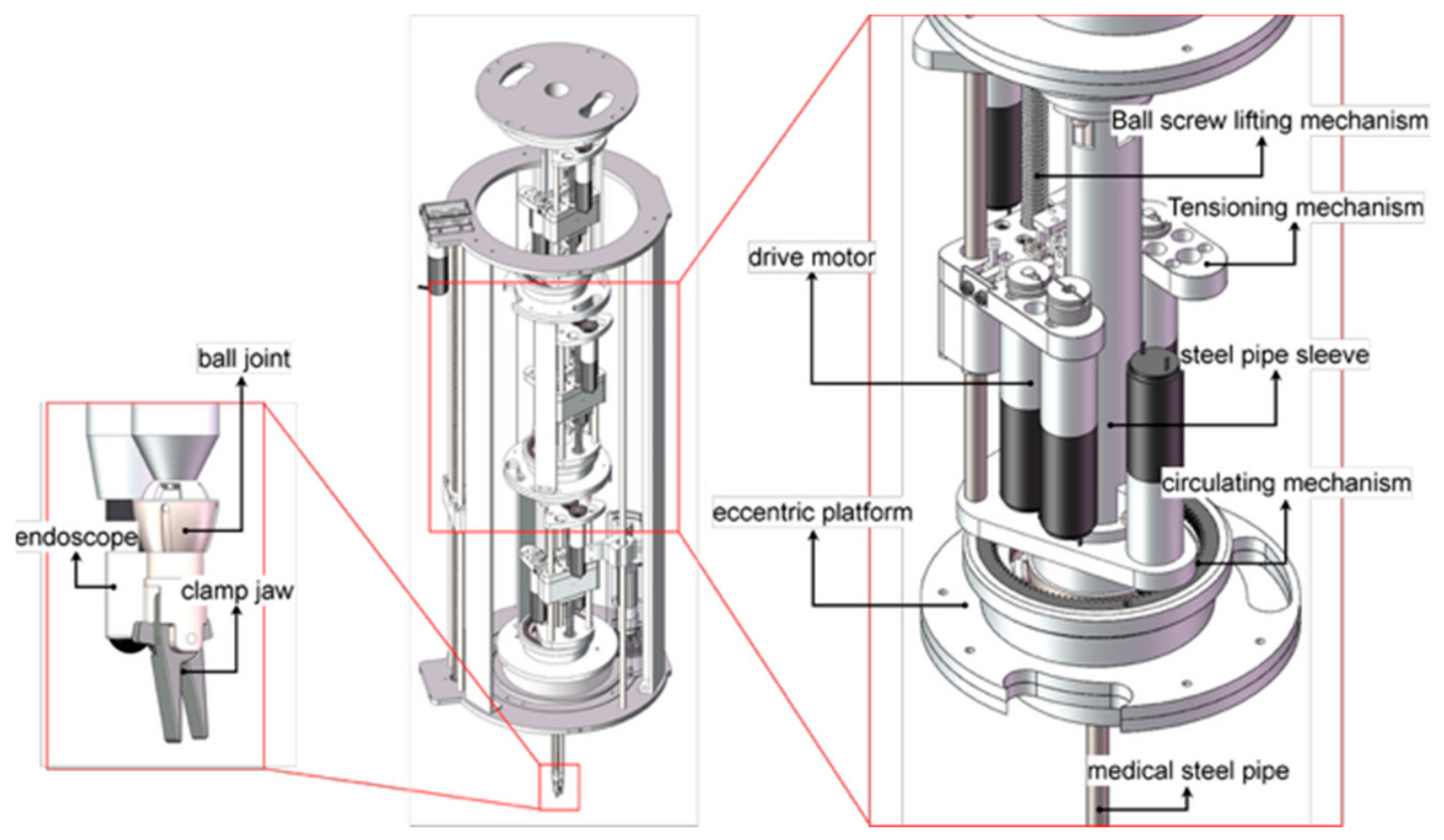
The overall configuration of the minimally invasive surgical robot is illustrated in Figure 1. The system investigated in this study consisted of three parallel modules arranged along the axial direction, exhibiting a highly modular and scalable architecture. Each module could be independently equipped with different types of end-effectors, such as endoscopes, grippers, or cutting instruments, to accommodate diverse clinical requirements.
Within the global structure, each module incorporated two degrees of freedom (DOFs) realized through rigid transmission mechanisms: a translational DOF and a rotational DOF. The translational motion was driven by an internal motor–lead screw mechanism, enabling precise axial extension and retraction of the module. The rotational motion was achieved by a motor-driven internal gear system mounted on the module body, allowing circumferential rotation. These rigid transmission chains provided high structural stiffness, stability, and predictable kinematic behavior.
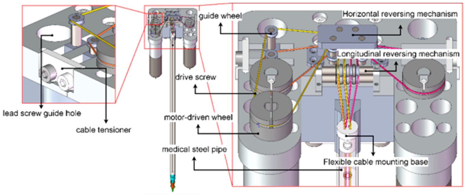
In addition to the rigid components, each module included three cable-driven DOFs, as shown in Figure 2, which were responsible for the fine manipulation of the end-effector (taking a gripper as an example). Internal motors actuated steel cables to control the pitch, yaw, and grasping motions of the gripper, thereby forming a complete manipulation unit. Cable-driven transmission offered advantages such as compact structure, low mass, and flexible remote actuation. However, it also introduced nonlinear effects including elastic deformation, friction, and hysteresis, which constituted the primary sources of positioning errors at the end-effector. Consequently, each module formed a five-DOF mechanism composed of a two-DOF rigid transmission chain and a three-DOF flexible (cable-driven) transmission chain. When combined in a parallel configuration, the three modules enabled coordinated execution of complex surgical tasks. This modular structure provided a clear framework for isolating error sources and establishing an experimental basis for end-effector accuracy compensation.

2.2. System Issues and Modeling

2.2.1. Error Sources in the Minimally Invasive Surgical Robot System

During practical surgical operations, the positioning and orientation accuracy of the robot end-effector are influenced by multiple factors [14]. For the cable-driven minimally invasive surgical robot investigated in this study, system errors were categorized into two types according to the transmission mechanism: rigid-component errors and flexible-component errors. The rigid components primarily included the lead screw-driven translational DOF and the gear-driven rotational DOF. These transmission mechanisms exhibited high stiffness and stability [15]. However, in practical operation, they were inevitably affected by assembly errors, inaccuracies in geometric parameter calibration, and manufacturing tolerances. For example, lead screw pitch errors and transmission backlash introduced deviations between the actual and theoretical translational displacements. Similarly, gear meshing clearance and tooth profile errors led to cumulative rotational inaccuracies. These geometric errors manifested as systematic deviations in both position and orientation in the end-effector coordinate frame and constituted a significant source of accuracy degradation.
The flexible components, corresponding to the pitch, yaw, and grasping DOFs, were actuated cable-driven mechanisms. While such systems provided advantages in compactness, low weight, and remote actuation, they also introduced elastic deformation, nonlinear friction, and path-dependent effects, which became dominant contributors to system inaccuracies.
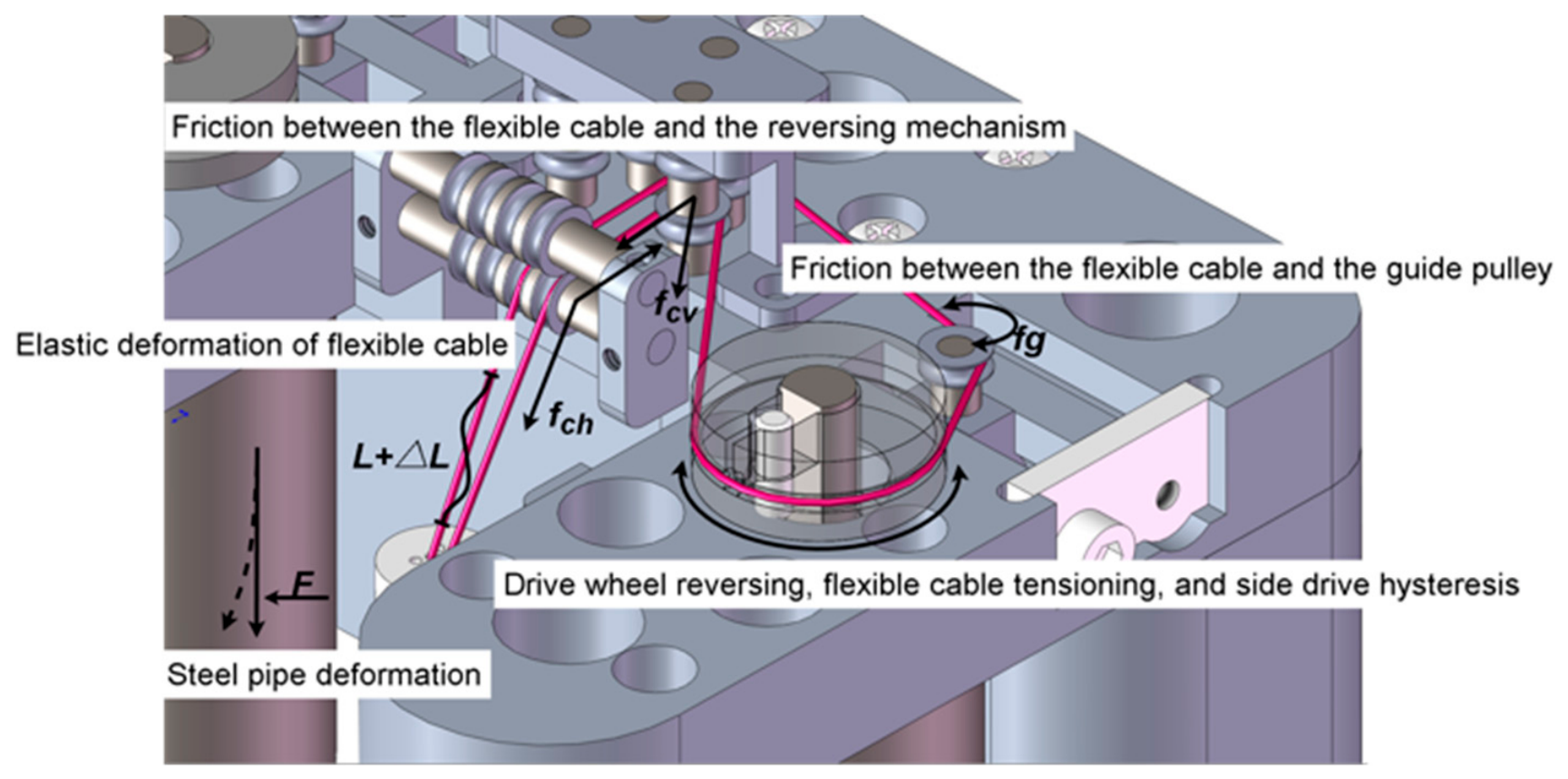
As illustrated in Figure 3, the error sources in the cable-driven system exhibited strong multi-factor coupling characteristics. On the one hand, elastic elongation occurred during cable tensioning and release, resulting in a nonlinear relationship between actuator input and joint output [16]. On the other hand, contact friction between the cables, pulleys, and guiding tubes introduced significant hysteresis effects, leading to direction-dependent output deviations during motion reversals [17].
Furthermore, force transmission in cable-driven systems was inherently non-ideal. Uneven tension distribution among multiple cables caused asymmetric motion at the end-effector [18]. In addition, slender structural components connected to the end-effector underwent slight deflection. This deformation altered both the cable force distribution and transmission path, thereby introducing additional pose errors. As a result, strong coupling existed among cable elasticity, frictional nonlinearity, and structural deflection, leading to highly nonlinear system behavior.
In summary, the positioning errors of the surgical robot end-effector originated from two principal sources. The first was geometric errors in the rigid transmission chain, including dimensional deviations and assembly inaccuracies. The second was non-geometric errors in the cable-driven system, primarily caused by cable elasticity, friction-induced hysteresis, and structural deflection. These errors not only produced static deviations in end-effector pose but also introduced hysteresis and response delays during dynamic motion, significantly affecting control accuracy and system stability. Therefore, ideal kinematic models alone were insufficient to accurately describe the actual system behavior. It was necessary to incorporate coupled cable–structure error models into the kinematic framework to more realistically capture the nonlinear transmission characteristics of the cable-driven system.

2.2.2. Kinematic Modeling of the Minimally Invasive Surgical Robot

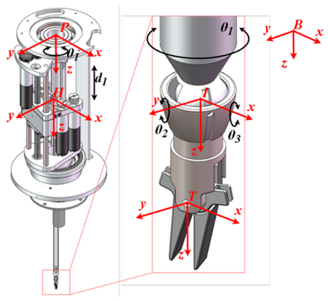
As illustrated in Figure 4, to characterize the geometric errors present in the surgical robotic system and to describe its kinematic relationships, a kinematic model was established using the standard Denavit–Hartenberg (DH) parameterization method.
The DH parameters corresponding to each link within a single module are listed in Table 1.
Based on the coordinate transformations between adjacent links, the homogeneous transformation matrix of the module was derived as T o c o b T o d o c .
T O c O b = [ cos θ 2 sin θ 2 0 0 sin θ 2 cos θ 2 0 0 0 0 1 d 1 0 0 0 1 ] T O d O c = [ 1 0 0 0 0 1 0 0 0 0 1 d 2 0 0 0 1 ]
which, after simplification, yielded the forward kinematic expression of the end-effector pose.
T o e o a = T o b o a T o c o b T o d o c T o e o d
= T r a n s ( a 1 C θ 1 , a 1 S θ 1 , 0 ) R o t ( z b , θ 2   ) T r a n s ( 0,0 , d 1 ) T r a n s ( 0,0 , d 2 )
R o t ( y , β ) R o t ( x , γ ) T r a n s ( 0,0 , d 3 )
Once the forward kinematic model was obtained, the influence of actuation errors on the end-effector output was further analyzed. Under ideal conditions, the end-effector pose x was uniquely determined by the joint variables q, such that:
x = f ( q )
However, in practical systems, joint variables were inevitably subject to perturbations Δq due to machining inaccuracies, assembly deviations, as well as elastic deformation and friction-induced hysteresis in cable-driven transmissions. These perturbations resulted in deviations in the end-effector pose Δx.
To describe the propagation of errors within the system, a first-order linear approximation based on the Jacobian matrix was introduced:
Δ x = J ( q ) Δ q
where J(q) denotes the Jacobian matrix at the current configuration, Δq represents the actuation-side errors, and Δx corresponds to the resulting end-effector pose errors. This relationship indicates that small input errors are transmitted to the end-effector through the kinematic mapping and may be amplified or coupled depending on the system configuration.
For the cable-driven system investigated in this study, joint errors originated not only from geometric parameter deviations but also from actuation uncertainties induced by cable elasticity, nonlinear friction, and hysteresis effects. Consequently, the end-effector error can be interpreted as the superposition of multiple error sources propagated through Jacobian mapping. This formulation provided a theoretical foundation for subsequent error modeling and compensation strategies.

2.2.3. Structural Deflection Modeling

In the conventional kinematic modeling of minimally invasive surgical robots, all links and joints are typically assumed to be ideal rigid bodies. However, during actual operation, the routing tube and supporting structures at the distal end generally exhibit high slenderness ratios, making them prone to bending deformation under the combined effects of cable tension and external loading [19]. Such structural deformation causes deviations in both position and orientation of the end-effector from the predictions of the ideal kinematic model, thereby introducing additional geometric errors [20]. Moreover, the deflection not only alters the spatial configuration of the structure but also modifies the effective transmission path and force distribution of the cables, resulting in coupled effects on the end-effector pose. Therefore, prior to analyzing cable-driven transmission errors, the deflection characteristics of the robot structure and distal routing tube were modeled to provide a foundation for subsequent error compensation.
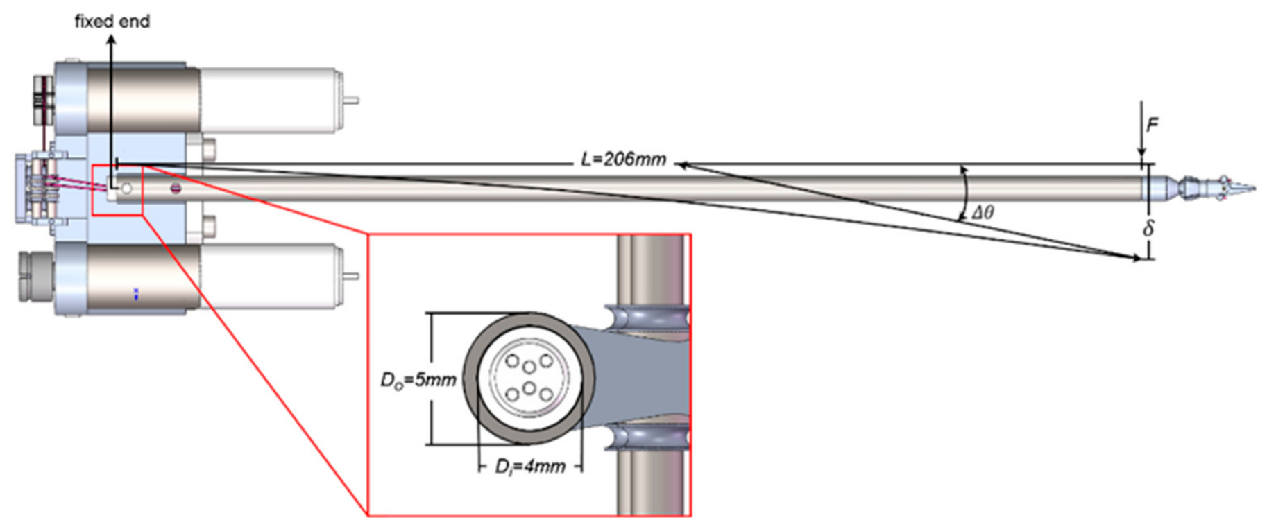
The medical steel tube connected to the end-effector (Figure 5) was simplified as a cantilever beam. Its geometric parameters were defined as: length L = 206 mm, outer diameter Do = 5 mm, and inner diameter Di = 4 mm, forming a hollow circular cross-section. According to classical beam theory, the deflection was primarily induced by bending and axial loads.
The second moment of area I for the hollow circular cross-section was expressed as:
I = π 64 ( D o 4 D i 4 )
When a radial load F was applied at the free end, the maximum deflection of the cantilever beam was given by:
δ = F L 3 3 E I
where E denotes the Young’s modulus.
Because the routing tube was rigidly connected to the end-effector, structural deflection resulted in both translational displacement and angular deviation. The angular deflection at the free end was approximated as:
Δ θ = δ L = F L 2 2 E I
indicating that the bending angle was proportional to the applied load and the square of the beam length. When the cable tension distribution was non-uniform, cables with higher tension exerted larger forces along their respective directions, inducing directional angular deviations Δθ, which affected the orientation of the end-effector.
For the three cable-driven actuators, the individual cable tensions F1, F2, and F3 were mapped to an equivalent resultant bending moment:
M z = i = 1 3 F i r sin ( ϕ i )
where r represents the effective radius of the cable routing path. This bending moment induced an angular deflection about the corresponding axis:
Δ θ z = M z L E I
Thus, the overall structural deflection was expressed as the combined effect of cable-induced moments and external loading.
Δ θ e f f = L E I i = 1 3 F i r sin ( ϕ i )
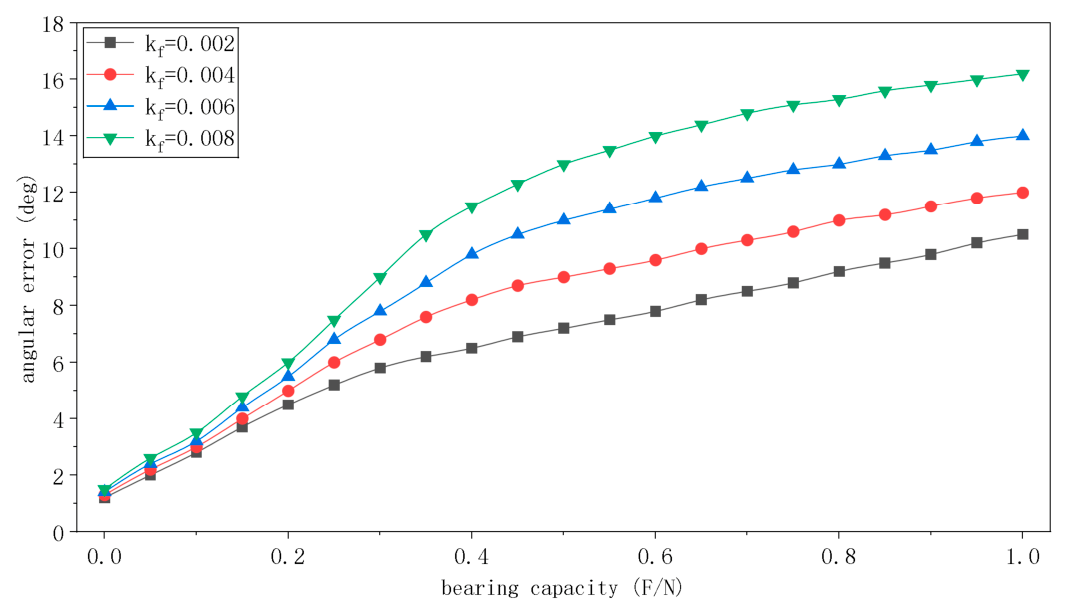
Based on the established flexible-link and routing-tube deflection model, simulations were conducted under varying equivalent stiffness conditions to evaluate the influence of deflection coefficients on the angular error of the end-effector (Figure 6).
The results showed that the end-effector error increased approximately linearly with increasing structural compliance. This trend indicates that structural deflection contributes significantly to positioning errors and cannot be neglected in the accuracy analysis of minimally invasive surgical robots.

2.2.4. Establishment of the LuGre Friction Model for Cable-Driven Systems

To accurately characterize the friction behavior of steel cables during motion, the LuGre dynamic friction model was introduced. Compared with conventional Coulomb friction models, the LuGre model is capable of describing static friction, dynamic friction, and the velocity-dependent Stribeck effect while incorporating internal state variables to represent the elastic behavior of microscopic contact interactions.
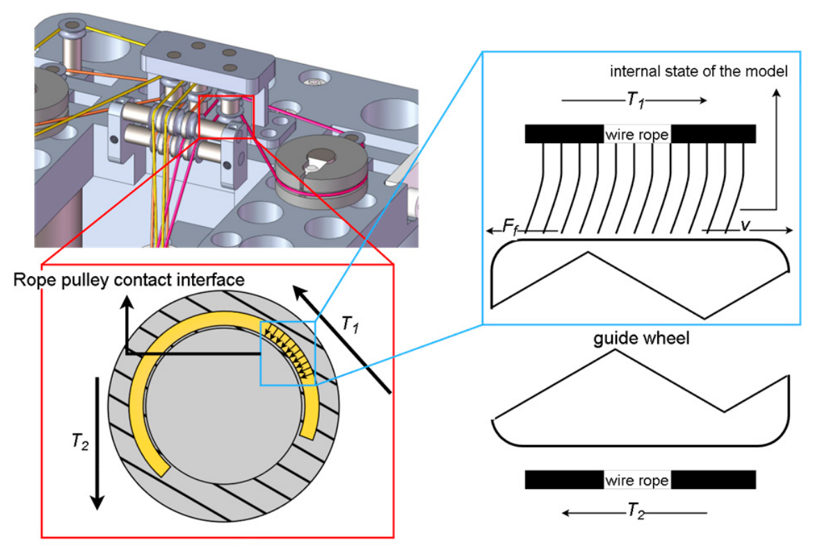
As illustrated in Figure 7, the cable forms a contact interface with the surface of the guiding pulley in the cable-driven system. To model the frictional behavior at this interface, the LuGre formulation was applied.
In this model, the pulley surface was treated as a rigid substrate, while the cable–pulley contact interface was represented as an ensemble of microscopic elastic bristles. The internal state variable z described the average deflection of these bristles and reflected the stick–slip condition of the contact interface.
When relative motion occurred between the cable and the pulley, a relative velocity v was generated, causing deformation of the bristles and resulting in a friction force Ff. This friction force introduced a tension difference between the two sides of the cable, i.e., T1 ≠ T2, leading to transmission errors and hysteresis effects.
The LuGre model was formulated as follows:
State equation:
d z d t = v | v | g ( v ) z
where g(v) denotes the Stribeck function, describing the variation of friction with velocity. In the present system, the cable diameter was 0.3 mm, and the operating velocity ranged from 0.01 to 0.1 m/s, corresponding to the low-speed regime where the Stribeck effect is prominent. Therefore, the LuGre model is well-suited for capturing friction-induced hysteresis and stick–slip phenomena in the cable-driven system.
The Stribeck curve was expressed as:
g ( v ) = F c + ( F s F c ) exp ( ( v v s ) 2 )
Friction force equation:
F = σ 0 z + σ 1 d z d t + σ 2 v
where σ0 denotes the bristle stiffness, σ1 represents the damping coefficient of the internal state, and σ2 is the viscous friction coefficient.
The complete LuGre model was therefore expressed as the combination of the state and output equations above.
{ d z d t = v | v | F c + ( F s F c ) exp ( ( v v s ) 2 ) z F f = σ 0 z + σ 1 d z d t + σ 2 v
From the model, it can be inferred that as v → 0, the friction force approaches the static friction limit Fs, under which stick–slip phenomena may occur. This implies that even at low motor speeds, excessive static friction may cause motion stagnation or delayed response at the end-effector, consistent with the observed behavior of the prototype system. The direct output of the LuGre model is the friction force Ff, which must be further mapped to kinematic quantities, including cable displacement ΔL and angular deviation Δθ.
The displacement-to-angle mapping was expressed as:
Δ θ = Δ L r e f
The cable elongation ΔL can be expressed as a function of the friction-induced force:
Δ L = F K = F L E A
where K denotes the equivalent stiffness of the cable. In this study, a φ 0.3   m m , 7*7 steel wire rope was used, with an elastic modulus E 2.0 × 10 11   P a and a cross-sectional area A = π ( d 2 ) 2 = 7.07 × 10 8   m 2 . As the cable length of the equivalent linear stiffness was approximately L = 0.5   m , the equivalent linear stiffness was approximately K 2.8 × 10 4   N / m .
Based on the above relationships, the angular error could be derived as:
Δ θ = Δ L r e f = F K r e f
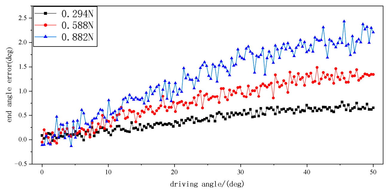
To evaluate the applicability of the proposed model under different loading conditions, external loads with varying masses were applied to the end-effector, and MATLAB 2020a simulations were conducted. The variation of end-effector angular error with respect to the driving angle under different load conditions is shown in Figure 8.
The results indicate that under low-load conditions, the system error was primarily dominated by friction effects, with relatively small magnitude and smooth variation. As the load increased, cable tension increased correspondingly, and the deflection of the routing tube became more pronounced. Consequently, the error curves exhibited a clear nonlinear growth trend. Further analysis showed that the ascending segments of the error curves reflected the hysteresis characteristics described by the LuGre model, whereas the overall offset increase corresponded to the structural deflection induced by reduced equivalent stiffness. These results demonstrate that the error sources in cable-driven systems exhibit strong multi-factor coupling and follow observable quantitative trends with varying load conditions.
In summary, the aforementioned models characterize system errors from three complementary perspectives: geometric relationships, structural compliance, and frictional nonlinearity, thereby providing a solid theoretical foundation for error source analysis. However, due to the presence of multi-source error coupling, parameter uncertainties, and pronounced nonlinear characteristics in cable-driven systems, reliance on purely mechanism-based models is insufficient to achieve the accurate prediction of real-world errors. Consequently, it is necessary to incorporate data-driven approaches to further model and compensate for residual errors.

2.3. DH Parameter Identification and Neural Network Compensation

Based on the preceding analysis of error mechanisms, it is evident that error sources in cable-driven systems are inherently complex and strongly coupled, making it difficult for any single mechanistic model to fully capture the actual error behavior. Among the established models, the DH-based kinematic model provides an ideal reference framework for error quantification by enabling a direct comparison between the theoretical predictions and actual outputs. Meanwhile, the structural deflection model and the LuGre friction model reveal the underlying trends and dominant influencing factors of error variation, thereby offering guidance for the selection of compensation variables.
Accordingly, in this section, DH parameter identification was first performed based on experimental data to correct geometric errors in the rigid transmission chain. Building upon this foundation, an RBF neural network was further introduced to learn and approximate the residual nonlinear errors that could not be fully captured by the mechanistic models. In this way, a hybrid error compensation framework integrating mechanism-based analysis with data-driven modeling was established.

2.3.1. Identification of DH Error Parameters

In robotic kinematic modeling, the Denavit–Hartenberg (DH) parameters are used to describe the geometric relationships between adjacent links. In theory, these parameters can be directly determined from design dimensions and assembly configurations. However, in practical manufacturing and assembly processes, various sources of error inevitably arise, including machining inaccuracies (e.g., link length deviations and misalignment of mounting holes), assembly errors (e.g., joint zero-offset deviations and lack of parallelism or perpendicularity), and structural deformation (e.g., small elastic deformations introduced by flexible connections). These factors cause discrepancies between the nominal DH parameters PDH and the actual system, leading to deviations in the predicted end-effector pose. To improve positioning accuracy, an experimental calibration combined with parameter identification was performed to correct the DH parameters.
The actual DH parameters were expressed as:
P D H = P D H + P D H
where ∆PDH denotes the compensation term to be identified.
To ensure sufficient excitation and uniform coverage of the workspace, multiple sets of joint configurations q were selected. The overall error ε ( q ) was defined based on the deviation between the corrected model and the experimentally measured end-effector pose.
ε ( q ) = T r e a l ( q ) T i d e ( q ; P D H )
When the optimal compensation parameters ∆PDH were obtained, the corrected model T c o r r approached the actual pose T r e a l ( q ) acquired from the calibration setup:
T c o r r ( q ; P D H + P D H ) T r e a l ( q )
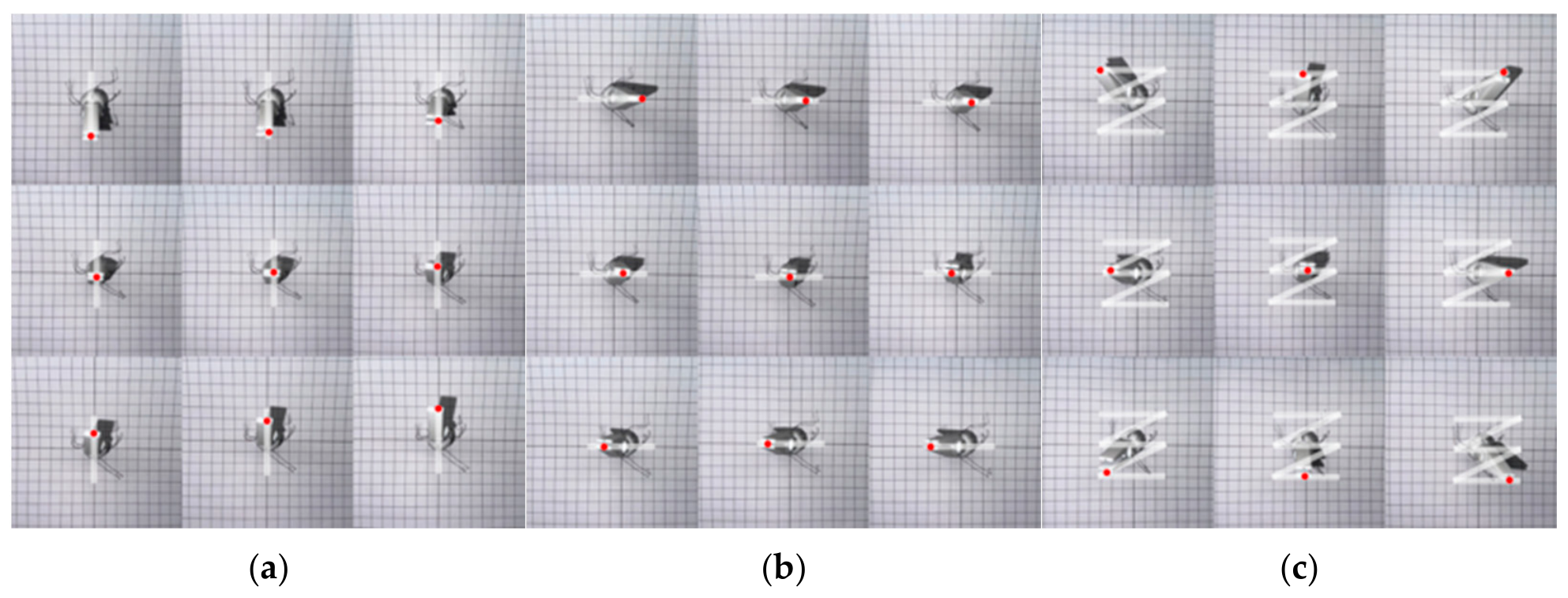
In the calibration experiment (Figure 9), both single-axis scanning and combined pose measurements were conducted for the pitch and yaw degrees of freedom of the end-effector. Specifically, when the yaw angle was fixed at 0°, the pitch angle was varied within θ p [ 40 ° , 40 ° ] ; conversely, when the pitch angle was fixed at 0°, the yaw angle was varied within θ y [ 40 ° , 40 ° ] . In addition, combined pose samples were collected at discrete configurations where θ p , θ y [ 40 ° , 0 ° , 40 ° ] . The experimental platform was developed based on a Beckhoff industrial control architecture. A Beckhoff C6930 controller was employed as the main control unit and communicated with the host computer through the EtherCAT protocol. Beckhoff EL3064 and EK1101 modules were used for analog signal acquisition and serial communication, respectively.
The master input device was a TS11-series Hall-effect joystick (Guangdong Tianshi), with a translational operating range of ±25° and a rotational range of ±20°. The EL3064 analog module was used to acquire the joystick signals and transmit them to the controller for voltage conversion and motion-command generation.
The actuation system consisted of Moons’ DCU13028-series motors equipped with S002&PG13C reducers and IE2-512 electromagnetic encoders. IPSO2041 drivers were employed for motor control and for position, velocity, and direction feedback acquisition. Communication between the controller and motor drivers was achieved through RJ45 serial communication via the EK1101 module.
An emergency stop switch was integrated into the system power bus to ensure operational safety during experimental testing.
During the experiment, a camera fixed on a tripod was used to record the motion of the end-effector. The projected coordinates of the end-effector trajectory were extracted from the captured images for pose measurement and error analysis. To reduce measurement disturbances, the camera position and imaging angle were kept fixed throughout the experiment.
Based on the measured data from the prototype system, the least-squares objective function for parameter identification was defined as:
J ( P D H ) = k = 1 N f ( q k ; P D H + P D H ) P r e a l ( q k ) 2
where f(⋅) denotes the forward kinematic mapping, and P r e a l ( q k ) represents the measured end-effector pose.
The error function was linearized around the current parameter estimate:
Δ p k = p r e a l ( q k ) f ( q k ; P D H ) J k P D H
where Jk is the Jacobian matrix with respect to the DH parameters at sample k.
J k = f ( q k ; P D H ) P D H
By stacking all samples, the least-squares solution was obtained as:
P D H = ( J T J ) 1 J T Δ P
The identified parameters were then incorporated into the kinematic model, resulting in a corrected model that more closely matched the measured end-effector poses.
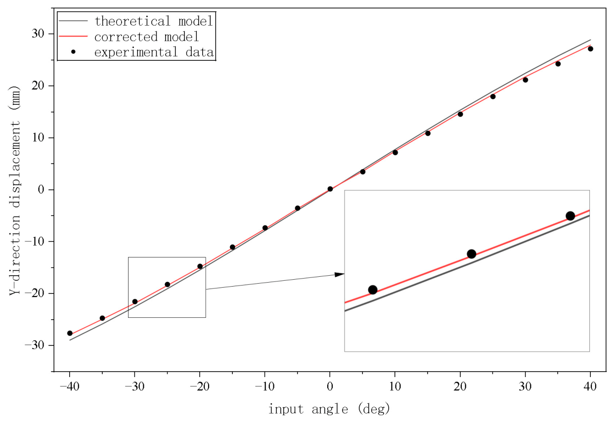
As shown in Figure 10, after DH parameter identification and correction, the predicted trajectory of the model was closer to the experimental data compared with the original theoretical model. This result indicates that the proposed parameter correction method improved the accuracy of the kinematic model to a certain extent.
However, the improvement in overall system accuracy remained limited. This is because the dominant error sources in the system originated from nonlinear effects associated with the cable-driven mechanism, including friction, elastic deformation, and transmission hysteresis. In comparison, geometric parameter errors contributed a relatively smaller proportion of the total error. Consequently, DH parameter correction alone was insufficient to fully compensate for the system inaccuracies.

2.3.2. Feedforward Neural Network Compensation

In the preceding sections, the error sources of the end-effector were systematically analyzed from both rigid structural characteristics and cable-driven transmission behavior. The LuGre dynamic friction model was introduced to characterize nonlinear errors arising from friction, hysteresis, and tension variation in the cable-driven process, while geometric errors in the rigid structure were compensated through DH parameter identification. These physics-based models provided a mechanistic interpretation of error generation and established a foundation for subsequent compensation strategies.
However, errors in cable-driven systems are not solely governed by friction and elasticity but also exhibit strong nonlinearity and time-varying characteristics. These include velocity-dependent friction behavior, varying mechanical responses under different operating conditions, and uncertainties introduced by environmental disturbances and structural coupling. Such complexities limit the capability of the LuGre model to fully capture all error characteristics. To address this limitation, a data-driven approach was incorporated. Specifically, a radial basis function (RBF) neural network was employed to learn the residual errors based on the physical prior provided by the LuGre model, thereby enabling high-accuracy compensation of nonlinear cable-driven errors.
The RBF neural network is a class of feedforward neural networks characterized by a simple structure, fast convergence, and strong nonlinear approximation capability. It consists of an input layer, a hidden layer, and an output layer. The hidden layer uses radial basis functions, typically Gaussian functions, as activation functions, where the Euclidean distance between input samples and center vectors serves as the input variable, reflecting the similarity between input features and hidden neurons. By adjusting the centers, widths, and output weights, the RBF network can effectively model highly nonlinear and time-varying relationships with a limited number of samples.
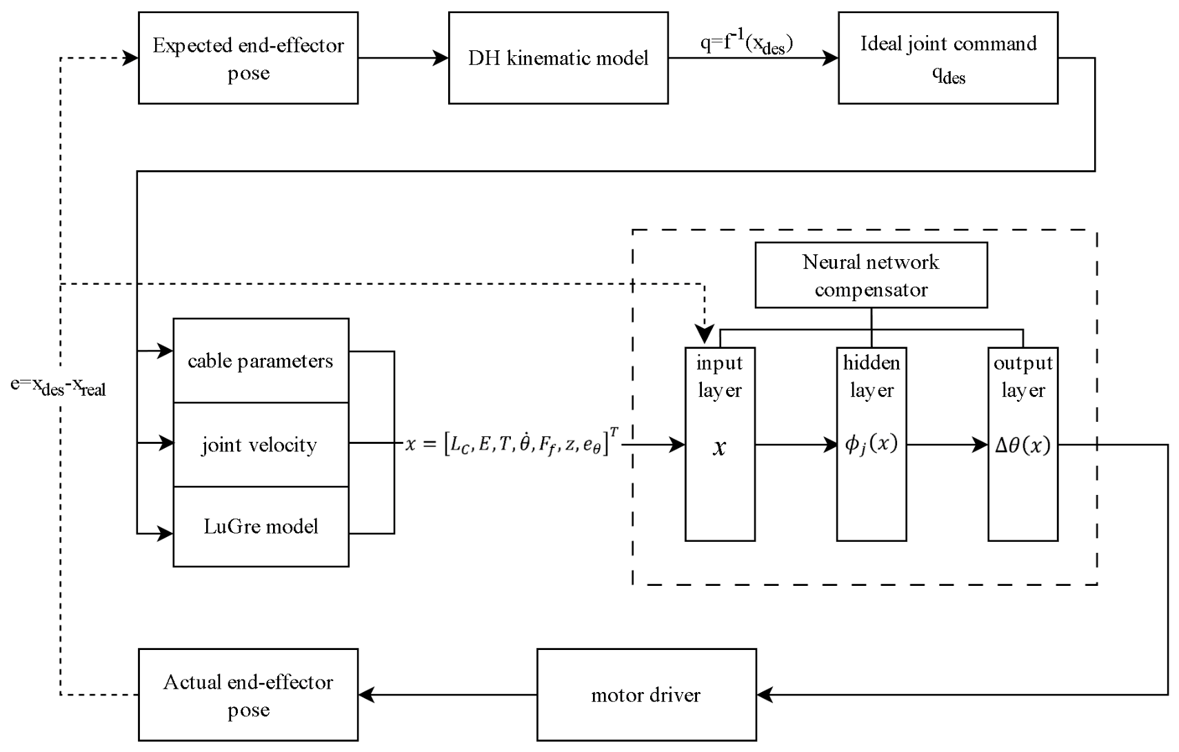
When applied to error compensation in the cable-driven surgical robot (Figure 11), the input layer incorporated cable-related parameters (length, elastic modulus, and tension) and system state variables (e.g., velocity and joint angle).
In addition, feature quantities derived from the LuGre model, including friction force F, internal state z, and angular error Δθ, were included to enhance model expressiveness. The hidden layer captured nonlinear relationships through radial basis functions, and the output layer provided predictions of end-effector pose deviations.
It should be noted that the proposed compensation strategy adopted a feedforward structure based on error modeling, without introducing real-time sensor feedback for conventional closed-loop control. In the present study, the compensation model was implemented in an offline feedforward manner based on experimentally measured error data. The term “quasi-closed-loop” refers to the use of measured end-effector deviations for constructing the compensation model, rather than the existence of a real-time sensor-feedback control loop during robot operation. However, by comparing the experimentally measured end-effector poses with the desired poses, an error feedback relationship was established offline, forming a quasi-closed-loop analysis framework based on measurement data.
Compared with conventional fully connected neural networks, RBF neural networks exhibit stronger local approximation capability and faster convergence characteristics, making them particularly suitable for nonlinear error compensation tasks with limited experimental datasets in cable-driven robotic systems. In addition, RBF-based approaches have demonstrated effectiveness in handling complex nonlinear behaviors such as friction-induced hysteresis, elastic deformation, and geometric uncertainties in robotic systems [21,22]. Furthermore, the RBF network demonstrated good robustness under limited training data conditions, enabling accurate predictions for unseen operating conditions. This property is particularly important in medical robotics, where data acquisition is often constrained, yet high accuracy must be maintained under varying environments.
In this study, the RBF neural network was constructed as follows:
Input layer: cable parameters (length, elasticity, tension), driving velocity, and LuGre-derived features (friction force F, internal state z, and angular error Δθ).
Hidden layer: Gaussian radial basis functions:
ϕ j ( x ) = exp ( x c j 2 2 σ J ˙ 2 )
where cj and σj denote the center and width of the j-th basis function.
Output layer:
Δ d ^ = j = 1 n w j ϕ j ( x )
where wj represents the weight, and Δ d ^ is the predicted end-effector error.
The training objective was defined as minimizing the mean squared error:
min w j d m Δ d ^ 2
The performance of the RBF network strongly depends on the selection of centers cj and widths σj. In this study, k-means clustering was employed to partition the input data and determine the centers of the basis functions. The widths were determined using an empirical formulation:
σ j = d m a x 2 M
where dmax denotes the maximum Euclidean distance among samples, and M is the number of basis functions. The weight vector W was determined using the least-squares solution:
W = Φ + T
where Φ + denotes the pseudoinverse of the basis function output matrix, and T is the target output vector.
To ensure robustness under unseen operating conditions (e.g., varying velocity, tension, or temperature), the dataset was divided into a training set (approximately 80%) and a test set (approximately 20%). Prior to training, input data were normalized, and the predicted outputs were transformed back to physical quantities through inverse normalization.
x n o r = x x m i n x m a x x m i n
Model performance was evaluated using the root mean square error (RMSE):
R M S E = 1 N k = 1 N d m ( k ) Δ d ^ ( k ) 2
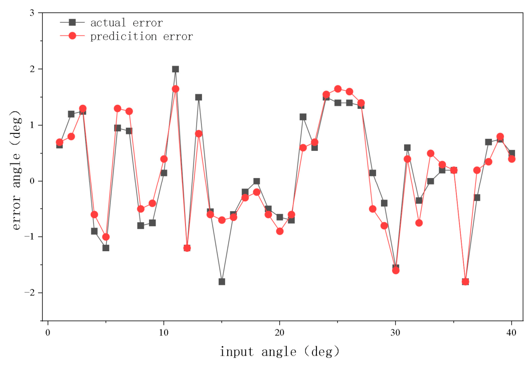
As shown in Figure 12, the results demonstrated that the RBF neural network effectively captured the nonlinear characteristics of cable-driven errors and provided accurate predictions of system error during operation.
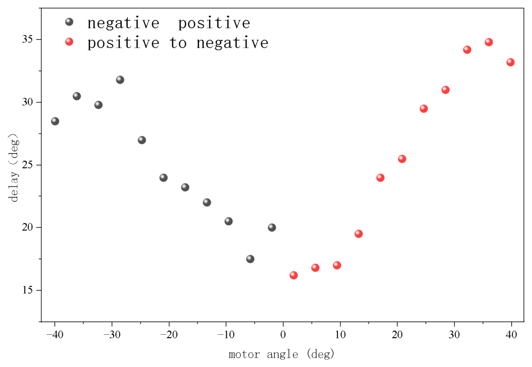
It should be noted that neural network models typically lack explicit analytical expressions, which limits interpretability and practical implementation in real-time systems. To improve model interpretability and reduce computational complexity during online compensation, the error function was further analyzed and extracted into an explicit form based on experimental data. For a single yaw degree of freedom of the end-effector within the normal operating range, experimental measurements and neural network predictions were analyzed (Figure 13).
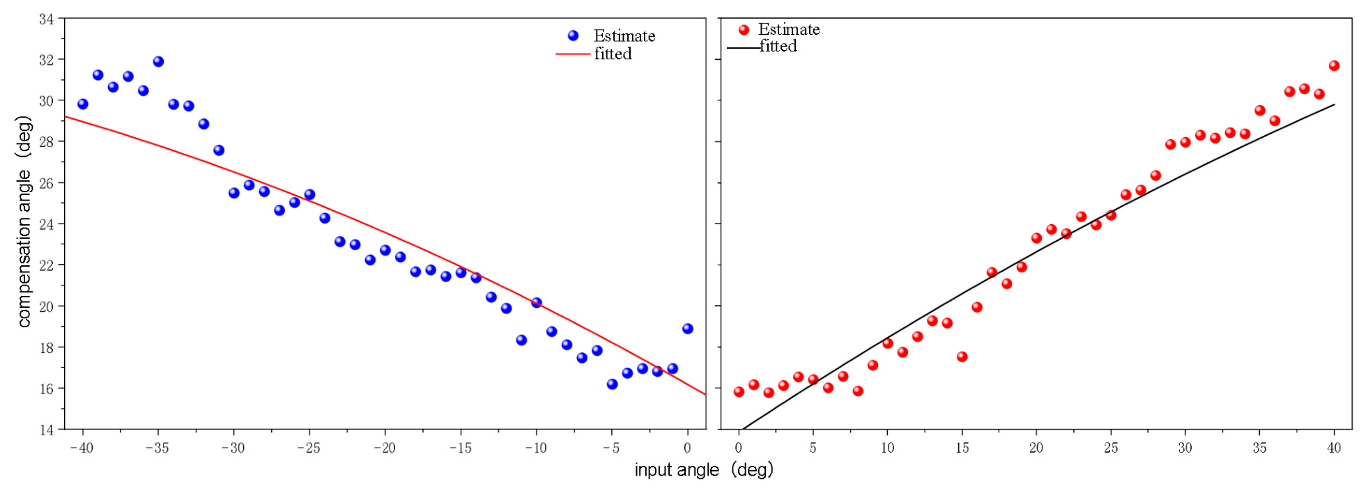
The results showed that for a single DOF, the error curves corresponding to positive and negative initial driving directions exhibited approximately symmetric characteristics. Within the operating range, both curves presented smooth and monotonic nonlinear trends. By fitting the error curves (Figure 14), it was found that they could be well approximated by quadratic polynomial functions within the studied range. These functions were then interpreted as equivalent explicit representations of the theoretical model and neural network predictions.
The equivalent error compensation model was expressed as:
Negative direction:
y = 0.0025 x 2 0.4196 x + 16.1841
Positive direction:
y = 0.0025 x 2 + 0.5975 x + 12.3667
It is important to note that due to differences in friction characteristics and tension distribution during forward and reverse motion, the error curves did not coincide under identical input angles. Therefore, a single error model was insufficient to describe both motion states.
To address this issue, a direction-dependent compensation strategy was adopted. Specifically, the positive-direction fitting function was applied during forward motion, while the negative-direction function was used during reverse motion. By introducing a motion-direction discrimination mechanism, the hysteresis-related errors were effectively reduced.
In summary, based on rigid-body modeling, cable-driven dynamics analysis, and neural network-based learning, the error model was further transformed into an explicit equivalent form using experimental data. A quadratic polynomial model capable of compensating the actual errors of the minimally invasive surgical robot was ultimately obtained.

3. Results

3.1. Comparative Error Experiments

To evaluate the effectiveness of the proposed error compensation method in improving the end-effector accuracy of the cable-driven surgical robot, a set of controlled comparative experiments was designed and conducted. The experiments were performed on the same robotic platform under identical driving inputs and operating conditions, comparing two control strategies: without compensation and with the proposed error compensation. During the experiments, identical target angle sequences were applied at the actuation side, and the robot executed the same motion trajectories in both cases. In Group A, no error compensation was introduced, and control was implemented solely based on the nominal kinematic model. In Group B, the proposed equivalent error compensation model was incorporated, and the driving angles were modified through feedforward correction.
The system performance was evaluated by comparing the end-effector position response, response delay during motion reversal, and steady-state error under the two conditions.

3.2. Experimental Results Analysis

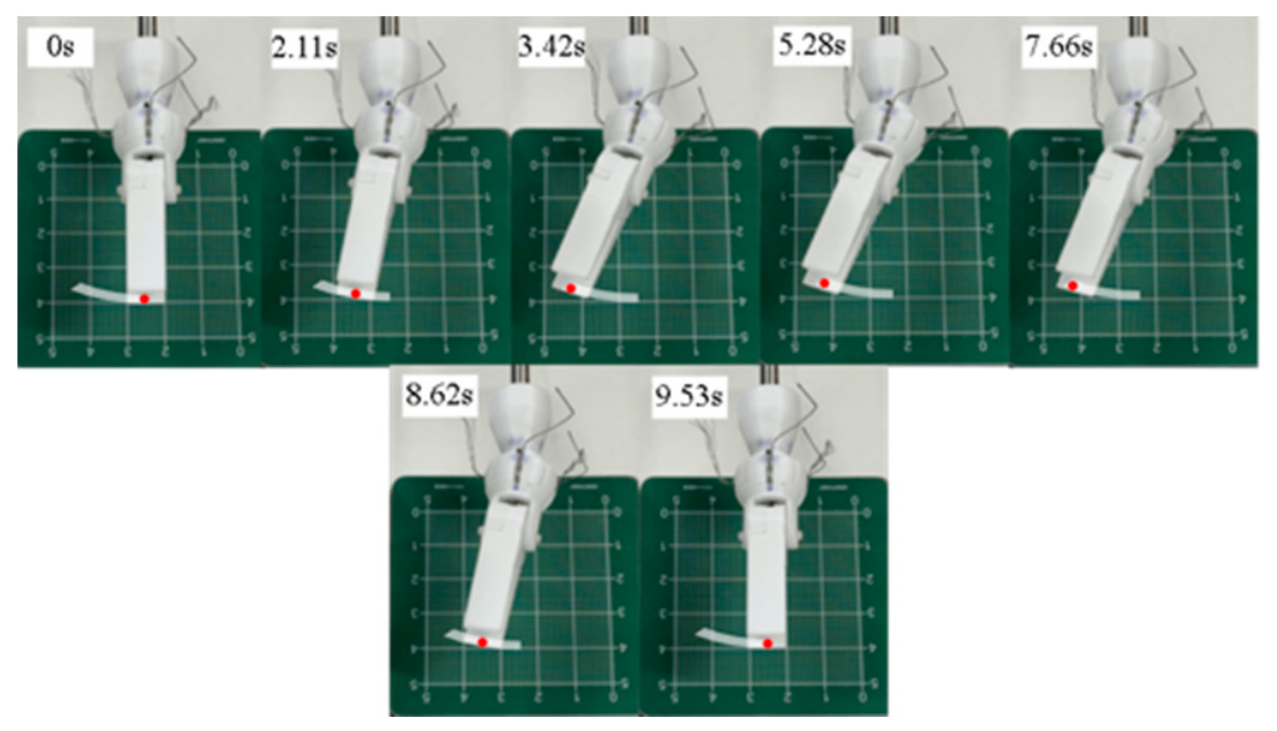
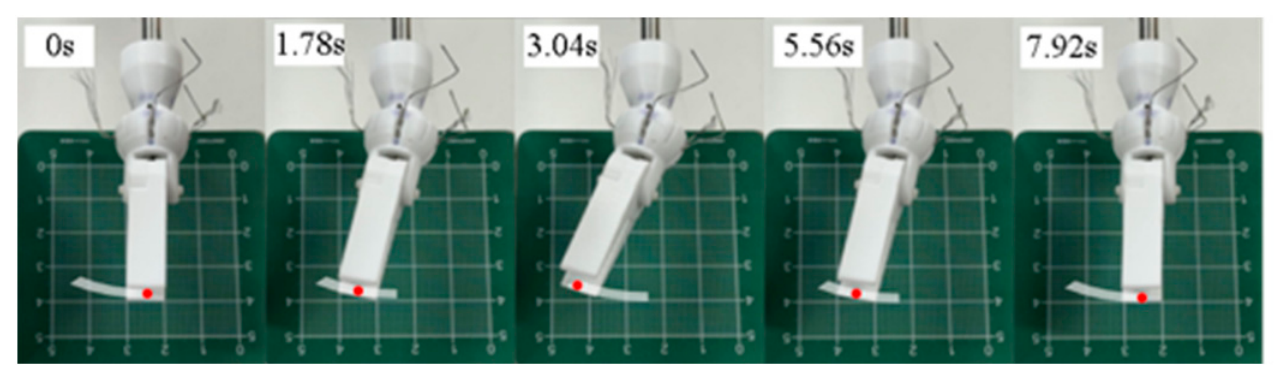
The experimental results are presented in Figure 15 and Figure 16.
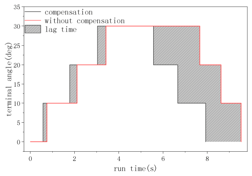
Without error compensation, the end-effector exhibited a pronounced hysteresis effect during motion reversal, and the error accumulated with increasing driving angle. After applying the proposed compensation method, the end-effector reached the target position more rapidly, and the reversal error was significantly reduced. A visual comparison of the end-effector position (Figure 17) showed that under identical driving inputs, the positioning deviation of the compensated system was smaller than that of the uncompensated system, confirming the effectiveness of the proposed method in practical operation.
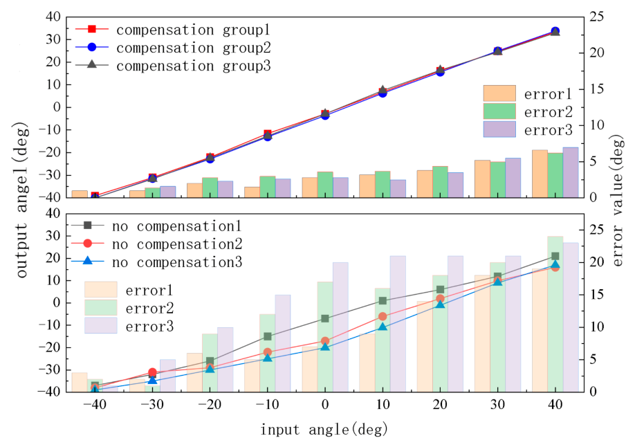
To further assess the reliability of the results, repeated experiments were conducted along the same trajectory, as shown in Figure 18.
The quantitative results demonstrated that without compensation, the system exhibited significant hysteresis during motion reversal, and the error increased cumulatively with the driving angle. Over the entire motion range, the uncompensated system showed a maximum error of approximately 34.63°, an average error of approximately 23.57°, and a root mean square error (RMSE) of 25.41°, indicating substantial nonlinear deviation and path-dependent behavior.
After applying the error compensation, the motion response of the end-effector improved significantly. The maximum error decreased to approximately 21.13°, the average error was reduced to approximately 15.62°, and the RMSE decreased to 16.48°. Compared with the uncompensated case, the maximum error was reduced by approximately 39.0%, the average error by 33.7%, and the RMSE by 35.1%.
Furthermore, comparison of the end-effector positions at identical time instants (Figure 16) showed that the compensated system output more closely followed the desired trajectory under the same input conditions. The hysteresis region during motion reversal was significantly reduced, and the error curves exhibited smoother profiles.
These results indicate that the proposed RBF neural network-based error compensation method effectively suppresses nonlinear errors and hysteresis effects in cable-driven systems, thereby significantly improving the dynamic response performance and positioning accuracy of the robotic system.

4. Conclusions

This study addressed the end-effector positioning deviation and dynamic hysteresis in cable-driven minimally invasive surgical robots arising from geometric inaccuracies, frictional hysteresis, and structural compliance coupling. By integrating mechanism-based modeling with data-driven compensation and validating the approach experimentally, the following conclusions were established:
  • Geometric calibration via DH parameter identification effectively corrected deviations in the rigid transmission chain, bringing model predictions into closer agreement with measured poses and reducing positioning errors induced by assembly imperfections;
  • The LuGre dynamic friction model successfully characterized the nonlinear and direction-dependent friction behavior at the cable–pulley interface, providing a physically grounded description of hysteresis and transmission asymmetry in cable-driven systems;
  • The RBF neural network-based compensation framework accurately learned residual nonlinear errors not captured by the physics-based model, enabling precise representation and compensation of complex error characteristics arising from frictional hysteresis and structural coupling;
  • Experimental validation demonstrated substantial performance gains: under identical control inputs, the compensated system achieved markedly improved positioning accuracy and dynamic response, with a pronounced reduction in hysteresis during motion reversal, confirming its effectiveness in mitigating path-dependent errors.
Overall, the proposed hybrid framework—combining kinematic calibration, physics-informed modeling, and data-driven residual learning—provides a robust and practically viable solution for high-precision control of cable-driven surgical robots. The results underscore its potential to enhance both accuracy and stability in demanding minimally invasive surgical applications.

Author Contributions

Conceptualization, C.Y.; Methodology, C.Y.; Software, Y.S.; Validation, Y.S.; Formal analysis, Y.S.; Investigation, C.Y.; Resources, S.Y. and C.Y.; Data curation, Y.S.; Writing—original draft, Y.S.; Writing—review & editing, S.Y., C.Y., H.L. and C.S.; Supervision, S.Y., C.Y. and H.L.; Project administration, C.Y. All authors have read and agreed to the published version of the manuscript.

Funding

This research received no external funding.

Data Availability Statement

Data are contained within the article.

Conflicts of Interest

The authors declare no conflict of interest.

Abbreviations

The following abbreviations are used in this manuscript:
MISMinimally Invasive Surgery
DOFDegree of Freedom
DHDenavit–Hartenberg
RBFRadial Basis Function
RMSERoot Mean Square Error

References

  1. Jeganathan, R.J.; Jegasothy, R.; Sia, T.W. Minimally invasive surgery: A historical and legal perspective on technological transformation. J. Robot. Surg. 2025, 19, 408. [Google Scholar] [CrossRef] [Scilit] [PubMed]
  2. Saridogan, E.; Antoun, L.; Bouwsma, A.V.E.; Clark, T.J.; Sardo, A.D.S.; Huirne, J.; Walker, T.S.; Tanos, V. European Society for Gynaecological Endoscopy (ESGE) Good Practice Recommendations on surgical techniques for removal of fibroids: Part 1 abdominal (laparoscopic and open) myomectomy. Facts Views Vis. ObGyn 2024, 16, 263–280. [Google Scholar] [CrossRef] [Scilit] [PubMed]
  3. Shinichi, Y.; Marie, H.; Noriko, I.; Masuda, T.; Tokunaga, M.; Kinugasa, Y. Robotic-assisted Surgery: Expanding Indication to Colon Cancer in Japan. J. Anus Rectum Colon 2022, 6, 77–82. [Google Scholar]
  4. Norihiko, I.; Go, W.; Yasumitsu, H.; Inaki, N.; Kawachi, K.; Oda, M. Robotic dexterity: Evaluation of three-dimensional monitoring system and non-dominant hand maneuverability in robotic surgery. J. Robot. Surg. 2007, 1, 231–233. [Google Scholar]
  5. Dragone, D.; Donadio, F.F.; Mirabelli, C.; Cosentino, C.; Amato, F.; Zaffino, P.; Spadea, M.F.; La Torre, D.; Merola, A. Design and Experimental Validation of a 3D-Printed Embedded-Sensing Continuum Robot for Neurosurgery. Micromachines 2023, 14, 1743. [Google Scholar] [CrossRef] [Scilit] [PubMed]
  6. Jason, B.; Giulio, P.; Dario, R.; Trevisani, A. Model predictive control for path tracking in cable driven parallel robots with flexible cables: Collocated vs. noncollocated control. Multibody Syst. Dyn. 2023, 58, 47–81. [Google Scholar] [CrossRef] [Scilit]
  7. Begey, J.; Cuvillon, L.; Lesellier, M.; Gouttefarde, M.; Gangloff, J. Dynamic Control of Parallel Robots Driven by Flexible Cables and Actuated by Position-Controlled Winches. IEEE Trans. Robot. 2019, 35, 286–293. [Google Scholar] [CrossRef] [Scilit]
  8. Jamshidifar, H.; Fidan, B.; Gungor, G.; Khajepour, A. Adaptive Vibration Control of a Flexible Cable Driven Parallel Robot. IFAC-Pap. 2015, 48, 1302–1307. [Google Scholar] [CrossRef] [Scilit]
  9. Xiao, B.; Alamdar, A.; Song, K.; Ebrahimi, A.; Gehlbach, P.; Taylor, R.H. Delta Robot Kinematic Calibration for Precise Robot-Assisted Retinal Surgery. In Proceedings of the 2022 International Symposium on Medical Robotics (ISMR); IEEE: New York, NY, USA, 2022. [Google Scholar]
  10. Zhang, W.; Zhang, F.; Zhang, J.; Zhang, S.; Zhang, J.; Zhang, J.; Sun, H.; Waters, K.E.; Ma, H. Research and analysis of an enhanced genetic algorithm identification method based on the LuGre model. PLoS ONE 2025, 20, e0322844. [Google Scholar] [CrossRef] [Scilit] [PubMed]
  11. Huang, H.; Li, Z.; Wang, S. Neural-network-based modeling and control of robotic manipulators. IEEE Trans. Ind. Electron. 2017, 64, 3892–3901. [Google Scholar]
  12. Brunton, S.L.; Noack, B.R.; Koumoutsakos, P. Machine learning for fluid mechanics. Annu. Rev. Fluid Mech. 2020, 52, 477–508. [Google Scholar] [CrossRef] [Scilit]
  13. Veitschegger, W.K.; Wu, C.-H. Robot calibration and compensation. IEEE J. Robot. Autom. 1988, 4, 643–656. [Google Scholar] [CrossRef] [Scilit] [PubMed]
  14. Park, C.; Kim, D.; Do, H.; Choi, T.; Choi, D.; Kim, B. The Effects of Design Parameters on the Mechanical Precision of an End Effector on a Parallel Kinematic Robot. J. Inst. Control. Robot. Syst. 2016, 22, 847–852. [Google Scholar] [CrossRef] [Scilit]
  15. Hanifzadegan, M.; Nagamune, R. Tracking and Structural Vibration Control of Flexible Ball–Screw Drives with Dynamic Variations. IEEE/ASME Trans. Mechatron. 2015, 20, 133–142. [Google Scholar] [CrossRef] [Scilit]
  16. Ryota, W.; Motoyasu, T. Principle of object support by Rope deformation and its application to Rope climbing by snake robot. Adv. Robot. 2023, 37, 591–602. [Google Scholar] [CrossRef] [Scilit]
  17. Lindenroth, L.; Housden, R.J.; Wang, S.; Back, J.; Rhode, K.; Liu, H. Design and Integration of a Parallel, Soft Robotic End-Effector for Extracorporeal Ultrasound. IEEE Trans. Biomed. Eng. 2020, 67, 2707. [Google Scholar] [CrossRef] [Scilit] [PubMed]
  18. Piao, J.; Kim, E.-S.; Choi, H.; Moon, C.-B.; Choi, E.; Park, J.-O.; Kim, C.-S. Indirect Force Control of a Cable-Driven Parallel Robot: Tension Estimation using Artificial Neural Network trained by Force Sensor Measurements. Sensors 2019, 19, 2520. [Google Scholar] [CrossRef] [Scilit] [PubMed]
  19. Tanev, T.K.; Cammarata, A.; Marano, D.; Sinatra, R. Elastostatic Model of a New Hybrid Minimally-Invasive-Surgery Robot. In Proceedings of the 14th IFToMM World Congress, Taipei, Taiwan, 25–30 October 2015; pp. 449–458. [Google Scholar]
  20. Dupont, P.E.; Simaan, N.; Choset, H.; Rucker, C. Continuum Robots for Medical Interventions. Proc. IEEE. Inst. Electr. Electron. Eng. 2022, 110, 847–870. [Google Scholar] [CrossRef] [Scilit] [PubMed]
  21. Zhang, F.; Shang, W.; Li, G.; Cong, S. Calibration of geometric parameters and error compensation of non-geometric parameters for cable-driven parallel robots. Mechatronics 2021, 77, 102595. [Google Scholar] [CrossRef] [Scilit]
  22. Wang, Z.; Liu, C.; Qian, S.; Wang, D.; Wei, X.; Yu, X. Tracking control with external force self-sensing ability based on position/force estimators and non-linear hysteresis compensation for a backdrivable cable-pulley-driven surgical robotic manipulator. Mech. Mach. Theory 2023, 183, 105259. [Google Scholar] [CrossRef] [Scilit]
Figure 1. Prototype of minimally invasive surgical robot.
Machines 14 00584 g001
Figure 2. Minimally invasive surgical robot single module flexible cable part.
Machines 14 00584 g002
Figure 3. Sources of structural errors in cable-driven mechanisms.
Machines 14 00584 g003
Figure 4. Establishment of single module coordinates for surgical robots.
Machines 14 00584 g004
Figure 5. Stress analysis of actuator steel pipe deflection.
Machines 14 00584 g005
Figure 6. Analysis of the influence of deflection coefficient variation on end angle.
Machines 14 00584 g006
Figure 7. Schematic diagram of the LuGre model for flexible cable-guided pulley contact interface.
Machines 14 00584 g007
Figure 8. Trend of end angle error variation under light, medium, and heavy loads.
Machines 14 00584 g008
Figure 9. Calibration experiment: (a) calibration experiment pitch group; (b) yaw group; (c) coupling group.
Machines 14 00584 g009
Figure 10. Comparison curve of end position before and after DH parameter correction.
Machines 14 00584 g010
Figure 11. Neural network compensation process.
Machines 14 00584 g011
Figure 12. Neural network compensation results.
Machines 14 00584 g012
Figure 13. Neural network prediction results.
Machines 14 00584 g013
Figure 14. Error curve fitting results.
Machines 14 00584 g014
Figure 15. Experimental Group A exhibits uncompensated pendulum motion.
Machines 14 00584 g015
Figure 16. Experimental Group B introduces error compensation for yaw motion.
Machines 14 00584 g016
Figure 17. Comparison of end execution angle between Group A and Group B at the same time.
Machines 14 00584 g017
Figure 18. Comparison of repeated experiments.
Machines 14 00584 g018
Table 1. Joint parameters of single module of minimally invasive surgical robot.
Serial Number TypeVariableActionScope
1revolute pair θ 1 rotate around Z ± 120 °
2translational pair d 1 Move along Z ± 30   m m
3revolute pair θ 2 rotate around Y ± 35 °
4revolute pair θ 3 rotate around X ± 35 °
Disclaimer/Publisher’s Note: The statements, opinions and data contained in all publications are solely those of the individual author(s) and contributor(s) and not of MDPI and/or the editor(s). MDPI and/or the editor(s) disclaim responsibility for any injury to people or property resulting from any ideas, methods, instructions or products referred to in the content.