1. Introduction
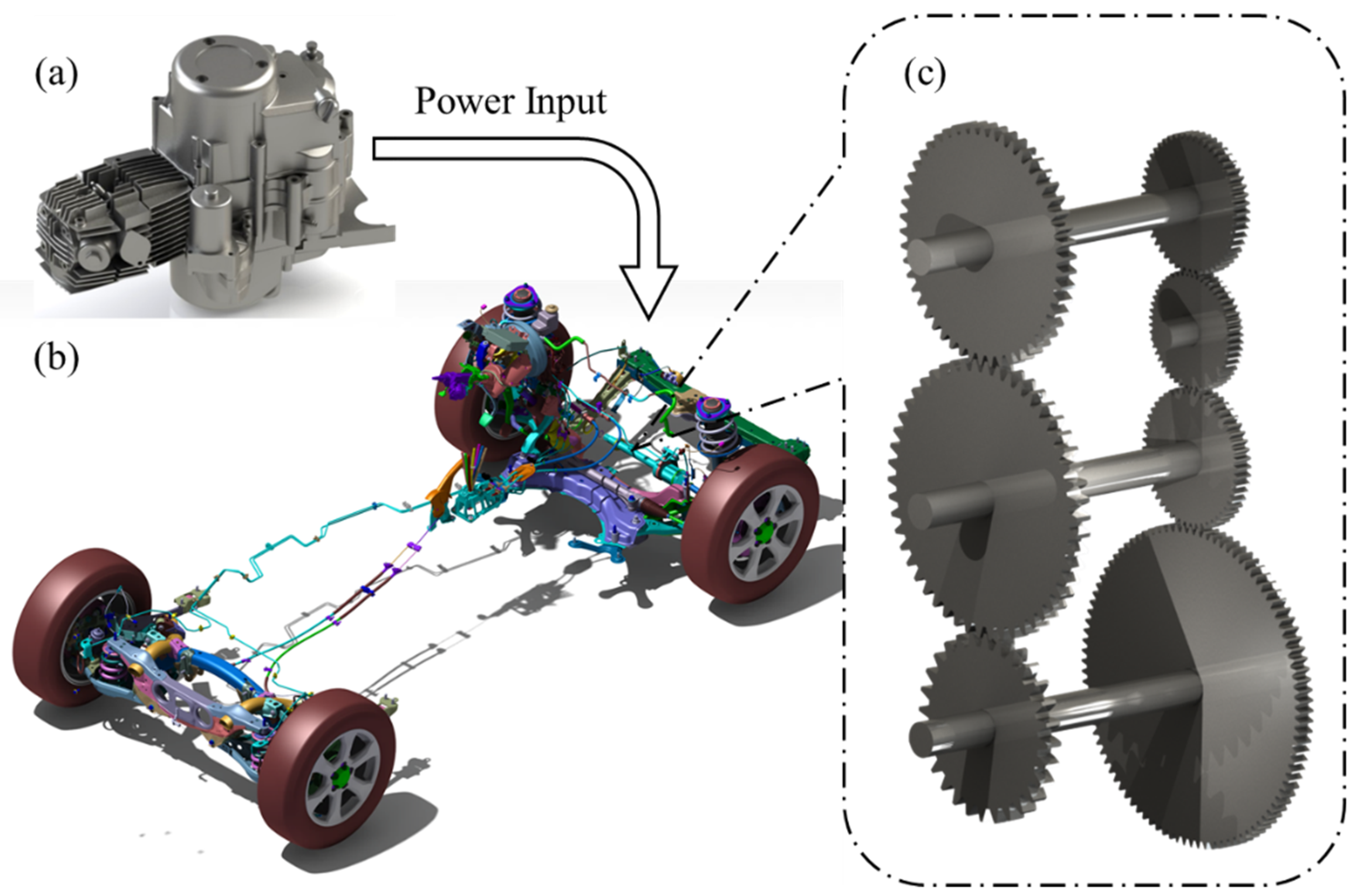
The vehicle driveline is an essential component that ensures the vehicle is in motion, which transfers power from the engine through the crankshaft to the differential, by adjusting different levels of gears, and finally via the drive shaft into each wheel, as shown in
Figure 1a,b [
1]. A power shift gearbox is a torsional vibration system with multiple DOF (degrees of freedom, DOF), which is one of the key components to adjust the output torque and rotational speed from the engine, including gears, clutches, axles, and the box, with the interior simplified as shown in
Figure 1c. Yet, due to various factors, such as the ignition stroke, unbalanced inertial forces, clearances, and uneven gear meshing, the excitation torque from the engine is not constant [
2], and the rotating speed of the gears in the driveline varies over time [
3,
4].
Due to the periodic operation of the engine, the resonance phenomenon occurs when a single harmonic component of the torsional excitation frequency coincides with an arbitrary natural frequency of the driveline [
5]. Severe resonance may even lead to disastrous accidents, such as crankshaft and drive shaft breakage [
6], elastic coupling destruction [
7], screw looseness and breakage [
8], and some other NVH [
9] problems.
To prevent these incidents above, numerous studies have been progressively explored from key component analysis to system vibration control analysis. Traditional studies mainly focus on the fundamental components of drivelines, including drive shafts and gears, to investigate their static performance [
10]. In terms of the drive shafts, Yashwant Singh Bisht et al. [
11] designed and analyzed a novel composite drive shaft specifically for vehicle applications, considering multiple characteristics such as weight, strength, stiffness, and durability. Yefa Hu et al. [
12] established a torsional experimental platform to measure the torsional stiffness of carbon fiber-reinforced plastic drive shafts, and a composite drive shaft with different stacking sequences and angles was designed and analyzed using the finite element method. The study of gears extends from structural strength to dynamic meshing behavior. Zhiheng Feng and Chaosheng Song [
13] designed a gear meshing model and a nonlinear dynamic model, and analyzed the effects of geometric parameters on the gear bending strength based on the models above. Joao D.M. Marafona et al. [
14] investigated the effect of different contact lengths between gears on the meshing stiffness and designed an algorithm for constant gear meshing stiffness based on the gear safety factor and meshing efficiency. As the study of dynamic characteristics in the driveline has advanced, it has come to consider the influence of damping on structural vibration behavior. Accordingly, the design of torsional vibration dampers has developed and been introduced into the driveline [
6]. Mario Lázaro [
15] proposed a new closed-form approximation formula, deriving the quadratic eigenvalues from damped dynamic equations and explicitly including the non-diagonal entries of the modal damping matrix in the approximate solution for the first time. Milata Michal et al. [
6] designed and embedded a novel torsional vibration damper in the crankshaft according to the counterweight and analyzed the crankshaft for Von-Mises stresses. Hasmet Cagri Sezgen and Mustafa Tinkir [
16] adopted a hybrid damping approach to design and optimize a double mass rubber and viscous torsional damper to reduce torsional vibration in the crankshaft system of an internal combustion engine. Based on the study of the mechanical system mentioned above, Kun Liu et al. [
17] took further consideration of electromagnetic effects and control systems. The modal characteristics of an electric powertrain incorporating electromagnetic effects were investigated by utilizing the parameter matrix of the system state space equation. The influence of the electromagnetic effect on gear loading and motor current under impact loading was analyzed. It refines the theoretical methods for the design of electromechanical systems and the analysis of dynamic loading, providing further theoretical support for advanced modeling strategies.
Generally, the excitation frequency input from the driveline will slightly change with engine operation within the specified design range [
18], and the time-history response of the system is simultaneously determined by numerical methods, such as modal superposition [
19], Newmark-
method [
20], Wilson-
method, etc. However, when part of the driveline is improved, it is inevitable that most of the structural modal frequencies will be changed [
11,
21]. Some crucial modal frequencies may even exceed the original pre-designed frequency range and approach or coincide with the excitation frequency, which generates a resonance phenomenon in turn [
22]. In terms of the variation of natural frequencies, the traditional method is not precise enough to be entirely suitable for practical engineering applications [
23]. And hitherto, few discussions have been conducted to address the phenomenon according to the survey.
Therefore, it is targeted at crucial frequencies outside the design range of the structural frequencies to modify the stiffness and mass distribution of the structure while keeping the other frequencies unaffected. For undamped vibrating systems with constraints, eigenvalues are typically employed for the solution. By utilizing the motion equations of constrained systems, the coefficients of the constraint matrix are treated as design variables, and the inverse structural modification problem is solved by the Jacobian matrix and the underdetermined system of linear equations [
24]. Based on the methods above, Huajiang Ouyang and Jiafan Zhang [
25] proposed a method named Passive Structural Modification for the Partial Eigenvalue Assignment (PEVAPSM) for the frequency ‘spill-over’, which enables the eigenvalue at the specified order to be modified to a desired eigenvalue while other eigenvalues remain unchanged. The validity of PEVAPSM is demonstrated by means of a translational ‘mass-spring’ system without a damper. To expand the scope of application for this method, subsequent studies have continued to advance both theoretically and practically. Theoretically, Jose Mario Araujo and Tito L. M. Santos [
26] introduced a new eigenvalue perturbation theorem, which is demonstrated with a numerical example that it can also be achieved for single or multiple eigenvalue perturbations without frequency ‘spill-over’. Practically, Dai Hua and Wei Wei [
27] modified the mass matrix while ensuring that the matrix remains symmetric, sparse, and orthogonal to the practical mode shapes as constraint conditions, in order to clarify the specific implications of physical realizability in structural dynamics modification. Unfortunately, few systems can be equivalent to a ‘mass-spring’ system with merely translational motion in engineering, and consequently, partially limit the practical application of this method. To overcome this limitation, Meilong Chen et al. [
28] adopted PEVAPSM and improved it to solve the torsional vibration problem, neglecting damping in a marine diesel engine propulsion system effectively. At the same time, new approaches for frequency assignment with different structural configurations are also being explored. Yinlong Hu et al. [
29] investigated the natural frequency assignment of ‘mass-chain’ systems with inerters compared with the conventional natural frequency of ‘mass-chain’ systems without inerters. Roberto Belotti et al. [
30] further took into account the dual constraints commonly encountered in engineering practice, namely desired eigenvalues and physical feasibility. They proposed a novel generalized modification method and designed a three-step procedure to ensure that the results not only meet the frequency design requirements but are also physically realizable. It also provides a more comprehensive solution for taking structural passive modification from theory to practical engineering applications.
However, these studies above have neither considered the realizability of the frequency assignment problem for damping systems in engineering practice, nor considered the fact that the system stiffness matrix will be converted from a positive-definite matrix to a semi-positive definite matrix when the structural boundary condition is changed from constrained to free.
In this paper, an improved theoretical method is employed to modify the specified natural frequencies and modal damping of the engineering vehicle driveline to the realizable expected values, while keeping the other parameters unchanged. By the Lagrange method, dynamic equations of engineering vehicle transmission systems are derived from a lumped parameter model. This model consists of a serial-parallel system with a single or multiple gear pairs in the form of a (moment of inertia)–(torsion spring)–(torsion damper) configuration under free boundary conditions. Then, the PEVAPSM is adopted to modify the specified partial natural frequencies to expected values while the others remain unchanged. Modal damping is adjusted with orthogonal decomposition. A numerical example based on the engineering vehicle driveline demonstrates the practicality of the improved PEVAPSM method, providing valuable guidance for research on torsional vibration of engineering vehicle drivelines.
3. Natural Frequency Modification for n DOF Damped Moment of Inertia-Torsional Spring Systems
In this section, natural frequency analysis is performed for a multi-degree-of-freedom torsional vibration system considering damping, which consists of two main parts. First, an eigenvalue analysis is performed on a multi-degree-of-freedom torsional vibration system disregarding damping, and the desired frequencies for specified orders are assigned through the PEVAPSM method. Secondly, damping is further modified by means of the orthogonal decomposition method to the assigned mode shapes.
3.1. Construction of a Real Symmetric Matrix
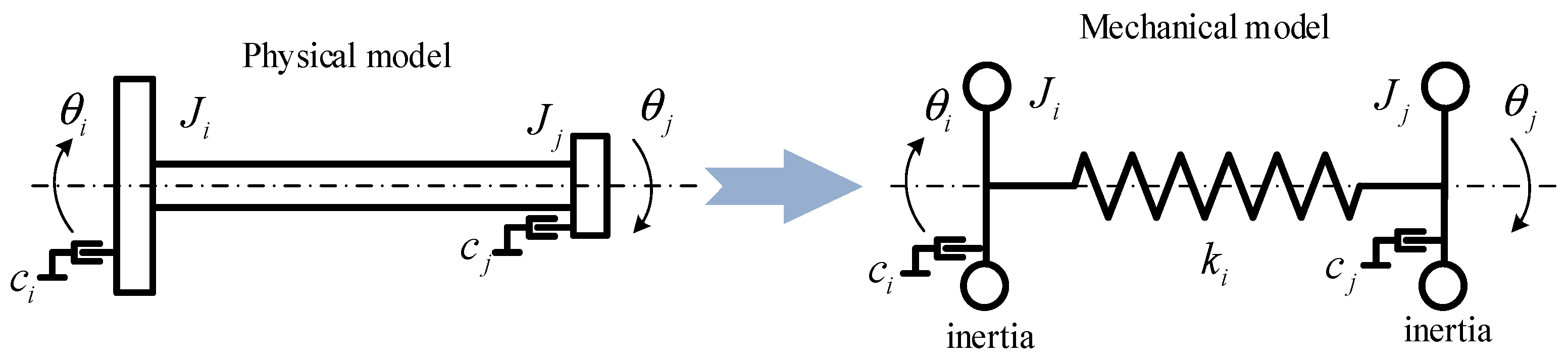
Therefore, for an
n DOF torsional vibration system comprising multiple lumped moments of inertia and torsional stiffnesses, the dynamic equation of free vibration can be derived from Newton’s second law, provided the effect of damping is neglected. The equation is typically expressed in matrix form as follows:
Equation (16) clearly illustrates that the inertial torque and the elastic restoring torque are in balance without external excitation or damping. This equation serves as the foundation for analyzing the torsional vibration characteristics of the engineering vehicle driveline. By determining the equivalent lumped moment of inertia and the equivalent lumped torsional stiffness, the foundations have been established for the partial natural frequency analysis of the engineering vehicle driveline.
The eigenvalue equation for the engineering vehicle driveline can be described accordingly as follows [
24]:
Since the moment of inertia matrix
is a positive definite matrix, the Cholesky decomposition method can be applied to decompose this matrix effectively. One can enable that
and
, so that Equation (17) can be written as:
At the same time, the normalized moment of inertia matrix
is introduced. Its eigenvalues are identical to those of the original transmission system.
can be expressed as follows:
Substitute Equation (19) into Equation (18), and Equation (20) can be obtained as follows:
where
is the identity matrix.
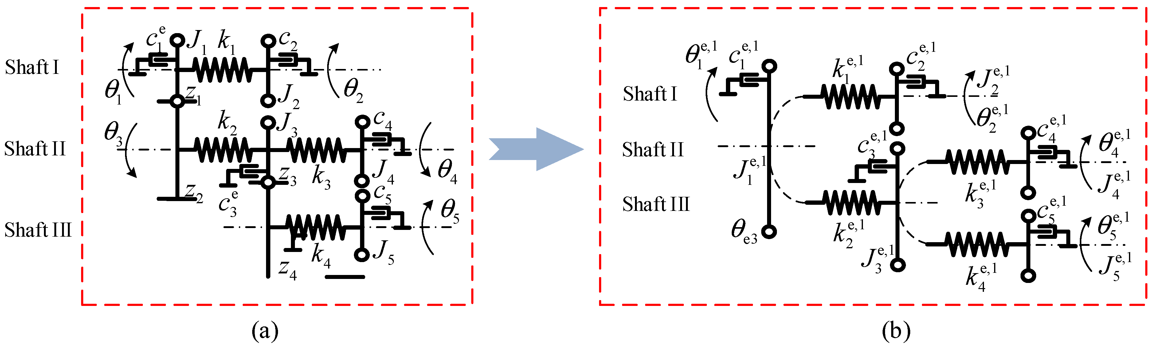
Consider an n DOF system consisting of moments of inertia connected in series with torsional springs. In this system, the structure of the moments of inertia matrix remains constant. Concretely, it is a positive-definite diagonal matrix, which means that each degree of freedom is independent of another with no coupling items. For the equivalent torsional stiffness matrix , the diagonal elements are positive, while the others are non-positive. For a torsional spring connecting -th and the -th equivalent moments of inertia. Set the equivalent torsional stiffness as . At the diagonally opposite positions in the matrix structure, .
Thus, the normalized torsional vibration system with
n DOF preserves the exact same matrix structure as the original torsional stiffness
.
can be expressed as below:
In order to assign the expected values to the natural frequencies of the corresponding orders, a real symmetric matrix
is constructed to enable the eigenvalues to be
and
, where
is the expected eigenvalue of the modified system, and
is the unmodified eigenvalue of the original system
. Accordingly,
,
,
,
and
. The moment of inertia-normalized eigenvector matrix
of Equation (17) and the normalized eigenvector matrix
of Equation (20) can be obtained, where
is the combination of
and
, and
is the combination of
and
, corresponding to
and
respectively. As the matrices
and
are capable of similar diagonalization and both are symmetric matrices, the conditions of the matrix spectral decomposition theorem are satisfied [
36]. From this, the matrix
can be expressed as:
Substituting the boundary conditions
, it can be derived as:
According to the spectral decomposition theorem, since partial natural frequencies of the original system, the corresponding normalized eigenvectors , and the expected torsional frequencies are consistent, it becomes feasible to construct a matrix that preserves the remaining eigenvalues of the original system unchanged. Therefore, there exists at least one matrix that satisfies the partial frequency assignment requirements.
However, the key distinction lies in the fact that
fails to reconstruct a physically realizable
n DOF (moment of inertia)-(torsional spring) system, even though the eigenvalues of the original matrix
and reconstructed matrix
are identical. To address this issue,
is introduced as a reconstructed moment of inertia-normalized reconstructed torsional stiffness matrix, whose eigenvalues are the same, and the physical structure can be realized, expressed as below:
where
and
are the moment of inertia and the torsional stiffness matrix of the modified torsional system, respectively.
Since the given matrix
It is a real symmetric matrix; it can be transformed into tridiagonal form by the Lanczos method to resolve the eigenvalues. An initial vector
is selected arbitrarily so that the component values lie between −1 and 1, and the reconstructed moment of inertia-normalized reconstructed torsional stiffness matrix
is derived by iterating through the Lanczos method as below:
where
.
3.2. Inverse Eigenvalue Problem and the Gradient Flow Method
Since
cannot be in the form of
or
, it requires to perform a reconstruction of
. In the literature [
37], the gradient flow method is applied for the general form of real matrix complementation, and the derivation of the real symmetric matrix complementation in the simplified form is given as follows.
Consider a real symmetric matrix
. According to the spectral theorem, a real symmetric matrix can always be diagonalized by an orthogonal transformation, which means they possess exactly the same set of eigenvalues. Therefore, there exists an orthogonal matrix
satisfying
. Let
where
and
are complementary subsets. All entries in the matrix
excluding those in
are zero, while the rest are identical to
.
Concerning the Frobenius inner product,
Thus, the orthogonal projection of
onto
can be described in an intuitive form as follows:
In this decomposition, the entries of
possesses a distinctive sparsity pattern, which means all the entries corresponding to the index subset
are identically zero. For
, the minimization equation
can be described as
As
,
can be reformulated as below:
Once it has been reformulated into the unconstrained form, the gradient of the objective function with respect to the independent variables can be determined. The gradient vector
indicates the direction and magnitude of the steepest increase in the function
, and can be expressed as below:
Post-multiplying Equation (31) by
, one obtains:
where the vector field can be explicitly derived as below.
Equation (33) describes the gradient flow associated with the objective function
evolving on an open subset constituted by an orthogonal matrix [
37]. As the flow develops, the value of
will necessarily decrease progressively along the solution curve, thereby driving the system towards a configuration that minimizes the function at the fastest rate permitted. The process of solving the ordinary differential equation system can begin with a variety of initial conditions, yet the simplest method is to initiate from the identity matrix, namely
. The initialization allows the matrix to move progressively away from the identity matrix with time, until it reaches a certain steady-state point. The original objective function at this point is the minimized value. The termination criteria for the integration of Equation (33) are selected as follows:
where
represents the Frobenius norm.
In short, gradient flow methods exhibit greater flexibility in handling structural constraints compared to traditional inverse eigenvalue methods. Inverse eigenvalue methods generally require that the modified mass-stiffness matrix maintain a specific sparsity pattern, and they struggle to handle matrices where some entries are fixed and others are free. The gradient flow method can encode fixed entries at arbitrary positions by . Furthermore, when an exact solution does not exist, the gradient flow method can converge to the minimum-squares solution (that is, the minimum of ), while the inverse eigenvalue method may fail directly or produce a matrix with no physical meaning.
3.3. Modal Damping Modification by Orthogonal Decomposition Method
According to the analysis above,
Section 3.1 and
Section 3.2 have already addressed the modification problem of the partial natural frequency assignment of the driveline. Once
and
are obtained, the lumped parameter models can be constructed accordingly, and each gear in the driveline can be reasonably designed and modified. However, the modal damping of the driveline will change accordingly due to the variation of the modified moment of inertia and torsional stiffness.
Based on the modal superposition method,
can be transformed into
where
and
is the
model coordinate.
Equation (14) becomes
and
Thus, Equations (38) and (39) can be obtained from
Section 3.1 as below:
Generally,
is not a diagonal matrix. But the damping is ignored between gears in
Section 3.2.
is a diagonal matrix.
and
are similar diagonal matrices, and Equation (38) is satisfied at the same time. The diagonal modal damping matrix
can be obtained as follows:
Then Equation (36) can be described as
Once is obtained, can be obtained from Equation (35). Then, the rotation angle of each gear can be obtained by Equation (12). From Equation (41), when the exciting frequency is around the natural frequency , the dynamic response is affected by modal damping .
From
Section 3.2, when the specific natural frequency is determined to the expected value, the modal matrix
will change. From Equation (40), the modal damping matrix
may be changed due to the change of the eigenvector after frequency modification.
If
is the required modal damping, once the modal shape matrix
is known. Based on Equation (40), we have:
The required equivalent damping matrix for the driveline system can be found
Then, from Equation (14), we can find out the required realizable damping for each bearing damping.
4. A Practical Application of Torsional Frequency Modification for Vehicle Driveline
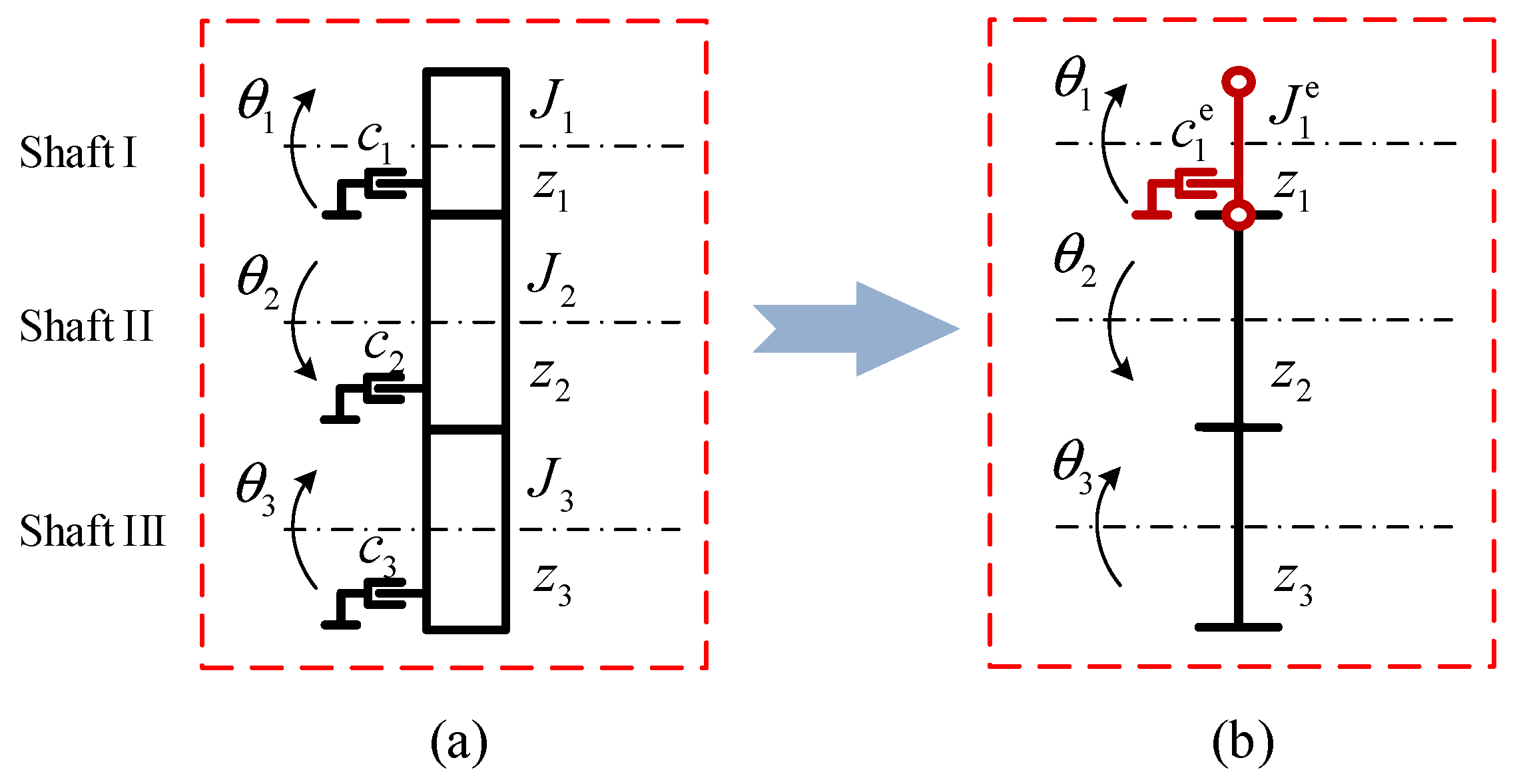
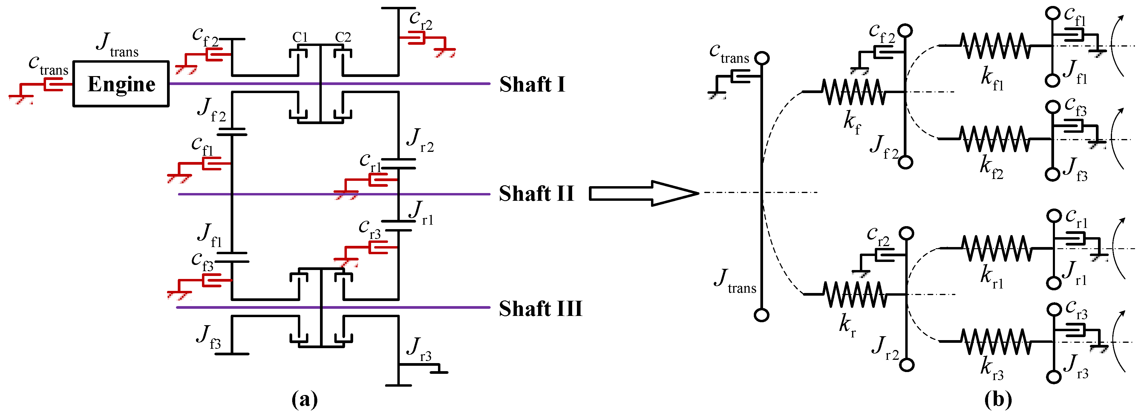
Since the structural resonance caused by torsional vibration in the vehicle driveline will directly affect the stable operation of the vehicle, it has a vital engineering significance to control the torsional vibration frequency of the vehicle driveline. In this section, a mechanical model of a certain vehicle driveline is established, as shown in
Figure 5a. In order to improve the solution efficiency, it can be equivalent to a lumped parameter model, as shown in
Figure 5b, where
and
denote the moment of inertia and the modal damping for the engine,
,
,
,
denote the moment of inertia and the modal damping corresponding to six gears, and
,
,
,
,
,
denote the torsional stiffness of the six connecting shafts, respectively. In this section, an improved PEVAPSM solution for a 7-DOF moment of (moment of inertia)-(torsional spring)-(torsional damper) is presented to demonstrate, based on the discussion above. The vehicle driveline system is analyzed and modified through the ordinary differential equation solver in MATLAB 2020B.
The matrix of the 7-DOF engineering vehicle driveline is established, whose moment of inertia and torsional stiffness matrix are expressed as below:
Originally, the equivalent lumped moments of inertia for six gears and the engine in the driveline are donated as , and the equivalent lumped torsional stiffness of shafts is donated as . Detailed parameters and values are listed below:
Based on
Table 1, the torsional natural frequencies of the driveline can be clearly determined as
. In particular, the second and third natural frequencies are of concern, which require
to be modified as the expected torsional natural frequencies
while the other frequencies remain unchanged. Accordingly, the moment of inertia-normalized torsional stiffness matrix
can be obtained that
, which can also be presented as below:
where
Consequently, the matrix
according to Equation (23) in
Section 3.1, it can be obtained as follows:
where the torsional natural frequencies of the matrix satisfy the requirements for the improved PEVAPSM method. But it differs from
, indicating that the modified torsional system is unable to change directly from
structured identically to
.
The matrix-complementary gradient flow method discussed in
Section 3.2 will currently be applied to construct the moment of inertia-normalized torsional stiffness matrix
of the modified torsional system. Some non-zero entries of
are pre-set with a value. Let some certain non-zero entries of the matrix
be preset with a value. Assume that
and
are preset values and that
referring that
= 0.01.
At this point, using the notation in
Section 3.2,
can be obtained as below:
where the blank is in
Indicate unknown entries to be determined. Set
(a
identity matrix), and start with
.
It is easy to verify that the torsional natural frequencies can be obtained as .
Now, one can reconstruct the modified inertia-torsional spring system with the same configuration structure as
, shown in
Figure 5, from
. Note that the physical parameters of the moment of inertia and the torsional springs of the modified system constitute the entries of
just like
shown in Equation (46). Take
as the static displacements of all the moments of inertia, the equivalent lumped moment of inertia constant of the original and modified structures can be obtained as below (
Table 2):
Based on
Table 2 and the derivation procedure above, the modified modal damping and the required realizable damping can be obtained as shown in
Table 3 below.
It is important to highlight the following aspects in the reconstruction process that if is chosen as an arbitrary orthogonal matrix, the gradient flow method converges to a different limit point. Consequently, from the resulting matrix above, another solution of the improved PEVAPSM problem associated with the original system. Meanwhile, if other non-zero entries of are set to be known a priori, one can also reconstruct different PEVAPSM solutions.
Since this method is an improvement on the PEVAPSM method for translational systems, it shares the same slight errors, which include errors caused by the gradient norm when computing gradient flow integrals (with a magnitude of ), as well as local truncation errors from the ode15s numerical integrator in MATLAB calculations (with a magnitude of ). These errors are acceptable. At the same time, when solving equation systems with the improved PEVAPSM method, the number of equations should be no more than the number of unknowns to ensure that the matrix is solvable.
It should be emphasized that the torsional frequency modification solution for the engineering vehicle driveline is not unique. It originates from the fundamental imbalance between mathematical constraints and design freedom. From the viewpoint of mathematics, the number of constraint equations is less than the number of unknowns, resulting in an underdetermined system. It is not a flaw of this method. On the contrary, it provides a design freedom for the driveline. This design freedom allows the physical parameters of the engineering vehicle driveline to be adjusted to satisfy different engineering requirements, thereby providing additional design freedom for other optimizations.
This modified torsional system
accurately assigns the second and third frequency to
, and keeps the remaining frequencies of
unchanged. The absolute errors of the remaining frequencies between
and
are listed in
Table 2 which indicates an excellent assignment.
Clearly, the PEVAPSM solution of this 7-DOF multiple-connected inertia-torsional spring system is not unique either. Additionally, it should be pointed out firstly that according to Equation (23) (i.e., a real symmetric matrix constructed), the spectral orders of the eigenvalues of the original system to be assigned before assignment must be in the same spectral orders of the modified system after assignment. Secondly, the first method based on the Lanczos algorithm is just applicable to the simply connected systems and is computationally effective; while the second method based on the gradient flow algorithm applies to both systems, but is computationally more expensive for large systems.