Article

Magnetic Wall-Climbing Robot with Adaptive Tracked Mobility and Anti-Overturning Modules

College of Mechanical and Electrical Engineering, Northeast Forestry University, Harbin 150040, China
*
Author to whom correspondence should be addressed.
Machines 2026, 14(4), 439; https://doi.org/10.3390/machines14040439
Submission received: 10 March 2026 / Revised: 4 April 2026 / Accepted: 13 April 2026 / Published: 15 April 2026
(This article belongs to the Section Robotics, Mechatronics and Intelligent Machines)

Abstract

Magnetic wall-climbing robots have great potential applications for the maintenance and inspection of large steel structures. However, they are susceptible to overturning when climbing over obstacles on vertical walls, primarily due to localized failures in the adhesion and shifts in the center of gravity. To address this issue, this paper presents an improved robot design featuring a passive adaptive tracked mobility module and a link-spring anti-overturning module. The adaptive tracked mobility module, incorporating spring tensioning mechanisms and belt press wheels, enables dynamic conformity to uneven walls and maintains stable magnetic adhesion. The link-spring anti-overturning module converts the front-end lift during obstacle crossing into an anti-overturning moment applied to the rear end of the robot. Notably, there is no need for additional drivers or control units. The structural design and three-dimensional modeling of the robot are carried out. Its working principle is analyzed, and parametric modeling and simulation analysis are performed. A physical prototype is developed and obstacle-crossing experiments are conducted on a vertical wall. The results demonstrate that the adaptive tracked mobility module and the anti-overturning module can successfully assist the robot in climbing over an obstacle with a maximum height of 23 mm, and the robot exhibits excellent stability while climbing over continuous obstacles and moving on uneven vertical walls.

1. Introduction

In the automated maintenance, inspection, and repair operations of large steel structures (e.g., large storage tanks and wind power towers), wall-climbing robots have become an important research direction in the fields of intelligent manufacturing and special robots because they are capable of replacing humans in performing continuous tasks in high-risk, high-load and extreme environments [1,2]. At present, the primary technologies for achieving stable robotic climbing include negative pressure adhesion [3,4,5], mechanical adhesion [6,7], electrostatic adhesion [8,9,10], elastomer adhesion [11,12,13] and magnetic adhesion [14,15,16,17,18]. Among these technologies, magnetic adhesion, especially the adhesion method based on permanent magnets, demonstrates outstanding performance in steel structures due to its comprehensive advantages, including strong adhesion, adaptability to various steel surfaces, relatively simple structure and high reliability. Permanent magnetic adhesion tracked robots not only possess the above-mentioned advantages but also offer excellent obstacle-crossing ability, stable motion performance, and high load capacity. Therefore, they are widely regarded as one of the most promising technical solutions for automated inspection, cleaning, flaw detection, spraying and other operations on the surface of large steel structures [19,20,21,22].
At present, the climbing functions of permanent magnetic adhesion tracked robots on vertical walls have been achieved. However, such robots still face some challenges in practical applications; for instance, how to adapt to complex wall conditions characterized by uneven features such as welds, rivets or other obstacles [23]. When the front end of the robot climbs over the obstacle, the overall posture of the robot body changes and the center of gravity moves away from the wall, generating an increasing overturning moment. Meanwhile, the front magnetic unit loses contact with the wall because of the presence of the obstacle, leading to a significant loss of adhesion. These changes readily induce a rearward overturning of the robot.
To enhance the obstacle-crossing ability and dynamic stability of robots, scholars have carried out numerous studies. Gao et al. proposed a dual-module magnetic adhesion robot system for non-destructive testing [24]. This design links two independent climbing modules through an anti-overturning mechanism with an internal compression spring. Its elastic elements can automatically adjust the relative posture between the modules when the terrain changes, thereby effectively suppressing the sudden lifting and adhesion loss of the front-end track at the moment of contact with obstacles. T. Seo and M. Sitti have expanded the classic tank-type robot configuration [25]. They couple two mobile modules through a rigid connection mechanism, significantly enhancing the overall reliability of the system when traveling on discontinuous walls. The design innovatively introduced an actively controlled tail support structure, which can adjust the force application point in real time according to the robot’s pitch posture, thereby actively offsetting the overturning moment caused by obstacle crossing and further optimizing the dynamic stability. Li broke through the limitations of traditional centralized load and innovatively proposed a distributed load transfer mechanism [26]. This design evenly distributes the self-weight of the robot body and the working load to all independent magnetic adhesion units through precision guide rails and T-shaped connecting rod systems, significantly reducing the lateral flipping load borne by each adhesion unit. Wang proposed an anti-overturning mechanism [27]. He designed a 3RIP hybrid passive mechanism and optimized its parameters through the particle swarm optimization algorithm. The experiments verified that the obstacle crossing height of the robot was improved. Although significant progress has been made in existing research, there are some limitations. These include insufficient obstacle-crossing capability and limited self-adaptive performance of the track mechanism. Traditional rigid tracks are difficult to maintain continuous and tight adhesion on uneven walls, resulting in an increased air gap between the magnet and the wall. This results in fluctuations and attenuation of the adhesion and makes the system susceptible to overall overturning during obstacle crossing. Many anti-overturning schemes rely on multi-module active control or complex drive mechanisms, which inevitably increases the robot’s weight, control complexity and energy consumption.
To overcome the above shortcomings, this paper proposes an improved magnetic wall-climbing robot. The robot employs two tracks equipped with magnetic adhesion units and an integrated adaptive tracked mobility module. Adaptive tracked mobility module enables the tracks to dynamically adapt to the uneven features of the wall and maintain a constant magnetic adhesion. At the same time, a link-spring anti-overturning module is equipped at the rear of the robot, which automatically and rapidly converts the lifting movement at the front end of the robot into an anti-overturning moment acting on the rear end of the robot body. This robot does not require additional drivers or control units. It can significantly enhance the robot’s motion stability and obstacle-crossing safety on the uneven walls of vertical steel structures.

2. Design of the Wall-Climbing Robot

2.1. Overall Structure

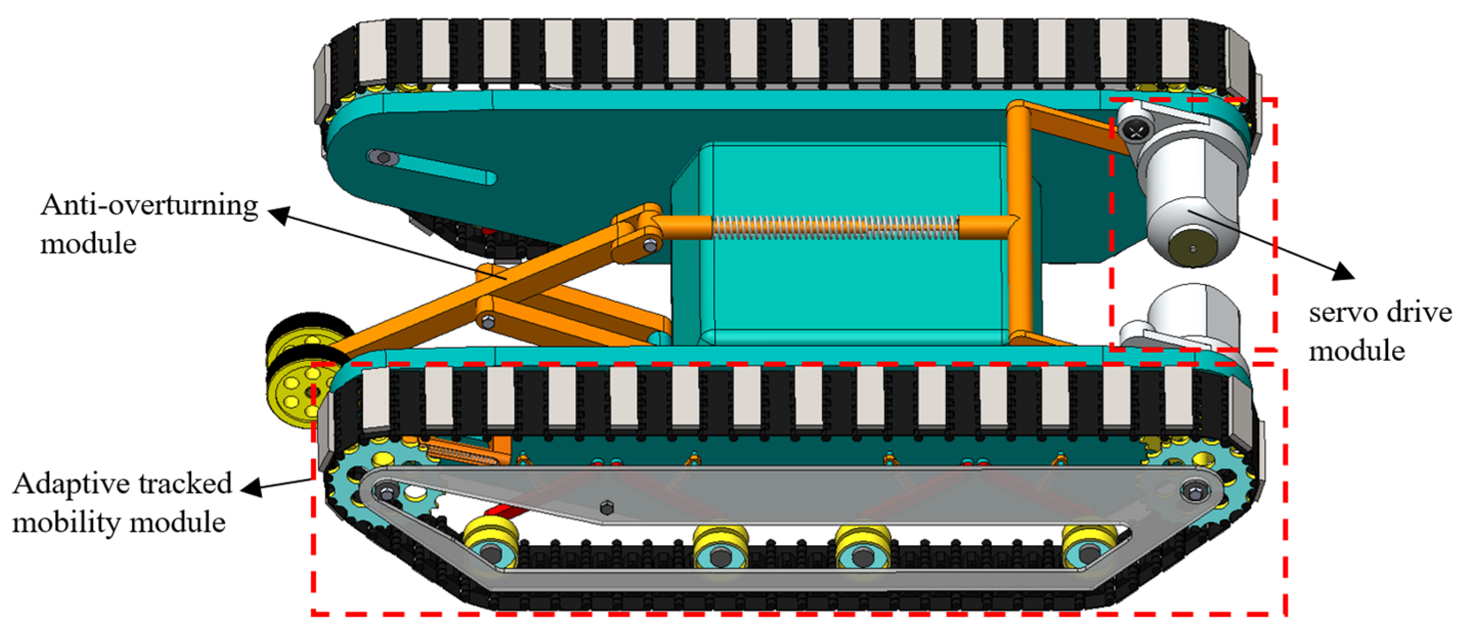
This design aims to achieve stable and reliable adhesion and movement of wall-climbing robots on vertical walls. The wall-climbing robot is composed of an adaptive tracked mobility module, an anti-overturning module and a servo drive module, as is shown in Figure 1. As the power source, the servo drive module provides precise power to the tracks on both sides, enabling forward/backward movement and differential steering. The adaptive tracked mobility module integrates permanent magnetic adhesion units on its tracks, which generate a strong and uniform adhesion and provide a basic guarantee for the robot to overcome gravity. The anti-overturning module functions as a crucial stability subsystem by providing an anti-overturning moment during obstacle-crossing. Additionally, it effectively increases the normal pressure of the tracks against the wall surface, thereby preventing the robot from overturning due to localized adhesion failure. Collectively, the three modules work in concert to ensure the robot’s reliability and stability when climbing over obstacles on vertical walls.

2.2. Adaptive Tracked Mobility Module

2.2.1. Structure of Adaptive Tracked Mobility Module

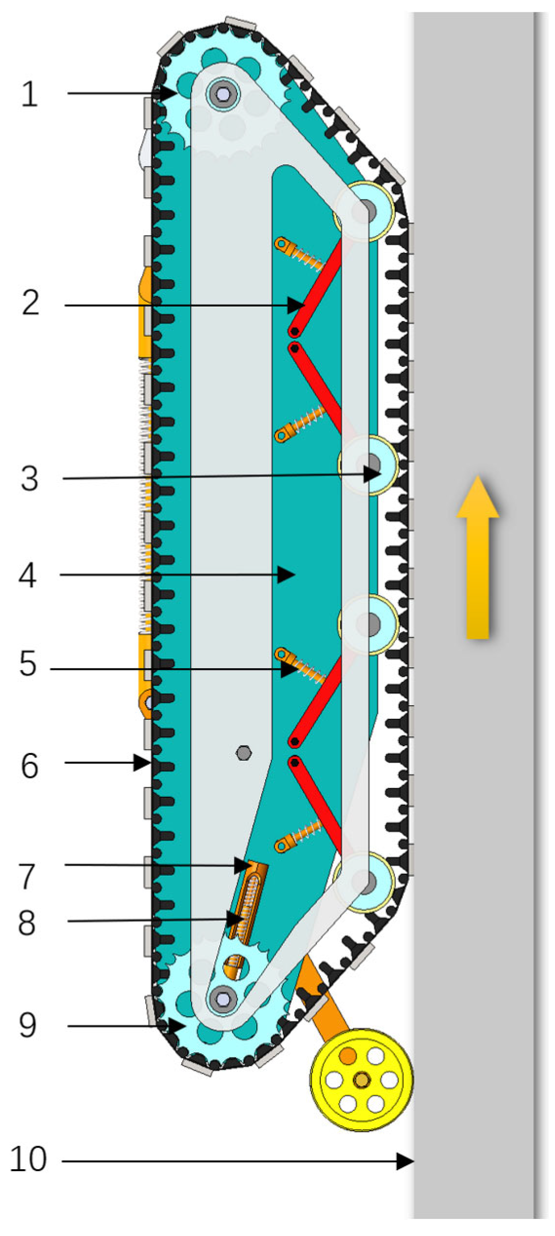
The adaptive tracked mobility module is the key component that enables the robot to achieve reliable adhesion and flexible movement on vertical walls. It ensures that the robot can maintain a stable adhesion on complex surfaces and has the ability to passively adapt to terrain changes. This module adopts an integrated configuration that combines drive, transmission, adhesion and adaptive tensioning. It mainly consists of the driving wheels, driven wheels, belt press wheels, links, spring rods, pre-compressed spring tensioning mechanisms, tracks equipped with permanent magnetic adhesion units and the frame that serves as the main supporting and connecting structure, as is shown in Figure 2.
The driving wheel is located at the front end of the module and is connected to the servo motors to form the drive unit. The entire drive unit is fixed on the frame. The driven wheel serves as the dynamic tensioning wheel of the system. Its axle ends are embedded in the linear grooves on the frame, allowing the driven wheels to slide freely back and forth along the grooves and forming the mechanical basis for its adaptive motion. A pre-compressed spring serves as the tensioning element, with one end acting on the bearing housing of the driven wheels and the other end fixing on the frame. The pre-compressed spring tensioning mechanism can continuously provide tension force for the driven wheels, ensuring that the track remains tensioned at all conditions. The belt press wheels are the key components to achieve dynamic adhesion between the tracks and the uneven surface. There are four belt press wheels on each track. Each belt press wheel is hinged at one end of a link, and the other end of the link is hinged to the frame. At the same time, the middle part of the link is hinged at a spring rod, and the other end of the spring rod is hinged to the frame. The four links are arranged in a crosswise configuration.
When the robot moves on a flat vertical wall, the weight G generates an overturning moment about the rear contact point of the track. The moment arm of the overturning moment is the vertical distance δ between the robot’s center of gravity and the wall. In the adaptive tracked mobility module, n permanent magnetic adhesion units are installed on each track at equal intervals, and n′ units remain in contact with the wall. Each unit provides an adhesion of F0 which can generate an anti-overturning moment. The moment arm for each permanent magnetic adhesion unit is the distance Li from its center to the rear contact point of the track. It is assumed that the distance between the front and rear ends of the track is d.
Based on the above analysis, to maintain stable movement on a flat vertical wall, the anti-overturning moment generated by the permanent magnetic adhesion units must be greater than the overturning moment caused by the robot’s weight:
i = 1 n F 0 L i = F 0 d + d d n + d 2 d n + + d n > G δ
When the robot encounters obstacles on the wall, the vertical distance δ between the robot’s center of gravity and the wall increases, which introduces a risk of overturning. A safety factor S is therefore introduced. Considering most practical working conditions, in this paper, S is set to 1.4. To ensure the robot can stably climb over obstacles, the anti-overturning moment generated by the permanent magnetic adhesion units must be greater than 1.4 G δ.

2.2.2. Working Principle of the Adaptive Tracked Mobility Module

The adaptive tracked mobility module achieves the coordinated operation of adhesion, movement and passive adaptation through mechanical coupling.
The passive adaptation is achieved through the combined efforts of the belt press wheels and the spring tensioning mechanism. When the robot moves on flat vertical wall, the pre-compression force of the pre-compressed spring on the driven wheels keeps the track in tensioned state. Meanwhile, the belt press wheels press the track against the wall under the pressure of the spring rod, ensuring the minimization of the air gap between the magnet and the wall, and the maximization of the adhesion. When the robot encounters a protruding surface or an obstacle, the passive adaptive mechanism is triggered.
(1) The belt press wheels respond first. The track is lifted and the local force is transferred to the belt press wheels, compressing the spring rod. This mechanism can adapt to the changes in wall surface and allow the track to undergo smooth bending deformation, thereby increasing the contact area between the track and the wall surface, which can prevent a sudden drop in adhesion due to insufficient local contact area.
(2) The pre-compressed spring tensioning mechanism of driven wheel operates synchronously. The effective envelope circumference requirement of the tracks increases due to being lifted by the protruding surface. This change is transmitted to the driven wheels through the tracks and exerts a certain pressure on the0m, causing the spring to compress and driving the driven wheels to move along the linear grooves. This motion releases additional track length and can compensate for the increased length requirement caused by the wall surface protrusion. As a result, the tracks achieve better surface conformity, which significantly increases the effective contact area between the track and the wall and ensures the stability of the magnetic adhesion.

2.3. Anti-Overturning Module

2.3.1. Structure of the Anti-Overturning Module

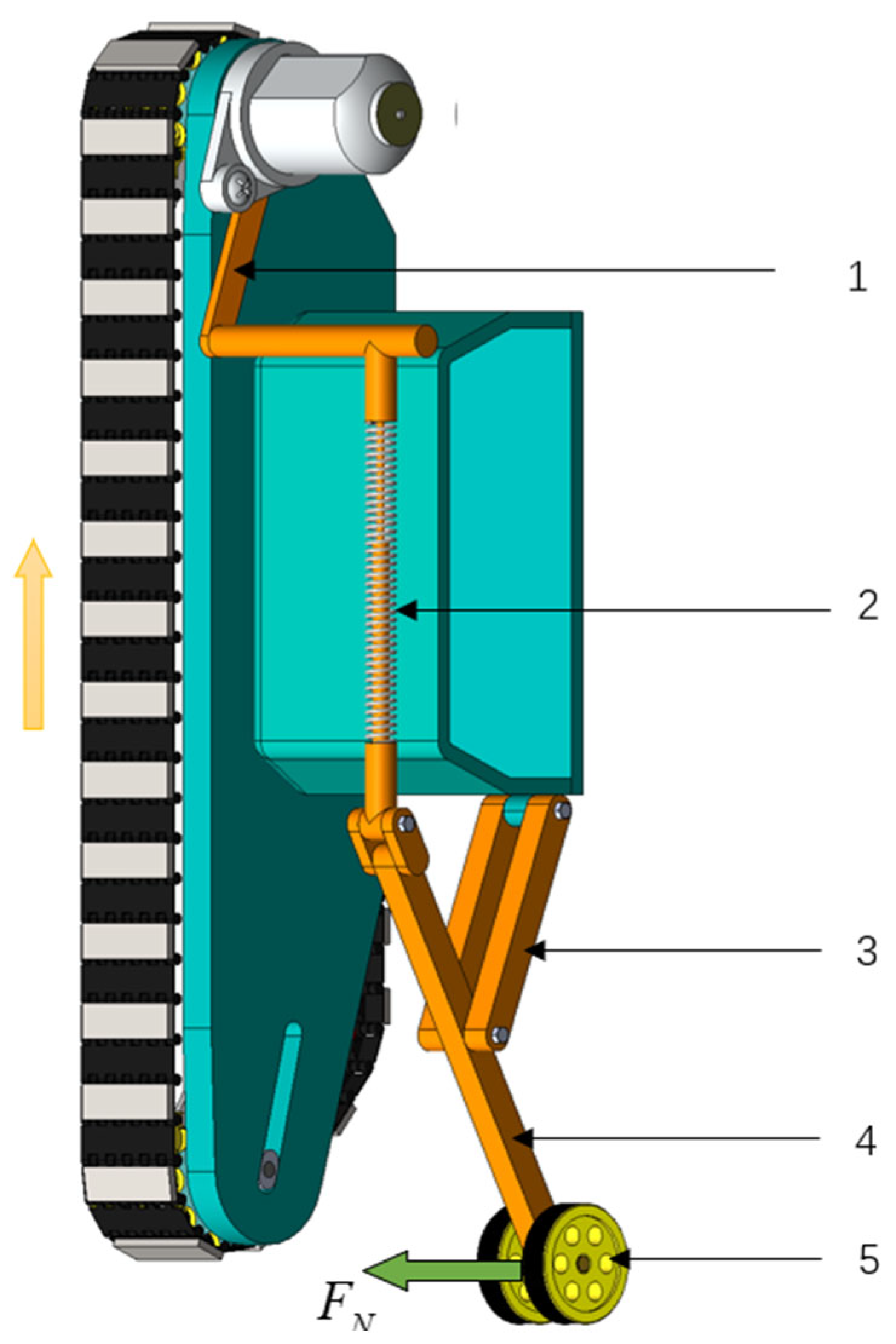
When the robot climbs over an obstacle, its overall posture will be changed. The front end of the robot is lifted, causing a shift in the center of gravity of the robot. This change significantly increases the overturning moment about the contact point of the rear track. To compensate for this dynamic overturning moment, it is necessary to introduce an anti-overturning moment that can be adaptively generated in the opposite direction. Based on this principle, a link-spring anti-overturning module is introduced for the robot, which can convert the posture changes at the front end of the robot into an anti-overturning moment at the rear end and effectively maintain the dynamic stability of the robot during obstacle crossing, as is shown in Figure 3.
The core of the anti-overturning module is a motion and force transmission system composed of multiple links. It includes a support swing rod, link P, link Q and a spring rod. One end of the support swing rod is equipped with a magnetic roller. The middle part of the support swing rod is hinged to the robot body via the link Q, which allows the support swing rod to rotate within a certain angle range in the vertical plane. The link P is located at the front end of the anti-overturning module, forming a front-mounted supporting point. It is connected to the support swing rod via a spring rod. The spring rod is in a pre-compressed state during initial installation. The link P and spring rod can transmit the pitch of the robot body to the support swing rod and the magnetic roller.

2.3.2. Working Principle of the Anti-Overturning Module

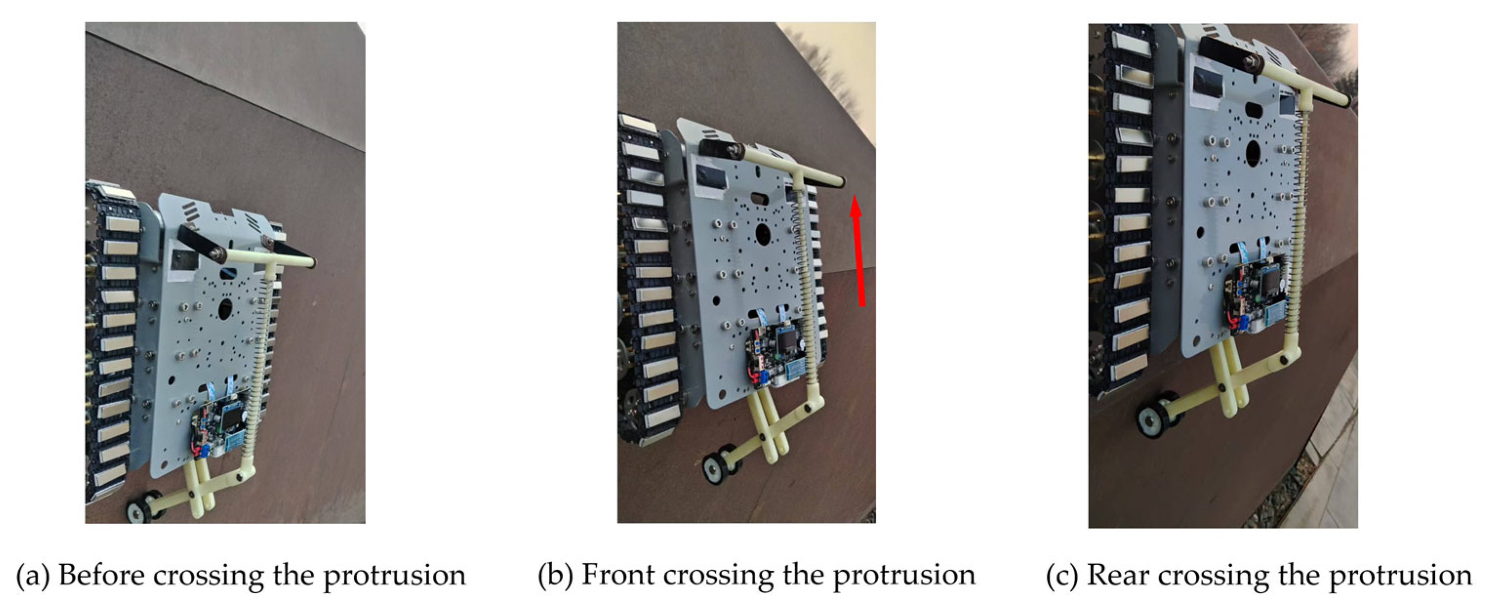
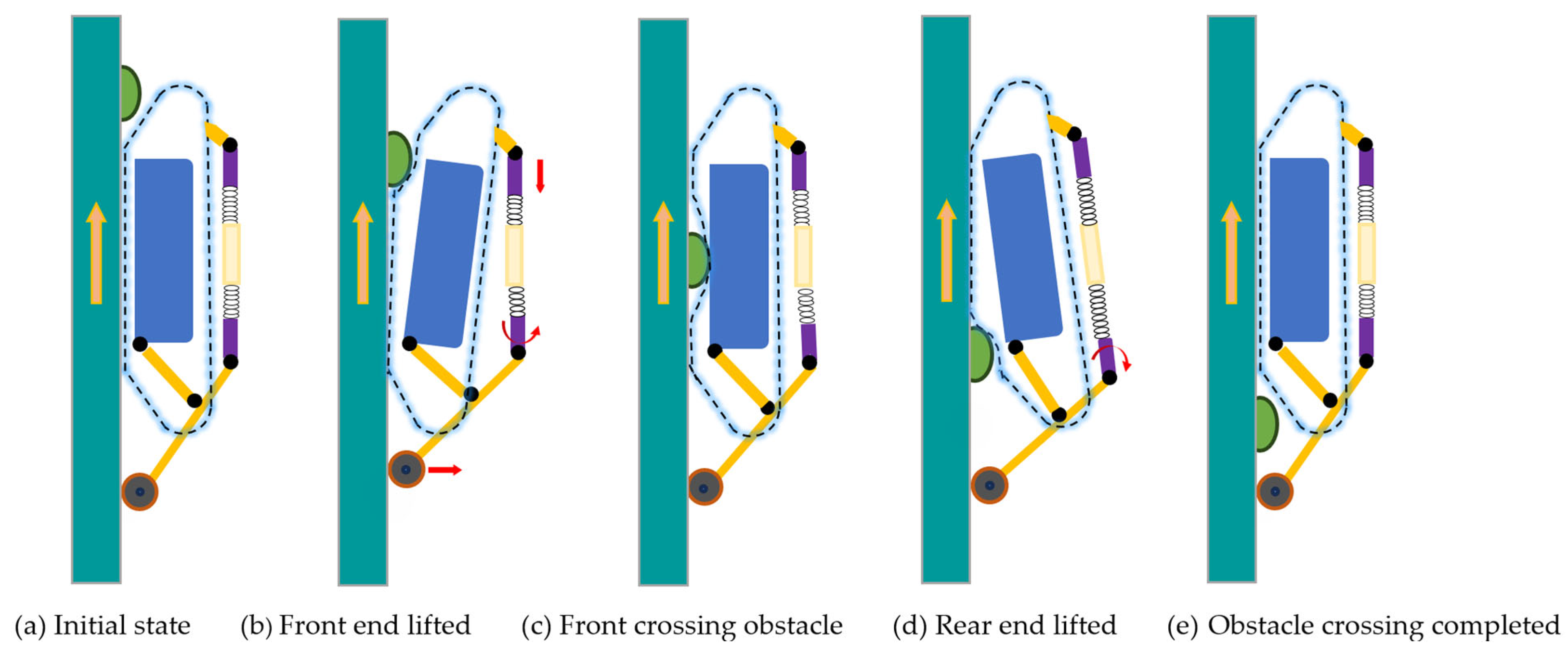
When the robot is climbing over an obstacle as shown in Figure 4, the front end of the robot will be lifted (Figure 4b). The variations in the robot’s pitch angle apply a pressure force on the link P, forcing the spring rod to compress. At the same time, the elastic force provided by the spring rod acts on the support swing rod, which increases the support force FN on the magnetic roller installed at the end of the support swing rod from the wall. The moment direction generated by FN on the robot is opposite to the overturning moment, thereby providing an anti-overturning moment. After the front end of the robot climbs over the obstacle (Figure 4c), the compressed spring rod releases its stored elastic potential energy, thereby reducing the support force FN on the magnetic roller. As the obstacle crossing process continues (Figure 4d), the rear end of the robot will be lifted. Although the support force FN continues to reduce, the magnetic roller maintains wall contact due to the pre-compression of the spring rod. After the robot completely climbs over the obstacle (Figure 4e), the anti-overturning module returns to its initial state. As illustrated in Figure 4, during the obstacle-crossing process, the anti-overturning module continuously monitors posture changes in the robot and correspondingly adjusts the support force FN to regulate the anti-overturning moment, which forms a negative feedback mechanism to ensure the stability of the robot.

3. Parameter Modeling of the Modules

3.1. Parametric Modeling of Robot Obstacle-Crossing on a Flat Wall

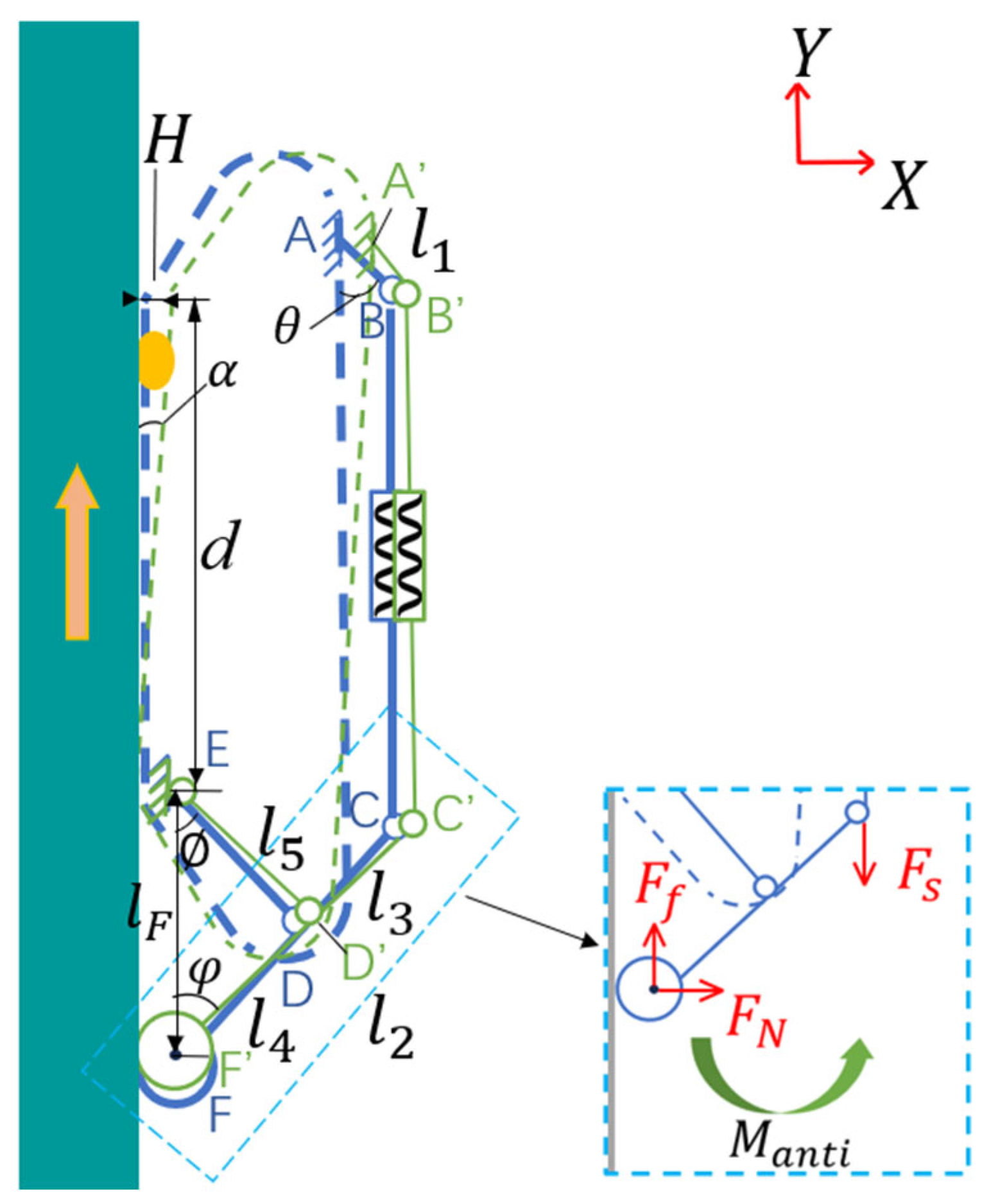
The design objective of anti-overturning module is to ensure that it can output sufficient anti-overturning moment and effectively mitigate the overall instability risk when the robot is in the most dangerous situation. It can be easily seen from Figure 4 that the most dangerous situation occurs when the robot is in the state shown in Figure 4b during obstacle crossing. Taking the contact point E between the rear track of the robot and the wall as the origin, a rectangular coordinate system is established. The direction perpendicular to the wall surface is the X-axis direction, and the direction along the wall surface is the Y-axis, as is shown in Figure 5. For parametric description, the link P is defined as the link AB; the spring rod is defined as the spring rod BC; the support swing rod is defined as the link CF, and the link Q is defined as the link DE.
Assuming the height of the obstacle is H, the dip angle α of the robot body is defined as
α = arcsin H d
In the initial state of the robot, the initial coordinates of point A are (xA, yA). When the robot is climbing over an obstacle with a height of H, point A moves to point A′ and the coordinates of point A′ are given by
x A = x A cos α y A sin α y A = x A sin α y A cos α
The initial coordinates of point B are determined by the initial coordinates of point A and the link AB. The initial coordinates of point B are given by
x B = x A + l 1 cos θ y B = y A + l 1 sin θ
When the robot body is climbing over an obstacle with a height of H, point B moves to point B′ and the coordinates of point B′ can be expressed as
x B = x B cos α y B sin α y B = x B sin α + y B cos α
When the robot starts to climb over the obstacle, the spring rod will rotate a certain angle counterclockwise. This rotation changes the direction of the elastic force applied by the spring rod to the supporting swing rod. Consequently, the length of the elastic force arm acting on the supporting swing rod increases. the magnetic roller receives an increased support force from the wall. By conducting a force analysis on the supporting swing rod, it can be inferred from the force balance condition that the support force acting on the magnetic roller increases. It is assumed that the elastic coefficient of the spring rod is K, and the initial pre-compression force is Fs0. when the robot is in the state shown in Figure 4b, the elastic force Fs provided by the spring rod can be expressed as
F s = F s 0 + K y A + l 1 sin θ y B cos α x B sin α
In Figure 5, the dip angle φ of the link CF can be calculated from the length of the link CF and the distance between point C and the wall:
φ = arcsin x B cos α y B sin α l 2
The frictional force Ff between the magnetic roller and the wall is
F f = μ F N
where μ is the coefficient of friction.
Taking point D as the moment center, the moment balance equation of the link CF can be expressed as
M D = 0 F N l 4 sin 90 ° φ = F s l 3 sin φ + F f l 4 sin φ
From Equation (9), the relationship between the supporting force FN and H can be expressed as
F N = l 3 l 4 F s H sin φ H cos φ H μ sin φ H
where
F s H = F s 0 + k y B + x B H d y B 1 H 2 d 2
sin φ H = x B 1 H 2 d 2 y B H d l 2
cos φ H = 1 sin 2 φ H
Taking the point E as the moment center, the anti-overturning moment Manti provided by the anti-overturning module is
M a n t i = F N l F
where lF is the lever arm length of the support force FN.
Equation (7) and the parameters l4, l5 can be used to calculate the lF:
l 5 sin φ = l 4 sin ϕ
l F = l 5 sin φ sin 180 ϕ φ
where ϕ is the angle between the link DE and the wall.
In the adaptive tracked mobility module, 30 permanent magnetic adhesion units are mounted on each track at equal intervals, and 12 units remain in contact with the wall during the robot movement. Each unit provides an adhesion of 13 N. Considering the force characteristics of the magnetic wall-climbing robot during obstacle crossing, and based on previous studies on permanent magnetic adhesion force calculation [28,29], the adhesion Fi(H) of a single permanent magnetic adhesion unit can be expressed as
F i H = 13 e K g g i
where Kg is the air gap coefficient, and gi is the air gap between the i-th permanent magnetic adhesion unit and the wall.
When the robot climbs over an obstacle on the wall, the air gaps between the permanent magnetic adhesion units and the wall are varying. During obstacle crossing, the front units detach from the wall first, with the largest air gap; the rear units stay in contact with the wall, with an air gap close to zero. Considering the tensioning effect of belt press wheels on the track during obstacle crossing, the air gaps near the obstacle approximately follow an exponential distribution from front to rear. To describe the air gap distribution, the air gap gi of the i-th permanent magnetic adhesion unit is established as follows:
g i = H 1 e μ 12 i 11 2
where μ is the coefficient related to the adaptive tracked mobility module.
Thus, the adhesion Fi(H) of the i-th permanent magnetic adhesion unit on the track is
F i H = 13 exp K g H 1 e μ 12 i 11 2
Based on Section 2.2.1, the anti-overturning moment M a n t i provided by two adaptive tracked mobility modules during obstacle crossing is
M anti = 2 i = 1 12 F i H L i = 2 i = 1 12 F i H d + d d 12 + d 2 d 12 + + d 12
To ensure that the robot can safely climb over the obstacle, the total anti-overturning moment and the overturning moment M o v must satisfy the following condition:
M anti + M a n t i > M o v = G d 2 sin α + δ
The designed parameters of the anti-overturning module are shown in Table 1.
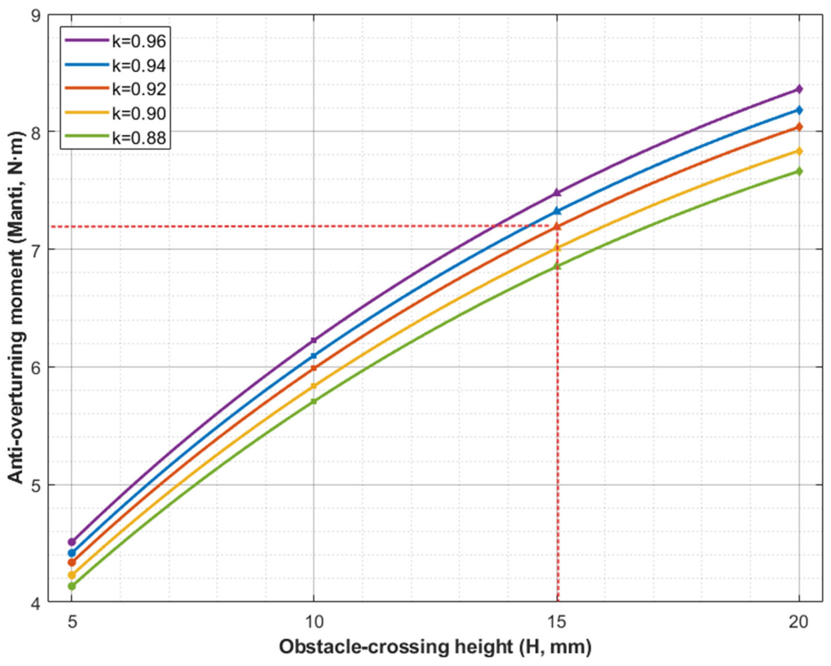
In practical engineering applications, the wall surface obstacles (e.g., weld seams) typically do not exceed 15 mm in height. According to Equations (10)–(16) and the relevant parameters listed in Table 1, the support force FN acting on the magnetic roller is 59.42 N and the corresponding anti-overturning moment Manti is 7.187 N·m when the robot climbs over an obstacle with a height of 15 mm.

3.2. Parametric Modeling of Robot Motion on an Uneven Wall

When the robot moves on uneven wall such as protrusions, depressions, or curved surfaces, characteristic angles including the protrusion angle, depression angle, and natural dip angle all affect the wall-climbing performance. Therefore, it is necessary to model the motion of the robot on the uneven wall surfaces. In this paper, an uneven wall with a β obtuse triangular protrusion is taken as an example, and the modeling principle for other uneven walls with characteristic angles is similar.
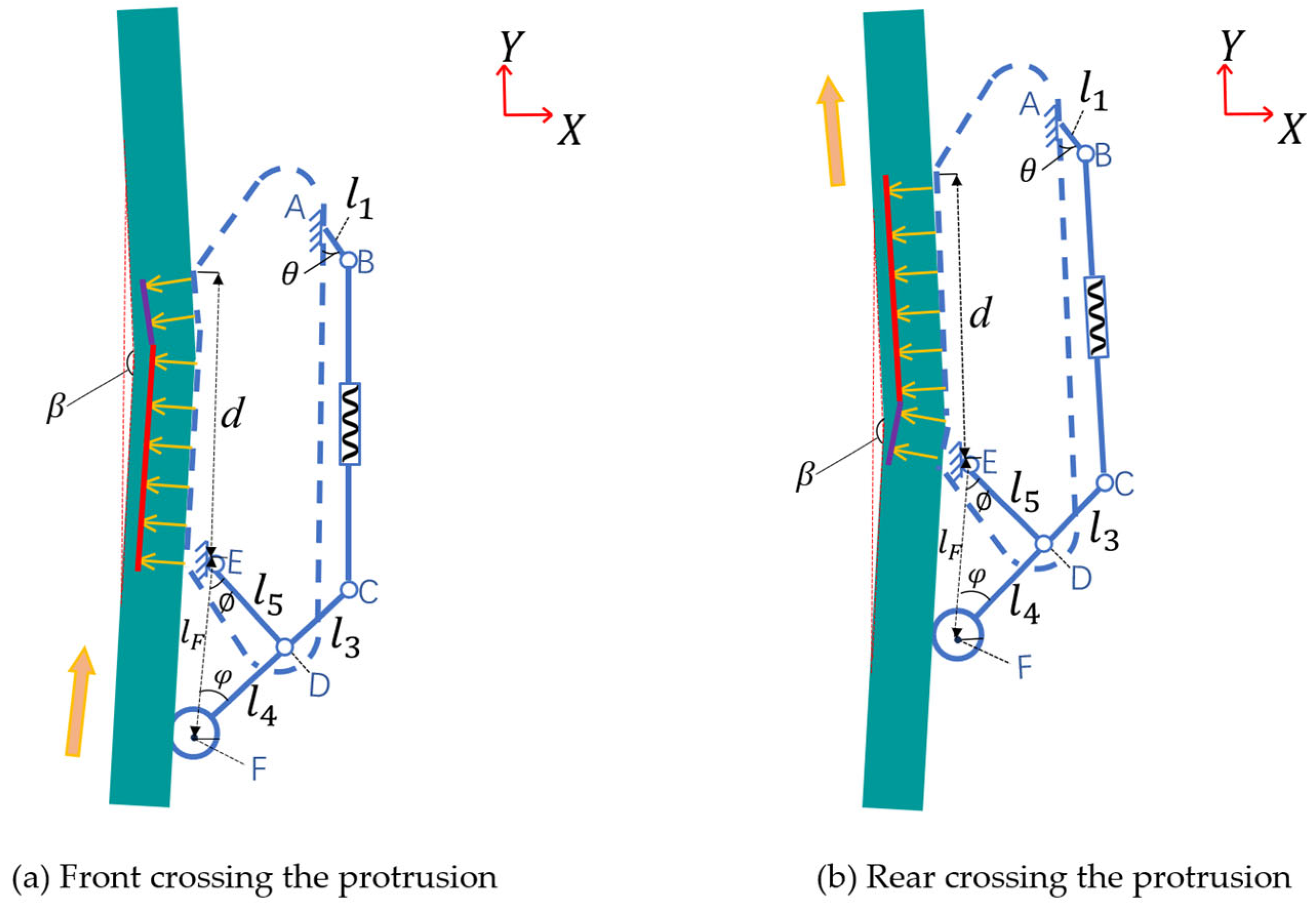
When the robot moves on an uneven wall with a β obtuse triangular protrusion, as shown in Figure 6a, most of the units at the rear end of the adaptive tracked mobility module remain in contact with the wall. Due to the tensioning characteristic of the belt press wheel, the moment arm of the adhesion between the front j units and the wall changes. Under this condition, the anti-overturning moment M a n t i , u n provided by two adaptive tracked mobility modules is
M a n t i , u n = 2 i = 1 j F i H L i cos π β 2 + i = j + 1 12 F i H L i
For the anti-overturning moment provided by the anti-overturning module and the overturning moment generated by the robot’s gravity, the calculation principles are the same as those when the robot is on a flat wall. It is only necessary to replace the robot’s dip angle caused by obstacles with the characteristic angle of the uneven wall. When the robot moves to the position shown in Figure 6b, the shift in center of gravity becomes smaller, and the overturning moment decreases significantly. The anti-overturning moment provided by the adaptive tracked mobility module can ensure safe motion.

4. Simulation Analysis of Anti-Overturning Module

4.1. Influence of Spring Elastic Coefficient K on the Supporting Force FN

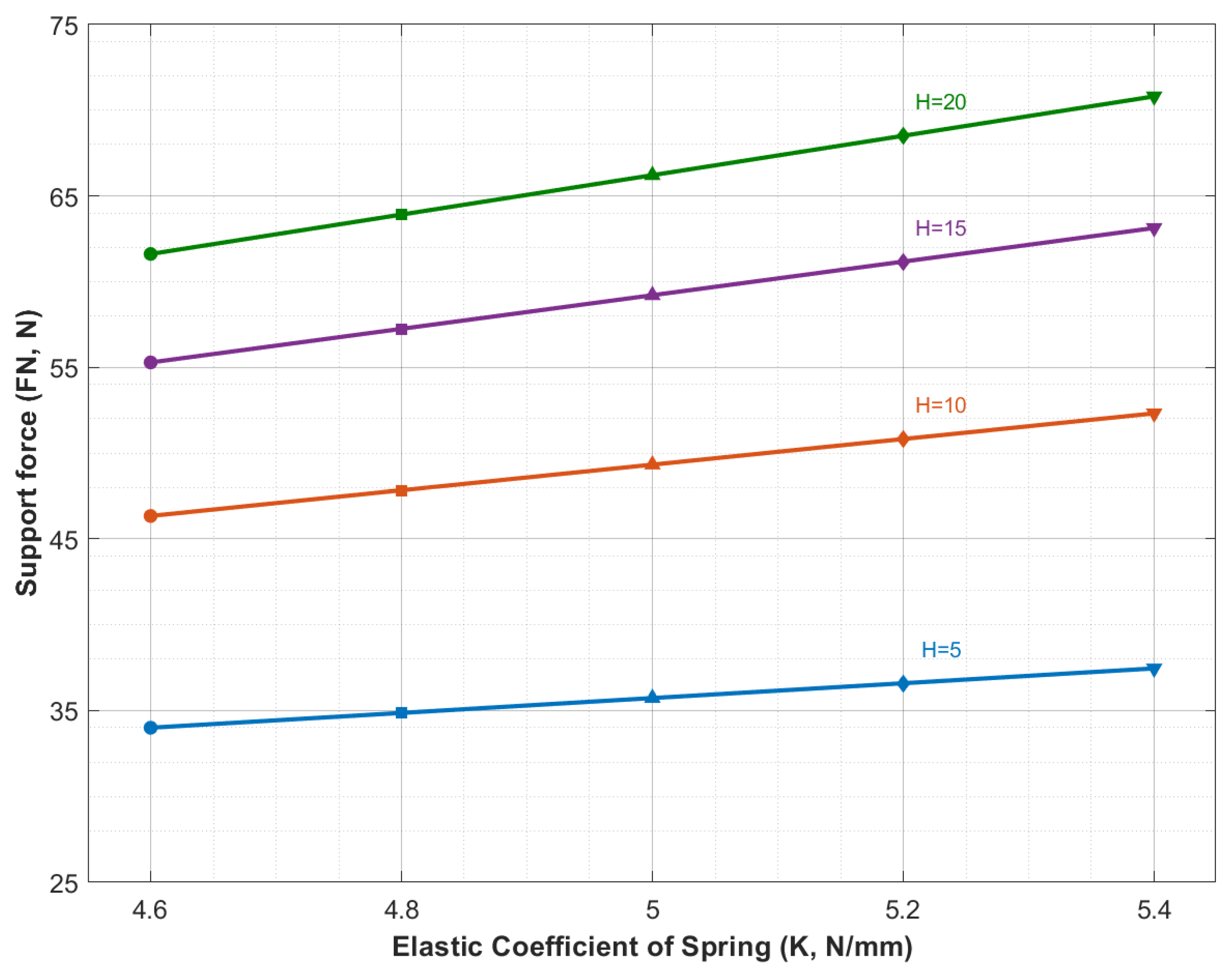
To determine the influence of the spring elastic coefficient K on the support force FN acting on the magnetic roller of the anti-overturning module, a simulation is carried out based on the mechanical model of the anti-overturning module established in Section 3. The simulation focuses on the most critical working condition (corresponding to the state in Figure 4b) during the robot’s obstacle crossing process, investigating the influence of the spring elastic coefficient K on the supporting force FN at different obstacle heights H. The relationship curve between the support force FN and spring elastic coefficient K is shown in Figure 7.
The following conclusions can be drawn from Figure 7:
(1) For a given obstacle height, the support force FN exhibits an approximately linear increase trend with the increase in the spring elastic coefficient K. This indicates that the spring elastic coefficient K has a significant positive effect on FN. A larger K results in a greater the elastic force generated by the spring compression, which in turn exerts stronger pressure on the magnetic roller through the link mechanism.
(2) The influence of K on FN becomes more pronounced as H increases. Under H = 5 mm, FN increases by 1.73 N when K increases from 4.8 N/mm to 5.2 N/mm. In contrast, for a high obstacle (H = 20 mm), the increase in FN is 4.60 N over the same range of K. This demonstrates that in the high-obstacle conditions, the adjustment of the spring elastic coefficient has a more significant effect on improving the anti-overturning performance, which is consistent with the requirement for a larger anti-overturning moment in such conditions.

4.2. Analysis of Anti-Overturning Performance

To evaluate the anti-overturning performance of the anti-overturning module, a simulation experiment is conducted to analyze the anti-overturning moment Manti. The magnitude of moment Manti is closely related to the geometric parameters of the link mechanism. As indicated by Equation (10), it depends significantly on the length ratio k (k = l4/l3) between the link CD and link DF. Based on Equations (10)–(16), the relationship between the anti-overturning moment Manti and the obstacle height H under different k values is investigated. The results are shown in Figure 8.
As shown in Figure 8, for a given obstacle height, a larger value k results in a greater anti-overturning moment Manti generated by the module. This indicates that increasing k can effectively enhance the anti-overturning capacity of the module. However, the value of k is subject to practical constraints. On the one hand, an excessively large k increases the length of the support swing rod, which is prone to motion interference with obstacles during obstacle-crossing. On the other hand, an extended length of the support swing rod reduces the structural strength of the mechanism, while increasing the weight and spatial occupation of the module. Therefore, to fully utilize the performance of the anti-overturning module and meet most operational requirements of the robot, k is set to 0.92 in this paper. Furthermore, as shown in Figure 8, when k remains constant, the anti-overturning moment Manti increases with the increase in the obstacle height H, which validates the effectiveness of the anti-overturning module.

5. Prototype Development and Experimental Verification

5.1. Prototype and Experimental Setup

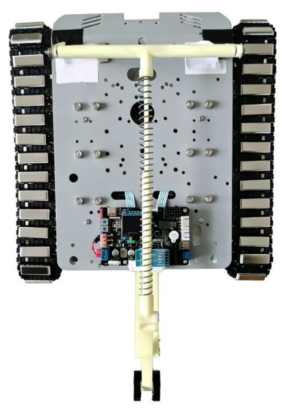
The prototype of the wall-climbing robot used in the experiment is shown in Figure 9. Its overall dimensions are 360 mm × 312 mm × 142 mm, and the total mass is 6.4 kg. The main structure of the wall-climbing robot is fabricated from aluminum alloy and stainless steel, while the two tracks are made of polyurethane. Each track is equipped with 30 permanent magnetic adhesion units and each permanent magnetic adhesion unit can provide an adhesion of 13 N. The robot is driven by two servo motors and controlled by a system with an STM32 microcontroller.

5.2. Experiments

5.2.1. Single Obstacle-Crossing Experiment

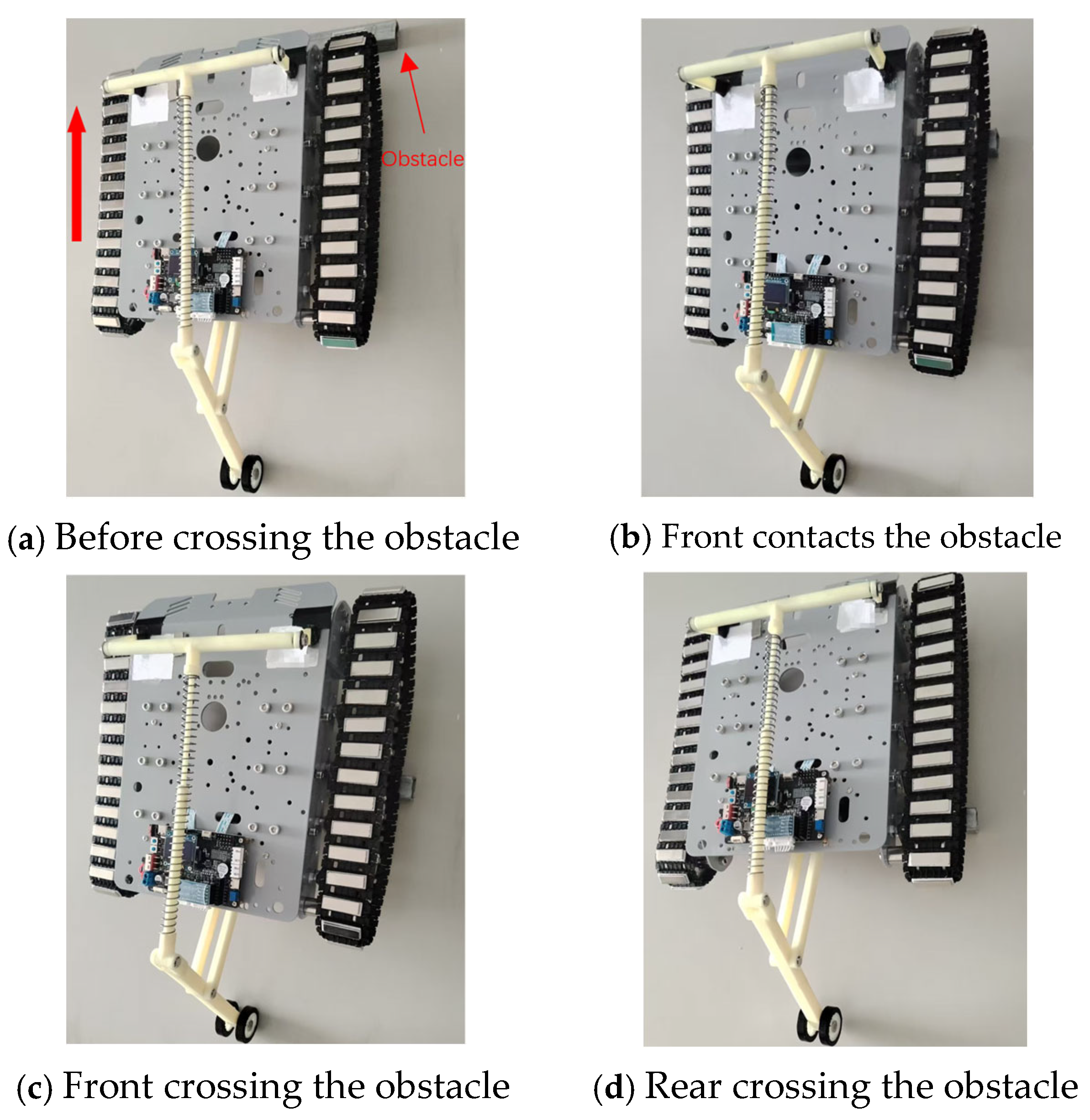
Figure 10 shows the process of the robot successfully climbing over an obstacle with a height of 20 mm. When the front end of the robot contacted with the obstacle, the front track was lifted and the pitch angle of the robot was changed. The anti-overturning module immediately responded passively: the spring rod was compressed, driving the support swing rod downward and forcing the magnetic roller against the wall with increased pressure, thereby generating a substantial anti-overturning moment. Supported by this moment, the robot maintained a stable posture and successfully climbed over the obstacle. After climbing over the obstacle, the posture of the robot returned to its initial state, and the anti-overturning module reset under the action of the spring.
In these experiments, the elastic displacement of the belt press wheels in the wall-normal direction enabled the tracks to better conform to the obstacle surface. The displacement of the belt press wheels also reduced the variations in the robot’s pitch angle, which improved the robot’s stability. To determine the maximum obstacle height the robot can climb over, a series of tests with obstacles of varying heights were conducted. The results show that the robot equipped with the anti-overturning module can climb over a maximum obstacle height of 23 mm.
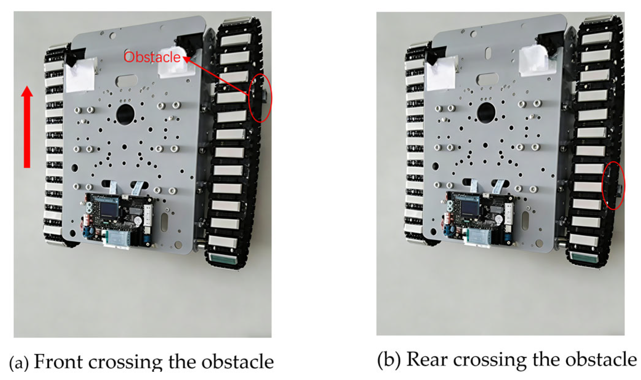
To verify the improvement effect of the proposed anti-overturning module on the obstacle-crossing performance, an experiment without the anti-overturning module was carried out, as shown in Figure 11. The experimental results show that the robot without the anti-overturning module can climb over a maximum obstacle height of 16 mm. When the obstacle height exceeds 16 mm, the robot exhibits a tendency toward rearward overturning once the front end is lifted, leading to instability. By comparing the maximum obstacle-crossing heights, it can be found that the anti-overturning module improves the robot’s obstacle-crossing performance by approximately 43%.

5.2.2. Continuous Obstacles-Crossing Experiment

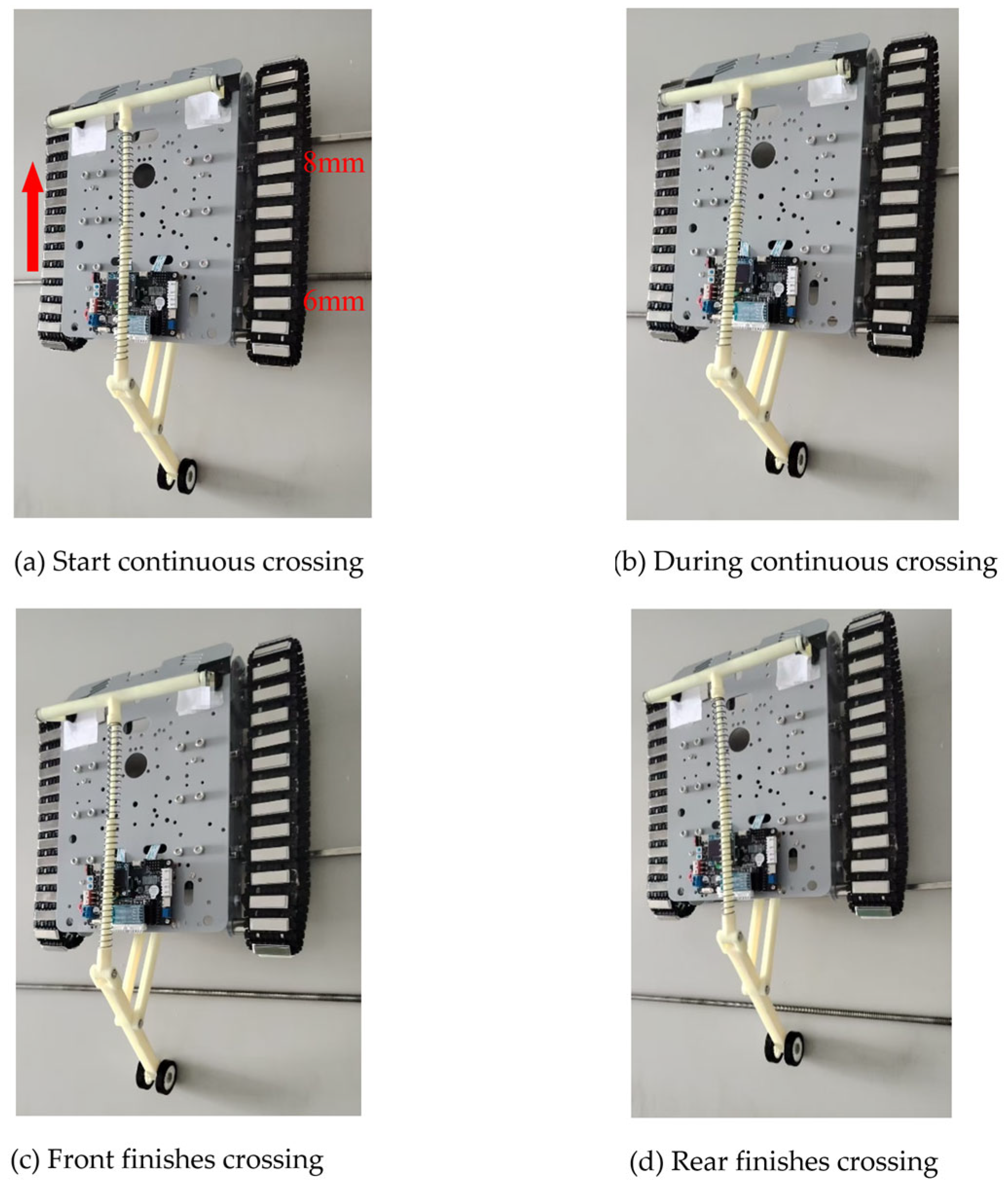
In the continuous obstacles-crossing experiment, two continuous obstacles with heights of 6 mm and 8 mm were set up at an interval of 120 mm. The wall-climbing robot continuously and stably climbed over these two obstacles at a speed of 30 mm·s−1, as shown in Figure 12. The adaptive tracked mobility module can dynamically compensate for the change in track length caused by the continuous obstacles, thereby maintaining stable adhesion. As the obstacle height varies, the spring compression stroke adjusts accordingly, and the provided anti-overturning moment is regulated concurrently. Experimental results demonstrate that when the robot climbs over continuous obstacles within a short period, its adaptive tracked mobility module and anti-overturning module exhibit excellent adaptability to continuous obstacles, along with outstanding coordination and rapid reset capability.

5.2.3. Uneven Wall-Climbing Experiment

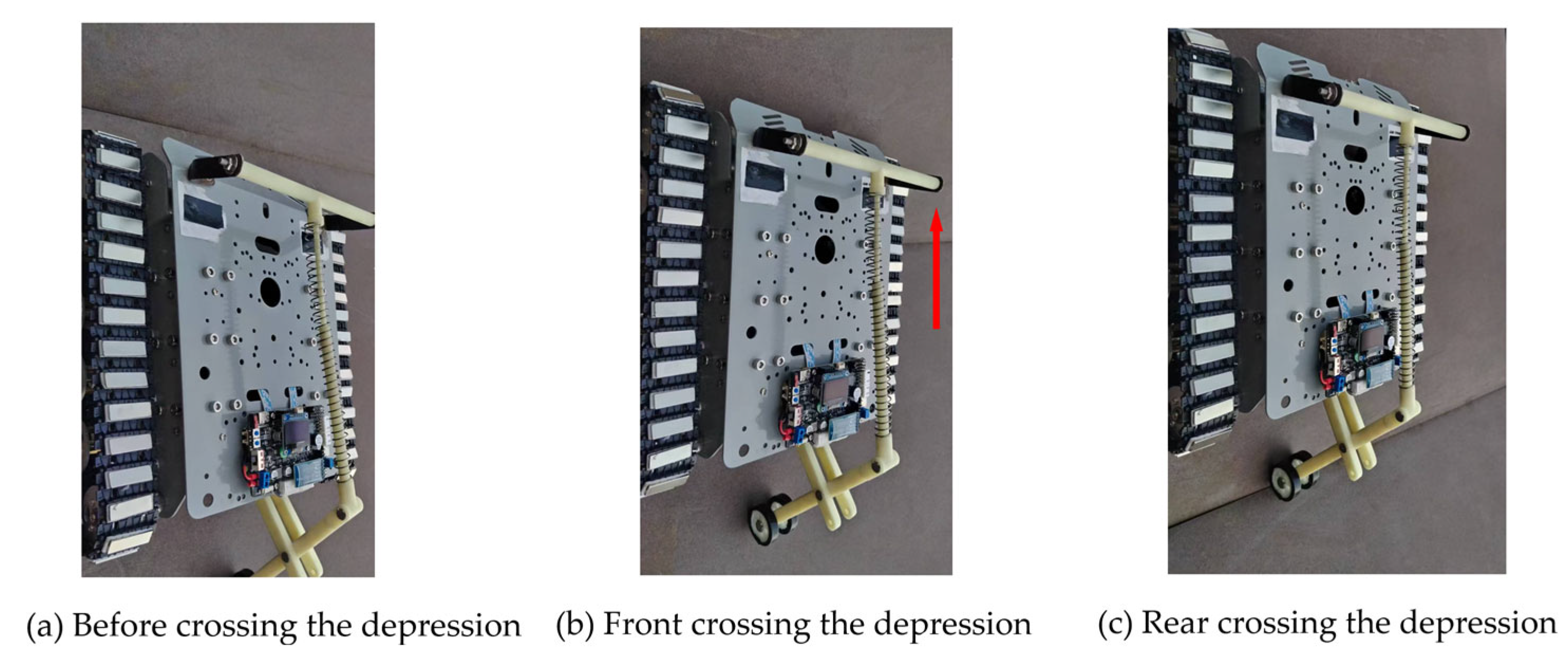
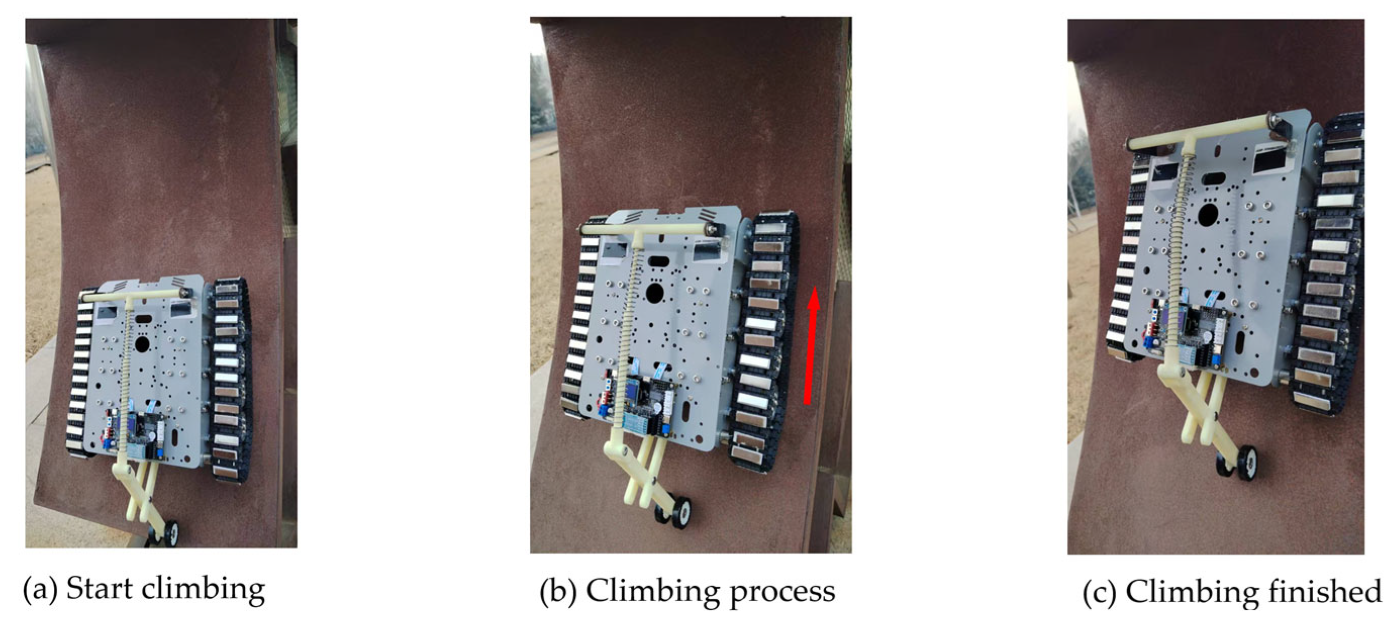
To verify the adaptive performance of the robot on uneven walls, wall-climbing experiments were conducted on three types of typical uneven walls: a 160° obtuse triangular protrusion, a 160° obtuse triangular depression, and a curved surface, as shown in Figure 13, Figure 14 and Figure 15. The experiments demonstrate that the adaptive tracked mobility module and anti-overturning module exhibit good adaptability to protrusions, depressions and curved surfaces, enabling stable adhesion and reliable motion on uneven vertical walls.

6. Conclusions

This paper presents a new type of magnetic wall-climbing robot featuring a passive adaptive tracked mobility module and a link-spring anti-overturning module. The adaptive module enables the tracks to adjust their effective contact length and shape in response to the geometric features of the wall surface. The anti-overturning module provides the robot with an anti-overturning moment during obstacle crossing. Parametric modeling and simulation analysis were conducted to investigate the influence of parameters of the anti-overturning module on the anti-overturning moment. Prototype experiments demonstrate that the robot can overcome a single obstacle with a maximum height of 23 mm, stably climb over continuous obstacles, and move on uneven vertical walls, which verifies the effectiveness of the mechanism design. Through this innovative mechanical design, the robot’s obstacle-crossing capability and motion stability on vertical walls are significantly enhanced without the need for additional drivers or control units.
This paper focuses on analyzing the functions of the adaptive tracked mobility module and the anti-overturning module. In future research, we will conduct systematic studies on the robot’s payload capacity and perform comprehensive optimization to improve its overall performance. As part of this effort, the particle swarm optimization algorithm can be employed for multi-objective parameter optimization to determine the permanent magnetic adhesion unit arrangement and unit dimensions of the adaptive tracked mobility module, as well as the link dimensions and spring stiffness of the anti-overturning module. Additionally, combined with high-strength lightweight materials such as carbon fiber composites, topology optimization can be introduced to achieve lightweight design of the robot’s main structure, thereby reducing its weight and further enhancing its payload capacity and motion stability.

Author Contributions

Conceptualization, S.Z.; methodology, S.Z.; software, G.Q.; validation, H.D.; formal analysis, G.Q.; investigation, H.D.; resources, H.D.; data curation, H.C.; writing—original draft preparation, S.Z.; writing—review and editing, S.Z.; visualization, G.Q.; supervision, H.D.; project administration, H.D.; funding acquisition, S.Z. All authors have read and agreed to the published version of the manuscript.

Funding

This research was funded by the Undergraduate Training Program for Innovation and Entrepreneurship (Grant No. S202510225299) and the Heilongjiang Provincial Natural Science Foundation Project (Grant No. LH2019F003).

Data Availability Statement

The data supporting the findings of this study are available from the corresponding author upon reasonable request.

Acknowledgments

The authors have reviewed and edited the output and take full responsibility for the content of this publication.

Conflicts of Interest

The authors declare no conflicts of interest.

References

  1. Tao, B.; Gong, Z.Y.; Ding, H. Climbing robots for manufacturing. Natl. Sci. Rev. 2023, 10, nwad042. [Google Scholar] [CrossRef]
  2. Gu, J.; Wang, C.; Wu, X. Self-adjusted adsorption strategy for an aircraft skin inspection robot. J. Mech. Sci. Technol. 2018, 32, 2867–2875. [Google Scholar] [CrossRef]
  3. Yao, C.; Yin, C. Multi-objective optimization of negative pressure adsorption system using FSI and NSGA-III. J. Mech. Sci. Technol. 2025, 39, 5223–5235. [Google Scholar] [CrossRef]
  4. Kim, H.; Kim, D.; Yang, H.; Lee, K.; Seo, K.; Chang, D.; Kim, J. Development of a wall-climbing robot using a tracked wheel mechanism. J. Mech. Sci. Technol. 2008, 22, 1490–1498. [Google Scholar] [CrossRef]
  5. Chen, Z.; Ren, L.; Chen, S.; Zhang, H.; Li, F.; Wang, G. A low energy consumption wall climbing robot with passive impactive negative pressure adhesion. Eng. Res. Express 2024, 6, 025513. [Google Scholar] [CrossRef]
  6. Santos, D.; Heyneman, B.; Kim, S.; Cutkosky, M.R. Gecko-inspired climbing behaviors on vertical and overhanging surfaces. In Proceedings of the IEEE International Conference on Robotics and Automation (ICRA), Pasadena, CA, USA, 19–23 May 2008; pp. 1983–1988. [Google Scholar]
  7. Birkmeyer, P.; Gillies, A.G.; Fearing, R.S. Dynamic climbing of near-vertical smooth surfaces. In Proceedings of the 2012 IEEE/RSJ International Conference on Intelligent Robots and Systems, Vilamoura-Algarve, Portugal, 7–12 October 2012; pp. 3322–3328. [Google Scholar]
  8. Xu, B.; Wang, X. Optimization design of electrostatic adhesion films: Based on theoretical modeling and experimental verification. J. Electrost. 2025, 135, 104067. [Google Scholar] [CrossRef]
  9. Hawkes, E.W.; Christensen, D.L.; Cutkosky, M.R. Vertical dry adhesive climbing with a 100× bodyweight payload. In Proceedings of the 2015 IEEE International Conference on Robotics and Automation (ICRA), Seattle, WA, USA, 26–30 May 2015; pp. 5228–5233. [Google Scholar]
  10. Sabermand, V.; Ghorbanirezaei, S.; Hojjat, Y. Testing the application of Free Flapping Foils (FFF) as a method to improve adhesion in an electrostatic wall-climbing robot. J. Adhes. Sci. Technol. 2019, 33, 2579–2594. [Google Scholar] [CrossRef]
  11. Liu, Y.; Seo, T.W. Any Climb-II: Dry-adhesive linkage-type climbing robot for uneven vertical surfaces. Mech. Mach. Theory 2018, 124, 197–210. [Google Scholar] [CrossRef]
  12. Liu, Y.; Lee, D.G.; Kim, H.G.; Seo, T.W. Compliant wall-climbing robotic platform for various curvatures. In Proceedings of the 2015 IEEE/RSJ International Conference on Intelligent Robots and Systems (IROS), Hamburg, Germany, 28 September–2 October 2015; pp. 4996–5001. [Google Scholar]
  13. Liu, Y.; Lim, B.; Lee, J.W.; Park, J.; Kim, T.; Seo, T. Steerable dry-adhesive linkage-type wall-climbing robot. Mech. Mach. Theory 2020, 153, 103987. [Google Scholar] [CrossRef]
  14. Xu, Y.H.; He, K.; Zhao, W.L.; Liu, Y. A novel design of a wall-climbing robot and experimental study on magnetic wheels. In Proceedings of the 2021 International Conference on Computer, Control and Robotics (ICCCR), Shanghai, China, 8–10 January 2021; pp. 60–65. [Google Scholar]
  15. Wang, C.; Zhu, S.; Song, W.; Zheng, T.; Ding, H.; Wang, B. Modeling of attractive force of magnetic wheel under different wall structure and attitude used for climbing robot. J. Mech. Sci. Technol. 2024, 38, 411–421. [Google Scholar] [CrossRef]
  16. Peidró, A.; Tavakoli, M.; Marín, J.M.; Cabrera, J.A. Design of compact switchable magnetic grippers for the HyReCRo structure-climbing robot. Mechatronics 2019, 59, 199–212. [Google Scholar] [CrossRef]
  17. Zhu, S.Q.; Gao, Z.F.; Song, W.; Liu, Y. Dynamics modelling of process of surmounting weld seam by wall-climbing robot. Trans. Chin. Soc. Agric. Mach. 2020, 51, 377–383. [Google Scholar]
  18. Xu, H.; Han, Y.; He, M.; Li, Y.; Guo, W. NuBot: A magnetic adhesion robot with passive suspension to inspect the steel lining. Chin. J. Mech. Eng. 2023, 36, 90. [Google Scholar] [CrossRef]
  19. Wu, M.H.; Pan, G.; Zhang, T.; Chen, Y.Q. Design and optimal research of a non-contact adjustable magnetic adhesion mechanism for a wall-climbing welding robot. Int. J. Adv. Robot. Syst. 2013, 10, 63. [Google Scholar] [CrossRef]
  20. Cui, S.; Pei, X.; Song, H.; Wang, L. Design and motion analysis of a magnetic climbing robot applied to ship shell plate. Machines 2022, 10, 632. [Google Scholar] [CrossRef]
  21. Zhang, X.J.; Wu, Y.Q.; Liu, H.X.; Li, Z.H. Design and analysis of wheel-footed magnetic adsorption wall-climbing robot with passing obstacles capability. J. Mech. Eng. 2024, 60, 248–261. [Google Scholar]
  22. Schmidt, D.; Berns, K. Climbing robots for maintenance and inspections of vertical structures—A survey of design aspects and technologies. Robot. Auton. Syst. 2013, 61, 1288–1305. [Google Scholar] [CrossRef]
  23. Gao, M.Z.; Huang, M.; Tang, K.; Chen, Y.L. Design, analysis, and control of a multilink magnetic wheeled pipeline robot. IEEE Access 2022, 10, 67168–67180. [Google Scholar] [CrossRef]
  24. Gao, F.; Fan, J.; Zhang, L.; Jiang, J.; He, S. Magnetic crawler climbing detection robot basing on metal magnetic memory testing technology. Robot. Auton. Syst. 2020, 125, 103468. [Google Scholar] [CrossRef]
  25. Seo, T.; Sitti, M. Tank-like module-based climbing robot using passive compliant joints. IEEE/ASME Trans. Mechatron. 2013, 18, 397–408. [Google Scholar] [CrossRef]
  26. Hu, J.; Han, X.; Tao, Y.; Feng, S. A magnetic crawler wall-climbing robot with capacity of high payload on the convex surface. Robot. Auton. Systems 2024, 148, 103907. [Google Scholar] [CrossRef]
  27. Wang, G.; Li, W.; Che, H. Design and analysis of anti-overturning mechanism for magnetic wall-climbing robot. J. Mech. Sci. Technol. 2024, 38, 379–387. [Google Scholar] [CrossRef]
  28. Ji, H.; Li, P.; Wang, Z. Analysis and Simulation of Permanent Magnet Adsorption Performance of Wall-Climbing Robot. Actuators 2024, 13, 337. [Google Scholar] [CrossRef]
  29. Tang, D.L.; Long, Z.Y.; Yuan, B.; Ding, R.S.; Zhang, J.Y. Analysis of Mechanics and Power Consumption of Wall-climbing Robot with Permanent Magnet Adsorption Wheel. Mech. Sci. Technol. Aerosp. Eng. 2019, 38, 499–506. [Google Scholar]
Figure 1. The overall structure diagram of the robot.
Machines 14 00439 g001
Figure 2. Structure diagram of the adaptive tracked mobility module of the robot. (1. Driving wheel, 2. Link, 3. Belt press wheel, 4. Frame, 5. Spring rod, 6. Tracks embedded with permanent magnetic adhesion units, 7. Linear groove, 8. Pre-compressed spring tensioning mechanism, 9. Driven wheel, 10. Wall). The yellow arrow indicates the moving direction of the robot.
Machines 14 00439 g002
Figure 3. Structure diagram of the anti-overturning module of the robot. (1. Link P, 2. Spring rod, 3. Link Q, 4. Support swing rod, 5. Magnetic roller). The yellow arrow indicates the moving direction of the robot.
Machines 14 00439 g003
Figure 4. Schematic diagram of structural transformation during the robot’s obstacle-crossing process. The yellow arrows indicate the moving direction of the robot and the red arrows indicate the moving direction of the links.
Machines 14 00439 g004
Figure 5. Schematic diagram of the parametric structure of the robot on a flat wall. The yellow arrow indicates the moving direction of the robot. The robot configuration before crossing is shown in blue, and the configuration with the front crossing the obstacle is shown in green.
Machines 14 00439 g005
Figure 6. Schematic diagram of the parametric structure of the robot on an uneven wall. The yellow arrows indicate the moving direction of the robot.
Machines 14 00439 g006
Figure 7. Relationship curve between FN and K.
Machines 14 00439 g007
Figure 8. Relationship between H and Manti. Red auxiliary lines mark the coordinate values of the feature point.
Machines 14 00439 g008
Figure 9. Prototype of the wall-climbing robot.
Machines 14 00439 g009
Figure 10. The process of climbing over a 20 mm high obstacle. The red arrow indicates the moving direction of the robot.
Machines 14 00439 g010
Figure 11. The process of climbing over a 16 mm high obstacle without anti-overturning module. The red arrow indicates the moving direction of the robot.
Machines 14 00439 g011
Figure 12. The process of climbing over continuous obstacles. The red arrow indicates the moving direction of the robot.
Machines 14 00439 g012
Figure 13. The process of climbing on the wall with a 160° obtuse triangular protrusion. The red arrow indicates the moving direction of the robot.
Machines 14 00439 g013
Figure 14. The process of climbing on the wall with a 160° obtuse triangular depression. The red arrow indicates the moving direction of the robot.
Machines 14 00439 g014
Figure 15. The process of climbing on a curved surface. The red arrow indicates the moving direction of the robot.
Machines 14 00439 g015
Table 1. Designed parameters.
ParametersSize
l125 mm
l2140 mm
l367.2 mm
l472.8 mm
l569.5 mm
d163 mm
θ 45°
K5 N/mm
FS010 N
μ 0.5
δ 43 mm
Disclaimer/Publisher’s Note: The statements, opinions and data contained in all publications are solely those of the individual author(s) and contributor(s) and not of MDPI and/or the editor(s). MDPI and/or the editor(s) disclaim responsibility for any injury to people or property resulting from any ideas, methods, instructions or products referred to in the content.