Review

Friction Stir Welding: A Critical Review of Analytical, Numerical, and Experimental Methods for Quantifying Heat Generation


1
Department of Mechanical Engineering (Production and Design), Shoubra Faculty of Engineering, Benha University, Benha 13512, Egypt
2
Mechanical Engineering Department, College of Engineering at Al Kharj, Prince Sattam Bin Abdulaziz University, Al Kharj 11942, Saudi Arabia
3
Department of Metallurgical and Materials Engineering, Faculty of Petroleum and Mining Engineering, Suez University, Suez 43221, Egypt
4
Department of Mechanical Engineering, College of Engineering, Imam Mohammad Ibn Saud Islamic University (IMSIU), Riyadh 11432, Saudi Arabia
*
Author to whom correspondence should be addressed.
Machines 2026, 14(4), 440; https://doi.org/10.3390/machines14040440
Submission received: 25 February 2026 / Revised: 9 April 2026 / Accepted: 13 April 2026 / Published: 16 April 2026

Abstract

As a solid-state welding technique, friction stir welding (FSW) has many advantages over conventional fusion welding. Its applications in the manufacturing and joining of parts in aerospace, automotive, and shipbuilding have significantly increased. Friction heat generation is the fundamental driver of the FSW process. It governs material flow, microstructural evolution, mechanical properties, and residual stresses. Understanding the effect of heat generated on the joint quality is essential for process parameter optimization, ensuring defect-free welds and high-quality joints. Thus, evaluating the thermal history of the FSW process is a key requirement for effective analysis. This comprehensive review critically discusses research studies published over the past three decades (1991–2025) that have examined different approaches to predict and measure heat generation in FSW. A total of 136 highly relevant articles were selected from the Scopus database and systematically analyzed. The effects of various welding parameters on heat generation, microstructural evolution, and joints’ mechanical properties have been reported. Different heat generation prediction and measurement techniques, such as analytical models, finite element models (FEM), and experimental methods have been discussed in terms of their feasibility, accuracy, advantages, disadvantages, and cost. The evolution, state of the art of analytical models and FEM over the last three decades are analyzed and future research directions are outlined. Finally, the correlation between process parameters, heat generated, microstructural development, and mechanical performance of the welded joints for various workpiece materials is investigated. This review provides a critical and comparative perspective that highlights the strengths and limitations of each method, offering practical guidance for researchers and industry practitioners.

1. Introduction

In 1991, friction stir welding (FSW), a solid-state welding method, was developed by the Welding Institute (TWI) [1]. Its importance in the manufacturing and fabrication sectors has increased, particularly for materials that are difficult to join using traditional fusion methods [2,3]. The heat is generated when a non-consumable rotating tool moves through a joint made of two pieces of material. The resulting localized heat diminishes the material’s yield strength, allowing it to be mechanically stirred into a unified bond without the occurrence of melting. This technique has been successfully used to join various materials, including copper [4,5], magnesium [6], titanium [7,8], aluminum [9,10,11,12], and certain high-strength steels [13,14]. Unlike traditional welding processes that rely on heat to melt the base materials, FSW is a solid-state process that minimizes thermal distortion and porosity, leading to high-quality welds with exceptional mechanical characteristics [15]. The process’s efficiency and ability to join dissimilar and difficult-to-weld materials make it a good alternative for numerous industries, including aerospace, automotive, and shipbuilding [16,17,18,19]. Importantly, FSW’s basic mechanism (the creation of localized heat input coupled with extreme plastic deformation from the stirring action of the tool) allows for applications beyond simple joining. The ability to modify as-cast microstructures to heal defects [20] and guarantee the even dispersion of ceramic reinforcement particles for the production of advanced metal matrix composites is made possible by this localized energy and intense mixing [21]. The process is often referred to as Friction Stir Processing (FSP) when it is applied to this particular material modification and composite fabrication.
Successful FSW depends on the efficient generation of heat to enable effective material deformation. This essential thermal energy is derived from a dual-source mechanism: the frictional resistance at the interface between the rotating tool and the workpiece, complemented by the heat released during the severe plastic deformation of the stirred material. [22]. The applied axial force, material properties, tool geometry, traverse (welding) speed, and tool rotational rate all affect the frictional and plastic heat generation [23,24]. Since the material’s highest temperature usually doesn’t rise over its solidus temperature, melting doesn’t seem to occur during the welding process. The material does, however, undergo considerable thermal softening, especially in the regions near to the tool. The stir zone (SZ), heat-affected zone (HAZ), and thermo-mechanically affected zone (TMAZ) are among the weld zones where distinct microstructures are produced by the thermal cycles involved in the FSW process. These microstructural changes then have an impact on the final weld’s mechanical characteristics, including strength, ductility, and fatigue resistance. While too much heat can result in unwanted effects such as excessive tool wear, reduced mechanical quality, and grain growth, too little heat can result in incomplete bonding and volumetric defects. Consequently, maintaining the integrity of the welded joint and improving the welding process depends on managing heat input.
To enhance the FSW process, various techniques have been used to regulate heat input. These consist of adjusting the axial forces, tool rotational rate, welding speeds, and tool geometry. For instance, tool design can significantly affect material flow and heat generation efficiency. The size of the pin and shoulder, as well as the geometry of the FSW tool, greatly affects the heat input. While the pin aids in material stirring and consolidation, the tool’s shoulder produces most of the frictional heat [25,26]. In general, the heat input is increased by a larger shoulder diameter or a higher tool rotation rate. The distribution of heat in the weld zone can also be impacted by tool designs with more aggressive pin profiles, which can change the temperature distribution and the microstructure [27]. By better distributing the heat, a tool with an ideal shoulder diameter and pin geometry lowers the possibility of overheating or insufficient bonding.
The thermal energy produced by friction is directly correlated with the tool’s rotating speed. By increasing the spindle speed, the friction-induced heat input is amplified, facilitating a more significant thermal rise within the localized SZ. On the other hand, overheating brought on by extremely high rotational rates might result in defects such as material degradation or tool wear [28,29,30]. Likewise, the heat input is also influenced by the welding speed, defined as the rate at which the tool traverses the joint line. A greater welding speed lowers the heat input by shortening the time that the tool and material interact, whereas a lower feed rate permits the tool to stay in touch with the material for a longer amount of time, producing more heat [15,31]. Moreover, process parameters such as tool tilt angle [32], plunge depth [33], cooling methods [34], and material properties have an impact on the generated heat input.
Because of the extremely uneven temperature distribution throughout the weld zone, accurately monitoring heat input during FSW is a challenging operation. Numerous techniques, such as thermocouple-based measurements and infrared thermography, have been developed to experimentally measure the heat generation during the FSW process [35,36]. Usually, thermocouples are attached to the surface or embedded in the workpiece to measure the temperature during the welding process. However, this approach might not fully capture the temperature profile, particularly in difficult to reach regions such as SZ and TMAZ. Infrared thermography is another non-contact technique that provides a high-resolution, real-time temperature distribution of the welded zone. This method is particularly beneficial for figuring out regions with excessive heat generation and comprehending the dynamic thermal behavior during FSW [37].
Mathematical models and finite element models (FEM) were other invaluable tools for estimating the heat generation and its effects on the welded joint quality. Mathematical models simplify FSW physics into governing equations. These governing equations include heat transfer equations, mechanical equations, and material flow equations [38,39,40,41,42,43,44]. On the other hand, FEM numerically solves coupled thermomechanical equations by discretizing the weld zone into tiny elements. FEM technique enables virtual experimentation to optimize tool geometry, welding speed, and tool rotational rate to reduce defects such as voids and cracks. It also dictates tool design and predicts residual stresses and fatigue life. Nevertheless, there are still issues with precisely simulating material behavior and tool-workpiece interaction [45,46,47,48,49,50,51].
From the literature, there is a lack of understanding of the different methods used to determine the heat generated during the FSW process. Based on the importance of heat generation during the FSW process and its impact on the welded joint’s quality, the present work aims to understand the different methods of determining the heat generated during the FSW process. In contrast to previous work, analytical, numerical, and experimental methods have been discussed in terms of feasibility, accuracy, advantages, disadvantages, and cost. According to the literature, the present work also gives future directions to improve the accuracy and overcome the limitations of each measurement technique. Moreover, the effect of the heat generated on the microstructure evolution and mechanical properties of the FSW of different alloys has been discussed and summarized.

2. Review Method

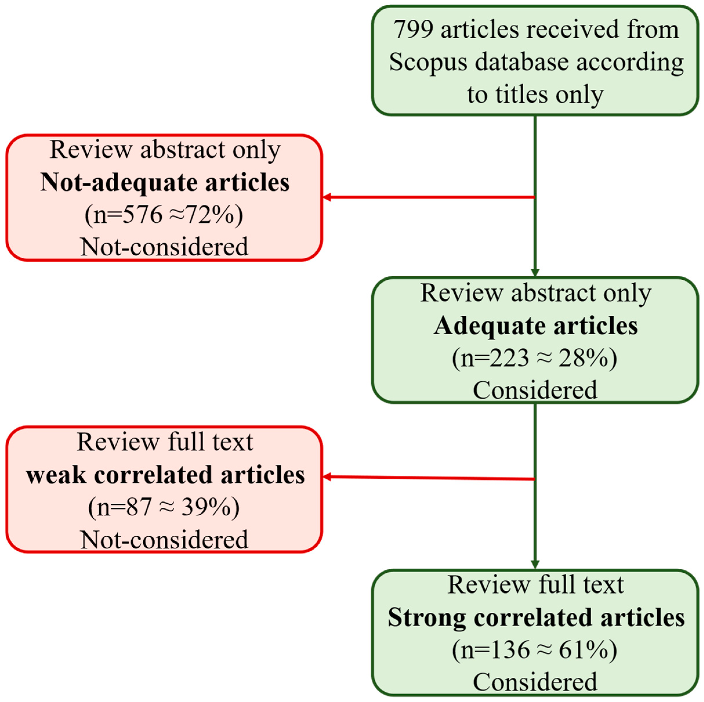
The literature search was conducted using the Scopus database, covering the period from 1991 (the year FSW was invented) to 2025. Two independent teams from the authors were set to screening of all articles about heat generation during FSW process according to Scopus database. The articles were marked using “yes” or “no”. As shown in Figure 1, three stages of articles’ screening were used. In the first stage, articles were screened only with their titles. In the second stage, articles marked with no-no or yes-no were considered as not-adequate articles, while the adequate articles were marked as yes-yes. The full text of the adequate articles was reviewed in the third stage. The rejected articles (weak correlated articles) were marked as no-no or yes-no, while the strong correlated articles were marked as yes-yes. The strong correlated articles were then used in the present review article.

3. Analytical Models

Understanding and optimizing FSW requires precise predictions of heat generation and temperature distribution. Heat controls residual stresses, tool wear, material flow, microstructural evolution, and, in final form, weld quality. Although experimental temperature measurement yields useful information, it has a low spatial resolution and is difficult to use when welding at high speeds. Although Finite Element Analysis provides detailed simulations, it is computationally costly and necessitates a high level of expertise [52]. This gap is filled by analytical models. They offer quick, physically intuitive insights into the mechanisms of heat generation and thermal cycles by providing closed-form mathematical solutions based on basic physics concepts, such as heat conduction, contact mechanics, and plasticity. Analytical models are very useful for understanding scaling effects, optimizing parameters, designing initial processes, and creating benchmarks for more intricate numerical models [53,54,55].

3.1. Evolution of Analytical Models

The development of analytical models has been substantial, moving from basic approximations to complicated formulations that take into account intricate physics.

3.1.1. Early Moving Heat Source Models

Early analytical methods converted classical moving heat source solutions, most notably Rosenthal’s welding equations, to FSW. According to these models, the FSW tool moved with the traverse speed and was either a concentrated or dispersed heat source. Rosenthal [56] developed an analytical solution to model the heat distribution using a moving point heat source. The quasi-steady-state temperature field (T) in a thick plate is given as follows:
T ( x ,   y ,   z ) =   T o + Q 2 π K r     e x p ( V ( r + x ) 2 α )
where To, Q, K, r, V, x, and α are the initial temperature of the material, the power of the heat source, the thermal conductivity of the material, the radial distance from the heat source, the velocity of the moving heat source, the distance ahead of the source in the welding direction, and the thermal diffusivity of the material, respectively. Despite being computationally simple, this model significantly oversimplifies FSW by neglecting material flow, convection and radiation heat transfer, the distributed nature of the heat source (shoulder and pin), and the distinction between heat input and heat creation.
With the analytical model development, researchers modeled the shoulder as a homogeneous circular heat source of radius Rsh (D/2) traveling at a velocity v after realizing its dominance. This model is called the uniform disc source model. Over the disk area, point source solutions are integrated as part of the solution. Fourier transforms or Green’s functions are used to derive the temperature field. Despite being superior to a point source, this model ignored the non-uniform pressure distribution beneath the shoulder, the pin, and the heat from plastic deformation. Although it failed close to the weld line, it gave accurate estimates of peak temperatures further from the tool [57].

3.1.2. Tool Geometry and Contact Mechanics Models

The following generation of analytical models addressed contact conditions at the interfaces and explicitly considered tool geometry. The heat produced at the tool-workpiece interaction is the main focus of these models. Considering the tool shoulder and pin design, they suppose heat is produced by frictional sliding, sticking, or a combination. Gadakh and Adepu [43] developed a heat generation model to study the effect of the tool pin shape on the heat generation. They assumed a uniform contact shear stress, sliding condition at the tool-workpiece contact surfaces, and no heat generation due to plastic deformation. They found that the heat generation from shoulder ( Q s h ), from pin sided ( Q p )n and from the pin tip ( Q p t ) can be expressed as follows:
Q s h =   2 3   π ω τ c o n t a c t ( R s h 3   R p r 3 )
Q p = π ω τ c o n t a c t 2   ·   H p i n cos α   ·   ( R p t + R p r ) 2
Q p t = 2 3   π ω τ c o n t a c t ·   R p t 3
Q T = Q s h + Q p + Q p t
where Q T is the total heat generated, ω is the angular velocity, τcontact is the contact shear strength, R s h is the shoulder diameter, R p t is the pin tip diameter, R p r is the pin root diameter, H p i n is the pin length, and α is the pin taper angle (°). They also reported that the heat generated decreased with increasing the taper angle of the tool pin.
Bhadle et al. [44] derived simplified equations to determine the heat input at the tool shoulder, pin side, and pin tip surfaces for various tapered tool pin profiles, including hexagonal (HEX), square (SQ), pentagonal (PEN), and triangular (TR). They used the equations to assess the temperature change during the FSW process using COMSOL 5.1 software and validate the results. They reported that the heat generation and peak temperature increased with an increasing number of side edges on the tool pin.
Rajiv et al. [40] presented two analytical models to model the heat generation during FSW. The first model, a genetic algorithm using MATLAB 8.4 software, is developed to estimate the heat generation by cylindrical and tapered pin profiles. The second model, named the regression model using MINTAB-17, was derived to determine the optimum tool design for FSW aluminum alloys. The researchers found that the tapered cylindrical pin generated more heat than the cylindrical pin profile. Additionally, the shoulder surface of the tool generates approximately 85% of the heat, while around 15% of the heat is produced by the pin tip and side surfaces of the tool. Moreover, they found that a tool rotation rate of 250 rpm, a pin diameter of 4 mm, and a shoulder diameter of 12 mm represent the optimum values for efficient tool design.
Contact condition is the most significant aspect of the numerical model when simulating the FSW process. The shear forces between the tool surface and the matrix are described in this instance using the Coulomb law of friction. The law typically calculates the contact shear stress ( τ f r i c t i o n ) as:
τ f r i c t i o n =   μ σ
where µ is the coefficient of friction and σ is the contact stress. Coulomb’s law is typically interpreted in terms of rigid contact pairings, independent of internal stress. Thus, this isn’t accurate enough for this model. As a result, a more FSW-specific legal interpretation is provided. The three contact states listed below are defined for the FSW process:
(a)
Sticking condition: In numerical modeling of FSW, the sticking regime represents a boundary condition at the tool-workpiece interface. It is characterized by the interfacial shear stress reaching the yield shear stress of the deforming material. This leads to a no-slip condition where the material velocity at the interface matches the local tool velocity. The resulting mechanical equilibrium balances the rotational driving force with the material’s plastic resistance. This concept is central to advanced friction models, often implemented as a limiting case in mixed stick-slip formulations, where the contact stress is defined by the workpiece’s temperature and strain-rate dependent yield strength rather than a simple friction law.
(b)
Sliding condition: Sliding occurs at the tool-workpiece interface when the imposed contact shear stress cannot overcome the material’s resistance to yield. The resulting deformation is purely elastic and localized. Under this condition, the internal elastic shear stress developed in the material rises to match the magnitude of the dynamic contact shear stress, creating a force balance that allows for continuous relative motion without permanent bonding or bulk material transport.
(c)
partial sliding/sticking: Partial sliding/sticking is the prevalent intermediate condition where the tool-workpiece interface experiences neither full adhesion nor complete Coulombic sliding. The contact shear stress reaches a critical value equal to the material’s yield strength, causing continuous plastic shear in a localized zone. Consequently, the average velocity of material at the interface is a fraction of the tool’s velocity. This mixed state results in a dynamic equilibrium where the frictional driving stress is in balance with the material’s resistance to plastic flow [58].
According to the previous explanation of the three contact conditions, the contact state variable ( δ ) can be defined using the velocity of the matrix surface relative to the velocity of the tool surface. This variable represents the dimensionless slip rate, which is defined as follows:
δ =   V m a t r i x V t o o l = 1   γ ˙ V t o o l
γ ˙ = V t o o l V m a t r i x
where γ ˙ is the slip rate, and V t o o l is the tool velocity, which is position dependent. Researchers often assume a constant slip rate to simplify the analytical model [59]. However, more accurate calibration of the slip rate is typically achieved by combining experimental measurements, such as tool torque, axial force, and temperature profiles with many simulation trials to tune the slip rate until reasonable agreement between numerical and experimental results is obtained [59,60].
Durdanovic et al. [42] derived an analytical model to estimate the heat generation during the different FSW process phases. They defined the contact conditions at the tool/workpiece interface to be pure sliding, pure sticking or a combination. They reported that by assuming either a sliding or a sticking state, the analytical heat generation estimate correlates with the experimental heat generation. The experimental heat generation is estimated for the sliding condition using a friction coefficient that is within the acceptable range of known metal-to-metal contact values. Using the sticking condition, which describes the material of the weld piece at high temperatures, the numbers are correlated. However, the main process uncertainties occur when the welding condition combines sticking and sliding. The primary causes of the discrepancy between the analytical and experimental results in this case are assumptions of fixed shear stress, contact pressure, and coefficient of friction during the welding process. The authors proposed that advanced methods such as fuzzy logic and artificial intelligence may improve predictive accuracy during sliding/sticking contact conditions.
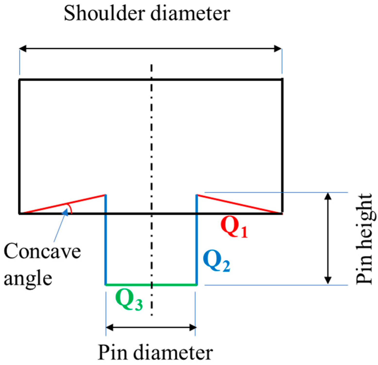
Schmidt and Hattel [58] derived three different analytical models based on sticking condition ( δ = 1), sliding condition ( δ = 0), and partial sliding/sticking condition. For simplification of the model, they assumed a simple conical tool shoulder with a flat cylindrical pin, as shown in Figure 2. The figure indicated that the total heat generation is Qt = Q1 + Q2 + Q3, where Q1 is the heat generated beneath the shoulder, Q2 is the heat generated by the pin side surface, and Q3 is the heat generated by the tool pin tip. With modifications for the particular contact state and tool geometry, the heat generation is calculated by integrating shear stress over the tool’s contact surfaces (shoulder, pin side, and pin tip). They validated the model using experimental results such as tool torque and plunge force. They reported that the sticking or near-sticking condition is most likely present at the tool/workpiece interface during FSW.
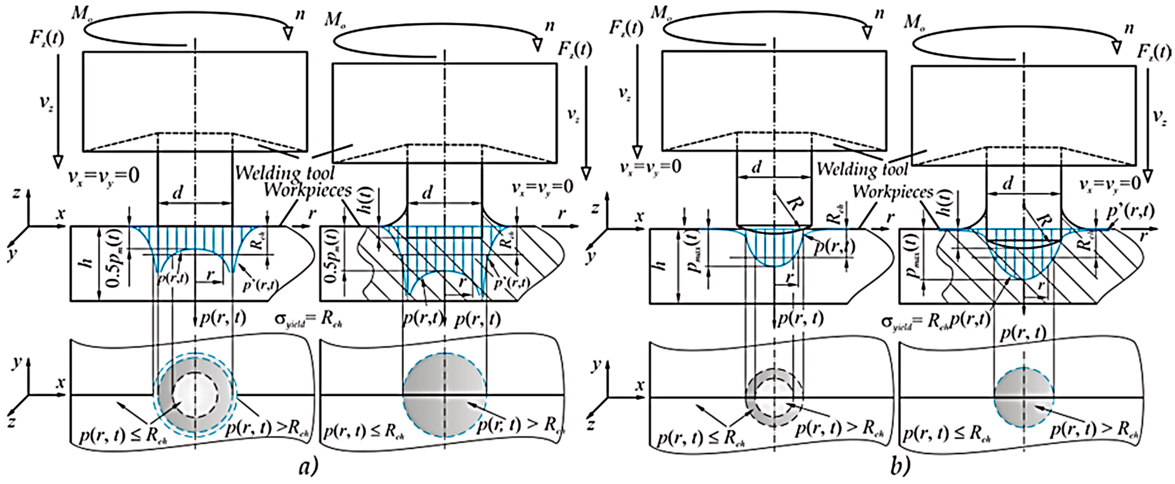
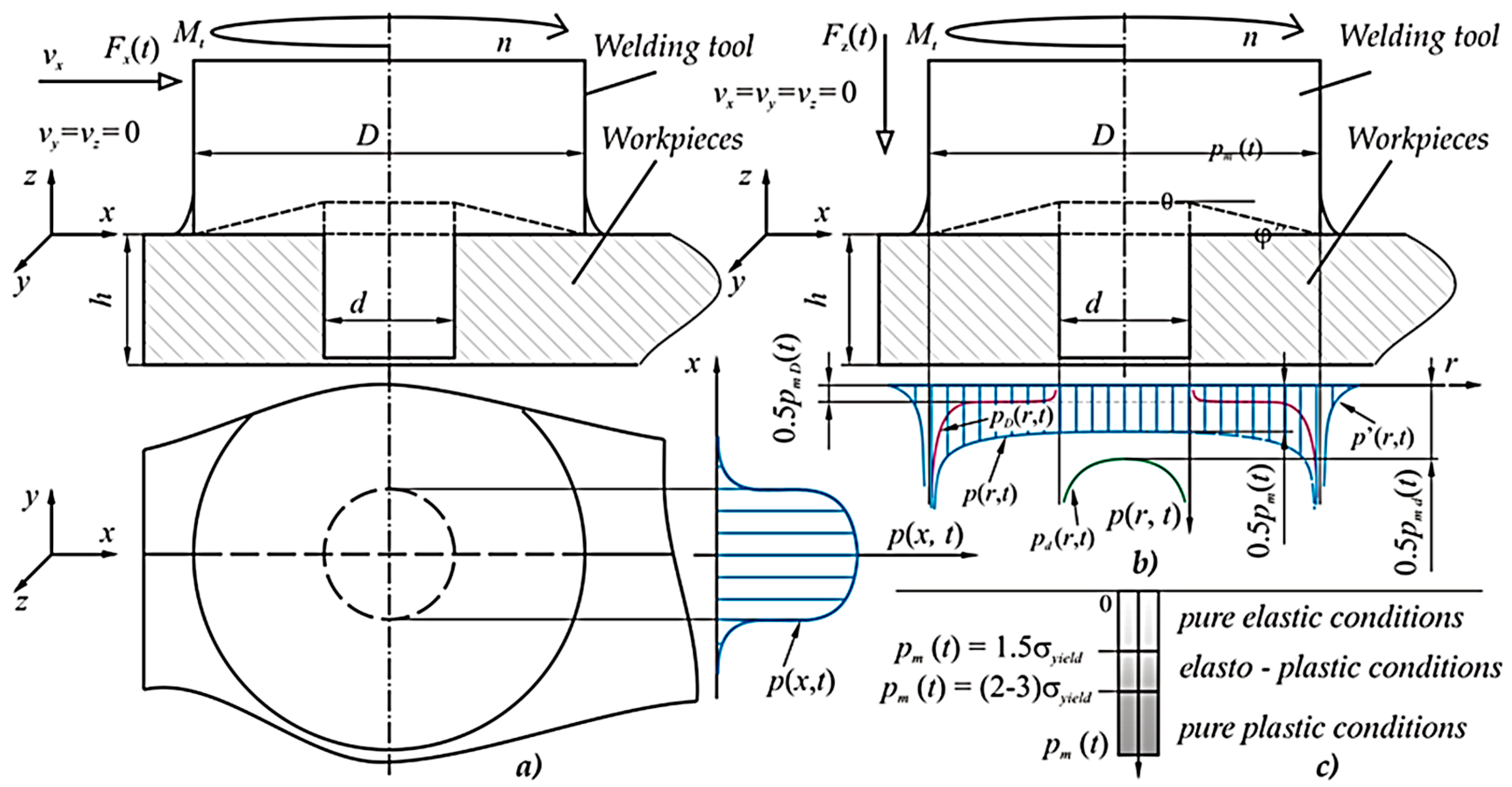
Similarly, Mijajlovic et al. [61] and Mijajlović and Milčić [62] presented an analytical model considering the same tool surfaces, i.e., tool shoulder, pin side, and pin tip surfaces. However, they consider flat pin tip (Figure 3a) and spherical pin tip (Figure 3b). They also did not assume constant contact pressure, but they estimated a model to determine it during the different FSW phases. At the beginning of the plunge stage, the pin tip touches the workpiece’s top surface and is bushed by the plunge force. The contact pressure for the flat and spherical pin tip can be estimated from Equations (9) and (10) [61,62]. During the welding phase, the contact pressure between the pin side and the workpiece material gets a notable value and is calculated using Equation (11), as shown in Figure 4a. When, the tool shoulder gets in contact with the workpiece material, the contact pressure distribution is shown in Figure 4b and calculated by Equation (12). They investigated that the dwell phase has a great effect on the heat generation required to heat the tool and workpiece. However, too long dwell time resulted in overheating and poor mechanical properties.
P ( r , t ) = 2 F z ( t ) d π d 2 4 r 2   ,   t o t < t s t   ,   0 r d 2
P ( t , r ) = 2 π d 2 4 r 2   3 F z ( t ) E 2 d 5 3     ,   t o t < t s t   ,   0 r d 2
P ( t ) { F x ( t ) d h ,   t 2 < t < t 3 0   ,       t t 2 ,   t t 3
P ( t , r ) = 4 F z ( t ) d ( t ) 2 π   ,   d ( t ) { = D ,                               t 1 t < t 4 d D t s t t 1 ·   ( t t s t ) + d ,   t s t t < t 1
where d is the diameter of the pin, D is the diameter of the shoulder, to is the starting time, t 1 is the time to achieve plunging, t 2 is the time to complete the dwell phase, t 3 is the time to complete the welding length, t 4 is the time to finish the second dwell before pulling out the tool, t s t is the time before the shoulder is in contact with the workpiece material, E is the modulus of elasticity, F z is the plunge force, F x is the force in the welding direction, and h is the pin height.

3.1.3. Plastic Deformation Models

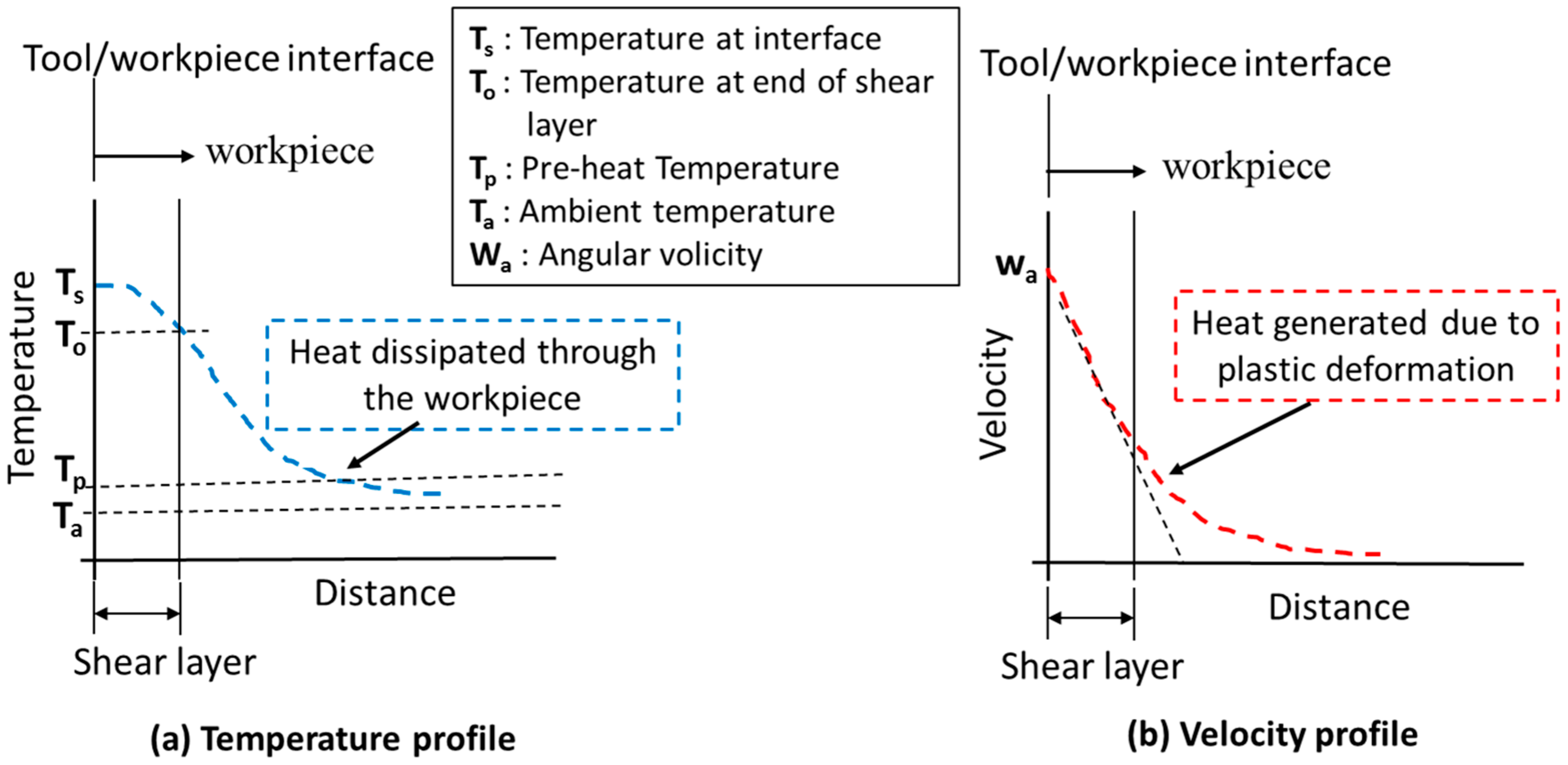
Many researchers [23,63,64,65] found that the heat generated due to plastic deformation during FSW of aluminum alloys can be neglected. The model’s accuracy necessitated the explicit consideration of plastic deformation heat, especially when utilizing stronger materials or increasing rotational speeds. A series of new closed-form scaling laws that measure the relationship between the transfer of heat and plastic deformation in FSW are presented in this study by Mendez et al. [66]. Understanding heat generation during the process requires knowledge of the maximum temperature, shear stress, and shear layer thickness surrounding the pin, all of which are provided by this information. The model seeks to provide a useful approximation for evaluating heat generation parameters across different alloy systems in FSW. The temperature profile in the shear layer in Figure 5 shows that the heat loss to the tool is minimal in cases of high thermal efficiency like FSW of aluminum. While the temperature drops steadily from the highest point at the tool–shear layer interface to a lower point at the base metal interface. This creates two distinct regions: the shear layer with significant deformation and the base plate with little shearing [66].
Yan et al. [39,41] derived a new calculation method to estimate the heat generated owing to plastic deformation by measuring the viscoplastic heat generation during the quasi-steady state FSW phase. They assumed that the flow of material fluid is a laminar flow and neglected the inclination angle of the tool pi. In addition, they assumed a solid non-slip condition, which means the angular velocities of the material fluid near the tool pin and shoulder are equal to the angular velocities of the pin and shoulder surfaces, respectively. A novel approach to calculating the viscoplastic heat output caused by plastic flow in FSW was derived. This method depends entirely on the FSW machine’s rotation rate. The validity of this computation method is checked through several groups of FSW experimental and numerical tests. According to the findings, they found that viscoplastic heat production obtained using this computation approach ranges between 3.3% and 4.4% of the total heat input.
Table 1 illustrates a comparison between the three types of analytical models in terms of typical deviation between experimental and analytical results, and strengths and weaknesses. In addition, the table shows the inputs and outputs that each model type focuses on.

3.2. Gaps and Limitations in Analytical Models

From the previous studies, the gaps and limitations of the analytical models dealing with the estimation of the heat generation during the FSW process can be concluded as follows:
  • Oversimplified material behavior: most studies assumed constant material properties such as thermal conductivity, specific heat and flow stress, while these properties are highly temperature dependent and strain-rate sensitivity. Another assumption, such as perfect plastic behavior and neglecting the phase transformation affects the accuracy of the model.
  • Inadequate Representation of Tool-Workpiece Interaction: many assumptions, such as pure sliding or pure sticking contact conditions, simplified tool geometry, and uniform contact pressure are some disadvantages of the analytical models of the FSW process.
  • Limited Multiphysics coupling: most models calculated the heat generation independently based on friction and deformation assumptions neglecting the effect of heat generation on the microstructure changes, flow stress, and thermal properties.
  • Validation and Scalability Issues: the validation of the models against limited experimental results, such as temperature and plunge force made it unreliable. Moreover, the analytical models derived for thin sheets ignore the thick sheets and the temperature gradients and transfer of the heat throughout the sheet thickness.

3.3. Future Work in Analytical Models

Developing an analytical model to describe the sticking/sliding contact condition using a temperature-, pressure-, and sliding velocity-dependent coefficient of friction is one of the promising future work directions. Moreover, extending analytical models to deal with FSW in dissimilar materials and metal matrix composites is critical. Creating progressively more complicated analytical models of the main tool characteristics (shoulder features, pin profile, and threads) and how this affects material flow velocity, contact area, and contact pressure distribution while connecting them to concepts related to heat generation is another promising direction. Furthermore, using machine learning (ML), developing scaling methodology, and defect prediction models are the most potential future directions.

4. Finite Element Models (FEM)

The intricate thermo-mechanical properties of FSW have prompted a great deal of research into process modeling. Temperature distributions, material flow, and residual stresses, all of which are challenging to quantify experimentally during the FSW process can be predicted using computational models [68]. It is essential to model the FSW process for a number of reasons. Firstly, it offers an affordable way to optimize process parameters without requiring a lot of experimental testing [69]. FSW requires a number of process parameters that interact in complex ways, which makes setting up the experiment expensive and time-consuming [70]. The impact of changing parameters on heat generation and weld quality, including tool design, welding speed, tool rotation rate, and material properties, can be simulated by computational models [71]. This makes it is possible to determine the ideal parameters for particular joint configurations and materials [72].
Second, modeling makes it possible to predict temperature histories, which are essential for understanding the mechanical characteristics of the weld joint and microstructural evolution [73]. The heat generated during FSW affects precipitation hardening, grain size, and recrystallization behavior in the weld zone [74]. Predicting temperature distributions accurately can aid in microstructure control and the achievement of desired mechanical characteristics. Finally, because of the process nature, it is challenging to monitor material flow behavior during FSW experimentally. Thus, modeling offers new perspectives on this behavior. Defects, including voids, flash, and lack of penetration are formed based on the flow of the material [75]. By modeling material flow, researchers can identify the conditions that lead to defects and develop preventive strategies.
Despite the critical importance of modeling, a number of issues make FSW a challenging subject. High strain rates, significant temperature gradients, and severe deformations are all part of the process [76]. Sophisticated constitutive models are needed since the material changes from a solid to a very viscous condition without melting. Moreover, complex contact conditions involving friction and heat transmission are involved in the tool-workpiece interface. In addition, the procedure is transient and three-dimensional, requiring a large amount of computational power [53]. Researchers have used a variety of computational techniques, each with unique advantages and disadvantages, to address these issues. However, the necessity for precise and effective FSW simulations encouraged the development of these modeling techniques.

4.1. Evolution of FEM

Early models concentrated on axisymmetric or simplified 2D instances, but 3D models have grown in popularity as computational resources and numerical techniques have improved [77]. The predictive power of these models has been enhanced by the addition of sophisticated structural models, friction models, and heat generation mechanisms. The Lagrangian technique, which follows material particles, is simple to represent massive deformations but suffers from mesh distortion [78]. Eulerian approach, which fixes the mesh and allows material to flow through, was then used to prevent mesh distortion but has difficulty tracking material history [79]. The Arbitrary Lagrangian Eulerian (ALE) method combines the advantages of both by allowing the mesh to move independently of the material [80]. The coupled Eulerian Lagrangian (CEL) technique is another useful modeling method, which couples the Eulerian domain (deformed workpiece) with the Lagrangian domain (rigid tool) to handle the interaction more effectively [22]. Additionally, the validation and reliability of the simulations have been improved by combining modeling with experimental methods like infrared thermography and digital picture correlation [81].

4.1.1. Lagrangian Models

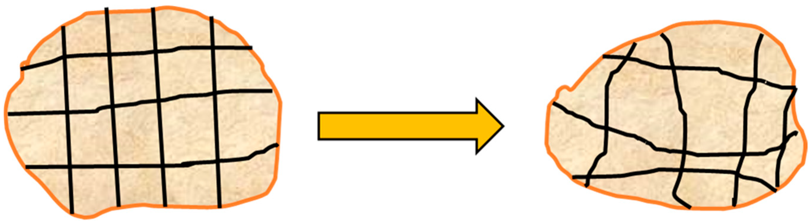
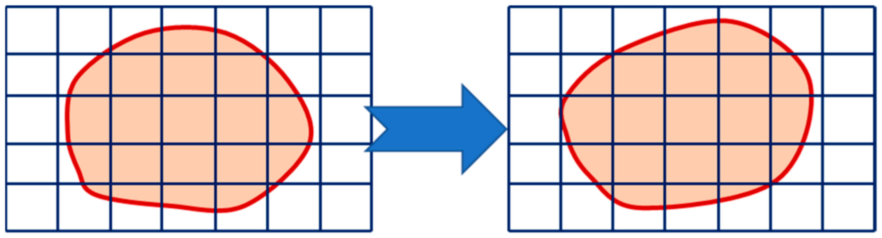
One of the first methods for simulating FSW processes was the Lagrangian description. In this system, material particles and their histories may be directly tracked while the computational mesh moves and deforms with the material [82], as shown in Figure 6. This method is very natural for solid mechanics situations when the main issue is material deformation. Every node in the computational mesh is linked to a material particle in the Lagrangian formulation, and it travels with the particle as it deforms. It is easy to trace material histories, interfaces, and boundaries because the governing equations are stated with regard to the material coordinates. Material derivatives, which track the motion of material particles, are used to represent the conservation equations for mass, momentum, and energy [83].
Shortly after the process was invented, in the mid-1990s, the first attempts to model FSW using Lagrangian methods appeared. In a groundbreaking study, McClure et al. [84] modeled the initial plunging stage using a Lagrangian finite element technique, and their predicted temperature fields agreed rather well with experimental results. Ghanimi et al. [85] reported that the Lagrangian technique produced satisfactory results on a global scale.
In contrast, Buffa et al. [86] presented a thermomechanical model inside the Lagrangian framework that made use of the finite element method using DEFORM-3D 5.0 software. The influence of welding parameters on temperature history, material flow, and strain rate, was also examined using a description of hard viscoplastic material. They investigated that the angular velocity generally influences the temperature evolution at the weld line, which is roughly symmetrical. On the contrary, welding speed and angular velocities predominate in the asymmetric material flow in the welding zone.
Dong et al. [87] developed three simplified numerical models based on the Lagrangian technique. The first one is a coupled thermo-mechanical friction heating considering Coulomb’s friction law and assuming that all the friction work was converted into heat generation. The second model was the plastic flow zone model, in which the formation of the plastic zone and its dimensions depend on the tool pin design and the thickness of the workpiece. The third one was a simplified 3-D heat generation and material flow model. Ulysse [88] developed a 3-D viscoplastic model to study the effect of the FSW process parameters on temperature distribution. They considered the workpiece a rigid visco-plastic material and the flow stress was temperature and strain rate dependent. The flow stress σ f was determined as follows:
σ f =   1 α   s i n h 1 [ ( Z A ) 1 n ] ,   Z =   ε .   e x p ( Q R T )
where α , A , Q , and n are constants in the material flow stress expression, R is the gas constant, T is the temperature and Z is the Zener-Hollomon parameter represents the temperature-compensated strain rate; high Z values (high ε˙ or low T ) increase the driving force for dynamic recrystallization (DRX), leading to finer grain sizes, while low Z values promote thermal activation and coarser grain structures. In addition, the temperature-dependent thermal properties were considered and about 90% of the plastic deformation was assumed to be converted into heat. They reported that increasing the tool rotation rate or decreasing the welding speed resulted in an increase in the heat generation and temperature distribution.
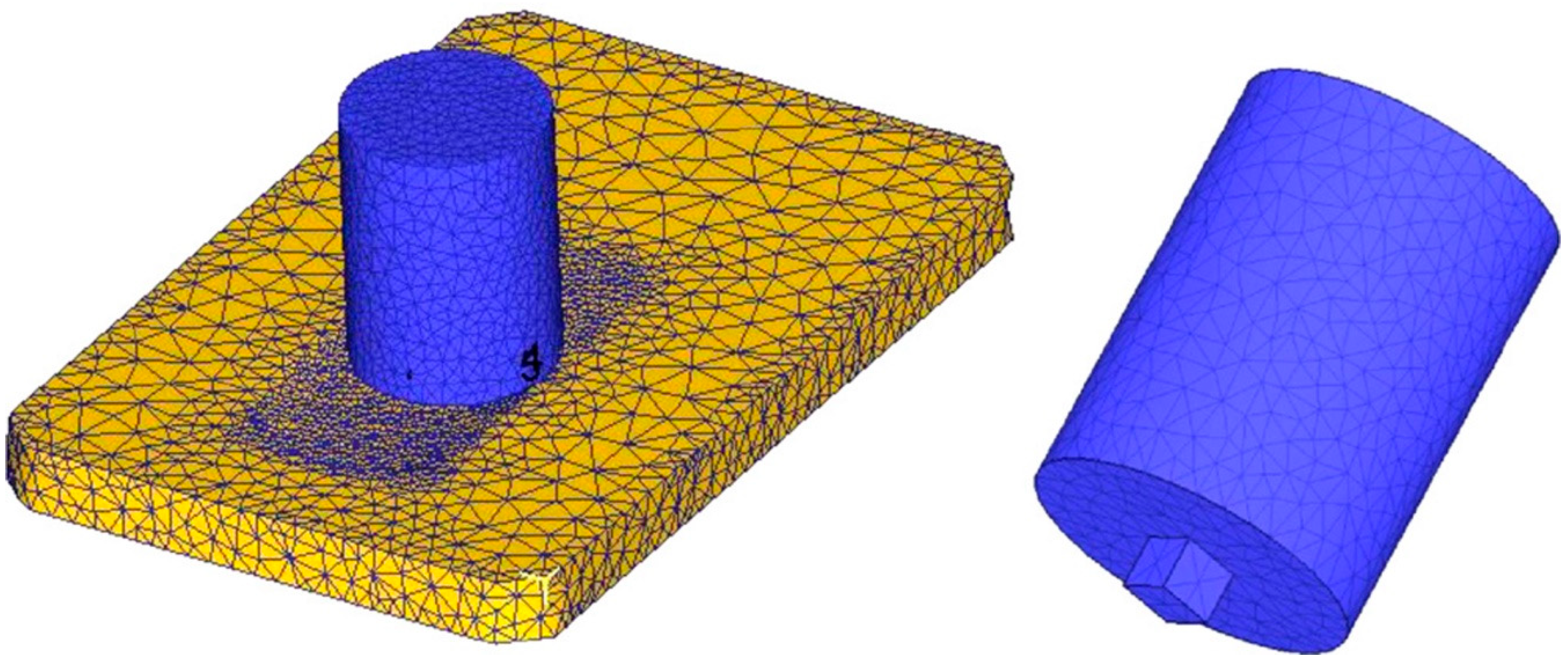
To overcome the problem of mesh distortion and simulation failure in Lagrangian approach, some researchers [89,90] employed incremental remeshing (automatic re-meshing) techniques. However, this re-meshing approach is computationally expensive. Akbari et al. [91] developed a thermo-mechanical model based on the Lagrangian approach using automatic re-meshing method. They found that about 90 percent of the heat generation was produced by the tool shoulder, while the pin contributed just 10% of the total heat generation. Moreover, most of the heat generated came from the frictional heat generation and a small amount of heat is generated due to plastic deformation. Asadi et al. [89] used the DEFORM-3D software to develop a thermomechanical model to simulate the FSP based on Lagrangian implicit and non-uniform mesh with automatic re-meshing. In their model, they assumed a rigid visco-plastic workpiece material and a rigid tool. Moreover, the friction factor and thermal properties of the tool and workpiece material were set fixed. The Arrhenius formula was utilized to correlate the flow stress with the plastic strain and temperature. A fine mesh was used around the tool and beneath the tool shoulder for accuracy, while a coarse mesh was used outside the processed zone, as shown in Figure 7. They found that the highest heat generation was produced at the top surface of the workpiece, which softened the material at this zone. Additionally, the highest peak temperature was found at the advancing side, 5 mm away from the weld center.
One of the challenges in Lagrangian modeling for FSW is the severe mesh distortion that occurs due to the large material flow around the tool. This distortion can lead to numerical instabilities and inaccuracies. This problem can be solved using the Eulerian formulation.

4.1.2. Computational Fluid Dynamics (CFD) Models

The Eulerian formulation utilizes a spatially fixed grid, as depicted in Figure 8. In this approach, the material moves relative to the stationary nodes of the non-deforming mesh. However, certain Eulerian elements might not always have any material; some might be completely or partially empty. Therefore, it is necessary to calculate the Eulerian physical boundary for every time increment, which is normally not the case with an element boundary. Because it permits material to pass through the mesh, the Eulerian formulation is appropriate for solving fluid dynamics issues. In the early 2000s, the fluid flow analysis technique known as computational fluid dynamics (CFD) was modified for FSW modeling in order to consider the plasticized material as a non-Newtonian fluid [90]. This method acknowledged that the material behaves more like a viscous fluid than a solid at the high temperatures and strain rates encountered during FSW.
To describe the non-Newtonian behavior in CFD models, the dynamic viscosity (μ) is typically defined using specific constitutive equations that link flow stress (σ), strain rate (ε˙), and temperature (T). The Sheppard and Wright model was widely used to calculate flow stress, which is then converted to viscosity via the relation μ = σ/3ε˙ [90,92]. Another common approach is the Carreau model, which is particularly effective in describing the shear-thinning behavior of the plasticized material [59]. In addition, different models such as Perzyna model [88], power law dynamic viscosity (describes the dynamic viscosity of non-Newtonian fluids as a function of shear rate) [93], and modified Bingham model of dynamic viscosity (applying a high-viscosity linear flow below the yield point) [94] were also used as dynamic viscosity models during CFD modeling of the FSW process. By utilizing these laws, CFD models can accurately capture the transition of the workpiece from a solid-like state to a viscous-flow state under extreme thermomechanical conditions.
Chen et al. [94] investigated the thermal-mechanical conditions during the FSW process utilizing a CFD model. The workpiece is assumed to be a non-Newtonian, incompressible fluid. For incompressible single-phase fluid flow, the momentum conservation equation and continuity equation are provided as follows:
ρ t + · ( ρ v ) = 0
ρ v t + · ( ρ v v ) = p + · ( μ ( v + v T ) )
where ρ , μ , p , v , and t are the density, the viscosity, the pressure, the velocity vector, and the flow time, respectively. Moreover, the equation of energy conservation is given as follows:
ρ H t +   · ( ρ v H ) =   · ( k T ) + S v
where H , T , k , and S v are the enthalpy, temperature, the thermal conductivity, and the spatial source term regarding the volumetric heat generation owing to plastic deformation, respectively. The enthalpy is given in Equation (17):
H =   T r e f T C p d T
They [94] considered the heat generation due to friction and plastic deformation in their model. The frictional shear stress and the relative velocity between the tool and the workpiece were used to calculate the facial heat flux at the tool/workpiece interface, which represents the heat generated from friction as given in Equation (18):
Q f =   η   ·   τ f   ·   v r e f
where τ f , and v r e f are frictional shear stress and the interfacial relative velocity between workpiece and tool. η is the heat fraction into the workpiece material and they considered it as 0.7. The heat produced by plastic deformation was regarded as a volumetric heat flux and was included as a source term ( S v ) in the energy conservation Equation (16). The flow stress multiplied by the rate of plastic deformation was used to compute the volumetric heat flux. The plastic deformation heat generation ( Q p ) can be computed as follows:
Q p = k ·   σ ·   ε ˙
where k is the fraction of plastic deformation converted into heat, σ is the flow stress, and ε ˙ is the strain rate.
Subrata and Phaniraj [95] studied the temperature distribution on the workpiece and tool materials during the FSW of SS304 steel using a CFD model. They assumed the pin is cylindrical, the contact condition at the tool-workpiece interface is partial sticking condition, and the workpiece is modeled as a non-Newtonian incompressible viscoplastic flow. The model was solved utilizing the CFD solver FLUENT. They found that compared to behind the tool, heat transfers quickly because of the high temperature gradient in front of the tool. Over the tool surfaces, the temperature is high close to the tool-workpiece interface. In the first two centimeters above the workpiece, the tool’s temperature gradient is comparatively high. In contrast to the workpiece’s elliptic temperature contours, the temperature contours are round because there was no heat generation in the tool due to material flow.
Hasan [96] utilized ANSYS FLUENT-CFD code to construct a CFD model to simulate the FSW of AZ31 magnesium alloy. They validated their model using the estimated temperature with experimental results from the literature with 11% differences. In the same context, Tiwari et al. [50] used a steady-state Eulerian formulation to study the material and heat transfer model during the FSW process of DH36 steel. The workpiece material was regarded as a non-Newtonian viscoplastic fluid, with temperature and flow stress influencing viscosity. The findings demonstrated that the highest temperature varied with thickness and was measured at the contact interface between the welded material and the tool shoulder.
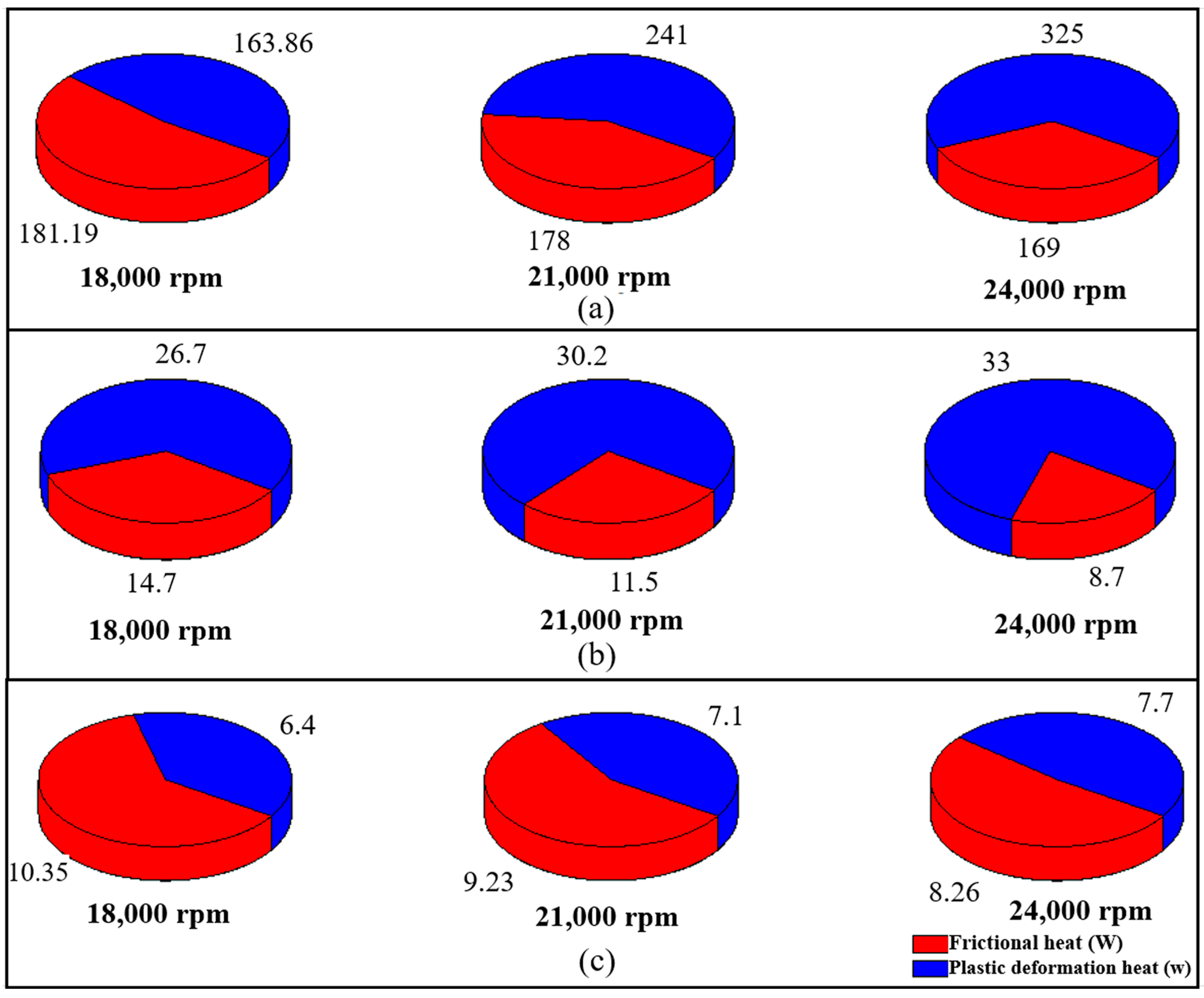
It is important to note that the assumption of neglecting plastic heat generation is only valid for conventional FSW parameters at relatively low tool rotation rates. At such speeds, many researchers have reported that the plastic heat generated is no more than 4.4% of the total heat generation [64,95,97]. However, at ultra-high rotational speeds, Mohan et al. [49] used the CFD to study the material flow, heat generation, and temperature distribution in the SZ during FSW of AA1100 aluminum alloy and found that plastic heat becomes the dominant heat source. The researchers included boundary conditions to take into consideration the potential for partial melting at high rotating speeds, assuming a partial sliding–sticking contact condition at the tool-workpiece interface. They investigated and found that the partial melting did not occur and that plastic heat generation at high rotating speeds had a greater influence on heat generation than frictional heat generation, as shown in Figure 9. Plastic deformation accounts for 48.84% of the total heat generated at 18,000 rpm, while it increased to 58.02% and 66.21% at 21,000 and 24,000 rpm, respectively. Moreover, while the contribution of the pin side and pin tip to the overall heat generation decreased as the tool rotation rate increased, the shoulder’s contribution increased.
Kumar and Sinha [98] investigated the heat generation during FSW of AA2024-T4 aluminum alloy utilizing a CFD model. They found that the heat flux was almost symmetrical about the axis of the tool, and as the tool’s rotation rate increased, so did its magnitude. Moreover, the tool shoulder produced about 85% to 90% of the total generated heat. In the same manner, Chen et al. [99] used ANSYS Fluent to simulate the FSW of AA6061 aluminum alloys utilizing the CFD approach. They found that the heat flux distribution was nearly symmetric with respect to the tool axis. Sun et al. [100] used a novel approach brought forward to compute the interfacial friction stress directly from the yield criterion, eliminating the need to first ascertain the friction factor. The relationship between temperature and interfacial friction stress is explained. The researchers validated the CFD model’s results in terms of temperature with the experimental results and reported the satisfactory agreement between both results.
On the other hand, the CFD technique was utilized to predict the heat generation and material flow during dissimilar FSW. Kadian and Biswas [101] developed a novel model based on the volume of fluid (VOF) approach to study the dissimilar FSW of AA6061 aluminum and Cu-B370 copper plates. It is discovered that the advancing and retarding sides experience different temperature variations. Compared to the aluminum side, the copper side dissipates heat far more quickly. As a result, the copper side’s isotherm contours are substantially greater than the aluminum sides. On the other hand, the highest temperature readings are found directly beneath the pin tip. The dissimilar FSW of aluminum to steel was investigated by Bokov et al. [102]. They used a CFD model to study the effect of the tool pin shape on the temperature distribution. According to the simulation results, a bigger tapered pin angle resulted in more mechanical effort on the joint line and a larger SZ was formed. Moreover, about 26% of the total heat generated by the tapered pin tool was generated by the pin. In contrast, the pin’s overall heat generated in the case of the cylindrical pin profile was close to 15% of the total heat generated. Zhang et al. [103] utilized the CFD and VOF methods to investigate the dissimilar FSW of 2024-T4 aluminum alloy to TC4 titanium alloy. The combined material’s thermo-physical properties at the SZ have been treated as a functionally graded material (FGM). They found that the tool shoulder produces most of the generated heat, while a small amount of heat generation was generated by the tool pin. Because of the significant difference in the thermophysical characteristics of titanium and aluminum alloys, a severe asymmetric temperature distribution has been observed during aluminum-titanium dissimilar FSW [103].
For the investigation of FSW, the CFD models have several benefits. Without the need for expensive experiments, they offer in-depth insights into intricate thermo-fluid phenomena such as material movement, heat generation, and temperature distribution, allowing for process optimization along with understanding of the FSW process physics. Nevertheless, it is still difficult to accurately depict the intricate interactions between the tool and workpiece, material flow, and extreme plastic deformation. Prediction accuracy may be impacted by uncertainty introduced by material constitutive models and turbulence modeling in extreme conditions.

4.1.3. Arbitrary Lagrangian-Eulerian (ALE) Models

The FSW process is frequently numerically simulated using the flexible Arbitrary Lagrangian–Eulerian (ALE) approach. By enabling mesh motion independent of material flow (Eulerian) and tracking material deformation (Lagrangian), it combines the advantages of both Eulerian and Lagrangian techniques [104]. In FSW simulations, where there is significant material deformation, intricate thermo-mechanical interactions, and tool-workpiece interactions, this hybrid capability is especially beneficial. As a key component of the adaptive meshing capabilities, the mesh is periodically smoothed to reduce element distortion and maintain advantageous aspect ratios of elements while maintaining the same mesh topology. Both the quantity of nodes and components and their connectivity are unchanged. It can be used to examine both Eulerian and Lagrangian problems [105].
Assidi et al. [78] utilized the ALE approach to study the FSW of 6061 aluminum sheets. The model was implemented in the Forge3 V7.0 software. Their preliminary study employed Norton’s friction model and demonstrated the high sensitivity of welding forces and tool temperature estimated by friction coefficients, the necessity of accounting for changes to the contact surface caused by slight friction variations, the potential for highly accurate force calibration, and the challenge of accurately presenting the tool temperature profile. However, using Coulomb’s friction model enables the calibration of a friction coefficient that provides good agreement with experiments on forces as much as tool temperatures for a range of welding speeds, as well as the acquisition of realistic temperature profiles.
Meyghani et al. [106] created a three-dimensional finite element analysis of FSW using the ALE method, which included examining the thermal behavior and temperature progression of the alloy AA-6061-T6. The model was solved utilizing ABAQUS 6.14 software. They found that a significant amount of heat was produced by the shoulder, according to the results of the workpiece cross-section taken at various rotational speed ratios. Moreover, the heat generation increased by increasing the tool rotation rate and/or decreasing the welding speed.
A kinematic framework was developed by Dialami et al. [107] based on the combination of ALE, Eulerian and Lagrangian for different parts during FSW process modeling. This permits the convenient application of the boundary conditions and the treatment of arbitrary pin geometries. For the ALE portion of the domain, a mesh-moving approach made coupling with the remaining sub-domains (the Eulerian and Lagrangian ones). The heat produced by friction and plastic dissipation is taken into consideration. The impact of boundary conditions that are both stick and slip is examined. Because of the pin’s rotational and linear motion as well as the asymmetry of heat generation surrounding its surface, the results show asymmetry of the temperature profiles surrounding the pin.
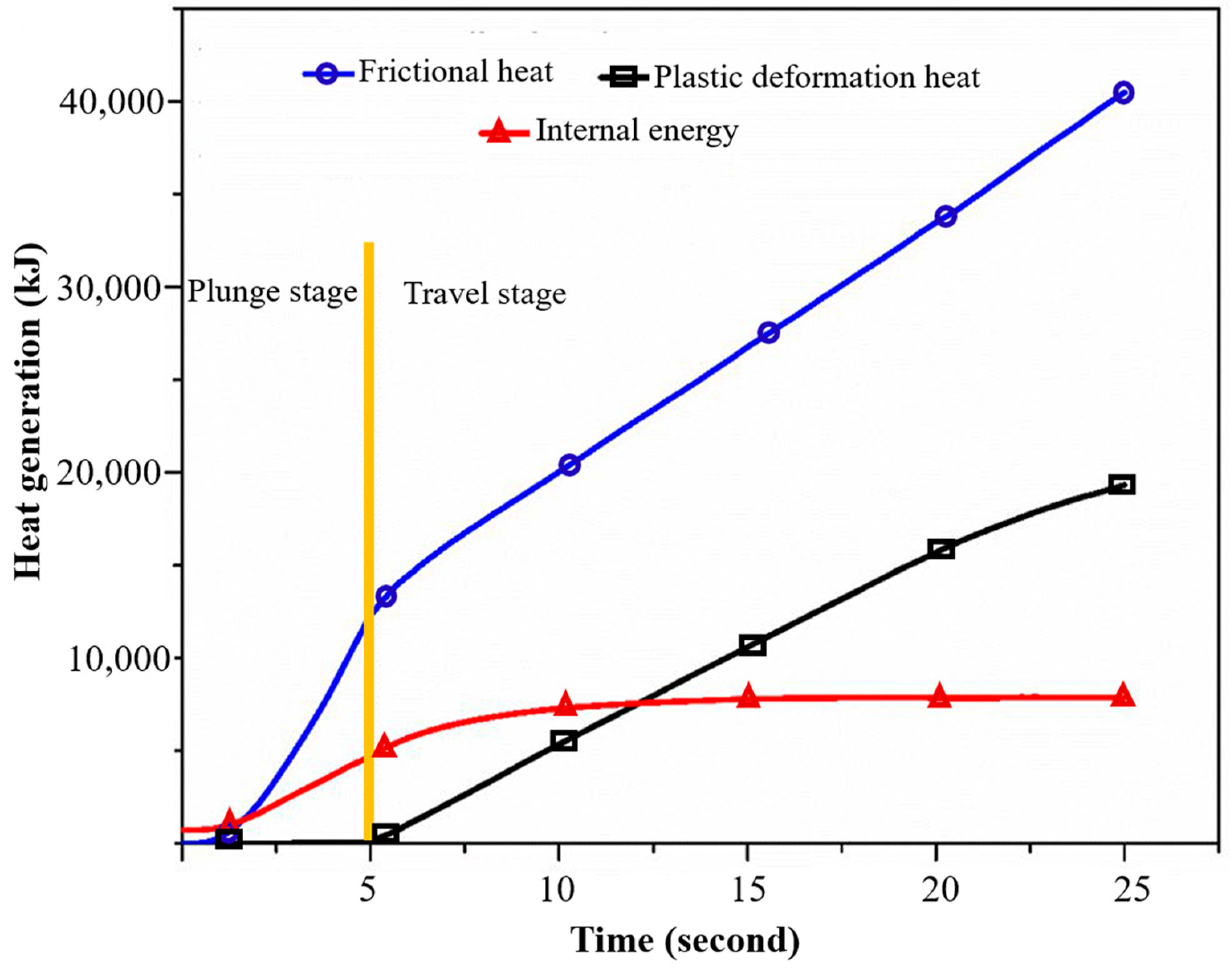
The difference between the heat generated due to friction and plastic deformation was studied by Myung et al. [105] utilizing an ALE model. They used the Johnson-Cook material model to simulate the flow stress as a function of temperature and strain rate. Moreover, the workpiece’s thermal properties were considered as temperature-dependent properties. They found that frictional dissipation produced the majority of the heat during the plunging stage, while combined plastic and frictional dissipation produced the majority of the heat during the travel stage, as shown in Figure 10. The heat transmission between the sheet and the backing plate, as well as between the sheet and air, caused the internal heat energy to eventually reach saturation during the travel stage. It was demonstrated that friction generated more heat than plastic dissipation. However, the rate of heat generated by friction in the travel stage was only twice the rate of plastic dissipation.
Although ALE reduces mesh distortion and provides a useful compromise for FSW simulation, it has significant disadvantages. It is a demanding approach due to its high computational cost, complexity of implementation, mesh management and remapping errors, intricacy of material flow, and handling of severe thermo-mechanical contact. The decision to employ ALE for FSW frequently entails balancing the algorithm’s substantial computational load, complexity, and potential for numerical errors against its capacity to manage deformation.

4.1.4. Coupled Eulerian Lagrangian (CEL) Approach

In a different way to the ALE method, the Coupled Eulerian-Lagrangian (CEL) description is another hybrid approach that blends Eulerian and Lagrangian formulations. Regions with large material flow and deformation, like the workpiece in FSW, are modeled in the Eulerian domain of the CEL formulation, whereas regions with relatively small deformations, like the tool, are modeled in the Lagrangian domain [22]. Specialized contact algorithms that take into account the interaction between the Eulerian material and the Lagrangian bodies are used to handle the coupling between the two domains. This method preserves accurate tool geometry and motion representation while enabling effective simulation of processes involving extreme deformations [108]. A penalty-based contact algorithm is used to manage the tool-workpiece interaction, calculating frictional forces and heat generation while enforcing the no-penetration condition. The tool’s geometry and motion are accurately represented by the Lagrangian formulation, while the workpiece’s Eulerian formulation enables effective simulation of the steady-state phase of FSW [109]. Furthermore, CEL models can effectively estimate the welding defects during the FSW of similar and dissimilar materials [110].
Accurately representing the tool’s geometry and motion while permitting significant material deformation in the workpiece is one benefit of the CEL approach [111]. Frictional heating, a crucial part of heat generation in FSW, can now be calculated more precisely. Furthermore, the steady-state phase of FSW, in which material flows continuously through a control volume surrounding the tool, can be effectively simulated due to the Eulerian formulation for the workpiece.
Mirabzadeh et al. [112] utilized the response surface method (RSM) and CEL model to investigate the effect of the different welding parameters on the heat generation during the FSW process. The simulated results in terms of temperature were compared to the experimentally measured temperatures with 6% error. They reported that about 70% of the heat generated was influenced by the tool rotation rate. Additionally, the tool geometry, welding speed, and tool tilt angle affected the heat generation during the process by 15%, 11%, and 4%, respectively.
Malik et al. [113] proposed a 3-D finite element model based on the CEL technique in a commercial Abaqus/Explicit code to investigate the effect of the different pin profiles on the FSW of aluminum alloy. They also used the Johnson-Cook model to describe the material flow stress and Coulomb’s friction law for the friction heat generation. They investigated that compared to the frustum pins, the peak temperatures estimated for straight pins were noticeably greater. In both the Frustum and Straight pins, triangular pins generated the least amount of heat. Additionally, increasing the number of pin sides, i.e., square and pentagon pins, led to an increase in the peak temperature. However, the peak temperature decreased again at the hexagonal pin.
In a similar manner, Akbari and Asadi [114] developed a thermo-mechanical model using the CEL approach to study the effect of the triflute pin shape on the FSW of 6061 aluminum alloy. The study included a cylindrical pin and three triflute pin shapes with 1, 1.5, and 2 triflute radii. They found that in the deeper flutes, the tool-workpiece contact surface area increased to somewhat counterbalance this increased temperature requirement. However, a higher tool rotation speed is required for defect-free joint production, which could negatively impact the tool’s lifespan and the mechanical characteristics of the joint. When it comes to improving material flow and attaining flawless welding, flutes with a smaller radius were far more effective than those with a bigger radius. Choudhary and Jain [115] investigated the effect of tool pin eccentricity on the heat generation and defect formation during FSW of AA2024 aluminum alloy. They concluded that increasing pin eccentricity from 0 to 0.2 mm and the tool tilt angle from 0 to 2° resulted in decreasing the defect size and increasing the heat generation.

4.1.5. Smoothed Particle Hydrodynamics (SPH)

SPH is a mesh-free, particle-based computational technique that discretizes the continuum into a collection of particles with field variables (stress, temperature, velocity, and mass). Using kernel functions over a smoothing length, values are interpolated at particle locations to solve the governing equations (conservation of mass, momentum, and energy) [116]. The natural handling of large deformations due to the particles’ movement with the material and the avoidance of mesh distortion problems that are common in FEA are two important benefits of FSW modeling. Furthermore, Lagrangian nature makes it possible to directly visualize the material flow surrounding the tool. Furthermore, no special algorithms are needed for surfaces or interfaces. Because of these characteristics, SPH is especially well suited to simulate the complicated material flow, stirring action, and extreme plastic deformation that occur in FSW.
Tartakovsky et al. [117] proposed an SPH to estimate the effect of the tool geometry and welding parameters on the heat generation in FSW. Weld metal is treated by the model as a non-Newtonian fluid with a viscosity that varies with temperature. The heat generation at the tool/material interface and the contribution of this surface heating were determined by combining the momentum conservation equation’s viscous and particle interaction forces. They reported that as the tool’s rotational rate increased, more heat was produced and the temperature surrounding the tool surface also increased. The temperature profile behind the tool has a longer tail as a result of the increase in welding speed, although peak temperatures close to the tool surface didn’t remarkably increase. Additionally, the two flat sides and smooth cylindrical tool pin produced the same average temperature around the tool pin.
Pan et al. [118] presented a Lagrangian model based on the SPH technique to investigate the FSW of magnesium alloys. They reported that the stirring zone’s temperature decreased with increasing welding speed. Furthermore, raising the rotational speed in the stirring zone resulted in greater temperatures and increased heat generation due to the higher strain rate and plastic dissipation. In a similar manner, Ansari and Behnagh [119] developed an SPH model to study the dissipation energy, force, and plastic strain during the plunge stage in the FSW process. Their model has been validated using the estimated tool plunge force against the experimental measured one. They investigated that frictional energy constitutes the majority of the process’s overall energy, accounting for between 80 and 90%. The fast rotational speed and axial pressure of the FSW tool on the work-piece surface are the causes of the high percentage contribution of frictional energy relative to plastic energy [119].
Meyghani et al. [120] utilized the ALE and SPH approaches to investigate the heat generation and temperature distribution during FSW of 6061-T6 aluminum alloy. They found that the temperature distribution beneath the shoulder was asymmetric. Additionally, they noted that the welding rotational rate has a greater impact on the peak temperature than the welding speed. This problem has been raised because rotating speed has a greater impact on frictional heat generation than transverse velocity. Because of the reduction in heat accumulation, the peak temperature decreased as the welding speed increased when the rotating speed remained constant.
The FSP of AZ91 magnesium alloy was investigated using the SPH method by Roshan et al. [121]. The correctness of their SPH model is confirmed by the strong agreement between the simulated and observed temperatures across FSP phases, with errors below ~5% along the shoulder perimeter 10 mm from the SZ center. The SZ reached a peak temperature of about 83% of the base material’s melting point. Moreover, applying a tool tilt angle of 2° resulted in a defect-free processed zone due to the high compressive stress and frictional heat generation in the trailing side of the welding tool. Roshan et al. used the SPH method to investigate the FSW and stationary shoulder FSW of AA6061 aluminum alloy. They showed that SSFSW produced lower heat generation and plastic strain in the SZ compared to FSW. They also noted that SPH can give a deeper understanding of the temperature flow and material flow in the SZ during the conventional FSW and SSFSW processes.

4.2. Comparison and Researchers’ Interest in Different Model Techniques

From above literature, it is clear that each approach has advantages and limitations. ALE is frequently regarded as the “standard” for solid mechanics FSW since it effectively connects mechanical and thermal fields, making it possible to calculate residual stresses, which is difficult to predict using CEL and/or CFD methods. When severe plastic deformation and volumetric defects occur in the simulation, where an ALE mesh would collapse, CEL is recommended. CEL is also used to simulate the complex tool geometry. Instead of focusing on structural integrity, CFD is mainly used to comprehend the physics of the flow, such as how the material moves around the pin. SPH is becoming steadily popular for modeling defects (such as voids or tunneling defects) because it naturally permits material separation without the intricate erosion criteria required in mesh-based methods. Table 2 gave a detailed comparison between the different approaches used to modeling the FSW process.
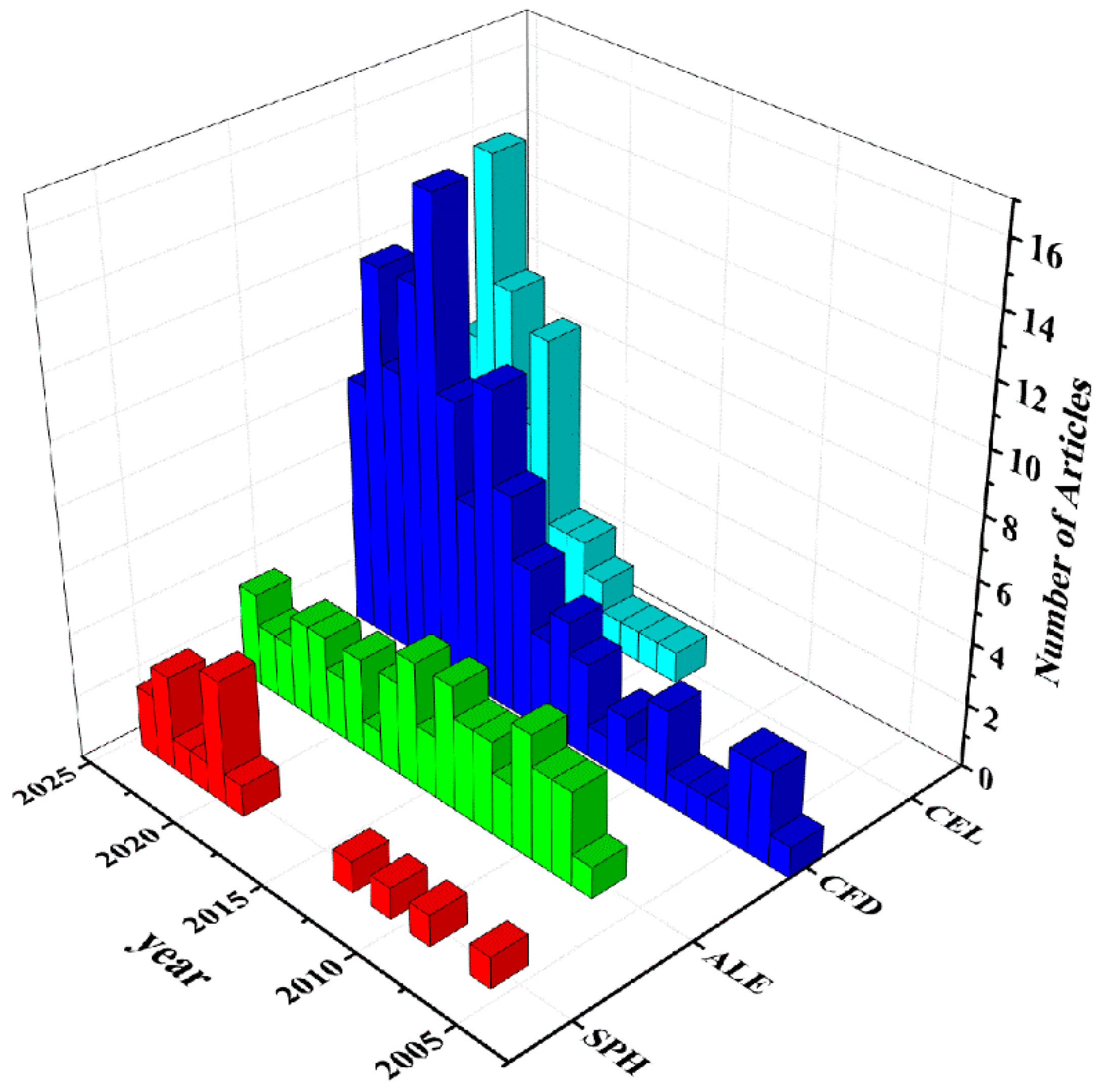
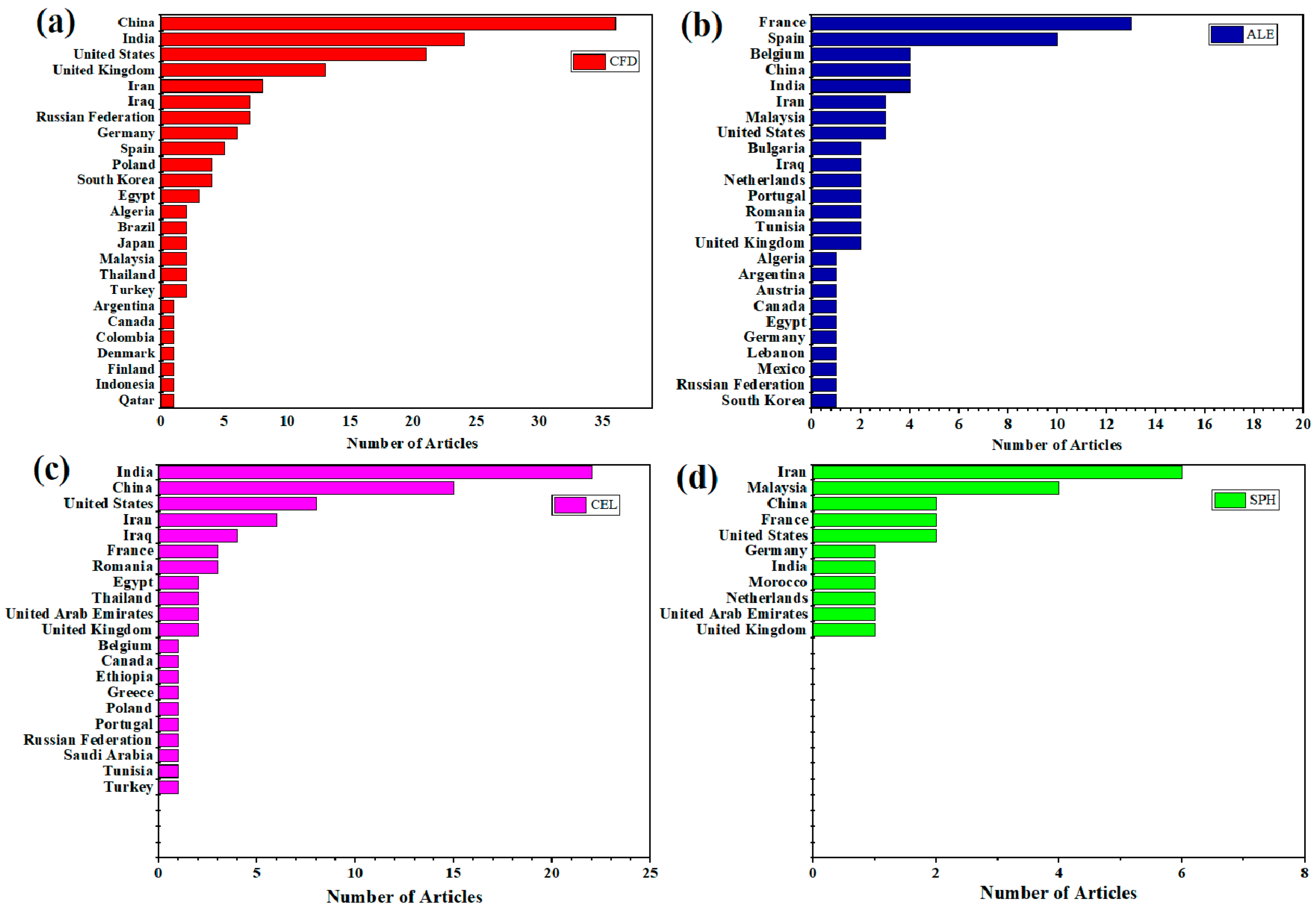
As explained in Section 2, the strong correlated to heat generated measurements during the FSW process articles were then divided according to each measurement method. Figure 11 illustrates the increasing number of FEM studies over the last 25 years. The SPH models for simulating FSW started in 2006 and showed very little of researchers’ interest. These findings may be attributed to the high computational cost of the SPH model, which requires millions of particles. The numbers of ALE models for FSW are higher than the SPH ones. However, the researchers’ interest didn’t increase over time. Despite the high accuracy of predicting heat generation during FSW, ALE is still computationally expensive and complex in terms of mesh motion and the choice of suitable mesh velocity. The figure shows the great interest of researchers in the CFD and CEL models. In spite of the assumption of isotropic material behavior, CFD models showed high accuracy in material flow and efficiency in the parametric study of FSW. For CEL models, the ability to handle problems such as complex tool geometry, extreme deformation, and solid-liquid interactions makes the CEL technique the most suitable and accurate method to simulate the FSW process. In terms of countries, Figure 12 shows the interest of researchers from various countries in different simulation approaches. Countries such as India, China, and the United States of America gave great importance to the CFD and CEL models for FSW. The ALE method finds its importance with researchers from France and Spain.
From an industrial perspective, the selection of an appropriate modeling approach depends largely on the specific application requirements. For routine process optimization and parametric studies, CFD models offer an effective balance between accuracy and computational cost, making them suitable for industrial-scale implementation. In contrast, for high-value components where defect prediction and residual stress analysis are critical, CEL and ALE models are more appropriate, despite their higher computational demands. The increasing use of hybrid approaches and machine learning techniques is expected to further enhance the scalability of these models, enabling their broader adoption in manufacturing environments.

4.3. Future Work in FSW FEM

The future of numerical simulation in FSW is poised for significant advancements, driven by the need for higher accuracy, efficiency, and predictive capabilities. Key research directions include:
  • Using machine learning (ML) to overcome the drawbacks of Johnson-Cook or Arrhenius-type material models and create temperature/strain-rate-dependent flow stress models from limited experimental data. Furthermore, modeling intricate interfaces (such as those between Al-Ti and Al-Steel) with precise residual stress analysis and intermetallic layer growth prediction.
  • Improving the computational cost using GPU/parallel computing and developing surrogate models such as neural networks for real-time process simulation.
  • Combining the solid mechanics models with CFD for better prediction of material flow, heat generation, defects, and tool wear.
  • Modeling the FSW process of non-metallic materials such as polymers and composites with anisotropic behavior.
  • Improving special FSW modules and enhancing the capabilities of the Ansys, Abaqus, and COMSOL software for FSW simulations

5. Experimental Measurements of Heat Generation

Even though numerical and analytical models are extremely helpful for predicting FSW thermal fields, they need to be carefully validated by experimentation. For the development of in-process monitoring, precise experimental measurement of heat generation also offers process understanding, optimization of process parameters, and quality control [122]. However, experimental measurement of the heat generation during FSW is challenging because of the harsh environment due to the rotating tool, high temperature, and severe plastic deformation. Researchers have used a variety of creative techniques over the last 25 years, namely thermocouple embedding, infrared thermography, and calorimetry, to investigate the extreme heat environment in the FSW zone.
The most used temperature sensors in FSW are thermocouples because of their direct measurement ability, broad temperature range, resilience, and affordability. According to the Seebeck effect, thermocouples produce a voltage proportionate to the temperature differential between two dissimilar metal wires (junctions). It is possible to determine the local temperature by positioning one connection (the measuring junction) at the point of interest and the other (the reference junction) at a known temperature [123]. In order to respond to welding disturbances more quickly, the thermocouple is typically positioned as close to the plastically deformed region, as possible through a drilled hole in the workpiece and/or tool [124,125]. However, the integration of thermocouples poses significant experimental challenges. If positioned too close to the tool’s path, the sensors are highly susceptible to mechanical shearing due to the severe plastic deformation and intense stirring action. Furthermore, the presence of drilled holes and the sensors themselves can potentially disrupt the local material flow, leading to slight deviations from the actual welding conditions. Consequently, researchers typically strategically embed thermocouples at specific offset distances from the SZ to ensure sensor survival and maintain the integrity of the material flow while still capturing relevant thermal data [12].
Early, thorough thermocouple data from Chao and Qi on 304L stainless steel revealed a nearly linear rise in peak temperature with the tool rotation rate. Frigaard et al. [57] revealed that peak temperatures for AA6082-T6 were between 480 and 520 °C, and that they were highly influenced by traverse welding speed and rotation rate. Sara et al. [126] utilized thermocouples located at 15, 20, and 25 mm away from the weld centerline to investigate the FSW of AA5052 aluminum alloy. They reported a good agreement between the experimental and estimated temperature at all the tool welding parameters when using a coefficient of friction between 0.64 and 0.95.
Raturi and Bhattacharya [127] used thermocouples located in different locations on the workpiece top surface and inside it to investigate the temperature variation during the FSW of AA6063-T6 and AA7075-T651 dissimilar aluminum alloys. They used two different tool geometries: threaded with intermittent flat faces (TIF) and plain cylindrical (CYL). They reported that the TIF pin profile’s capacity to increase the degree of plastic deformation with the aid of intermittent flat faces caused the temperature to rise during dissimilar FSW considerably more quickly than the CYL pin. Moreover, there is an asymmetry with a larger temperature at the trailing side of the tool traverse than the leading side because the peak temperature at any point along the weld line reaches post tool leave practically with a consistent delay [127].
Infrared (IR) thermography is another way to determine the surface temperature distribution during FSW. IR uses the infrared light that an item emits to measure surface temperature distributions without making contact. Infrared radiation is emitted by anything above absolute zero. The emissivity (ε) and surface temperature of the item determine the radiation’s intensity and spectrum dispersion. This radiation is detected by an infrared camera, which then transforms it into an electrical signal and creates a 2D temperature map (thermogram) of the surface using calibration and the object’s emissivity information.
Raikoty et al. [128] studied the surface temperature distribution during the FSW of 6061-T6 aluminum alloy at a high tool rotation rate of 15,000 rpm using an infrared camera. They reported that a sound weld requires a minimum tool translational velocity of 125 mm/min to reach a maximum temperature of about 580 °C, which is slightly below the alloy’s solidus temperature. A new hybrid vision approach for online FSW process monitoring, which involves taking a weld image using a thermal imaging camera and a visual band camera, was proposed by Mężyk and Kowieski [129]. The new approach can not only measure the surface temperature distribution but also allow detection of subsurface defects. Despite the non-contact measurements, IR can be used only for surface measurements. Additionally, inaccurate values of emissivity led to significant temperature errors. To mitigate this, a common laboratory practice involves coating the workpiece surface with a thin layer of high-emissivity (ε > 0.9) matte black paint. This treatment standardizes the surface emissivity and minimizes measurement errors [130]. However, repeatability of temperature measurements is generally acceptable for thermocouples under controlled conditions but can vary significantly for IR thermography due to surface condition changes between experiments.
Using the calorimetric approach, which measures temperature variations in the water around the weld region, heat input can be calculated using mass and specific heat capacity. Sato et al. [131] examined the amount of heat generated when aluminum alloy 5083 was friction stir welded (FSW). The authors used multiple regression analysis to develop an empirical equation that links heat input to input factors, specifically travel speed, rotational speed, and shoulder diameter, after measuring heat inputs across a range of welding parameters using the calorimetry method. The experimental results showed a significant relationship between the heat input and the grain size in the SZ, which offers guidance for improving the welding procedure. Moreover, the heat input increased by increasing the tool rotation and decreasing the welding speed. Furthermore, a larger shoulder diameter resulted in higher heat input.
In a similar manner, Yi et al. [132] examined the use of the calorimetric method to assess heat input during the FSW of 1100 and 5083 aluminum alloys. They found that, at the same welding parameters, the heat input during FSW of 1100 alloy was higher than that in 5083 alloy due to the higher thermal conductivity of the 1100 alloy. Furthermore, they used a large number of experimental results and multi-regression analysis to derive an empirical formula to compute the heat input during the FSW process as follows:
H I = 7.2   V 0.8   N 0.1   D 0.55   d 0.45   h 0.3   λ 0.4
where H I is the heat input in J/mm, V is the welding speed in mm/s, N is the tool rotation rate in rad/s, D is the tool shoulder diameter in mm, d is the tool pin diameter in mm, h is the pin height, and λ is the workpiece material’s thermal conductivity in W/m.K. The calorimetry technique is a good method to determine the total heat input during FSW. However, it lacks the spatial resolution required to capture localized thermal gradients. Consequently, it cannot be used to analyze phenomena that depend on local temperature variations, such as microstructural evolution or the formation of specific volumetric defects like tunneling.
Some researchers [133,134] utilized the FSW parameters and tool torque to compute the heat input during the process, as calculated from Equation (21):
H I   ( J / m m ) =   P o w e r s p e e d =   η ω T v
where ω , T , v , and η are the tool rotation rate in rpm, tool torque in N.m, welding speed in mm/min, and heat transfer efficiency, respectively. Ahmed et al. [134] used Equation (21) to determine the heat input during dissimilar FSW of AA5083, AA5754, and AA7020 aluminum alloys. They investigated the importance of controlling the heat input to produce a sound weld. The findings indicate that lower heat input during FSW leads to sound joints, while increased heat input results in defects, such as tunnel formations. Additionally, at a specific tool geometry and plunge depth, the maximum temperature is mostly determined by the rotation tool speed, whereas the heating rate is determined by the welding speed. Furthermore, changing the alloy in the advancing side has no remarkable effect on the heat input. Finally, they concluded that at a specific tool geometry and plunge depth, the maximum temperature is mostly determined by the rotation rate, whereas the heating rate is determined by the welding speed.
Rathinasuriyan et al. [135] examined the heat generation that results from applying conventional FSW and Submerged Friction Stir Welding (SFSW) to the 6061-T6 aluminum alloy, highlighting the importance of torque as a key determinant of the welding process. They used the machine data, such as plunge force and tool torque, the welding parameters, and the calculated coefficient of friction to determine the heat input. The results showed that higher rotational rates were associated with higher heat generation and that SFSW required higher torque and power, especially at greater water head, which led to more significant heat generation. Furthermore, a higher water head was found to result in higher torque needs and power consumption.
Heat generation in FSW is still difficult to measure experimentally, despite significant advancements. To evaluate findings and direct future research, it is essential to comprehend these constraints. Thermocouples disrupt the process but give direct internal data. Although IR is non-contact, it only views the surface and has emissivity issues. In IR thermography for metals, emissivity uncertainty is the main cause of mistakes. It is very challenging to determine emissivity accurately and in real time when surface conditions are dynamic and non-uniform. Calorimetry measures total heat generation but lacks spatial details. Lastly, it is frequently impractical to adapt advanced measurement methods (such as complex calorimeters, high-speed infrared, and dense thermocouple arrays) to large-scale industrial FSW activities. Table 3 compared the different experimental methods in terms of spatial resolution, response time, calibration, and uncertainty.

Future Directions for Experimental Measurements

  • Dual-Wavelength IR can reduce emissivity dependence and improve accuracy, while high-speed or high-resolution IR can be used to capture finer spatial details and faster transients.
  • To reduce disruption and enhance spatial resolution, smaller, less intrusive thermocouples (such as thin-film thermocouples deposited on the tool or workpiece surface or micro-welded junctions) are the best choice.
  • To give a more comprehensive experimental image, calorimetry (for total heat), synchronized infrared thermography (for geographical distribution), and embedded thermocouples (for internal validation) can be combined.
  • applying advanced machine learning methods, inverse modeling, and signal processing to intricate thermal datasets to gather additional information regarding defect formation recognition, material flow patterns, and heat source properties.

6. Effect of Heat Generation on Microstructure Evolution

Through its effects on peak temperature, cooling rate, and deformation mechanisms, heat generation in FSW controls the evolution of microstructural characteristics [136]. In the SZ, optimal heat input refines grains via DRX, whereas in the HAZ, too much heat coarsens grains or dissolves precipitates. Advanced procedures (active cooling, hybrid processes), tool design, and process parameters (tool rotation rate, welding speed, plunge force and depth, etc.) allow for microstructure modification. While too much heat results in abnormal grain growth or liquation, too little heat input results in inadequate material flow [13].
The severe thermomechanical history that the material undergoes during welding, particularly in the SZ generates a deep modification of the microstructure. Therefore, the SZ undergoes full recrystallization (the formation of refined, equiaxed, and homogenous grains), while the precipitate dissolves and coarsens inside and around the stirred zone [137,138]. However, the modification of the microstructure of the stirred domain is most likely caused by the tool’s geometry as well as the sophistication of the material flow during the stirring process.
Rouzbehani et al. [139] investigated the effect of using different tool rotation rates and welding speeds on the microstructure evolution during FSW and underwater FSW (UFSW) of Al7075 aluminum alloy. They reported that as the welding speed increased from 25 to 300 mm/min, i.e., decreasing the heat input and shortening the residence time, the average grain sizes of the welds decreased from roughly 9 to 3 μm and from 3 to 1 μm in the FSW and UFSW welds, respectively. Moreover, as the tool rotational rate increased during UFSW compared to FSW, the distribution and volume fraction of the precipitates became significantly more uniform. They attributed this effect to the lower peak temperature in the UFSW condition.
In a similar work by Ghetiya and Patel [140], the effect of the welding speed on the microstructure in FSW and UFSW of AA2024-T6 aluminum alloy has been investigated. They found that increasing the welding speed decreased the heat input, which in turn reduced the dissolution of strengthening precipitates. Furthermore, it was discovered that as welding speed increased, grain size decreased because low heat was input during both FSW and UFSW processes. However, the dissolution during the UFSW process was lower than the FSW one because of the low peak temperature and residence time, which in turn enhanced the mechanical properties.
Liu et al. [141] studied the effect of welding speed on the grain size evolution in FSW of AA2219 aluminum alloy. They found that the grain size first increased between 50 and 150 mm/min, after which it decreased to a relatively low value at 200 mm/min. They attributed this decrease to the combined effects of material deformation and heat input during FSW. Both the amount of material deformation and the amount of heat input during FSW decreased as welding speed increased. The recrystallized grain size often increases when the degree of material deformation decreases, whereas the grain refinement typically occurs when the heat input decreases. Thus, whether factor is dominant determines how grain size changes with welding speed. Kim et al. [138] reported a decrease in the peak temperature in the SZ as the welding speed increased. They also reported that the percentage of recrystallized grains increased with the welding speed. They attributed these microstructural features to the fact that the inactive annihilation of dislocations at a higher welding speed creates more nucleation sites, which results in fine and equiaxial grains in the SZ.
The tool rotation rate has a great effect on the heat input and hence on the microstructure evolution during the FSW process. The heat input was dramatically increased by increasing the tool rotation rate and decreasing the welding speed during FSW of 1100 and 5083 aluminum alloys [132]. The authors investigated that the grain size was significantly increased by increasing the heat input. The high tool rotation rate FSW of 6061-T6 thin aluminum plates was investigated by Liu et al. [142]. They reported that the peak temperature in the SZ was considerably raised by raising the rotating rate and lowering the welding speed. Significant plastic deformation and high heat input led to dynamic recrystallization, forming equiaxed grains in SZ. At fast transverse speed (1500 mm/min), the size of the precipitates Mg2Si and Al8Fe2Si in the SZ was smaller compared to low welding speed (300 mm/min) under high rotational rate. Additionally, the size of the precipitate increased with the increase in rotational rate from 8000 to 10,000 rpm. The authors said that the precipitates were dissolved during the heating stage and then regenerated during the cooling stage. Thus, the faster welding speed and/or higher tool rotation rate resulted in loner residence time and/or higher peak temperature, which increased the precipitates size and number [142]. The authors then choose the best condition (8000 rpm and 150 mm/min) to study the effect of using different backing plate materials (steel and copper) [143]. They found that the dissolution and coarsening of Mg2Si, Al8Fe2Si, and Al2CuMg precipitates led to a broad softening zone. Nevertheless, the SZ produced using the steel backing plate had more precipitates than the copper backing plate, which further enhanced the joint’s tensile strength and microhardness. On the other hand, Mehri et al. [144] investigated the FSW of 7075-T6 thin aluminum sheets at low tool rotation rates (600, 1000, and 1600 rpm). They found that in FSW of a thin sheet, the heat input has a minimal impact on the microstructure evolution, even though the dominant parameter was plastic strain.
Rathinasuriyan et al. [145] studied the effect of tool rotation rate and welding speed on the weld geometry and distortion angle during FSW of AA2024 and AA7075 aluminum alloys. They investigated that due to increased heat output, higher rotational speeds produced larger weld geometries, including wider bead widths and deeper penetrations. Moreover, at lower welding speeds, angular distortion was more noticeable.
Jabraeili et al. [146] studied the FSW of an AA2024 aluminum to 304 stainless steel dissimilar joint. They found that the ideal conditions were reached with a zero-tool offset, a welding speed of 65 mm/min, and a tool rotational rate of 750 rpm. Tunnels and interfacial gaps developed at positive offsets (toward AA2024) and low heat input conditions. On the other hand, thick intermetallic compounds (IMCs) were created at negative offsets and high heat input conditions. Zhang et al. [147] reported that the heat input increased by increasing the tool shoulder and pin diameters during dissimilar FSW of 6061 aluminum alloy to T2 pure copper. They found that the rotational rate had a significantly greater impact on heat input than the welding speed. Furthermore, the threaded tool aided in the production of Al2Cu phases by encouraging the dispersion of copper particles inside the aluminum matrix, in contrast to the smooth tool.
The FSW of Mg-5Al-3Sn magnesium alloy has been investigated by Pan et al. [148]. They reported that because of the common effects of solid-state diffusion and reduced applied stress, some intermetallic particles coarsened at a higher welding speed of 180 mm/min, while the grain size of the α-Mg matrix decreased (by dynamic recrystallization) as the welding speed increased due to a lower heat input. Moreover, the softening in the HAZ was attributed to the coarsening of the precipitates and grain growth. Mironov et al. [149] investigated the FSW of AZ31 magnesium alloy. They found that the FSW was carried out at a temperature range of 0.57 Tm at 300 rpm to 0.85 Tm at 3000 rpm (Tm is the melting point). Moreover, the microstructure became coarser as the welding temperature increased, and this impact became more noticeable at temperatures higher than 0.65 Tm. Tool load, or the expansion of imposed stresses, increased significantly as a result of the FSW temperature being lowered from 0.85 Tm to 0.64 Tm. This boosted the contribution of continuous recrystallization to microstructure evolution.
FSW works very well on aluminum, copper, and magnesium, which are softer materials. Steel FSW can still produce sound welds with improved mechanical properties and finer microstructure, but it may have slower speeds, higher equipment costs, and geometric constraints compared to aluminum FSW. Choosing the proper process parameters, tool geometry, and tool material are essential to generate enough heat and material flow to eliminate the welding defect. Al-Moussawi and Smith [150] investigated the effect of the heat input on the defect formation in FSW of DH36 and EH46 steel. It was discovered that high welding speeds led to the production of defects like kissing bonds, voids, and weld root flaws. The authors suggested that the primary cause of these flaws was the absence of material flow brought on by the development of stagnant zones. Also, when the tool rotated at a high rate of more than 500 rpm, defects were found in the microstructure of the FSW joints because the welding temperature rose above 1250 °C.
During the FSW of low carbon steel, Tiwari et al. [151] investigated that the high heat input led to high tool surface temperature, which in turn affected the tool surface life. They found a tool particle in the SZ due to the tool depressing at a high tool rotation rate and slow welding speed condition. Furthermore, as welding speed increased and tool rotation rate decreased, grain size steadily decreased. The coarse grain size in the SZ in comparison to the TMAZ suggests that dynamic recrystallization and following grain growth were caused by the zone’s highest temperatures. Ashrafi et al. [152] reported that the amount of heat input during FSW of DP600 steel affected the final microconstituent in the welded zones. Additionally, the amount of Widmanstatten ferrite and bainite in the high heat input weld was found to be higher than in the low heat input weld.
Zhang et al. [153] reported that the prior austenite grain (PAG) size, during FSW of 9% Cr reduced activation ferritic/martensitic (RAFM) steel, increased form almost 5 µm at 200 rpm to 15 µm at 400 rpm at the same welding speed due to the increase in the heat input. The increase in the PAG size led to an increase in the final martensite lath from 220 nm to 400 nm. However, the final microstructure in the SZ changed from martensite and ferrite at low heat input to full martensite at high heat input condition. During FSW of 12% Cr ferritic/martensitic steel, Zhang et al. [154] reported that the low heat input condition (100 rpm and 50 mm/min) eliminated the HAZ. Moreover, the SZ at low heat input contained a large number of precipitates, while the dissolution of precipitates in the SZ was observed at high heat input conditions.
FSW of 2205 duplex stainless steel was carried out by Wang et al. [155]. They reported that due to inadequate heat input, an incomplete penetration defect developed at 300 rpm, and significant tool sticking at 600 rpm resulted in the formation of a macroscopic groove-like defect. Finer recrystallized grains were produced in the stirred zone and the TMAZ as a result of reduced rotation speed, which is correlated with lower heat input during FSW.
In summary, the tool rotation rate is the most affected welding parameter on the heat input. Welding speed also has an effect on the heat input and cooling rate. Tool tilt angle, plunge depth and tool geometry came in the second-level parameters. For aluminum alloys, high tool rotation rate and fast welding speed led to finer grain size and fine precipitates in the SZ. In general, low heat input produced better and finer microconstituents. However, during the FSW of thin aluminum sheets, the high deformation rate at high tool rotation FSW is dominant over the heat input. In the case of steel, a low tool rotation rate below 500 rpm and welding speeds from 50 mm/min to 100 mm/min were recommended for better weld macro- and microstructure as well as the welding tool life surface. A summary of the effect of heat input on the microstructure evolution during the FSW process is presented in Table 4.

7. Effect of Heat Generation on Mechanical Properties

When it comes to FSW, heat input has two sides. Insufficient amounts of heat input resulted in defects and poor mechanical characteristics. Too much heat input resulted in excessive softening and microstructural degradation (grain growth and precipitate issues) [13,156]. The highest overall mechanical performance (strength, ductility, fatigue, and toughness) is achieved by minimizing harmful effects in the HAZ and producing a fine, defect-free SZ through optimal heat input. Achieving this ideal heat cycle requires careful control of the welding parameters, particularly the rotation speed and travel speed.
Tufaro et al. [157] investigated the effect of heat input on the FSW of AA5052-H32 aluminum alloy. They reported that the heat input increased by increasing the tool shoulder diameter, which in turn affected the joint quality. They found that the smallest tool shoulder diameter (10 mm) resulted in the highest hardness values but produced a void defect. The hardness decreased by increasing the tool shoulder diameter. The best shoulder diameter was achieved at 12 mm. In similar work, Akbari et al. [158] reported that the peak temperature increased as pin height, shoulder diameter, and pin diameter increased during FSW of AA5083 aluminum alloy. Additionally, it was discovered that the joint welded using a tool with a D/d (D = shoulder’s diameter, d = pin’s diameter) ratio of three was free of defects under the specific conditions of their study. It should be noted, however, that the optimal D/d ratio is influenced by multiple factors, including base material characteristics, welding parameters, and tool design features [26]. Furthermore, increasing the pin height resulted in deeper penetration and higher ultimate tensile strengths.
The effect of welding speed on the hardness and tensile strength during FSW and SFSW of AA2014 alloy has been investigated by Ghetiya and Patel [140]. They found that the hardness and tensile strength in the case of the SFSW process were higher than in the case of FSW in air. Additionally, the hardness and tensile strength increased by increasing the welding speed due to low heat input. However, a defect was formed at the highest welding speed of 125 mm/min in SFSW, which in turn decreased the tensile strength. Liu et al. [141] reported that the lowest hardness values during FSW of AA2219 aluminum alloy were found in the HAZ at the lowest welding speed (50 mm/min) due to the high heat input. Furthermore, the tensile strength and percent elongation increased by increasing the welding speed up to 150 mm/min. Then the tensile strength and percent elongation decreased again at a welding speed of 200 mm/min due to the formation of a lack-of-fill defect. Rajkumar et al. [159] reported that the highest hardness in FSW of AA6061 aluminum alloy was achieved at the lowest welding speed of 60 mm/min. However, the tensile strength increased by increasing the welding speed from 30 to 50 mm/min, then decreased again at 60 mm/min. They attributed this effect to the voids and tunnel defects formed at high welding speed due to low heat input and insufficient material flow.
Pouraliakbar et al. [160] studied the effect of the heat input in the FSW of a thin strip AA5182 cast aluminum alloy on its mechanical properties. They found that the sample welded at 400 rpm has a higher tensile strength compared to those at 800 and 1200 rpm due to the formation of β-phase. They concluded that in order to achieve a suitable strength-ductility trade-off, a minimum heat input should be used.
Ozan [161] investigated the effect of different tool rotation rates, welding speeds, and tool pin profiles on the mechanical properties of 6063-T6 aluminum alloy. He reported that under all processing parameters, joints that were processed using a pin with a triangle shape displayed tunnel-type defects with the lowest tensile strength and elongation percentage. The tensile strength and percent elongation increased at 500 rpm and 80 mm/min compared to 250 rpm and 40 mm/min using both threaded and pentagonal pin profiles due to sufficient heat input and excellent material flow.
Salih et al. [162] studied the effect of FSW of AA6092/SiC composite material at different tool rotation rates and welding speeds on the heat generation, microstructure and mechanical properties. They reported that the hardness values increased by increasing the welding speed and/or decreasing the tool rotation rate. They used a series of nine joints to establish a relationship between the welding parameters, heat generation, grain size, tensile strength, and fatigue life. Figure 13 shows the relationships and the nine weldments. As shown in Figure 13a, the peak temperature was significantly increased with the tool rotation rate, while the welding speed had little effect. However, the authors [162] investigated that the cooling rate was significantly decreased by increasing the welding speed. The grain size increased with the tool rotation rate and slightly decreased with the welding speed at high tool rotation rates (Figure 13b). However, at a low tool rotation rate (1500 rpm), the grain size increased with the welding speed due to the incomplete recrystallization at high welding speed. Moreover, the tensile strength at low heat input (1500 rpm) is increased with the welding speed, as shown in Figure 13c, due to the incomplete dissolution of precipitates and the formation of geometrically necessary dislocations (GNDs) around the reinforcement particles. At a high tool rotation rate, the tensile strength improved with the welding speed due to low heat input and fine microstructure. In addition, the fatigue life of the welded composite materials was correlated with the SZ grain size, as given in Figure 13d [162].
The heat input plays a crucial role in the mechanical properties of the dissimilar FSWed joints. Aval [163] investigated the effect of the heat input on the mechanical properties of A390-SiC composite-AA2024 aluminum alloy. They found that decreasing the heat input from 354 J/mm at 1600 rpm to 125 J/mm at 600 rpm led to an increase in the hardness, yield strength, and ultimate tensile strength. On the other hand, Ni et al. [164] high heat input condition resulted in higher ultimate and yield strengths compared to the lower heat input conditions during dissimilar FSW of Al-Cu alloys. They attributed this effect to the agglomerated IMCs and voids. In a similar work, Wiedenhoft et al. [165] investigated the effect of the heat input on the mechanical properties during dissimilar FSW of Al-Cu lap joints. They investigated that low heat input resulted in inadequate material flow and low strength, while high heat input led to melting of the base metal and bad mechanical properties. The ideal welding condition that produced high joint quality was achieved at ω/v from 80 to 110 rev/mm.
Jabraeili et al. [146] reported that the most effective parameter during dissimilar FSW between aluminum and steel was the tool offset. They reported that a gap occurs in the interfacial area without any IMCs and hence low mechanical properties when the offset value is positive (toward the aluminum plate) because the steel plate cannot be deformed. Moreover, due to insufficient plastic flow in the aluminum alloy, tunnel defects were shown to occur at negative offsets. On the other hand, joints with zero offset can be produced, where the steel pieces are sent into the aluminum matrix to create a composite structure that results in outstanding mechanical properties. Furthermore, at zero offset, too high heat input led to thicker IMCs, while too low heat input resulted in defects such as voids and tunnels. The optimal process parameters, which produced sound welds and satisfactory mechanical properties, were reported as 750 rpm and 65 mm/min.
Some researchers [18,141,142] investigated the effect of heat input on the mechanical properties of FSW of steel. Aydin and Nelson [166] investigated the microstructure and mechanical properties of the processed zone during FSW of X80 steel. They reported that increasing the heat input led to decreasing the hardness and tensile strength but increased the elongation percent. Similar results were investigated during FSW of twin-induced plasticity steel by Qiao et al. [167]. They reported that the tensile strength, yield strength, and ductility significantly decreased by increasing the heat input. Moreover, the tensile sample failed in the HAZ in the case of low heat input condition, while the sample welded at high heat input failed in the SZ. Ragab et al. [30,34] reported that the hardness values were decreased with increasing the tool rotation rate during FSW of martensitic stainless steel. Low heat input conditions (below 350 rpm) led to high microstructure stability and hardness distribution. However, tool rotation rates below 450 rpm were not sufficient to produce sound welds during the UFSW process. They attributed this effect to the high heat absorption of the surrounding water. High heat input led to better material flow and mechanical properties during the UFSW of stainless steel, while low heat input conditions were preferable during the conventional FSW process.
During conventional FSW in air, low heat input and the consequent faster cooling rate at low tool rotation rates result in smaller prior austenite grains at elevated temperatures. Upon cooling, these fine austenite grains, combined with high cooling rates, promote a higher nucleation rate of martensite, which transforms into a finer microstructure characterized by smaller martensite block/lath widths. According to the Hall-Petch relationship, this refinement of the martensitic laths significantly contributes to the high hardness and strength observed in the SZ. In contrast, higher heat input conditions lead to slower cooling rates, allowing for lath coarsening and a subsequent reduction in mechanical properties [30].
The mechanical properties of the welded joints are controlled by the heat input and deformation rate. The low heat input usually produces good joint quality. However, too low heat input may cause volumetric defects such as voids and tunnels, while too high heat input causes grain growth and precipitates coarsening. During similar and dissimilar FSW of light weight alloys such as aluminum, copper, and magnesium alloys, it is recommended to use high tool rotation rates (between 800 and 1800 rpm) and fast welding speeds (between 50 and 150 mm/min). In other words, the recommended revolutionary pitch during FSW of aluminum alloys is between 15 and 30 rev/mm. On the other hand, during FSW of high melting points such as steels, low tool rotation rates were preferable. Additionally, the FSW of steel is more affected by the heat input than the FSW of aluminum alloys. This effect is due to the complex phase change in steel. That complex phase change makes the optimal heat input window much narrower and requires precise control. A summary of the effect of heat input on the mechanical properties of FSWed joints is presented in Table 5.

8. Conclusions and Future Directions

The heat generation during FSW and FSP is an essential feature of the process success. It controlled the material deformation, defect formation, microstructure changes, and joint quality. Thus, plenty of investigations have been carried out to measure the heat generation during the FSW process and its effect on the microstructure evolution and mechanical properties of the welded joints. This review paper aims to summarize the latest technique used to measure heat generation and suggest future trends. Moreover, the work aims to study the effect of the welding parameters on heat generation and hence on the weld joint quality. The following findings have been drawn:

8.1. Conclusions

  • From straightforward Moving Heat Source models that used the instrument as a point or disc to forecast peak temperatures to more intricate Contact Mechanics and Plastic Deformation models, analytical modeling has evolved. Later models aim to precisely anticipate torque, forces, and the heat divide between the tool shoulder and pin, whereas earlier models concentrated on thermal distribution. They became an essential tool for process design, optimization, material selection, and as benchmarks for numerical simulations because of their computational efficiency and capacity to clarify basic parameter dependencies.
  • Despite their evolution, analytical models remain constrained by oversimplified assumptions. They frequently rely on basic contact conditions (pure sticking vs. sliding), constant material characteristics, and uniform contact pressure, all of which fall short of capturing the extremely dynamic, temperature-dependent nature of FSW. Furthermore, the majority of models are inaccurate when applied to thick plates or high-viscosity materials like steel because they lack multiphysics coupling.
  • FEM became the dominant computational tool for modeling the complex thermo-mechanical phenomena in the FSW process. Researchers employ two primary descriptions: Lagrangian, in which the mesh moves with the material (perfect for tracing material history but prone to distortion), and Eulerian (CFD), in which the material flows via a fixed grid (perfect for steady-state fluid-like flow and heat distribution).
  • To capture the strengths of both systems, researchers developed hybrid approaches. The mesh is adaptively smoothed using arbitrary Lagrangian-Eulerian (ALE) to minimize distortion while preserving accuracy in stress fields. On the other hand, Coupled Eulerian-Lagrangian (CEL) efficiently simulates complex tool geometries and severe material flow without mesh failure by modeling the tool as a rigid Lagrangian body and the workpiece as a Eulerian domain.
  • Smoothed Particle Hydrodynamics (SPH) is a newer, mesh-less technique that represents the material as a collection of interacting particles. Although it can be computationally costly and suffer from numerical noise in stress results, this naturally overcomes the mesh distortion problem and is uniquely capable of estimating physical defects like voids, tunneling, and “flash” formation.
  • Each technique serves a specific research goal: ALE is the standard for estimating residual stresses; CFD is favored for comprehending flow physics and steady-state thermal distribution; CEL is perfect for modeling complex tool geometry and sever plastic deformation and SPH is increasingly used to model material separation, defects, and flashing.
  • Numerical models are advantageous, but accurate experimental validation is necessary to guarantee their accuracy and for FSW process parameters optimization. Thermocouples, which offer reliable and inexpensive direct measurements (often implementing the Seebeck effect); infrared thermography, which provides non-contact 2D surface mapping but may be prone to emissivity errors; and calorimetry, which determines total heat input by measuring temperature changes in surrounding water, are the three main experimental techniques used by researchers to monitor the thermal environment.
  • The tool rotation rate and welding speed had a significant effect on the heat generation. For low melting point alloys such as aluminum and magnesium, high tool rotation rate and welding speed (ω/v = 15–30 rev/mm) were preferable for better microstructure stability and mechanical properties. The FSW of steel was more sensitive to the heat generated due to the complex phase change. In other words, low tool rotation rates and welding speeds were recommended during the FSW of steel.

8.2. Future Directions

  • Utilizing analytical models to model the FSW of dissimilar alloys and composites is essential. Additionally, analytical models for complex tool geometry such as shoulder features and different pin profiles are required and estimating dynamic friction coefficients as function of local temperature, contact pressure, and sliding velocity.
  • Machine learning and neural networks should be used to improve computational cost, real-time process simulation and optimize slip rates and friction parameters. Moreover, using hybrid FEM such as CFD and solid mechanics models for better simulation of residual stresses, defect formation, material flow, and tool wear.
  • Combining the calorimetry, dual-wavelength IR thermography, and thin film thermocouples is a beneficial way to provide precise heat generation data and understand the effect of the different welding parameters.
  • Conducting parametric studies for FSW of aluminum and steel using analytical models, FEM, and experimental investigations for better process parameter optimization.
  • Establishing quantitative correlations between thermal parameters (peak temperature, heat input, cooling rate) and microstructural evolution (grain size, precipitate characteristics) as well as mechanical properties (hardness, tensile strength) across different alloy systems under controlled and comparable conditions.

Author Contributions

Conceptualization, M.R., M.M.E.-S.S., M.M.Z.A. and S.A.; methodology, A.A., T.A.E.-S. and M.R.; software, M.R. and T.A.E.-S.; validation, M.R., A.A., S.A. and T.A.E.-S.; formal analysis, A.A. and T.A.E.-S.; investigation, M.M.Z.A. and S.A.; resources, A.A. and M.R.; data curation, M.M.E.-S.S.; writing—original draft preparation, M.R., M.M.E.-S.S., M.M.Z.A. and S.A.; writing—review and editing, M.M.E.-S.S., M.M.Z.A. and S.A.; visualization, M.R.; supervision, M.M.E.-S.S. and M.M.Z.A.; project administration, M.M.Z.A., A.A. and T.A.E.-S.; funding acquisition, M.M.Z.A., A.A. and T.A.E.-S. All authors have read and agreed to the published version of the manuscript.

Funding

The authors extend their appreciation to Prince Sattam bin Abdulaziz University for funding this research work through the project number (PSAU/2025/01/36529).

Data Availability Statement

The original contributions presented in this study are included in the article. Further inquiries can be directed to the corresponding author.

Acknowledgments

The authors extend their appreciation to Prince Sattam bin Abdulaziz University for funding this research work through the project number (PSAU/2025/01/36529).

Conflicts of Interest

The authors declare no conflicts of interest.

References

  1. Thomas, W.M.; Nicholas, E.D.; Needham, J.C.; Murch, M.G.; Templesmith, P.; Dawes, C.J. Friction Stir Welding. GB Patent Application No. 9125978.8, 6 December 1991. [Google Scholar]
  2. Ahmed, M.M.Z.; Habba, M.I.A.; El-Sayed Seleman, M.M.; Hajlaoui, K.; Ataya, S.; Latief, F.H.; El-Nikhaily, A.E. Bobbin Tool Friction Stir Welding of Aluminum Thick Lap Joints: Effect of Process Parameters on Temperature Distribution and Joints’ Properties. Materials 2021, 14, 4585. [Google Scholar] [CrossRef] [Scilit]
  3. Seleman, M.M.E.; Alateyah, A.I.; Elaal, E.A.; Elsoeudy, R.I.; Ahmed, M.M.Z.; Hafez, K.M.; Ali, A.S. Friction Stir Welding of 2507 Super-Duplex Stainless Steel: Feasibility of Butt Joint Groove Filling at Different Process Parameters. Adv. Mater. Process. Technol. 2024, 11, 1400–1422. [Google Scholar] [CrossRef] [Scilit]
  4. Ataya, S.; Ahmed, M.M.Z.; El-Sayed Seleman, M.M.; Hajlaoui, K.; Latief, F.H.; Soliman, A.M.; Elshaghoul, Y.G.Y.; Habba, M.I.A. Effective Range of FSSW Parameters for High Load-Carrying Capacity of Dissimilar Steel A283M-C/Brass CuZn40 Joints. Materials 2022, 15, 1394. [Google Scholar] [CrossRef] [Scilit]
  5. Rabea, M.F.; Fouad, R.A.; El-Sayed Seleman, M.M.; Ahmed, E. Effect of Dwell Time on Mechanical and Metallurgical Behavior of Dissimilar FSSWed Cu-S355 JR Lap Joints. Int. J. Adv. Manuf. Technol. 2025, 138, 873–894. [Google Scholar] [CrossRef] [Scilit]
  6. Sun, Y.; Chen, X.; Zhou, L.; Zhang, J.; Li, Z.; Huang, G. Enhancing Mechanical Properties of FSWed WE43 Mg Alloy Joints via Post-Weld Aging: A Comparative Study on Precipitation and Texture Effects. Mater. Sci. Eng. A 2025, 943, 148857. [Google Scholar] [CrossRef] [Scilit]
  7. Cong, S.; Wu, L.H.; Wang, Z.W.; Wang, F.F.; Zhang, X.; Du, X.C.; Xue, P.; Liu, F.C.; Ni, D.R.; Xiao, B.L.; et al. A New Economy-Durability Tool Design to Improve Joint Quality of Titanium Alloy Friction Stir Welds. J. Mater. Res. Technol. 2025, 37, 1353–1361. [Google Scholar] [CrossRef] [Scilit]
  8. Geyer, M.; Avettand-Fènoël, M.N.; Vidal, V.; Rezaï-Aria, F.; Boher, C. Multi-Scale Effects of the Tool Shape and Length on the Interfacial Microstructure and the Mechanical Behaviour of Al2024/Ti-6Al-4V Lap Friction Stir Welds. J. Manuf. Process. 2024, 113, 360–372. [Google Scholar] [CrossRef] [Scilit]
  9. Kesharwani, R.; Imam, M.; Sarkar, C. Effect of Flat Probe on Local Heat Generation and Microstructural Evolution in Friction Stir Welding of 6061-T6 Aluminium Alloy. Trans. Indian Inst. Met. 2021, 74, 3185–3203. [Google Scholar] [CrossRef] [Scilit]
  10. Ahmed, M.M.Z.; Jouini, N.; Alzahrani, B.; Seleman, M.M.E.S.; Jhaheen, M. Dissimilar Friction Stir Welding of AA2024 and AISI 1018: Microstructure and Mechanical Properties. Metals 2021, 11, 330. [Google Scholar] [CrossRef] [Scilit]
  11. Ahmed, M.M.Z.; Seleman, M.M.E.S.; Ahmed, E.; Reyad, H.A.; Touileb, K.; Albaijan, I. Friction Stir Spot Welding of Different Thickness Sheets of Aluminum Alloy AA6082-T6. Materials 2022, 15, 2971. [Google Scholar] [CrossRef] [Scilit]
  12. Ahmed, M.M.Z.; Alzahrani, B.; Bakkar, A.; El-Sayed Seleman, M.M.; Alamry, A.; Abd El-Aty, A. Friction Stir Spot Welding of AA6082-T6 Alloy Sheets with Keyhole Refilling Using Similar Consumable Rod Material: Mechanical Performance and Microstructure Analysis. Crystals 2025, 15, 751. [Google Scholar] [CrossRef] [Scilit]
  13. Mishra, R.S.; Ma, Z.Y. Friction Stir Welding and Processing. Mater. Sci. Eng. R Rep. 2005, 50, 1–78. [Google Scholar] [CrossRef] [Scilit]
  14. Ahmed, M.M.Z.; El-Sayed Seleman, M.M.; Shazly, M.; Attallah, M.M.; Ahmed, E. Microstructural Development and Mechanical Properties of Friction Stir Welded Ferritic Stainless Steel AISI 409. J. Mater. Eng. Perform. 2019, 28, 6391–6406. [Google Scholar] [CrossRef] [Scilit]
  15. Saad, A.; Abdelwanis, S.; Gaafer, A.; Mahmoud, T.; Samir, S. Effect of Friction Stir Welding Processing Parameters on the Mechanical Properties of AA1050 Aluminum Alloy. Eng. Res. J. 2024, 53, 73–79. [Google Scholar] [CrossRef] [Scilit]
  16. Bhardwaj, N.; Narayanan, R.G.; Dixit, U.S.; Hashmi, M.S.J. Recent Developments in Friction Stir Welding and Resulting Industrial Practices. Adv. Mater. Process. Technol. 2019, 5, 461–496. [Google Scholar] [CrossRef] [Scilit]
  17. Bharti, S.; Kumar, S.; Singh, I.; Kumar, D.; Bhurat, S.S.; Abdullah, M.R.; Rahimian Koloor, S.S. A Review of Recent Developments in Friction Stir Welding for Various Industrial Applications. J. Mar. Sci. Eng. 2024, 12, 71. [Google Scholar] [CrossRef] [Scilit]
  18. Nagaraja, S.; Anand, P.B.; Mariswamy, M.; Alkahtani, M.Q.; Islam, S.; Khan, M.A.; Khan, W.A.; Bhutto, J.K. Friction Stir Welding of Dissimilar Al-Mg Alloys for Aerospace Applications: Prospects and Future Potential. Rev. Adv. Mater. Sci. 2024, 63, 20240033. [Google Scholar] [CrossRef] [Scilit]
  19. Seleman, M.M.E.; Ataya, S.; Alrasheedi, N.H.; Ahmed, M.M.Z.; Reyad, H.A.; Bakkar, A.; Fouad, R.A. Optimization of Critical Parameters in Friction Stir Spot Welding of AA5052 Aluminum Alloy Using Response Surface Methodology. Crystals 2025, 15, 571. [Google Scholar] [CrossRef] [Scilit]
  20. El-Eraki, B.; Shalaby, M.F.Y.; El-Sissy, A.; Eisa, A.; Ataya, S.; El-Sayed Seleman, M.M. The Role of Friction Stir Processing Travel Speed on the Microstructure Evolution and Mechanical Performance of As-Cast Hypoeutectic Al-5Si Alloy. Crystals 2025, 15, 546. [Google Scholar] [CrossRef] [Scilit]
  21. Ahmed, M.M.Z.; El-Sayed Seleman, M.M.; Eid, R.G.; Zawrah, M.F. Production of AA1050/Silica Fume Composite by Bobbin Tool-Friction Stir Processing: Microstructure, Composition and Mechanical Properties. CIRP J. Manuf. Sci. Technol. 2022, 38, 801–812. [Google Scholar] [CrossRef] [Scilit]
  22. Ragab, M.; Liu, H.; Yang, G.-J.; Ahmed, M.M.Z. Friction Stir Welding of 1Cr11Ni2W2MoV Martensitic Stainless Steel: Numerical Simulation Based on Coupled Eulerian Lagrangian Approach Supported with Experimental Work. Appl. Sci. 2021, 11, 3049. [Google Scholar] [CrossRef] [Scilit]
  23. Aziz, S.B.; Dewan, M.W.; Huggett, D.J.; Wahab, M.A.; Okeil, A.M.; Liao, T.W. Impact of Friction Stir Welding (FSW) Process Parameters on Thermal Modeling and Heat Generation of Aluminum Alloy Joints. Acta Metall. Sin. (Engl. Lett.) 2016, 29, 869–883. [Google Scholar] [CrossRef] [Scilit]
  24. Ragab, M.; Alsaleh, N.; Seleman, M.M.E.-S.; Ahmed, M.M.Z.; Ataya, S.; Elshaghoul, Y.G.Y. Weld Power, Heat Generation and Microstructure in FSW and SFSW of 11Cr-1.6W-1.6Ni Martensitic Stainless Steel: The Impact of Tool Rotation Rate. Crystals 2025, 15, 845. [Google Scholar] [CrossRef] [Scilit]
  25. Ahmed, M.M.Z.; Essa, A.R.S.; Ataya, S.; El-Sayed Seleman, M.M.; El-Aty, A.A.; Alzahrani, B.; Touileb, K.; Bakkar, A.; Ponnore, J.J.; Mohamed, A.Y.A. Friction Stir Welding of AA5754-H24: Impact of Tool Pin Eccentricity and Welding Speed on Grain Structure, Crystallographic Texture, and Mechanical Properties. Materials 2023, 16, 2031. [Google Scholar] [CrossRef] [Scilit] [PubMed]
  26. Hammad, A.S.; Lu, H.; Seleman, M.M.E.S.; Ahmed, M.M.Z.; Alamry, A.; Zhang, J.; Huang, H.; Alzahrani, B.; Yang, G.; Abd El-Aty, A.; et al. Impact of the Tool Shoulder Diameter to Pin Diameter Ratio and Welding Speed on the Performance of Friction Sir-Welded AA7075-T651 Al Alloy Butt Joints. Mater. Res. Express 2024, 11, 056506. [Google Scholar] [CrossRef] [Scilit]
  27. Sadoun, A.M.; Wagih, A.; Fathy, A.; Essa, A.R.S. Effect of Tool Pin Side Area Ratio on Temperature Distribution in Friction Stir Welding. Results Phys. 2019, 15, 102814. [Google Scholar] [CrossRef] [Scilit]
  28. Olatunji, A.; Akinlabi, E.; Kailas, S.V. Tool Rotational Speed Impact on Temperature Variations, Mechanical Properties and Microstructure of Friction Stir Welding of Dissimilar High—Strength Aluminium Alloys. J. Braz. Soc. Mech. Sci. Eng. 2020, 42, 176. [Google Scholar] [CrossRef] [Scilit]
  29. Ahmed, M.M.Z.; Abdelazem, K.A.; El-Sayed Seleman, M.M.; Alzahrani, B.; Touileb, K.; Jouini, N.; El-Batanony, I.G.; Abd El-Aziz, H.M. Friction Stir Welding of 2205 Duplex Stainless Steel: Feasibility of Butt Joint Groove Filling in Comparison to Gas Tungsten Arc Welding. Materials 2021, 14, 4597. [Google Scholar] [CrossRef] [Scilit]
  30. Ragab, M.; Liu, H.; Ahmed, M.M.Z.; Yang, G.-J.; Lou, Z.-J.; Mehboob, G. Microstructure Evolution during Friction Stir Welding of 1Cr11Ni2W2MoV Martensitic Stainless Steel at Different Tool Rotation Rates. Mater. Charact. 2021, 182, 111561. [Google Scholar] [CrossRef] [Scilit]
  31. Elsheikh, A.; Ahmed, M.; Ma, N.; Eldeeb, I.; Showaib, E.; Ebied, S. Enhancing Joint Efficiency in Friction Stir Welding of PA66 Using an Induction-Heated Threaded Pin and Glass Fiber Reinforcement. J. Mater. Res. Technol. 2025, 37, 4153–4164. [Google Scholar] [CrossRef] [Scilit]
  32. Acharya, U.; Roy, B.S.; Saha, S.C. On the Role of Tool Tilt Angle on Friction Stir Welding of Aluminum Matrix Composites. Silicon 2021, 13, 79–89. [Google Scholar] [CrossRef] [Scilit]
  33. Memon, S.; Fydrych, D.; Fernandez, A.C.; Derazkola, H.A.; Derazkola, H.A. Effects of FSW Tool Plunge Depth on Properties of an Al-Mg-Si Alloy T-Joint: Thermomechanical Modeling and Experimental Evaluation. Materials 2021, 14, 4754. [Google Scholar] [CrossRef] [Scilit]
  34. Ragab, M.; Liu, H.; Abdel-aleem, H.A.; Seleman, M.M.E. Numerical and Experimental Study of Underwater Friction Stir Welding of 1Cr11Ni2W2MoV Heat-Resistant Stainless Steel. J. Mater. Res. Technol. 2024, 29, 130–148. [Google Scholar] [CrossRef] [Scilit]
  35. Minhas, N.; Sharma, V.; Bhadauria, S.S.; Verma, R.; Thakur, A. Evaluating the Effect of Heat Input on Residual Stress, Texture and Corrosion Resistance in Friction-Stir-Welded L-PBF AlSi10Mg Alloy. J. Mater. Sci. 2024, 59, 15830–15858. [Google Scholar] [CrossRef] [Scilit]
  36. Acharya, U.; Yadava, M.K.; Banik, A.; Saha, S.C.; Saha Roy, B. Effect of Heat Input on Microstructure and Mechanical Properties of Friction Stir Welded AA6092/17.5 SiCp-T6. J. Mater. Eng. Perform. 2021, 30, 8936–8946. [Google Scholar] [CrossRef] [Scilit]
  37. Sarkar, P.; Pal, S.K.; Bhattacharya, A.; Shollock, B. The Influence of Shoulder-Workpiece Clearance on Channel Formation during Friction Stir Channeling at Low and High Heat Inputs. J. Manuf. Process. 2023, 101, 701–713. [Google Scholar] [CrossRef] [Scilit]
  38. Yan, F.; Zhang, Y.; Fu, X.; Li, Q.; Gao, J. A New Calculating Method of Frictional Heat and Its Application during Friction Stir Welding. Appl. Therm. Eng. 2019, 153, 250–263. [Google Scholar] [CrossRef] [Scilit]
  39. Yan, F.; Zhang, Y.; Shen, J.; Fu, X.; Mi, S. A New Calculation Method of Viscoplastic Heat Production Generated by Plastic Flow of Friction Stir Welding Process. Mater. Chem. Phys. 2021, 270, 124795. [Google Scholar] [CrossRef] [Scilit]
  40. Kumar, R.R.; Kumar, A.; Kumar, S. Effect on Tool Design and Heat Input of Some Welding Parameters in Friction Stir Welded Interstitial Free Steels. Int. J. Eng. Technol. Innov. 2018, 8, 64–75. [Google Scholar]
  41. Yan, F.; Zhang, Y. Establishment of Calculation Model for the Viscoplastic Heat Production in Friction Stir Welding Process. Weld. World 2021, 65, 1473–1481. [Google Scholar] [CrossRef] [Scilit]
  42. Durdanović, M.B.; Mijajlović, M.M.; Milčić, D.S.; Stamenković, D.S. Heat Generation during Friction Stir Welding Process. Tribol. Ind. 2009, 31, 8–14. [Google Scholar]
  43. Gadakh, V.S.; Adepu, K. Heat Generation Model for Taper Cylindrical Pin Profile in FSW. Integr. Med. Res. 2013, 2, 370–375. [Google Scholar] [CrossRef] [Scilit]
  44. Al Bhadle, B.M.A.; Al Azzawi, R.A.A.; Thornton, R.; Beamish, K.; Shi, S.; Dong, H.B. Equations of Heat Generation during Friction Stir Welding for Tapered Polygonal Tools. Sci. Technol. Weld. Join. 2019, 24, 93–100. [Google Scholar] [CrossRef] [Scilit]
  45. Leon, J.S.; Jayakumar, V. Transient Heat Input Model for Friction Stir Welding Using Non-Circular Tool Pin. FME Trans. 2020, 48, 137–142. [Google Scholar] [CrossRef] [Scilit]
  46. Shi, L.; Wu, C.S.; Liu, H.J. The Effect of the Welding Parameters and Tool Size on the Thermal Process and Tool Torque in Reverse Dual-Rotation Friction Stir Welding. Int. J. Mach. Tools Manuf. 2015, 91, 1–11. [Google Scholar] [CrossRef] [Scilit]
  47. Abhilash; Nunthavarawong, P.; Ratanathavorn, W.; Kowitwarangkul, P.; Narayanasamy, P.; Dohda, K. Thermal Simulation: Heat Input Impact on Joint Temperatures in Aluminum-Steel Friction Stir Lap Joints. J. Mater. Eng. Perform. 2025, 34, 22460–22474. [Google Scholar] [CrossRef] [Scilit]
  48. Cho, H.-H.; Hong, S.-T.; Roh, J.-H.; Choi, H.-S.; Kang, S.H.; Steel, R.J.; Han, H.N. Three-Dimensional Numerical and Experimental Investigation on Friction Stir Welding Processes of Ferritic Stainless Steel. Acta Mater. 2013, 61, 2649–2661. [Google Scholar] [CrossRef] [Scilit]
  49. Mohan, R.; Jayadeep, U.B.; Manu, R. CFD Modelling of Ultra-High Rotational Speed Micro Friction Stir Welding. J. Manuf. Process. 2021, 64, 1377–1386. [Google Scholar] [CrossRef] [Scilit]
  50. Tiwari, A.; Pankaj, P.; Suman, S.; Biswas, P. CFD Modelling of Temperature Distribution and Material Flow Investigation During FSW of DH36 Shipbuilding Grade Steel. Trans. Indian Inst. Met. 2020, 73, 2291–2307. [Google Scholar] [CrossRef] [Scilit]
  51. Pankaj, P.; Tiwari, A.; Dhara, L.N.; Biswas, P. Multiphase CFD Simulation and Experimental Investigation of Friction Stir Welded High Strength Shipbuilding Steel and Aluminum Alloy. CIRP J. Manuf. Sci. Technol. 2022, 39, 37–69. [Google Scholar] [CrossRef] [Scilit]
  52. Tutunchilar, S.; Haghpanahi, M.; Besharati Givi, M.K.; Asadi, P.; Bahemmat, P. Simulation of Material Flow in Friction Stir Processing of a Cast Al-Si Alloy. Mater. Des. 2012, 40, 415–426. [Google Scholar] [CrossRef] [Scilit]
  53. Schmidt, H.; Hattel, J. A Local Model for the Thermomechanical Conditions in Friction Stir Welding. Model. Simul. Mat. Sci. Eng. 2005, 13, 77. [Google Scholar] [CrossRef] [Scilit]
  54. Nandan, R.; Roy, G.G.; Lienert, T.J.; DebRoy, T. Numerical Modelling of 3D Plastic Flow and Heat Transfer during Friction Stir Welding of Stainless Steel. Sci. Technol. Weld. Join. 2006, 11, 526–537. [Google Scholar] [CrossRef] [Scilit]
  55. Seleman, M.M.E.; El-nikhaily, A. Bobbin Tool Friction Stir Welding of Aluminum Using Different Tool Pin Geometries: Mathematical Models for the Heat Generation. Metals 2021, 11, 438. [Google Scholar] [CrossRef] [Scilit]
  56. Rosenthal, D. The Theory of Moving Sources of Heat and Its Application to Metal Treatments. Trans. Am. Soc. Mech. Eng. 1946, 68, 849–865. [Google Scholar] [CrossRef] [Scilit]
  57. Frigaard, Ø.; Grong, Ø.; Midling, O.T. A Process Model for Friction Stir Welding of Age Hardening Aluminum Alloys. Metall. Mater. Trans. A 2001, 32, 1189–1200. [Google Scholar] [CrossRef] [Scilit]
  58. Schmidt, H.; Hattel, J.; Wert, J. An Analytical Model for the Heat Generation in Friction Stir Welding. Model. Simul. Mat. Sci. Eng. 2003, 12, 143–157. [Google Scholar] [CrossRef] [Scilit]
  59. Atharifar, H.; Lin, D.; Kovacevic, R. Numerical and Experimental Investigations on the Loads Carried by the Tool during Friction Stir Welding. J. Mater. Eng. Perform. 2009, 18, 339–350. [Google Scholar] [CrossRef] [Scilit]
  60. Brooks, K.; Ramos, B.; Prymak, D.J.; Nelson, T.W.; Miles, M.P. Improving Simulation Model Accuracy for Friction Stir Welding of AA 2219. Materials 2025, 18, 1046. [Google Scholar] [CrossRef] [Scilit]
  61. Mijajlovic, M.; Milcic, D.; Andjelkovic, B.; Vukicevic, M.; Bjelic, M. Mathematical Model for Analytical Estimation of Generated Heat during Friction Stir Welding. Part 2. J. Balk. Tribol. Assoc. 2011, 17, 361–370. [Google Scholar]
  62. Mijajlovic, M.; Milcic, D. Analytical Model for Estimating the Amount of Heat Generated During Friction Stir Welding: Application on Plates Made of Aluminium Alloy 2024 T351. In Welding Processes; IntechOpen: London, UK, 2012. [Google Scholar]
  63. Dawood, H.I.; Mohammad, A.K.; Musa, K.M.; Shareef, N. Rotational Speeds and Preheating Effect on the Friction Stir Butt Welding of Al-Cu Joints. Egypt. J. Chem. 2022, 65, 559–569. [Google Scholar] [CrossRef] [Scilit]
  64. Amini, C.; Hasanifard, S.; Zehsaz, M.; Jerez-Mesa, R.; Travieso-Rodriguez, J.A. Friction Stir Welding of AA2024-T3: Development of Numerical Simulation Considering Thermal History and Heat Generation. Int. J. Adv. Manuf. Technol. 2021, 114, 2481–2500. [Google Scholar] [CrossRef] [Scilit]
  65. Hamilton, R.; Mackenzie, D.; Li, H. Multi-Physics Simulation of Friction Stir Welding Process. Eng. Comput. 2010, 27, 967–985. [Google Scholar] [CrossRef] [Scilit]
  66. Mendez, P.F.; Tello, K.E.; Lienert, T.J. Scaling of Coupled Heat Transfer and Plastic Deformation around the Pin in Friction Stir Welding. Acta Mater. 2010, 58, 6012–6026. [Google Scholar] [CrossRef] [Scilit]
  67. Veljić, D.M.; Rakin, M.P.; Perović, M.M.; Medjo, B.I.; Radaković, Z.J.; Todorović, P.M.; Pavišić, M.N. Heat Generation during Plunge Stage in Friction Stir Welding. Therm. Sci. 2013, 17, 489–496. [Google Scholar] [CrossRef] [Scilit]
  68. Chen, C.M.; Kovacevic, R. Finite Element Modeling of Friction Stir Welding—Thermal and Thermomechanical Analysis. Int. J. Mach. Tools Manuf. 2003, 43, 1319–1326. [Google Scholar] [CrossRef] [Scilit]
  69. Zhang, Z.; Zhang, H.W. A Fully Coupled Thermo-Mechanical Model of Friction Stir Welding. Int. J. Adv. Manuf. Technol. 2008, 37, 279–293. [Google Scholar] [CrossRef] [Scilit]
  70. El-Kassas, A.M.; Sabry, I. A Comparison between FSW, MIG and TIG Based on Total Cost Estimation for Aluminum Pipes. Eur. J. Adv. Eng. Technol. 2017, 4, 158–163. [Google Scholar]
  71. Mehta, M.; Reddy, G.M.; Rao, A.V.; De, A. Numerical Modeling of Friction Stir Welding Using the Tools with Polygonal Pins. Def. Technol. 2015, 11, 229–236. [Google Scholar] [CrossRef] [Scilit]
  72. Dialami, N.; Chiumenti, M.; Cervera, M.; Segatori, A.; Osikowicz, W. Enhanced Friction Model for Friction Stir Welding (FSW) Analysis: Simulation and Experimental Validation. Int. J. Mech. Sci. 2017, 133, 555–567. [Google Scholar] [CrossRef] [Scilit]
  73. Akbari, M.; Asadi, P.; Sadowski, T. A Review on Friction Stir Welding/Processing: Numerical Modeling. Materials 2023, 16, 5890. [Google Scholar] [CrossRef] [Scilit]
  74. Simar, A.; Bréchet, Y.; De Meester, B.; Denquin, A.; Gallais, C.; Pardoen, T. Integrated Modeling of Friction Stir Welding of 6xxx Series Al Alloys: Process, Microstructure and Properties. Prog. Mater. Sci. 2012, 57, 95–183. [Google Scholar] [CrossRef] [Scilit]
  75. Akbari, M.; Abdollahzadeh, A.; Esfandiar, M. A Comprehensive Review of Material Flow in FSW/FSP: Experimental Insights and Simulation Perspectives. Eng. Rep. 2025, 7, 70138. [Google Scholar] [CrossRef] [Scilit]
  76. Zhang, Z.; Wu, Q.; Grujicic, M.; Wan, Z.Y. Monte Carlo Simulation of Grain Growth and Welding Zones in Friction Stir Welding of AA6082-T6. J. Mater. Sci. 2016, 51, 1882–1895. [Google Scholar] [CrossRef] [Scilit]
  77. Al-Badour, F.; Merah, N.; Shuaib, A.; Bazoune, A. Coupled Eulerian Lagrangian Finite Element Modeling of Friction Stir Welding Processes. J. Mater. Process. Technol. 2013, 213, 1433–1439. [Google Scholar] [CrossRef] [Scilit]
  78. Assidi, M.; Fourment, L.; Guerdoux, S.; Nelson, T. Friction Model for Friction Stir Welding Process Simulation: Calibrations from Welding Experiments. Int. J. Mach. Tools Manuf. 2010, 50, 143–155. [Google Scholar] [CrossRef] [Scilit]
  79. Jacquin, D.; de Meester, B.; Simar, A.; Deloison, D.; Montheillet, F.; Desrayaud, C. A Simple Eulerian Thermomechanical Modeling of Friction Stir Welding. J. Mater. Process. Technol. 2011, 211, 57–65. [Google Scholar] [CrossRef] [Scilit]
  80. Fourment, L.; Gastebois, S.; Dubourg, L. Calibration of 3D ALE Finite Element Model from Experiments on Friction Stir Welding of Lap Joints. In Proceedings of the AIP Conference Proceedings, Nantes, France, 27–29 April 2016; Volume 1769, p. 100006. [Google Scholar]
  81. Ali, A.S.; Sakr, K.M.; Elsoeudy, R.I.; El-Shazly, M.H. Thermo-Mechanical Model and Validation for Friction Stir Welding of Super Duplex Stainless Steel Saf 2507. J. Egypt. Soc. Tribol. 2024, 21, 79–92. [Google Scholar] [CrossRef] [Scilit]
  82. Guerdoux, S.; Fourment, L.; Miles, M.; Sorensen, C. Numerical Simulation of the Friction Stir Welding Process Using Both Lagrangian and Arbitrary Lagrangian Eulerian Formulations. In Materials Processing and Design: Modeling, Simulation and Applications, Proceedings of the 8th International Conference on Numerical Methods in Industrial Forming Processes, Columbus, OH, USA, 13–17 June 2004; American Institute of Physics: College Park, MD, USA, 2004; Volume 712, pp. 1259–1264. [Google Scholar]
  83. Boukraa, M.; Chekifi, T.; Adjel, S.; Beghdadi, L.; Chibani, A. Friction Stir Welding: A Review-Driven Exploration of Simulation and Optimization Techniques. Weld. Int. 2025, 39, 539–558. [Google Scholar] [CrossRef] [Scilit]
  84. McClure, J.C.; Tang, W.; Murr, L.E.; Guo, X.; Feng, Z.; Gould, J.E. A Thermal Model of Friction Stir Welding. In Trends in Welding Research: Proceedings of the 5th International Conference; ASM International: New York, NY, USA, 1998; pp. 590–595. [Google Scholar]
  85. Ghanimi, Y.; Cerjak, H.-H.; Faes, K. Modelling of Friction Welding of Long Components. In ASM’s 6th International Conference on Trends in Welding Research; Institute of Materials Science, Joining and Forming: Graz, Austria, 2003; pp. 329–333. [Google Scholar]
  86. Buffa, G.; Hua, J.; Shivpuri, R.; Fratini, L. Design of the Friction Stir Welding Tool Using the Continuum Based FEM Model. Mater. Sci. Eng. A 2006, 419, 381–388. [Google Scholar] [CrossRef] [Scilit]
  87. Dong, P.; Lu, F.; Hong, J.K.; Cao, Z. Coupled Thermomechanical Analysis of Friction Stir Welding Process Using Simplified Models. Sci. Technol. Weld. Join. 2001, 6, 281–287. [Google Scholar] [CrossRef] [Scilit]
  88. Ulysse, P. Three-Dimensional Modeling of the Friction Stir-Welding Process. Int. J. Mach. Tools Manuf. 2002, 42, 1549–1557. [Google Scholar] [CrossRef] [Scilit]
  89. Asadi, P.; Mahdavinejad, R.A.; Tutunchilar, S. Simulation and Experimental Investigation of FSP of AZ91 Magnesium Alloy. Mater. Sci. Eng. A 2011, 528, 6469–6477. [Google Scholar] [CrossRef] [Scilit]
  90. Colegrove, P.A.; Shercliff, H.R. CFD Modelling of Friction Stir Welding of Thick Plate 7449 Aluminium Alloy. Sci. Technol. Weld. Join. 2006, 11, 429–441. [Google Scholar] [CrossRef] [Scilit]
  91. Akbari, M.; Aliha, M.R.M.; Berto, F. Investigating the Role of Different Components of Friction Stir Welding Tools on the Generated Heat and Strain. Forces Mech. 2023, 10, 100166. [Google Scholar] [CrossRef] [Scilit]
  92. Chiumenti, M.; Cervera, M.; Agelet de Saracibar, C.; Dialami, N. Numerical Modeling of Friction Stir Welding Processes. Comput. Methods Appl. Mech. Eng. 2013, 254, 353–369. [Google Scholar] [CrossRef] [Scilit]
  93. Nandan, R.; Roy, G.G.; Debroy, T. Numerical Simulation of Three Dimensional Heat Transfer and Plastic Flow during Friction Stir Welding. Metall. Mater. Trans. A Phys. Metall. Mater. Sci. 2006, 37, 1247–1259. [Google Scholar] [CrossRef] [Scilit]
  94. Chen, G.; Ma, Q.; Zhang, S.; Wu, J.; Zhang, G.; Shi, Q. Computational Fluid Dynamics Simulation of Friction Stir Welding: A Comparative Study on Different Frictional Boundary Conditions. J. Mater. Sci. Technol. 2018, 34, 128–134. [Google Scholar] [CrossRef] [Scilit]
  95. Pal, S.; Phaniraj, M.P. Determination of Heat Partition between Tool and Workpiece during FSW of SS304 Using 3D CFD Modeling. J. Mater. Process. Technol. 2015, 222, 280–286. [Google Scholar] [CrossRef] [Scilit]
  96. Hasan, A.F. CFD Modelling of Friction Stir Welding ( FSW ) Process of AZ31 Magnesium Alloy Using Volume of Fluid Method. Integr. Med. Res. 1827, 8, 1819–1827. [Google Scholar] [CrossRef] [Scilit]
  97. Zhang, Z.; Zhang, H.W. Numerical Studies on the Effect of Transverse Speed in Friction Stir Welding. Mater. Des. 2009, 30, 900–907. [Google Scholar] [CrossRef] [Scilit]
  98. Kumar, D.; Sinha, A.N. Analysis of Heat Generation during Friction Stir Welding of Aluminum Alloy 2024-T4 and Its Impact on Joint Characteristics. Eng. Res. Express 2024, 6, 015065. [Google Scholar] [CrossRef] [Scilit]
  99. Chen, G.Q.; Shi, Q.Y.; Li, Y.J.; Sun, Y.J.; Dai, Q.L.; Jia, J.Y.; Zhu, Y.C.; Wu, J.J. Computational Fluid Dynamics Studies on Heat Generation during Friction Stir Welding of Aluminum Alloy. Comput. Mater. Sci. 2013, 79, 540–546. [Google Scholar] [CrossRef] [Scilit]
  100. Sun, Z.; Wu, C.S.; Kumar, S. Determination of Heat Generation by Correlating the Interfacial Friction Stress with Temperature in Friction Stir Welding. J. Manuf. Process. 2018, 31, 801–811. [Google Scholar] [CrossRef] [Scilit]
  101. Kadian, A.K.; Biswas, P. The Study of Material Flow Behaviour in Dissimilar Material FSW of AA6061 and Cu-B370 Alloys Plates. J. Manuf. Process. 2018, 34, 96–105. [Google Scholar] [CrossRef] [Scilit]
  102. Bokov, D.O.; Jawad, M.A.; Suksatan, W.; Abdullah, M.E.; Świerczyńska, A.; Fydrych, D.; Derazkola, H.A. Effect of Pin Shape on Thermal History of Aluminum-Steel Friction Stir Welded Joint: Computational Fluid Dynamic Modeling and Validation. Materials 2021, 14, 7883. [Google Scholar] [CrossRef] [Scilit] [PubMed]
  103. Zhang, X.; Shi, L.; Wu, C.; Yang, C.; Gao, S. Multi-Phase Modelling of Heat and Mass Transfer during Ti/Al Dissimilar Friction Stir Welding Process. J. Manuf. Process. 2023, 94, 240–254. [Google Scholar] [CrossRef] [Scilit]
  104. Gadala, M.S. Recent Trends in ALE Formulation and Its Applications in Solid Mechanics. Comput. Methods Appl. Mech. Eng. 2004, 193, 4247–4275. [Google Scholar] [CrossRef] [Scilit]
  105. Myung, D.; Noh, W.; Kim, J.-H.H.; Kong, J.; Hong, S.-T.T.; Lee, M.-G.G. Probing the Mechanism of Friction Stir Welding with ALE Based Finite Element Simulations and Its Application to Strength Prediction of Welded Aluminum. Met. Mater. Int. 2021, 27, 650–666. [Google Scholar] [CrossRef] [Scilit]
  106. Meyghani, B.; Awang, M.B.; Momeni, M.; Rynkovskaya, M. Development of a Finite Element Model for Thermal Analysis of Friction Stir Welding (FSW). In IOP Conference Series: Materials Science and Engineering; IOP Publishing: Bristol, UK, 2019; Volume 495, p. 012101. [Google Scholar] [CrossRef] [Scilit]
  107. Dialami, N.; Chiumenti, M.; Cervera, M.; Agelet De Saracibar, C. An apropos Kinematic Framework for the Numerical Modeling of Friction Stir Welding. Comput. Struct. 2013, 117, 48–57. [Google Scholar] [CrossRef] [Scilit]
  108. Hosseini, A.; Arezoudar, A.F. Modified CEL Method for Determination of Defect Formation Mechanism in Underwater Stationary Shoulder FSW Based on Softened Pressure-Overclosure Contact Relationship. Forces Mech. 2024, 17, 100296. [Google Scholar] [CrossRef] [Scilit]
  109. Bhattacharjee, R.; Datta, S.; Hammad, A.; Biswas, P. Prediction of Various Defects and Material Flow Behavior during Dissimilar FSW of DH36 Shipbuilding Steel and Marine Grade AA5083 Using FE-Based CEL Approach. Model. Simul. Mat. Sci. Eng. 2023, 31, 35004. [Google Scholar] [CrossRef] [Scilit]
  110. Salloomi, K.N. Defect Monitoring in Dissimilar Friction Stir Welding of Aluminum Alloys Using Coupled Eulerian-Lagrangian (CEL) Finite Element Model. Adv. Mater. Process. Technol. 2022, 9, 931–947. [Google Scholar] [CrossRef] [Scilit]
  111. Akbari, M.; Asadi, P. Effects of Triflute Pin Geometry on Defect Formation and Material Flow in FSW Using CEL Approach. J. Adv. Join. Process. 2024, 10, 100259. [Google Scholar] [CrossRef] [Scilit]
  112. Mirabzadeh, R.; Parvaneh, V.; Ehsani, A. Experimental and Numerical Investigation of the Generated Heat in Polypropylene Sheet Joints Using Friction Stir Welding (FSW). Int. J. Mater. Form. 2021, 14, 1067–1083. [Google Scholar] [CrossRef] [Scilit]
  113. Malik, V.; Sanjeev, N.K.; Hebbar, H.S.; Kailas, S.V. Investigations on the Effect of Various Tool Pin Profiles in Friction Stir Welding Using Finite Element Simulations. Procedia Eng. 2014, 97, 1060–1068. [Google Scholar] [CrossRef] [Scilit]
  114. Habba, M.I.A.; Barakat, W.S.; Alamry, A.; Çam, G.; Ahmed, M.M.Z. Bobbin Tool Friction Stir Welding: A State-of-the-Art Review on Process Mechanics, Material Behavior, Challenges, and Future Perspectives. J. Mater. Res. Technol. 2026, 42, 2447–2505. [Google Scholar] [CrossRef] [Scilit]
  115. Choudhary, A.K.; Jain, R. Development of Numerical Model to Investigate the Process Mechanics of Eccentric Square Pin during Friction Stir Welding. CIRP J. Manuf. Sci. Technol. 2025, 60, 206–221. [Google Scholar] [CrossRef] [Scilit]
  116. Liu, G.R.; Liu, M.B. Smoothed Particle Hydrodynamics; World Scientific: Hackensack, NJ, USA, 2003. [Google Scholar]
  117. Tartakovsky, A.; Grant, G.; Sun, X.; Khaleel, M. Modeling of Friction Stir Welding (FSW) Process with Smooth Particle Hydrodynamics (SPH). In SAE 2006 World Congress & Exhibition; SAE International: Warrendale, PA, USA, 2006; Volume 1394. [Google Scholar] [CrossRef] [Scilit]
  118. Pan, W.; Li, D.; Tartakovsky, A.M.; Ahzi, S.; Khraisheh, M.; Khaleel, M. A New Smoothed Particle Hydrodynamics Non-Newtonian Model for Friction Stir Welding: Process Modeling and Simulation of Microstructure Evolution in a Magnesium Alloy. Int. J. Plast. 2013, 48, 189–204. [Google Scholar] [CrossRef] [Scilit]
  119. Ansari, M.A.; Behnagh, R.A. Numerical Study of Friction Stir Welding (FSW) Plunging Phase Using Smoothed Particle Hydrodynamics (SPH). Model. Simul. Mat. Sci. Eng. 2019, 27, 055006. [Google Scholar] [CrossRef] [Scilit]
  120. Meyghani, B.; Awang, M.B.; Wu, C.S. Thermal Analysis of Friction Stir Processing (FSP) Using Arbitrary Lagrangian-Eulerian (ALE) and Smoothed Particle Hydrodynamics (SPH) Meshing Techniques. Mater. Und Werkst. 2020, 51, 550–557. [Google Scholar] [CrossRef] [Scilit]
  121. Vijay, R.; Awang, M.; Alemu, T. Engineering Analysis with Boundary Elements Numerical Analysis of Temperature and Material Flow Predictions with Defects in the Friction Stir Processing of AZ91 Alloy: An Advanced Meshfree SPH Technique. Eng. Anal. Bound. Elem. 2024, 161, 48–69. [Google Scholar] [CrossRef] [Scilit]
  122. Syafiq, W.M.; Afendi, M.; Mazlee, M.N. Influence of Friction Stir Welding Parameters on Joint Defects, Temperature and Hardness of AA6061-T6 and S27JR Mild Steel FSW Joint. In 7th International Conference on Applications and Design in Mechanical Engineering (ICADME 2021), Perlis, Malaysia, 23 August 2021; IOP Publishing: Philadelphia, PA, USA, 2021; p. 012006. [Google Scholar]
  123. Magalhães, A.C.F. Thermoelectric Measurements for Temperature Control of Robotic Friction Stir Welding. Doctoral Dissertation, University West, Trollhättan, Sweden, 2020. [Google Scholar]
  124. Silva, A.C.F.; De Backer, J.; Bolmsjö, G. Temperature Measurements during Friction Stir Welding. Int. J. Adv. Manuf. Technol. 2017, 88, 2899–2908. [Google Scholar] [CrossRef] [Scilit]
  125. Abboud, M.; Dubourg, L.; Racineux, G.; Kerbrat, O. Experimental Methodology to Identify Optimal Friction Stir Welding Parameters Based on Temperature Measurement. J. Manuf. Mater. Process. 2024, 8, 137. [Google Scholar] [CrossRef] [Scilit]
  126. Montoya, A.S.; Medina, M.U.A.; Tejada, O.J.C.; Hoyos, P.E.; Montoya, G.Y.; Alvarez, Z.H.D. Proposal and Experimental Verification of a Temperature Distribution Model for the FSW Process. In 2021 XIX Workshop on Information Processing and Control (RPIC); IEEE: New York, NY, USA, 2021; pp. 1–6. [Google Scholar]
  127. Raturi, M.; Bhattacharya, A. Temperature Variation and Influence on Local Mechanical Properties Assessed by Nanoindentation in AA6061-AA7075 Dissimilar FSW. Int. Commun. Heat Mass Transf. 2023, 148, 107079. [Google Scholar] [CrossRef] [Scilit]
  128. Raikoty, H.; Ahmed, I.; Talia, G.E. High Speed Friction Stir Welding: A Computational and Experimental Study. In ASME 2005 Summer Heat Transfer Conference collocated with the ASME 2005 Pacific Rim Technical Conference and Exhibition on Integration and Packaging of MEMS, NEMS, and Electronic Systems; Heat Transfer; American Society of Mechanical Engineers: New York, NY, USA, 2005; pp. 1–6. [Google Scholar]
  129. Mężyk, J.; Kowieski, S. Monitoring the FSW Processes with Use of Thermal Imaging. Solid State Phenom. 2015, 220–221, 859–863. [Google Scholar] [CrossRef] [Scilit]
  130. Bellamy, G.T.; DiDomizio, M.J.; Patel, M.K.; McKinnon, M.B. Characterization of High-Temperature Paints for Infrared Thermography in Fire Research. Fire Saf. J. 2023, 137, 103775. [Google Scholar] [CrossRef] [Scilit]
  131. Sato, Y.S.; Onuma, T.; Ikeda, K.; Kokawa, H.; Sato, Y.S.; Onuma, T.; Ikeda, K.; Kokawa, H. Experimental Verification of Heat Input during Friction Stir Welding of Al Alloy 5083. Sci. Technol. Weld. Join. ISSN 2016, 21, 325–330. [Google Scholar] [CrossRef] [Scilit]
  132. Yi, D.; Onuma, T.; Mironov, S.; Sato, Y.S.; Kokawa, H.; Yi, D.; Onuma, T.; Mironov, S.; Sato, Y.S.; Kokawa, H. Evaluation of Heat Input during Friction Stir Welding of Aluminium Alloys. Sci. Technol. Weld. Join. 2016, 1718, 41–46. [Google Scholar] [CrossRef] [Scilit]
  133. Kumar, R.; Singh, K.; Pandey, S. Process Forces and Heat Input as Function of Process Parameters in AA5083 Friction Stir Welds. Trans. Nonferrous Met. Soc. China 2012, 22, 288–298. [Google Scholar] [CrossRef] [Scilit]
  134. Ahmed, M.M.Z.; Ataya, S.; Seleman, M.M.E.; Mahdy, A.M.A.; Alsaleh, N.A.; Ahmed, E. Heat Input and Mechanical Properties Investigation of Friction Stir Welded AA5083/AA5754 and AA5083/AA7020. Metals 2021, 11, 68. [Google Scholar] [CrossRef] [Scilit]
  135. Rathinasuriyan, C.; Muniamuthu, S.; Mystica, A.; Kumar, V.S.S. Investigation of Heat Generation during Submerged Friction Stir Welding on 6061-T6 Aluminum Alloy. Mater. Today Proc. 2021, 46, 8320–8324. [Google Scholar] [CrossRef] [Scilit]
  136. Li, X.; Zhang, Z.; Peng, Y.; Yan, D.; Tan, Z.; Zhou, Q.; Wang, K.; Zhou, M. Microstructure and Mechanical Properties of Underwater Friction Stir Welding of CNT/Al-Cu-Mg Composites. J. Mater. Res. Technol. 2022, 18, 405–415. [Google Scholar] [CrossRef] [Scilit]
  137. Yang, J.Z.; Wu, J.J.; Xie, H.N.; Li, Z.G.; Wang, K.W. Mechanism of Continuous Dynamic Recrystallization of Ti−6Al−4V Alloy during Superplastic Forming with Sub-Grain Rotation. Trans. Nonferrous Met. Soc. China (Engl. Ed.) 2023, 33, 777–788. [Google Scholar] [CrossRef] [Scilit]
  138. Kim, J.H.; Choi, H.N.; Lee, K.J.; Shin, J.H.; Seo, N.H.; Jung, J.G.; Lee, S.J.; Lee, S.J. Effect of Welding Speed on Microstructural Evolution and Strengthening Mechanism of Friction-Stir Welded 7075 Aluminum. Mater. Sci. Eng. A 2024, 908, 146695. [Google Scholar] [CrossRef] [Scilit]
  139. Rouzbehani, R.; Kokabi, A.H.; Sabet, H.; Paidar, M.; Ojo, O.O. Metallurgical and Mechanical Properties of Underwater Friction Stir Welds of Al7075 Aluminum Alloy. J. Mater. Process. Technol. 2018, 262, 239–256. [Google Scholar] [CrossRef] [Scilit]
  140. Ghetiya, N.D.; Patel, K.M. Welding Speed Effect on Joint Properties in Air and Immersed Friction Stir Welding of AA2014. Proc. Inst. Mech. Eng. B J. Eng. Manuf. 2017, 231, 897–909. [Google Scholar] [CrossRef] [Scilit]
  141. Liu, H.J.; Zhang, H.J.; Yu, L. Effect of Welding Speed on Microstructures and Mechanical Properties of Underwater Friction Stir Welded 2219 Aluminum Alloy. Mater. Des. 2011, 32, 1548–1553. [Google Scholar] [CrossRef] [Scilit]
  142. Liu, F.J.; Fu, L.; Chen, H.Y. Effect of High Rotational Speed on Temperature Distribution, Microstructure Evolution, and Mechanical Properties of Friction Stir Welded 6061-T6 Thin Plate Joints. Int. J. Adv. Manuf. Technol. 2018, 96, 1823–1833. [Google Scholar] [CrossRef] [Scilit]
  143. Liu, F.; Fu, L.; Chen, H. High Speed Friction Stir Welding of Ultra-Thin AA6061-T6 Sheets Using Di Ff Erent Backing Plates. J. Manuf. Process. 2018, 33, 219–227. [Google Scholar] [CrossRef] [Scilit]
  144. Mehri, A.; Abdollah-zadeh, A.; Habibi, N.; Hajian, M.; Wang, J.T. The Effects of Rotational Speed on Microstructure and Mechanical Properties of Friction Stir-Welded 7075-T6 Thin Sheet. J. Mater. Eng. Perform. 2020, 29, 2316–2323. [Google Scholar] [CrossRef] [Scilit]
  145. Rathinasuriyan, C.; Puviyarasan, M.; Sankar, R.; Selvakumar, V. Effect of Process Parameters on Weld Geometry and Mechanical Properties in Friction Stir Welding of AA2024 and AA7075 Alloys. J. Alloys Metall. Syst. 2024, 7, 100091. [Google Scholar] [CrossRef] [Scilit]
  146. Jabraeili, R.; Reza, H.; Khajeh, R.; Park, N.; Kim, Y.; Heidarzadeh, A.; Reza, A. Effect of FSW Process Parameters on Microstructure and Mechanical Properties of the Dissimilar AA2024 Al Alloy and 304 Stainless Steel Joints. Mater. Sci. Eng. A 2024, 814, 140981. [Google Scholar] [CrossRef] [Scilit]
  147. Zhang, Y.; Shi, J.; Liao, G.; Li, R.; Peng, J.; Kuang, S. Effects of Tool Structure and Process Parameters in Friction Stir Welding on the Temperature and Mechanical Properties of Dissimilar Copper—Aluminium Welded Joints. Metals 2025, 15, 193. [Google Scholar] [CrossRef] [Scilit]
  148. Pan, F.; Xu, A.; Deng, D.; Ye, J.; Jiang, X.; Tang, A.; Ran, Y. Effects of Friction Stir Welding on Microstructure and Mechanical Properties of Magnesium Alloy Mg-5Al-3Sn. Mater. Des. 2016, 110, 266–274. [Google Scholar] [CrossRef] [Scilit]
  149. Mironov, S.; Onuma, T.; Sato, Y.S.; Kokawa, H. Microstructure Evolution during Friction-Stir Welding of AZ31 Magnesium Alloy. Acta Mater. 2015, 100, 301–312. [Google Scholar] [CrossRef] [Scilit]
  150. Al-Moussawi, M.; Smith, A.J. Defects in Friction Stir Welding of Steel. Metallogr. Microstruct. Anal. 2018, 7, 194–202. [Google Scholar] [CrossRef] [Scilit]
  151. Tiwari, A.; Singh, P.; Pankaj, P.; Biswas, P.; Kore, S.D. FSW of Low Carbon Steel Using Tungsten Carbide (WC-10wt.%Co) Based Tool Material. J. Mech. Sci. Technol. 2019, 33, 4931–4938. [Google Scholar] [CrossRef] [Scilit]
  152. Ashrafi, H.; Shamanian, M.; Sanayei, M.; Farhadi, F.; Szpunar, J.A. The Impact of Welding Heat Input on Microstructure, Micro-Texture, and Mechanical Properties of Stir Zone in Friction Stir Welded DP600 Steel. Mater. Today Commun. 2023, 37, 107127. [Google Scholar] [CrossRef] [Scilit]
  153. Zhang, C.; Cui, L.; Wang, D.; Liu, Y.; Li, H. Effect of Microstructures to Tensile and Impact Properties of Stir Zone on 9% Cr Reduced Activation Ferritic/Martensitic Steel Friction Stir Welds. Mater. Sci. Eng. A 2018, 729, 257–267. [Google Scholar] [CrossRef] [Scilit]
  154. Zhang, H.B.; Wang, Z.W.; Xue, P.; Li, J.H.; Wang, W.G.; Zhang, H.; Ni, D.R.; Liu, F.C.; Xiao, B.L.; Ma, Z.Y. Eliminating Heat-Affected Zone of Nuclear Heat-Resistant Steel Joint via Low-Temperature Friction Stir Welding. Mater. Sci. Eng. A 2024, 916, 147340. [Google Scholar] [CrossRef] [Scilit]
  155. Wang, W.; Hu, Y.; Wu, T.; Zhao, D.; Zhao, H. Effect of Rotation Speed on Microstructure and Mechanical Properties of Friction-Stir-Welded 2205 Duplex Stainless Steel. Adv. Mater. Sci. Eng. 2020, 2020, 13. [Google Scholar] [CrossRef] [Scilit]
  156. Gamil, M.; Farouk, W.M.; Elamy, M.I. Effect of Friction Stir Processing Parameters on the Mechanical and Dynamic Responses of AA5052-H32. Eng. Res. J. –Fac. Eng. 2022, 51, 188–198. [Google Scholar] [CrossRef] [Scilit]
  157. Tufaro, L.N.; Manzoni, I.; Svoboda, H.G. Effect of Heat Input on AA5052 Friction Stir Welds Characteristics. Procedia Mater. Sci. 2015, 8, 914–923. [Google Scholar] [CrossRef] [Scilit]
  158. Akbari, M.; Aliha, M.R.M.; Keshavarz, S.M.E.; Bonyadi, A. Effect of Tool Parameters on Mechanical Properties, Temperature, and Force Generation during FSW. J. Mater. Des. Appl. 2019, 233, 1033–1043. [Google Scholar] [CrossRef] [Scilit]
  159. Rajkumar, S.; Mageshkumar, K.; Arul, K.; Ravi, S.; Maridurai, T.; Subbiah, R. Effect of Welding Speed on the Mechanical Properties of AA6061 Al Alloy Joined by Friction Stir Welding. Mater. Today Proc. 2022, 59, 1544–1549. [Google Scholar] [CrossRef] [Scilit]
  160. Pouraliakbar, H.; Aval, H.J.; Howells, A.; Gallerneault, M.; Fallah, V. Microstructural Evolution and Mechanical Properties of Rapidly Solidified Thin-Strip Continuous Cast AA5182 Al-Mg Alloy under Varying Heat Inputs in Friction Stir Welding. Int. J. Adv. Manuf. Technol. 2023, 129, 2921–2931. [Google Scholar] [CrossRef] [Scilit]
  161. Ozan, S. Effect of Friction Stir Welding on the Microstructure and Mechanical Properties of AA 6063-T6 Aluminum Alloy. Mater. Sci. Eng. Technol. 2020, 51, 1100–1119. [Google Scholar] [CrossRef] [Scilit]
  162. Salih, O.S.; Ou, H.; Wei, X.; Sun, W. Microstructure and Mechanical Properties of Friction Stir Welded AA6092 / SiC Metal Matrix Composite. Mater. Sci. Eng. A 2019, 742, 78–88. [Google Scholar] [CrossRef] [Scilit]
  163. Aval, H.J. Effect of Heat Input in Dissimilar Friction Stir Welding of A390-10 Wt.% SiC Composite–AA2024 Aluminum Alloy. Arch. Civ. Mech. Eng. 2024, 24, 172. [Google Scholar] [CrossRef] [Scilit]
  164. Ni, Y.; Liu, Y.; Zhang, P.; Zhang, C.; Zhang, Z.; Jin, Y.; Xu, H.; Feng, C. Effects of Heat Input on the Intermetallic Compounds and Mechanical Properties of Al/Cu Joints Fabricated by Micro Friction Stir Welding. Sci. Technol. Weld. Join. 2024, 29, 172–181. [Google Scholar] [CrossRef] [Scilit]
  165. Wiedenhoft, A.G.; Amorim, H.J.D.; Rosendo, T.D.S.; Durlo Tier, M.A.; Reguly, A. Effect of Heat Input on the Mechanical Behaviour of Al-Cu FSW Lap Joints. Mater. Res. 2018, 21, e20170983. [Google Scholar] [CrossRef] [Scilit]
  166. Aydin, H.; Nelson, T.W. Microstructure and Mechanical Properties of Hard Zone in Friction Stir Welded X80 Pipeline Steel Relative to Different Heat Input. Mater. Sci. Eng. A 2013, 586, 313–322. [Google Scholar] [CrossRef] [Scilit]
  167. Qiao, K.; Wang, K.; Gao, F.; Xue, K.; Yao, J.; Wang, W. Effect of Friction Stir Welding with Different Heat Input on Microstructure Evolution, Mechanical Properties and Deformation Behavior of Twin-Induced Plasticity Steel. Mater. Charact. 2024, 215, 114155. [Google Scholar] [CrossRef] [Scilit]
Figure 1. Flow diagram of articles screening and selection according to titles only, abstract only, and full text review (n = number of articles).
Machines 14 00440 g001
Figure 2. Heat generation contribution of the different tool’s surfaces, adopted from [58].
Machines 14 00440 g002
Figure 3. The contact pressure distribution over a flat pin tip (a) and a spherical pin tip (b) [62].
Machines 14 00440 g003
Figure 4. The contact pressure distribution for the pin side (a), tool shoulder (b), and contact pressure defining contact conditions (c) [62].
Machines 14 00440 g004
Figure 5. Coupling of heat transfer and plastic flow with the same shear layer’s thickness, adopted from [66].
Machines 14 00440 g005
Figure 6. Operation of Lagrangian formulation method.
Machines 14 00440 g006
Figure 7. Schematic diagram of the mesh of the workpiece and tool [73].
Machines 14 00440 g007
Figure 8. Operation split for Eulerian formulation [73].
Machines 14 00440 g008
Figure 9. Frictional heat generation, plastic heat generation, and total heat generation at different tool rotation rates and constant welding speed of 60 mm/min at (a) shoulder, (b) pin side surface, and (c) pin tip, adopted from [49].
Machines 14 00440 g009
Figure 10. Frictional dissipation, plastic dissipation, and internal heat energy estimated during FSW of AA2024-T3 aluminum alloy at 400 rpm and 120 mm/min, adopted from [105].
Machines 14 00440 g010
Figure 11. A 3D sketch of the number of FSW models with different simulation techniques over the past 25 years, according to the Scopus database.
Machines 14 00440 g011
Figure 12. The number of FSW simulation articles in the different countries Using: (a) CFD, (b) ALE, (c) CEL, and (d) SPH techniques, according to the Scopus database.
Machines 14 00440 g012
Figure 13. Relationships between: (a) peak temperature and weld pitch (V/ω), (b) peak temperature and grain size, (c) grain size and tensile strength, (d) grain size and fatigue life [161]. W1 (1500 rpm, 25 mm/min), W2 (1500 rpm, 50 mm/min), W3 (1500 rpm, 100 mm/min), W4 (1800 rpm, 25 mm/min), W5 (1800 rpm, 50 mm/min), W6 (1800 rpm, 100mm/min), W7 (2100 rpm, 25 mm/min), W8 (2100 rpm, 50 mm/min), and W9 (2100 rpm, 100 mm/min) [162].
Machines 14 00440 g013
Table 1. Comparison between the different analytical model types.
Modeling ApproachFocusTypical DeviationStrengths/WeaknessesRefs.
Moving Heat Source ModelsThermal distribution, peak temperature, HAZ size.Generally, within 5–10% for predicting peak temperaturesSimple and efficient for aluminum alloys but not accurate for high melting points as steel because they don’t consider the high heat generation due to plastic deformation.
Fails to model material flow, tool forces, or tool geometry.
[56,57]
Tool Geometry and Contact Mechanics ModelsContact condition (sticking/sliding) at the tool interface15–20% (with optimized friction parameters).
More than 50% without proper stick-sliding calibration
Predicts torque and forces accurately.
Failures occur in materials that exhibit high viscosity at welding temperatures such as steel and nickel-based alloys.
[43,44,62]
Plastic Deformation ModelsSevere plastic deformation and material flow10% to 30%Capture material flow.
Not accurate when using standard flow stress data (from hot compression/torsion) rather than FSW-specific data.
[66,67]
Table 2. Detailed comparison between the different approaches used for modeling the FSW process.
ApproachAdvantagesDisadvantagesMesh Type and Node CountComputational CostRefs.
ALEHigh accuracy in capturing stress/strain fields and Temperature gradients.
Handling the tool/workpiece interface precisely.
Good at tracing material history variables.
Requires sophisticated re-meshing algorithms.
Cannot simulate the complex tool geometry such as threads.
Moving and structure mesh that follows the tool path.
10,000 to 50,000 element number, which should be refined near the tool surfaces.
High computational cost due to the re-meshing variables.[105,106]
CELHigh Stability: it eliminates mesh distortion issues completely in the workpiece.
Handles the extreme material flow around the tool pin effortlessly.
Allows for detailed Lagrangian modeling of complex tool geometries.
Lower accuracy at the free surface (material voids) compared to ALE.
Numerical diffusion can occur during material advection steps.
Fixed Eulerian grid for the workpiece; Lagrangian mesh for the tool.
50,000 to more than 200,000 element number with fine mesh around the tool.
High computational cost because the Eulerian domain must cover the entire weld path with a fine mesh.[108,110,111]
CFDBest for visualizing material flow patterns, velocity fields, and streamlines.
Excellent for predicting thermal cycles and peak temperatures.
Very stable for steady-state simulations.
Typically assumes material as a fluid and neglects elastic behavior.
Difficulty in modeling volumetric defects and the free surface and flashing of the material.
Eulerian structure grid for the workpiece.
20,000 to 100,000 element number. Requires refinement in the shear layer around the pin.
Moderate computational cost in case of steady-state thermal analysis.[98,101,102]
SPHNo mesh distortion problems; ideal for extremely large deformations and complex geometries.
Naturally captures free surface effects, void formation, and flash formation.
Easy to simulate complex tool profiles without mesh constraints.
Difficult to apply accurate boundary conditions (friction) at tool surfaces.
Suffers from noise in stress results.
Meshless (Particles).
100,000 to +500,000. Requires high particle density to capture temperature gradients accurately.
Very high computational cost due to neighbor searching algorithms. The explicit time integration restricts the time step significantly.[118,119]
Table 3. Difference between the experimental methods of heat generation measurements.
Measuring MethodSpatial ResolutionResponse TimeSensor PositioningCalibrationUncertaintyRefs.
ThermocoupleHigh for single point but many sensors needed for temperature distributionOften slowProper installation is critical. The thermocouple should be embedded close to, but outside, the processed zone. Simple and straightforward.
(Reference bath)
Generally accurate for point measurement (If well placed)[124,125,127]
IRVery high (for surface measurement only): provide pixel-by-pixel surface mappingFast, often capable of real-time imagingModerate effect. It is sensitive to the camera angle, distance, and vibrationComplex. Calibration must account for surface emissivity and ambient temperature.Higher uncertainty due to environmental factors and emissivity errors.[128,130]
CalorimetryVery low: used to measure the total heat energy. Provide almost no localized spatial data.Very slow. Generally, they require the system to reach thermal equilibrium to accurately calculate total energyNo, or minimal effect. The system being measured is usually isolated inside the calorimeter, avoiding interference with the tool or workpiece.High complexity (Isothermal)Very low uncertainty for total energy balance in a steady-state system but low for real time measurement. [130,132]
Table 4. Summary of the effect of heat input on the microstructure evolution during the FSW process.
AuthorsWorkpiece MaterialFSW Process ParametersRemarksRef.
Rouzbehani et al.AA7075 aluminum alloyFSW and UFSW, 800 and 1250 rpm, 25–300 mm/min, tool steel with threaded pin The heat input (HI) decreased with welding speed. Low HI produced fine grain size in the SZ. UFSW resulted in a finer grain structure compared to FSW.[139]
Ghetiya et al. AA2024-T6 aluminum alloyFSW and UFSW, 1000 rpm, 80–125 mm/min, high speed steel tool with threaded pinThe HI decreased with welding speed. Dissolution of precipitates was eliminated with increasing welding speed and/or using the UFSW technique.[140]
Liu et al.AA2219 aluminum alloyUFSW, 800 rpm, 50–200 mm/min, H13 tool steel with conical pin.Deformation and HI have different effects on the grain size. At low welding speed, deformation was dominant.[141]
Yi et al. 1100 and 5083 aluminum alloysFSW, 1000–3000 rpm, 200-600 mm/min, 3° tool tilt angle, tool steel with threaded pin.The HI increased with the tool rotation rate. The grain size significantly increased by increasing the HI, i.e., rotation rate.[132]
Kim et al.7075-T6 aluminum alloyFSW, (600, 1200, and 1800 rpm), (150, 250, and 350 mm/min), 2° tool tilt angle, tool steel with cylindrical pin.The peak temperature in the SZ decreased with increasing welding speed. The percentage of recrystallized grains increased with welding speed due to inactive annihilation of dislocations at a higher welding speed.[138]
Liu et al. 6061-T6 aluminum alloyFSW, 8000–10000 rpm, 1500 mm/min, Cu and Fe backing plates, tool steel with conical pin.The size of the precipitate increased with the increase in rotational rate from 8000 to 10,000 rpm. The SZ produced using the steel backing plate had more precipitates than the copper backing plate.[142,143]
Mehri et al. 7075-T6 thin aluminum sheetsFSW, (600, 800, and 1000 rpm), 50 mm/min, 3° tool tilt angle, H13 tool material with cylindrical pin.The HI during FSW of thin sheets has a minimal impact on the microstructure evolution, even though the dominant parameter was plastic strain.[144]
Rathinasuriyan et al. 2024-7075 aluminum alloysDissimilar FSW, (800, 900, and 1000 rpm), (30, 45, and 60 mm/min), 2° tilt angle, H13 tool steel with cylindrical pinHigher rotational speeds produced larger weld geometries, including wider bead widths and deeper penetrations due to higher HI.[145]
Jabraeili et al. AA2024-304 SSDissimilar FSW, (750, 950, 1180 rpm), (40, 65, 85 mm/min), (−1, 0, 1 tool offset), 2° tilt angle, WC tool with tapered pin.Optimal condition was achieved at zero tool offset, 750 rpm and 65 mm/min. Defect and thick IMCs were produced at low HI and high HI, respectively.[146]
Zhang et al.6061-T6 to T2 pure copperDissimilar FSW, (1000, 1200, 1400 rpm), (70, 80, 90, 100 mm/min), H13 tool steel, and conical pin with and without threads.Rotational rate significantly impacted the HI more than welding speed. The threaded tool aided in more production of Al2Cu phases.[147]
Pan et al. Mg-5Al-3Sn magnesium alloyFSW, 1000 rpm, (120, 150, 180 mm/min), 2.5° tilt angle, H13 tool steel with cylindrical threaded pin.Lower HI resulted in a fine α-Mg matrix.[148]
Mironove et al. AZ31 magnesium alloyFSW, 300–3000 rpm, 200 mm/min, 3° tilt angle, tool steel with threaded pin.The peak temperatures ranged from 0.57 Tm to 0.85 Tm at 300 to 3000 rpm. Fine grains were achieved at low HI.[149]
Al-Moussawi et al. DH36 and EH46 steelFSW, (150, 200, 550 rpm), (50, 100, 400 mm/min), Q70 PCBN toolVoids and weld root flaws were observed at low HI, while micro voids were obtained at high HI.[150]
Tiwari et al. Low carbon steelFSW, (300, 450, 600 rpm), (90, 132, 180 mm/min), WC-10%wt. Co tool. High tool rotation rate and low welding speed resulted in excessive tool wear and grain growth in the SZ.[151]
Ashrafi et al. DP600 steelFSW, 700 rpm-80 mm/min. 1000 rpm-20 mm/min, 3° tilt angle, WC toolHigher amount of Widmanstatten ferrite and bainite in the SZ at high HI condition compared to the low HI one.[152]
Zhang et al. 9% Cr steelFSW, (200, 300, 400 rpm), 60 mm/min, 2.5° tilt angle, W-25% Re tool with threaded tapered pin.Increasing the tool rotation rate led to an increase in the PAG size and martensite lath width due to high HI.[153]
Zhang et al. 12Cr-F/M steelFSW, 100–500 rpm, 50 mm/min, 3° tilt angle, W-25%Re tool with tapered threaded pin.Low HI condition (100 rpm and 50 mm/min) eliminated the HAZ and produced SZ with fine precipitates.[154]
Wang et al. 2205 Duplex Stainless SteelFSW, (300, 350, 400, 450, 500, 600 rpm), 100 mm/min, 2° tilt angle, W-Re based alloy tool Defects were formed at 300 and 600 rpm. Finer recrystallized grains were produced in the SZ and the TMAZ as a result of reduced rotation speed due to low HI.[155]
Table 5. Summary of the effect of heat input on the mechanical properties of FSWed joints.
AuthorsWorkpiece MaterialFSW Process ParametersRemarksRef.
Tufaro et al. AA5052 aluminum alloy514 rpm, 98 mm/min, 1.5° tilt angle, H13 tool steel with 10, 12, 14, and 16 mm shoulder diameters.The low HI at low tool shoulder diameter led to void defects. The hardness decreased by increasing the tool shoulder diameter. The optimal shoulder diameter was reported at 12 mm.[157]
Ghetiya et al. AA2014-T6 aluminum alloyFSW and UFSW, 1000 rpm, 80–125 mm/min, high speed steel tool with threaded pinThe SFSW process produced higher hardness and tensile strength compared to the FSW process. The hardness values and tensile strength increased by increasing the welding speed.[140]
Liu et al. AA2219 aluminum alloyUFSW, 800 rpm, 50–200 mm/min, 2.5° tilt angle.The lowest hardness was achieved at the lowest welding speed. The tensile strength increased by increasing the welding speed up to 150 mm/min, then decreased again at 200 mm/min.[141]
Pouraliakbar et al. Cast aluminum alloy AA5182FSW, (400, 800, and 1200 rpm), 40 mm/min, H13 tool steel with conical pin.High tensile strength and ductility were produced at low HI due to the absence of the β-phase.[160]
Akbari et al. AA5083 aluminum alloyFSW, 1000 rpm, 32 mm/min, 3° tilt angle, H13 tool steel with different shoulder and pin dimensions. Defect-free welds were produced using a shoulder diameter/pin diameter (D/d) ratio of 3. Increasing the pin height led to an increase in the tensile strength. [158]
Ozan 6063-T6 aluminum alloyFSW, (250 and 500 rpm), (40 and 80 mm/min), hot work tool steel with threaded, pentagonal, and triangular pin shapes. Threaded and pentagonal pin profiles led to defect-free welds. High tensile strength was achieved at 500 rpm and 80 mm/min due to sufficient heat input and material flow.[161]
Salih et al. AA6092/SiC rolled aluminum sheetFSW, (1500, 1800, 1200 rpm), (25, 50, 100 mm/min), 2° tilt angle, H13 tool steel with threaded pin.The tensile strength at low HI is increased with the welding speed due to the incomplete dissolution of precipitates and the formation of geometrically necessary dislocations. At higher tool rotation rates, the tensile strength improved with the welding speed due to low heat input and fine microstructure.[162]
Aval A390-SiC aluminum composite to AA2020 aluminum alloyDissimilar FSW, (600 and 1600 rpm), 60 mm/min, tool with flat shoulder and triangle pin shape. Low heat input (600 rpm) produced higher hardness, yield strength, and tensile strength.[163]
Ni et al. AA6061 aluminum alloy to T2 cooper alloyDissimilar FSW, (1400, 1800, 2600 rpm), (50, 100, 200 mm/min), H13 tool with conical pin.Higher heat input resulted in high tensile strength, while low heat input led to agglomeration of IMCs and low mechanical properties.[164]
Wiedenhoft et al. AA6061 aluminum alloy to B110 copperDissimilar FSW lap joint, ω/v = 26.7 to 500, H13 tool with conical pin.The optimal revolutionary pitch (ω/v) was achieved at 80 to 110 rev/mm. Low or high ω/v led to defects and poor mechanical properties. [165]
Jabraeili et al. AA2024-304 SSDissimilar FSW, (750, 950, 1180 rpm), (40, 65, 85 mm/min), 2° tilt angle, WC tool with conical pin.Zero tool offset and moderate heat input at 950 rpm and 65 mm/min produced defect-free joint with good mechanical properties.[146]
Aydin and Nelson X80 steelFSW, (350, 550, 725 rpm), (80, 92, 123, 237 mm/min), 0.5° tilt angle, Polycrystalline boron nitride (PCPN) tool with threaded pin.Low heat input conditions resulted in higher hardness values and tensile strength compared to high heat input conditions.[166]
Qiao et al. Twin-induced plasticity steelFSW, 1000 rpm-50 mm/min and 400 rpm-400 mm/min, W-Re tool material.Higher mechanical properties were obtained at low heat input condition (400 rpm-400 mm/min) compared to high heat input condition (1000 rpm-50 mm/min).[167]
Ragab et al.Martensitic stainless steelFSW and UFSW, (350, 450, 550 rpm), 75 mm/min, 2.5° tilt angle, W-25%Re tool with threaded pin.Low tool rotation rates below 350 rpm produced better mechanical properties in FSW, while high tool rotation rates above 450 rpm were necessary to achieve optimal mechanical properties in UFSW. [34]
Disclaimer/Publisher’s Note: The statements, opinions and data contained in all publications are solely those of the individual author(s) and contributor(s) and not of MDPI and/or the editor(s). MDPI and/or the editor(s) disclaim responsibility for any injury to people or property resulting from any ideas, methods, instructions or products referred to in the content.