1. Introduction
In line with the new generation of developing and constantly transforming technology, the concept of “green industry” is coming to the forefront within the framework of sustainability and environmentally friendly production. Within this approach, intensive studies are being carried out on the development of new motor types that have high energy efficiency, low carbon emissions, and minimize environmental impacts. One of the focal points of these studies has been flux-switched permanent magnet motors (FSPM) [
1].
FSPM motors are an innovative type of motor that, unlike traditional permanent magnet motors, do not have magnets in the rotor section; instead, the magnets are permanently placed on the stator [
2]. This structural difference increases the mechanical strength of the rotor and offers more reliable operation in high-speed applications. Furthermore, the absence of magnets on the rotor provides a cost advantage and significantly reduces the risk of demagnetization. Thanks to these features, FSPM machines are preferred in applications requiring high torque density, a compact structure, and high efficiency. The main application areas of these motors include aviation systems, industrial automation applications, wind and solar energy-assisted systems, and next-generation electric vehicles [
3,
4]. Especially in the electric vehicle sector, advantages such as high torque production, low maintenance requirements, and long service life make FSPM motors a strategic option [
5,
6,
7].
Despite these advantages, cogging torque remains one of the primary challenges in FSPM machine design. Cogging torque arises from the periodic variation in magnetic co-energy as the rotor teeth move relative to the stator slots and permanent magnets. Although the interaction between the stator teeth and the permanent magnets is the dominant contributor, the rotor tooth geometry also plays an important role: the number, width, and shape of the rotor poles directly determine the spatial frequency and amplitude of the permeance variation that drives cogging torque. Consequently, both stator- and rotor-side geometry influence the cogging torque magnitude, and rotor-based modifications are therefore effective as a mitigation strategy. Cogging torque causes vibration, noise, and efficiency loss, particularly at low speeds [
8]. Consequently, minimizing cogging torque and torque ripple has become a key objective in the optimization of FSPM machines.
FSPM machines also share certain structural similarities with switched reluctance motors (SRMs): both machine types have a passive (magnet-free) rotor consisting solely of laminated iron poles, and both rely on the variation in magnetic permeance between stator and rotor teeth to generate torque. However, FSPM machines differ fundamentally in their operating principle—torque is produced through the interaction of permanent-magnet flux with armature current, yielding a smoother and more controllable torque profile compared to the purely reluctance-based torque mechanism of SRMs. Furthermore, FSPM machines achieve a significantly higher torque density and power factor, making them more suitable for high-performance traction and servo applications where torque quality is critical [
9].
Various geometric and structural strategies have been proposed in the literature to address the cogging torque problem. Rotor tooth shaping, pole arc optimization, and asymmetric slot arrangements are among the most widely studied methods [
10]. Studies on notched rotor structures have demonstrated that modifying the rotor tooth geometry can significantly homogenize the magnetic flux distribution [
11]. Similarly, unequal rotor slot arc (URSA) configurations have been shown to effectively control magnetic saturation and reduce harmonic content in the torque profile [
12]. Hybrid approaches combining multiple geometric modifications have also been explored, yielding further improvements in electromagnetic performance [
13,
14].
However, a comprehensive comparative study systematically evaluating the combined and individual effects of rotor notching and unequal slot arc arrangements on FSPM machine performance remains limited in the literature. In this study, various structural optimization methods were applied to the stator and rotor sides of a 12-slot, 10-pole FSPM machine to improve electromagnetic performance. Eight different models were designed and analyzed using the finite element method (FEM): one reference model (D0) and seven optimized variants incorporating rotor notching, URSA, and hybrid combinations of both methods.
The planning of this article is structured as follows:
Section 2 explains the basic structure, design parameters, and material properties of the reference FSPM machine.
Section 3 details the rotor notching, URSA method, and the hybrid optimization approach.
Section 4 presents comparative analyses of average torque, torque ripple, back-EMF, and cogging torque.
Section 5 examines magnetic flux distributions and saturation characteristics. Finally,
Section 6 evaluates the effectiveness and manufacturability of the proposed methods.
2. Machine Structure
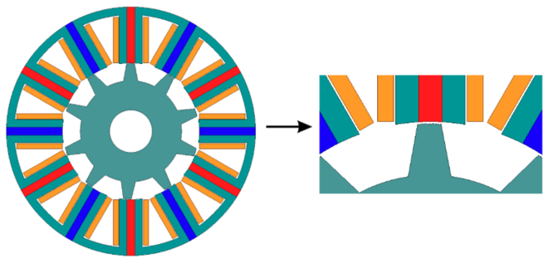
The initial model referenced in this study is a three-phase, 12-slot, 10-pole FSPM machine. The electrical and geometric characteristics of this selected basic design are detailed in
Table 1 and a two-dimensional cross-section of the machine is shown in
Figure 1.
When studies in the literature are examined, it can be seen that FSPM machines are a strong alternative to conventional Internal Magnet (IPM) machines in terms of both mechanical robustness and electromagnetic performance [
15]. In particular, in the FSPM structure examined, the positioning of both the armature windings and the permanent magnets on the stator ensures that the rotor has a passive structure consisting only of laminated steel [
10]. This situation, as highlighted in [
16], eliminates the risk of damage to the magnets due to centrifugal force and offers significant mechanical reliability in high-speed applications.
The spoke-type magnets placed tangentially between the stator teeth create a significant “flux focusing” effect in the air gap, allowing for much higher torque density compared to the surface-mounted machines mentioned in [
17,
18]. The 12-slot/10-pole combination was selected over alternative topologies such as 12/14 and 24/20 based on several complementary advantages. Although the 24/20 configuration shares a similar winding factor, the 12s/10p topology offers a more compact and lightweight structure due to its lower slot and pole count, which reduces iron losses and manufacturing complexity. Furthermore, compared to the 12/14 combination, the 12s/10p topology provides a more favorable balance between cogging torque frequency and amplitude, as the higher least common multiple (LCM) between stator slots and rotor poles results in lower cogging torque magnitude per cycle. In addition, this topology benefits from a short flux path between adjacent stator poles, which enhances flux linkage efficiency and reduces copper losses compared to distributed winding alternatives. The symmetrical structure of the 12s/10p configuration also ensures balanced radial force distribution, contributing to reduced vibration and acoustic noise during operation [
19]. The main objective of this study is to expand the electromagnetic performance limits of the reference model; to optimize the fluctuating moment, average torque, back-EMF harmonics and torque ripple parameters. Analysis and optimization studies were carried out using the 2D finite element method (FEM) with Ansys Maxwell 2024. To accurately model regions approaching saturation, nonlinear B-H curves were used for both the M300-35A electrical steel core and the NdFe35 permanent magnets, and accuracy was maximized by applying a fine mesh density setting in the air-gap region. A balloon boundary condition was assigned at the outer boundary of the solution domain to approximate an open-field condition. The armature windings were excited using a sinusoidal current source at the rated peak current of 3.8 A and rated speed of 1200 rpm. A transient solver was employed for the main analysis with a simulation duration of 10 ms at 1200 rpm, which is sufficient to capture the steady-state electromagnetic behavior. Cogging torque was extracted from a separate transient simulation performed with zero armature current at 3 rpm, with a simulation duration of 250 ms and a time step of
s, over one full electrical period at
angular increments starting from an initial rotor position of
, and back-EMF was obtained from a no-load transient simulation. For material selection, M300-35A class electrical steel was chosen for the stator and rotor, and high coercivity NdFe35 was preferred for permanent magnets.
3. Proposed Techniques
This section details the optimization methods applied to improve the electromagnetic performance of the FSPM machine, which is considered as the basic design. The main objective of these studies is to increase the torque density of the motor, minimize torque ripple and cogging torque to achieve a more stable and smoother operating characteristic, and reduce negative magnetic effects in the air gap. One of the fundamental elements determining the electromagnetic performance in FSPM machines is the magnetic permeance distribution resulting from the stator–rotor interaction. Therefore, it is known in the literature that permeance-based optimizations performed on the machine geometry play a critical role in performance improvement. This study adopts a three-stage optimization approach, with each method building upon the previous one to create a foundation for further development. In the first stage, a comprehensive optimization process based on GA and 2D FEA focusing on the rotor pole geometry for an FSPM machine with 12 stator slots and 10 rotor poles (12s/10p) was conducted. In this stage, the basic structure with a conventional and symmetrical rotor geometry was first defined as D0 (reference model) and used as a benchmark for all subsequent designs.
3.1. Notching Method
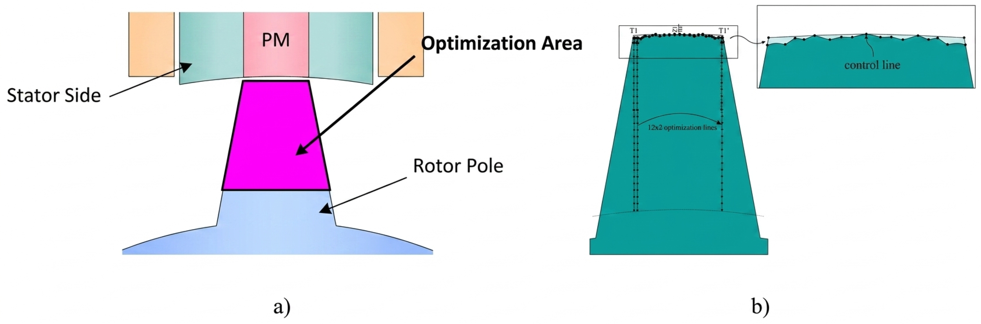
In the first optimization stage, the rotor pole surface of the reference design (D0) was parameterized using 24 control points distributed along the pole profile, as illustrated in
Figure 2b. These points were allowed to move freely within geometrically defined boundaries, enabling a flexible freeform shaping of the rotor pole without imposing a predefined notch geometry. This approach provides a high degree of geometric freedom while ensuring that the resulting shapes remain physically realizable and manufacturable. The optimization was carried out by coupling 2D-FEA with a genetic algorithm. The GA explored the defined parameter space by evaluating candidate rotor pole geometries across successive generations, with each candidate assessed through a full 2D-FEA simulation in Ansys Maxwell. The resulting torque characteristics were fed back to the algorithm to guide the search in subsequent iterations. The primary objective of the optimization was to maximize average torque beyond the reference value, while the secondary objective was to minimize peak-to-peak torque ripple. This priority ordering ensured that improvements in torque smoothness were never achieved at the expense of torque output. Two designs—D1 and D2—emerged from this process, differing in the degree of geometric freedom applied to the control-point boundaries, and both demonstrated significant improvements in torque profile compared to D0.
Within this optimization framework, two different advanced design models based on notching for rotor pole shaping were developed, taking the reference design as a basis. These models, named D1 and D2, although differing in terms of geometric degrees of freedom, both apply a notching approach based on controlled material removal on the rotor pole surface. In the D1 model, the aim was to make the magnetic flux transitions more balanced and reduce local saturation effects through a limited number of control points defined on the rotor pole surface. In the D2 model, the notching geometry was defined more freely by using a larger number of control points, thus directing the magnetic field distribution around the rotor pole more effectively. The optimization results for both models showed that the magnetic flux transitions in the air gap were smoothed, the average torque was increased, and the torque fluctuation was significantly reduced compared to the reference design. These findings reveal that notching geometry rotor pole shaping is an effective method for improving torque performance in FSPM-like machines [
11].
3.2. Unequal Rotor Slot Arc (URSA) Method
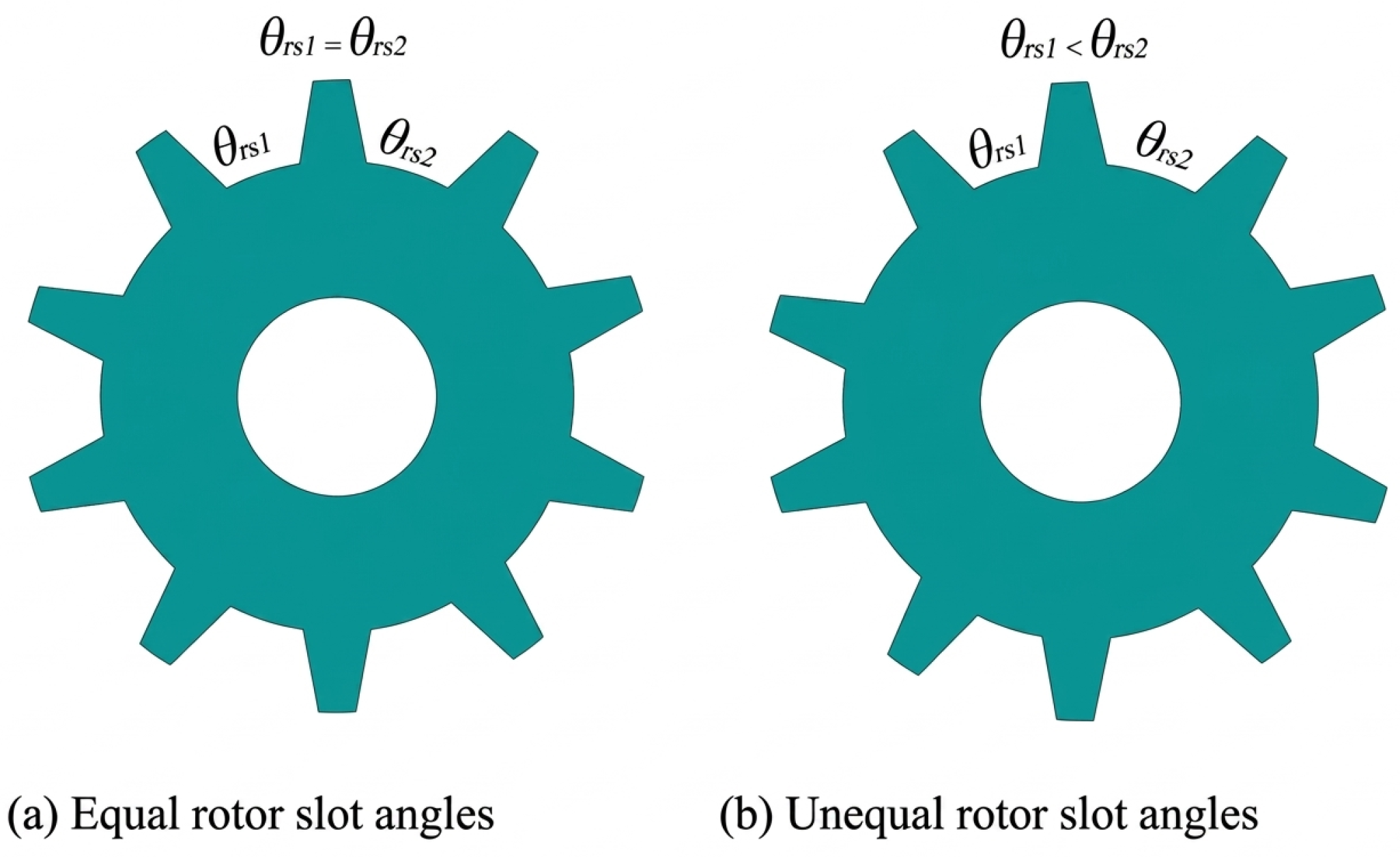
The second fundamental optimization approach focuses on reducing cogging torque, a key component of torque ripple in FSPM machines. For this purpose, the rotor geometry was considered efficient in directly and effectively directing the magnetic permeance distribution due to the presence of only magnetic steel on the rotor side. Taking advantage of this structural advantage compared to other permanent magnet machines, a rotor-based solution instead of a stator-based one was adopted for cogging torque reduction, and optimization studies were carried out using the rotor slot geometry. In this context, a method called URSA in the literature has been applied. Instead of the symmetrical and equal-angle rotor slot structure used in classical designs, successive rotor slot openings are deliberately arranged in unequal angular distributions. This asymmetrical structure balances magnetic energy oscillations by changing the spatial distribution of magnetic permeance in the air gap, thus contributing to the suppression of the cogging moment. With the URSA approach, magnetic permeance harmonics on the rotor are weakened, and the effect of interactions causing torque fluctuations is reduced.
In the URSA-based optimization process, the rotor slot geometry was defined by the angular parameters
and
, and these parameters were systematically modified based on the reference equiangular rotor design (D0). Parametric FEA was performed to determine the effect of the change in magnetic permeance distribution on electromagnetic performance. As a result of the analyses, two different rotor configurations stood out. In the D3 design, which provides the lowest cogging moment and balanced magnetic flux distribution, it was determined that the first rotor slot arc was increased by
compared to the reference value, while the second slot arc was narrowed by
. In the D4 design, obtained as an alternative solution, similarly successful results were obtained with the angular combination of
and
. These specific parameter combinations were determined with the primary objective of introducing effective asymmetry while avoiding excessive geometric irregularity between the rotor slot arcs.The geometric arrangements given in
Figure 3b demonstrate that the magnetic permeance distribution on the rotor side can be effectively controlled and that the URSA method is a powerful optimization tool for reducing the cogging torque in FSPM machines [
12].
3.3. The URSA-Notch Hybrid Method
In the third and final stage, an integrated optimization process was developed by combining the freeform-based rotor pole optimization discussed in previous sections with the URSA approach based on unequal rotor slot openings. The geometric parameters of both methods were defined within the same design space and optimization was applied simultaneously. In the developed hybrid optimization method, the micro-scale freeform reshaping of the rotor pole profile—parameterized using 24 control points—and the macro-scale asymmetric arrangement of the rotor slots through the angular parameters
and
were applied together on the same rotor geometry. Thus, the magnetic flux distribution around the rotor pole and the magnetic permeance profile in the air gap were controlled simultaneously, overcoming the limitations of traditional methods that focus only on the pole shape or only on the slot openings. The primary objective was to preserve and preferably increase the average torque value, while minimizing cogging torque and peak-to-peak torque ripple. In the hybrid design process, the D0 model was taken as the reference design; the hybrid design obtained by applying the URSA approach together with notch-based geometric arrangements is shown in
Figure 4.
The optimization generated over 300 candidate solutions, each evaluated through 2D-FEA in Ansys Maxwell. To avoid computational complexity while preserving design diversity, the six best-performing solutions were selected from the full solution set for detailed comparative analysis, and three hybrid designs, D5, D6, and D7, were determined as the final models. These designs exclusively incorporate the hybrid optimization method, combining both rotor pole freeform notching and asymmetric slot arc, and do not include any single-method configurations. The findings revealed that the hybrid optimization approach surpasses the gains achieved with rotor pole shaping alone or URSA-based optimization methods alone. In particular, designs D5, D6, and D7 were found to offer superior electromagnetic performance compared to both the reference model and the designs from the intermediate optimization stages, especially in terms of the balance between average torque and torque ripple. Consequently, the hybrid optimization strategy proposed in this study is considered to offer an effective, feasible, and high-performance design approach for reducing cogging torque and torque ripple in FSPM machines.
Table 2 details which optimization approaches are represented by the design numbers discussed in this study.
4. Electromagnetic Analysis Results
In this section, the electromagnetic performance of the reference design (D0) and the models to which the proposed optimization methods (D1–D7) are applied is examined in a comprehensive and comparative approach. The analysis process is structured around four main axes: average torque and torque ripple, back-EMF value, cogging torque, and torque generation capacity at different current densities. The main objective of this study is to demonstrate, with concrete data, the effectiveness of the hybrid and singular optimization strategies detailed in
Table 2 in minimizing vibration and acoustic noise sources, which are characteristic disadvantages of FSPM motors.
4.1. Average Torque and Torque Ripple
Although the rotor and stator pole magnetic interactions in FSPM machines are inherently capable of generating high torque, this often leads to undesirable torque ripple.
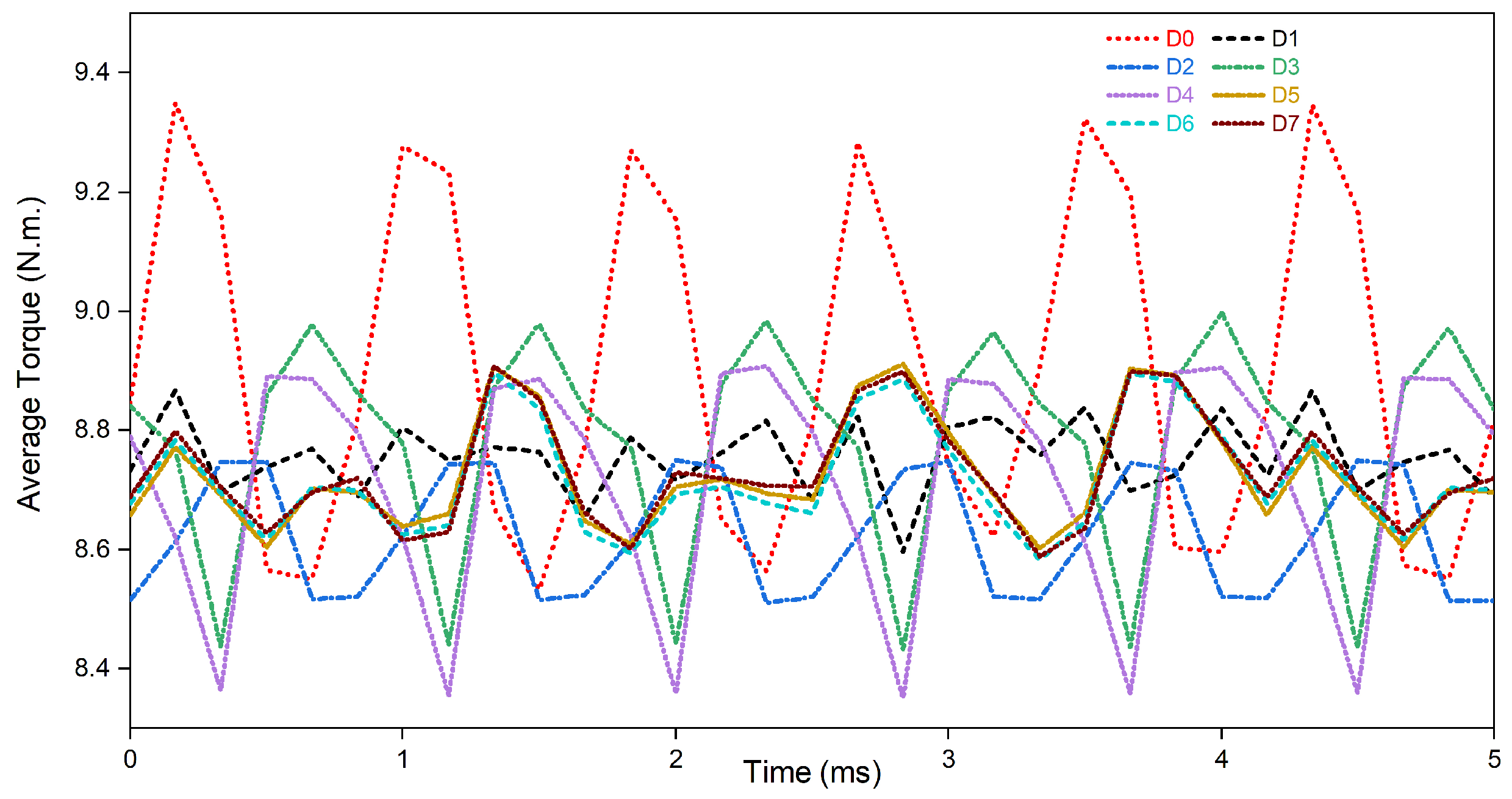
Figure 5 presents the torque profiles of the reference model (D0) and seven different optimized models (D1–D7) under nominal operating conditions.
When the graph is examined, it is seen that the reference model (D0) has a high-amplitude torque ripple, whereas this ripple is significantly suppressed in all designs where the proposed methods are applied. In particular, it is noteworthy that the torque value is transformed into a smoother form in the designs where the rotor pole notch forming (D1, D2) and URSA (D3, D4) methods are applied individually. However, the most significant improvement is observed in the hybrid designs (D5, D6, D7) that combine the advantages of both methods. These models not only minimize the ripple but also provide a stable output without compromising the average torque value (and even improving the instantaneous torque in some angles). This proves that hybrid optimization dampens sudden moment pulses caused by reluctance changes by regulating magnetic flux paths, and allows the motor to exhibit quieter and vibration-free, i.e., smoother operation.
4.2. Back Electromotive Force (Back-EMF)
One of the most critical electromagnetic parameters directly affecting the motor’s performance in generator mode and its compatibility with power electronics-based motor drives is the back-EMF waveform. The amplitude, waveform, and harmonic content of the back-EMF play a dominant role in terms of energy conversion efficiency, torque ripple, and the performance of drive control approaches. In this context,
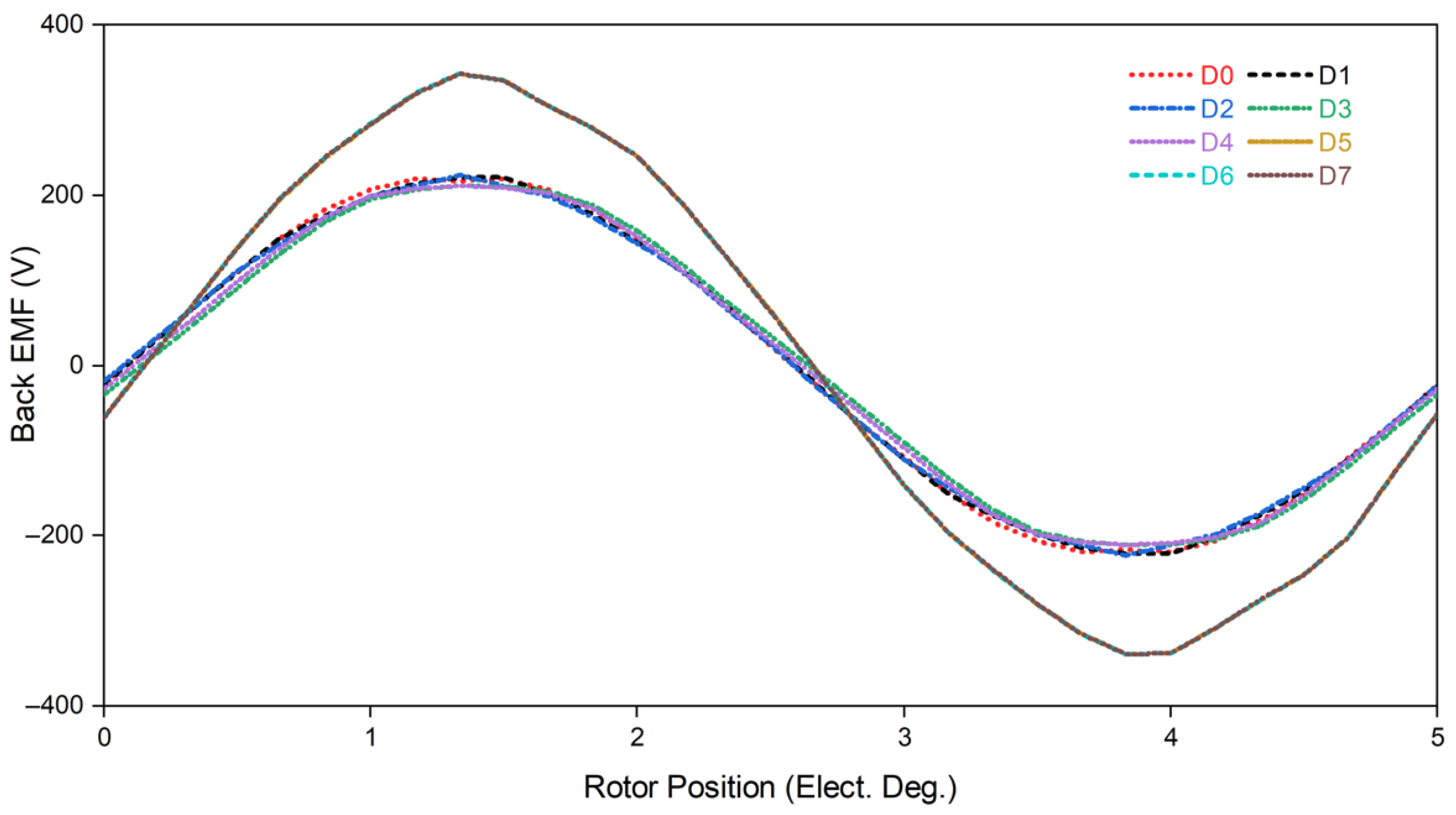
Figure 6 comparatively shows the time-dependent variations in the back-EMF waveforms induced per phase for the reference design and the proposed optimized models.
The results indicate that structural optimizations (notching and asymmetric model structure) do not distort the fundamental sinusoidal waveform; on the contrary, they improve the harmonic content of the waveform, providing a model closer to the ideal sine wave. The most important finding in the graph is that the models developed with the hybrid optimization method (especially D5 and D7) have a higher back-EMF amplitude compared to other models. This increase in amplitude indicates that the optimized rotor structure utilizes the flux linkage in the air gap more efficiently and increases the amount of effective flux interacting with the windings. A higher back-EMF amplitude means a higher power generation potential at the same speed, confirming that the proposed hybrid method makes a positive contribution to electrical efficiency.
4.3. Cogging Torque
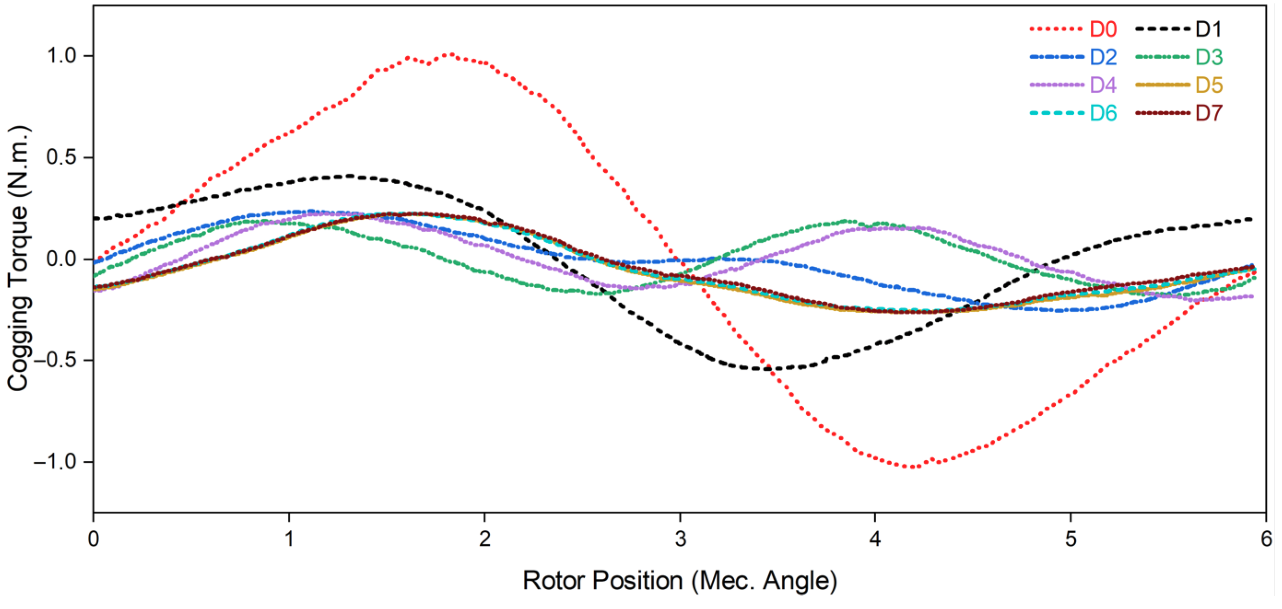
In permanent magnet machines, the main source of vibration and acoustic noise, which negatively affects operation, especially at low speeds, is the cogging torque.
Figure 7 shows the variations in cogging torque exhibited by the models optimized with the D0 reference design over one electrical period. The reference design (D0), represented in red in the graph, clearly exhibits high peak-to-peak torque values due to the high magnetic attraction forces between the stator teeth and the magnets. In contrast, all of the developed optimization methods (D1–D7) have been highly effective in reducing this value. The asymmetric distribution of notches and URSA smoothed the magnetic permeance variations in the air gap, preventing sudden changes in magnetic energy. The results show that the optimized designs reduce the torque to negligible levels. This improvement not only increases the stability of the motor during startup but also guarantees its suitability for applications requiring precise positioning.
4.4. Load Condition and Torque Density
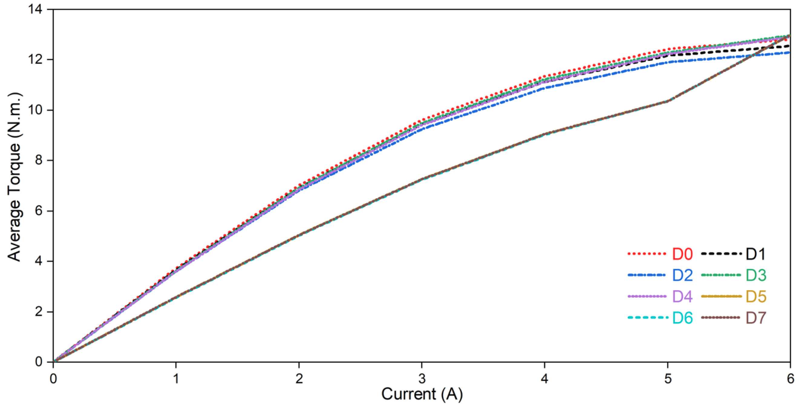
To measure the motor’s response under different operating conditions, the average torque variation (torque density/load capacity) obtained by increasing the armature current is examined in
Figure 8. This analysis is critical for observing the effect of optimized geometries on saturation.
According to the simulation results, as the current level increases, the torque production capacity of all designs (D1–D7) converges, showing a trend similar to the reference design (D0). At low and medium current levels, the optimized designs retain the advantages of reduced knocking and ripple; while at high current levels, as the magnetic core of the motor approaches saturation, the torque curves continue to maintain their linear characteristics. This shows that the notching and geometric shifting operations performed on the rotor do not negatively affect the maximum load-carrying capacity or torque density of the motor. In other words, the proposed “green and efficient” design approach has succeeded in improving the operating quality of the motor without compromising its power density.
5. Magnetic Flux Density and Magnetic Field Intensity
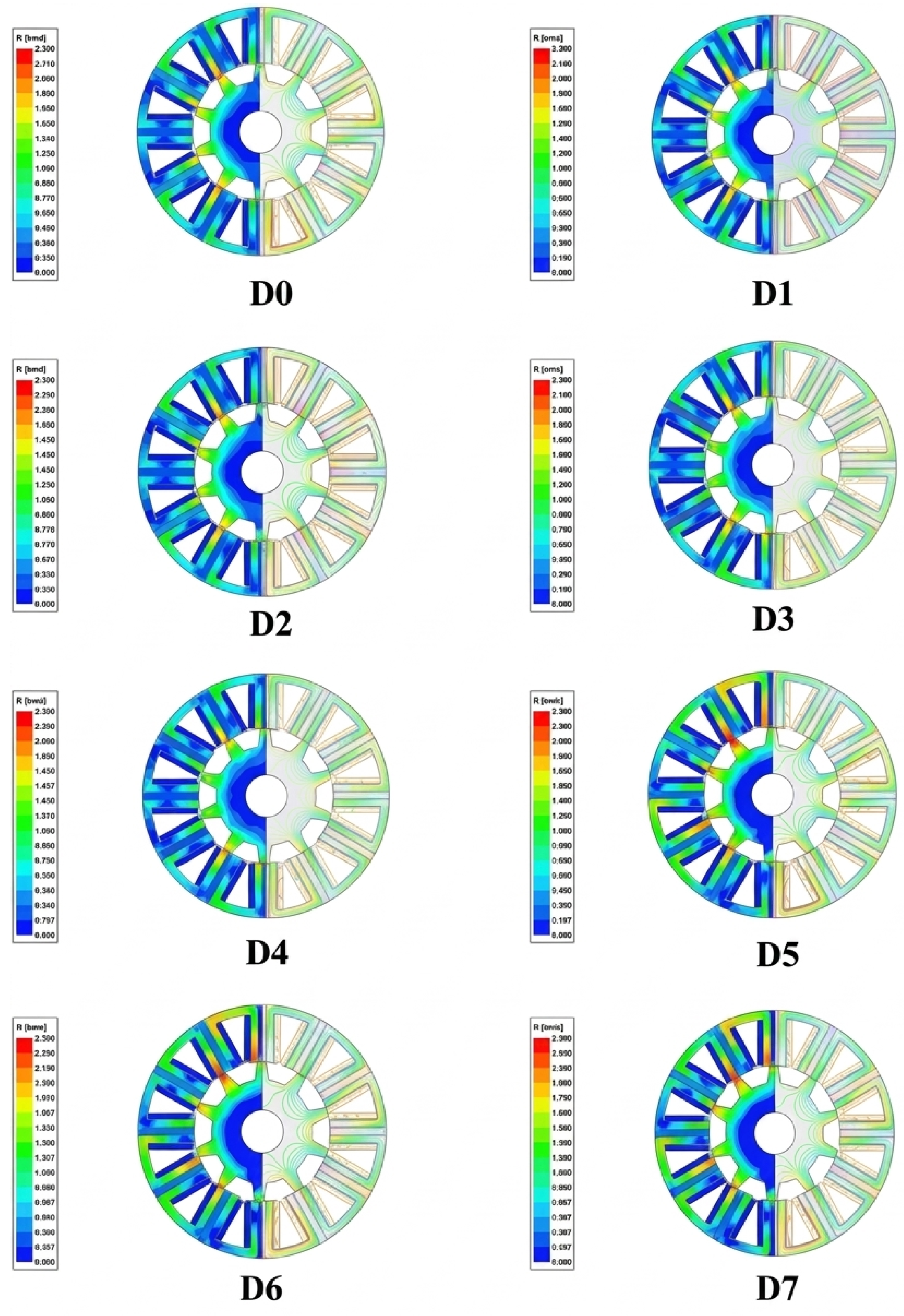
Figure 9 shows the two-dimensional magnetic flux density distributions and magnetic field lines under load for all designs D0–D7. These visualizations provide an important analytical opportunity to evaluate whether the models obtained by applying rotor notching and asymmetric slot geometries together cause regional saturation in the motor’s magnetic circuit.
A detailed examination reveals that the developed hybrid designs exhibit a high level of stability and continuity in terms of magnetic flux distribution. Particularly in key regions where magnetic flux is concentrated, such as stator tooth tips and rotor pole corners, the flux density values remain below the saturation limits defined for the M300-35A magnetic material. It is worth noting that designs D5–D7, which incorporate asymmetric rotor slot arcs, exhibit a slightly higher flux density under one rotor tooth compared to the reference design D0. This localized increase is a direct consequence of the deliberate asymmetry introduced by the URSA method: the narrower slot arc on one side reduces the effective flux path cross-section, resulting in a marginally elevated flux density in the adjacent rotor tooth. Importantly, however, the flux density in these regions remains within the linear operating range of the M300-35A material and does not reach saturation levels that would degrade performance. This behavior confirms that the observed non-uniformity is an intended and controlled outcome of the asymmetric optimization, rather than an undesirable saturation artifact.
When the distribution of magnetic field lines was evaluated, it was observed that the notches and asymmetric groove geometry created on the rotor did not interrupt the main flux path or cause any significant irregularity, breakage, or leakage flux increase. In contrast, the flux lines were distributed regularly and homogeneously along the magnetic circuit, indicating that electromagnetic interactions were maintained in a healthy manner.
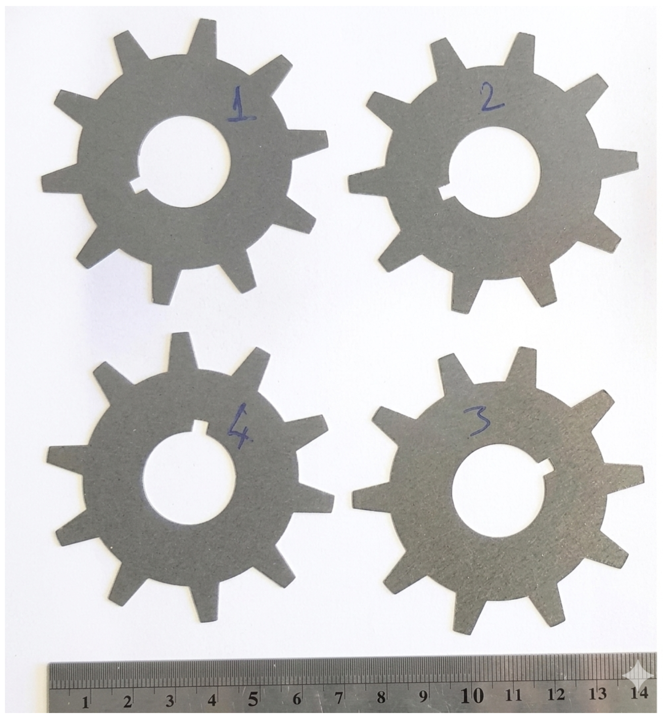
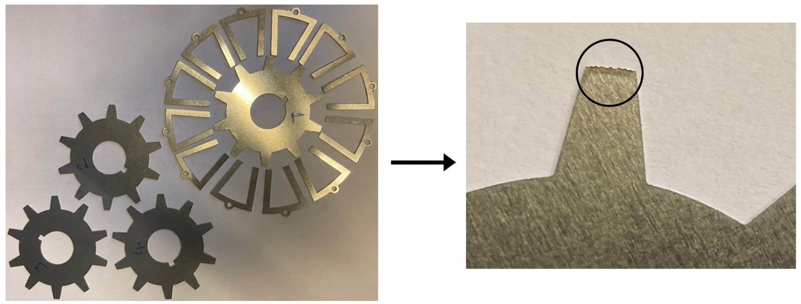
Having thoroughly validated the electromagnetic performance through comprehensive FEA, the next critical step is to assess their physical realizability. The highly complex, micro-scaled freeform notches and asymmetric rotor geometries introduce potential manufacturing challenges compared to conventional topologies. Therefore, rotor and stator laminations were produced as trial productions to evaluate the structural manufacturability of these optimized geometries.
Figure 10 and
Figure 11 show that four different geometries were created from M300-35A steel sheet using laser cutting: the basic design, the design improved by the notching method, the design obtained by the URSA method, and the final design obtained using hybrid methods. These figures demonstrate that the produced FSPM machine sections can be manufactured with complete accuracy according to the design. Particular care must be taken during the production process due to the very high precision of the rotor pole ends. Ultimately, it has been proven that the improved designs can be physically produced within acceptable laser-cutting tolerances, providing a viable and reliable modeling method for practical applications.
In conclusion, it has been confirmed that the proposed optimized geometries do not create any magnetic constraints; they successfully achieve the targeted performance improvements, such as minimizing torque ripple, while maintaining electromagnetic reliability and structural integrity.
Table 3 shows that improvements in torque ripple and cogging torque characteristics are achieved for each proposed design without any noticeable average torque loss. While this study validates the theoretical performance via FEA and proves structural manufacturability, the full experimental performance validation of the assembled motor prototype—including dynamic torque and efficiency measurements under actual load conditions—is planned as the primary focus of future work.
6. Conclusions
Comparative evaluation of the performance outputs of FSPM machine designs (D0–D7) clearly shows an interaction between average torque, torque ripple, and cogging torque. It has been observed that improvements in one of these parameters have limited effects on other performance parameters. Although the original design D0, considered as a reference, produces the highest average torque value at 8.9 Nm, it exhibits a problematic profile in terms of electromechanical vibration and acoustic performance due to a torque ripple of 9.2% and a cogging torque of 2.03 Nm. This result reveals that torque magnitude alone is not sufficient to define design adequacy. Among the optimized models, the most significant improvement in terms of torque ripple was obtained from design D1. In the D1 configuration, the ripple ratio was reduced from 9.2% to 1.59%, representing an approximately 83% reduction—equivalent to roughly a sixfold decrease in torque fluctuation compared to D0. Notably, this improvement was achieved with only a 1.5% reduction in average torque, which is considered the key factor that makes D1 stand out in terms of performance–stability balance. In terms of cogging torque, design D3 achieved the lowest value among all designs at 0.4 Nm. Furthermore, maintaining cogging torque below 0.5 Nm across all optimized models from D2 to D7 demonstrates that the proposed geometric arrangements have produced a stable and repeatable reducing effect on this parameter. This indicates that the cogging torque reduction is not specific to a single design configuration, but rather reflects the overall success of the applied optimization approach. In the overall assessment, the D1 design stands out as the most suitable solution for applications where minimizing torque fluctuation is a priority, while the D3 design is best suited for systems where low cogging torque is critical. These findings clearly demonstrate the necessity of a balance-oriented design approach based on application requirements, rather than a universal single-solution selection strategy. In conclusion, the proposed rotor notching, URSA, and hybrid optimization methods represent a promising engineering framework applicable in the manufacturing processes of high-performance FSPM machines for green industry applications. The analyses and optimization processes presented in this study cover the theoretical and 2D-FEA-based electromagnetic performance evaluations of the proposed FSPM machine designs. To fully verify the practical applicability of the promising improvements obtained from the simulations, the physical prototype manufacturing of the optimized final motor design is currently underway. In future studies, which are planned as the next phase of this research, comprehensive experimental tests including dynamic torque, back-EMF, and detailed efficiency map measurements will be conducted on the assembled prototype. Additionally, performing structural stress analyses to verify the physical integrity of the asymmetric rotor at high speeds, as well as 3D-FEA to investigate end-effects and correlating them with experimental results, are targeted as the main focus of our upcoming work.
Author Contributions
Conceptualization, B.T. and E.C.; methodology, B.T.; software, B.T.; validation, B.T., E.C. and Z.T.; formal analysis, B.T.; investigation, B.T. and E.C.; resources, B.T.; data curation, B.T.; writing—original draft preparation, B.T.; writing—review and editing, B.T. and E.C.; visualization, B.T.; supervision, E.C.; project administration, B.T.; funding acquisition, E.C. All authors have read and agreed to the published version of the manuscript.
Funding
This research was funded by Scientific and Technological Research Council of Turkey grant number [124E478].
Institutional Review Board Statement
Not applicable.
Informed Consent Statement
Not applicable.
Data Availability Statement
The data presented in this study are available within the article.
Acknowledgments
The authors would like to thank the Scientific and Technological Research Council of Türkiye (TÜBİTAK) for their financial support under project number [124E478]. We also acknowledge the technical support provided by Ansys Maxwell for electromagnetic simulations. During the preparation of this manuscript, the authors used Gemini 3.1 Pro for the purpose of language editing. The authors have reviewed and edited the output and take full responsibility for the content of this publication.
Conflicts of Interest
The authors declare no conflicts of interest.
Abbreviations
The following abbreviations are used in this manuscript:
| 2D | Two-Dimensional |
| Back-EMF | Back-Electromotive Force |
| FEA | Finite Element Analysis |
| FEM | Finite Element Method |
| FSPM | Flux-Switching Permanent Magnet |
| PM | Permanent Magnet |
| SRM | Switched Reluctance Motor |
| GA | Genetic Algorithm |
| IPM | Internal Permanent Magnet |
| NdFe35 | Neodymium Magnet |
| URSA | Unequal Rotor Slot Arc |
References
- Tepretmez, B.; Cetin, E. A review on strategies for minimizing cogging torque in flux-switching permanent magnet machines. Omer Halisdemir Univ. J. Eng. Sci. 2025, 14, 1155–1170. [Google Scholar] [CrossRef] [Scilit]
- Svetlik, P.; Hruska, K. Construction of the FSPM machine and its measurement in comparison with modeled results. In Proceedings of the 18th European Conference on Power Electronics and Applications (EPE’16 ECCE Europe), Karlsruhe, Germany, 13–15 September 2016; pp. 1–9. [Google Scholar] [CrossRef] [Scilit]
- Li, F.; Hua, W.; Tong, M.; Zhao, G.; Cheng, M. Nine-phase flux-switching permanent magnet brushless machine for low-speed and high-torque applications. IEEE Trans. Magn. 2015, 51, 8700204. [Google Scholar] [CrossRef] [Scilit]
- Mirnikjoo, S.A.; Abbaszadeh, K.; Abdollahi, S.E. Design of an outer rotor flux switching permanent magnet generator for wind turbine. In Proceedings of the 11th Power Electronics, Drive Systems, and Technologies Conference (PEDSTC), Tehran, Iran, 4–6 February 2020; pp. 1–6. [Google Scholar] [CrossRef] [Scilit]
- Zhang, W.; Lin, M.; Xu, D.; Fu, X.; Hao, L. Novel fault-tolerant design of axial field flux-switching permanent magnet machine. IEEE Trans. Appl. Supercond. 2014, 24, 0503804. [Google Scholar] [CrossRef] [Scilit]
- Cao, L.; Chau, K.T.; Lee, C.H.T.; Wang, H. A double-rotor flux-switching permanent-magnet motor for electric vehicles with magnetic differential. IEEE Trans. Ind. Electron. 2021, 68, 1004–1015. [Google Scholar] [CrossRef] [Scilit]
- Boldea, I.; Tutelea, L.N.; Parsa, L.; Dorrell, D. Automotive electric propulsion systems with reduced or no permanent magnets: An overview. IEEE Trans. Ind. Electron. 2014, 61, 5696–5711. [Google Scholar] [CrossRef] [Scilit]
- Hwang, S.-M.; Eom, J.-B.; Hwang, G.-B.; Jeong, W.-B.; Jung, Y.-H. Cogging torque and acoustic noise reduction in permanent magnet motors by teeth pairing. IEEE Trans. Magn. 2000, 36, 3144–3146. [Google Scholar] [CrossRef] [Scilit]
- Ahn, J.-W.; Lukman, G.F. Switched reluctance motor: Research trends and overview. CES Trans. Electr. Mach. Syst. 2018, 2, 339–347. [Google Scholar] [CrossRef] [Scilit]
- Chen, H.; EL-Refaie, A.M.; Demerdash, N.A.O. Flux-switching permanent magnet machines: A review of opportunities and challenges—Part II: Design aspects, control, and emerging trends. IEEE Trans. Energy Convers. 2020, 35, 699–713. [Google Scholar] [CrossRef] [Scilit]
- Cetin, E.; Zhu, Z.Q. Rotor pole and stator tooth shaping in FSPM machines for torque performance optimization. COMPEL Int. J. Comput. Math. Electr. Electron. Eng. 2025, 44, 149–165. [Google Scholar] [CrossRef] [Scilit]
- Cetin, E. Cogging torque reduction by utilizing the unequal rotor slot arc method for FSPM machines. Ain Shams Eng. J. 2024, 15, 103008. [Google Scholar] [CrossRef] [Scilit]
- Zhu, Z.Q.; Chen, J.T. Advanced flux-switching permanent magnet brushless machines. IEEE Trans. Magn. 2010, 46, 1447–1453. [Google Scholar] [CrossRef] [Scilit]
- Hua, W.; Cheng, M.; Zhu, Z.Q.; Howe, D. Analysis and optimization of back EMF waveform of a flux-switching permanent magnet motor. IEEE Trans. Energy Convers. 2008, 23, 727–733. [Google Scholar] [CrossRef] [Scilit]
- Pang, Y.; Zhu, Z.Q.; Howe, D.; Iwasaki, S.; Deodhar, R.; Pride, A. Comparative study of flux-switching and interior permanent magnet machines. In Proceedings of the International Conference on Electrical Machines and Systems (ICEMS), Seoul, Republic of Korea, 8–11 October 2007; pp. 757–762. [Google Scholar] [CrossRef] [Scilit]
- Bobba, D.; Li, Y.; Sarlioglu, B. Harmonic analysis of low stator slot and rotor pole combination FSPM machine topology for high speed. In Proceedings of the IEEE Magnetics Conference (INTERMAG), Beijing, China, 11–15 May 2015; p. 1. [Google Scholar] [CrossRef] [Scilit]
- Wang, Q.; Zhao, X.; Niu, S. Flux-modulated permanent magnet machines: Challenges and opportunities. World Electr. Veh. J. 2021, 12, 13. [Google Scholar] [CrossRef] [Scilit]
- Pellegrino, G.; Vagati, A.; Guglielmi, P.; Boazzo, B. Performance comparison between surface-mounted and interior PM motor drives for electric vehicle application. IEEE Trans. Ind. Electron. 2012, 59, 803–811. [Google Scholar] [CrossRef] [Scilit]
- Li, L.; Liu, Y.; Zhao, G.; Ding, Y.; Hua, W. Research on combinations of stator poles and rotor teeth for conventional flux-switching brushless machines with composite phase numbers. Electronics 2025, 14, 3405. [Google Scholar] [CrossRef] [Scilit]
Figure 1.
2D visualization of the basic design of the FSPM machine.
Figure 1.
2D visualization of the basic design of the FSPM machine.
Figure 2.
(a) Identification of the optimization area on the rotor pole. (b) Schematic representation of optimization lines and surface profile details.
Figure 2.
(a) Identification of the optimization area on the rotor pole. (b) Schematic representation of optimization lines and surface profile details.
Figure 3.
URSA method: (a) reference equiangular rotor slot configuration (D0), illustrating the equal angular distribution of successive rotor slot openings; (b) asymmetric rotor slot arrangement showing the modified angular parameters and as applied in the D3 and D4 designs, where is increased and is reduced relative to the reference value to introduce controlled magnetic permeance asymmetry.
Figure 3.
URSA method: (a) reference equiangular rotor slot configuration (D0), illustrating the equal angular distribution of successive rotor slot openings; (b) asymmetric rotor slot arrangement showing the modified angular parameters and as applied in the D3 and D4 designs, where is increased and is reduced relative to the reference value to introduce controlled magnetic permeance asymmetry.
Figure 4.
Hybrid model design.
Figure 4.
Hybrid model design.
Figure 5.
Average torque values of D0–D7 models.
Figure 5.
Average torque values of D0–D7 models.
Figure 6.
Back-EMF values of D0–D7 models.
Figure 6.
Back-EMF values of D0–D7 models.
Figure 7.
Cogging torque values of D0–D7 models.
Figure 7.
Cogging torque values of D0–D7 models.
Figure 8.
Torque density values of D0–D7 models.
Figure 8.
Torque density values of D0–D7 models.
Figure 9.
2D magnetic flux density distributions and magnetic field lines under load for designs D0–D7.
Figure 9.
2D magnetic flux density distributions and magnetic field lines under load for designs D0–D7.
Figure 10.
Laser-cut rotor cross-sections of four design variants: the reference model (D0), the notching-optimized design (D1), the URSA-optimized design (D3), and the hybrid-optimized design (D5). Each cross-section corresponds directly to the FEA model bearing the same design identifier.
Figure 10.
Laser-cut rotor cross-sections of four design variants: the reference model (D0), the notching-optimized design (D1), the URSA-optimized design (D3), and the hybrid-optimized design (D5). Each cross-section corresponds directly to the FEA model bearing the same design identifier.
Figure 11.
Laser-cut stator and rotor laminations of the trial prototype (left), and a close-up view of the notch-optimized rotor pole tip (right), where the circled region highlights the freeform-shaped surface profile achieved through the rotor pole shaping method.
Figure 11.
Laser-cut stator and rotor laminations of the trial prototype (left), and a close-up view of the notch-optimized rotor pole tip (right), where the circled region highlights the freeform-shaped surface profile achieved through the rotor pole shaping method.
Table 1.
Design parameters and material characteristics of the electric motor.
Table 1.
Design parameters and material characteristics of the electric motor.
| Parameter | Unit | Value |
|---|
| Number of Phases | - | 3 |
| Stator Slots/Rotor Poles | - | 12s/10p |
| Peak Current | A | 3.8 |
| Rated Speed | rpm | 1200 |
| Rated Power | W | 1100 |
| Stator Outer Diameter | mm | 128 |
| Stator Inner Diameter | mm | 70.4 |
| Rotor Outer Diameter | mm | 69.8 |
| Rotor Inner Diameter | mm | 22 |
| Machine Length | mm | 75 |
| Number of Turns per Phase | - | 280 |
| Permanent Magnet Remanence | T | 1.2 |
| Permanent Magnet Relative Permeability | - | 1.05 |
| Permanent Magnet Coercivity | kA/m | −909.46 |
Table 2.
Designations and applied optimization methods of the proposed models.
Table 2.
Designations and applied optimization methods of the proposed models.
| Design Method | Design Number |
|---|
| Original design | D0 |
| Rotor notching method | D1 |
| Rotor notching method | D2 |
| URSA method | D3 |
| URSA method | D4 |
| Hybrid optimization method | D5 |
| Hybrid optimization method | D6 |
| Hybrid optimization method | D7 |
Table 3.
Electromagnetic performance indices of different design configurations.
Table 3.
Electromagnetic performance indices of different design configurations.
| DESIGN |
|---|
| | D0 | D1 | D2 | D3 | D4 | D5 | D6 | D7 |
|---|
| Average Torque (Nm) | 8.9 | 8.76 | 8.65 | 8.78 | 8.7 | 8.73 | 8.72 | 8.73 |
| Torque Ripple (%) | 9.2 | 1.59 | 2.8 | 6.4 | 6.46 | 3.53 | 3.61 | 3.67 |
| Cogging Torque (Nm) | 2.03 | 0.92 | 0.48 | 0.4 | 0.43 | 0.48 | 0.47 | 0.48 |
| Disclaimer/Publisher’s Note: The statements, opinions and data contained in all publications are solely those of the individual author(s) and contributor(s) and not of MDPI and/or the editor(s). MDPI and/or the editor(s) disclaim responsibility for any injury to people or property resulting from any ideas, methods, instructions or products referred to in the content. |