2. Literature Review
Over the past decade, vehicle hardware architecture has changed dramatically. The number of electronic control units (ECUs) now often exceeds 100, and software size has grown beyond 100 million lines of code—a scale that rivals or exceeds many other complex systems, including modern aircraft and large online platforms Liu and Shi [
2].
The next step is a shift to software-defined vehicles (SDVs) with zonal architectures: fewer physical controllers, greater per-node computational power, and centralised software functions. This transition enables efficiency gains by removing redundant functionality and supports continuous improvement through over-the-air (OTA) updates Malik et al. [
3]. Such fundamental changes in hardware and software demand careful attention to compatibility, scalability, and robustness during design and development. Zonal architecture includes a telemetric control unit and a gateway domain controller. An Ethernet backbone provides high-bandwidth, reliable communication among centralised, domain-specialised controllers: powertrain, chassis, body, safety, and infotainment Komorkiewicz et al. [
4].
Given these innovations, both systems engineering and software development pipelines must be revised to support the new architecture.
ISO 26262 is an international standard that provides comprehensive guidelines for the safe design and development of electrical/electronic (E/E) systems in vehicles. It defines functional safety, assesses risks via automotive safety integrity levels (ASILs), and covers the entire lifecycle from concept to decommissioning to minimise hazards from system malfunctions. Based on this standard, system development lifecycles are based on the V-model [
5]. The V-model delineates a sequential progression, from defining system requirements through design concepts, detailed component-level design, and manufacturing to a series of verification and validation activities, including component-level testing, system-level testing, and full model testing before operation. Each function has input requirements (at the level of study) and output requirements (one level higher) Wagg et al. [
6]. The W-model extends this model by integrating additional early-stage testing activities, such as test planning and scenario identification, alongside the traditional verification and validation phases. The V-model remains dominant, and ISO 26262 is aligned for traceability and safety in automotive E/E systems, including chassis domain controllers and actuators, but its limitations (rigidity, late integration, limited support for continuous improvement, and slow development speed) persist. The W-model offers marginal gains through upfront test planning but shares the core sequential limitations; it is less standardised and referenced than the V-model in automotive contexts.
The same situation occurs with software development, where the V-model is commonly used. However, as OTA functionality develops, novel solutions are required. To address interconnected challenges and provide a more agile framework, widely adopted infinite-loop models in software development and IT operations, such as DevOps, offer a promising solution Ebert and Hochstein [
7]. The main steps in DevOps are: plan, develop, build, test, release, deliver, deploy, operate, monitor, and provide feedback. This paradigm emphasises a continuous, iterative feedback loop encompassing key phases such as defining objectives, developing and compiling the application/system, conducting automated and manual testing, preparing for deployment, implementing in production environments, managing and operating the system, and continuous observation for performance and issue resolution. By fostering constant collaboration between development and operations, this approach inherently supports a feedback-driven cycle that enhances the efficiency, quality, and speed of system delivery, offering a robust framework for managing highly interdependent design and validation tasks in complex engineering lifecycles.
The use of DTs and HIL testing during hardware and software development, and the use of an infinite loop model for software development, are promising approaches that enable system identification, subsystem design, and control strategy development, and allow parallel and interactive testing until the required performance is achieved. Traditional V/W models underutilise DTs and multi-fidelity simulation to break causality loops early, exacerbating issues in actuator-specific challenges such as causality-consistent modelling of hybrid actuation.
The DT concept emerged at NASA and spread widely at the start of the 21st century Jones et al. [
8]. In the automotive industry, DTs enable engineers and researchers to virtually simulate vehicle prototypes and evaluate vehicle dynamics, control systems, and perception capabilities [
9,
10]. This methodology expedites development timelines, reduces costs, and improves overall system performance, safety, and user experience by leveraging data-driven insights that are difficult to obtain through real-world testing Meng et al. [
9]. By minimising reliance on physical prototypes and on-site testing at test facilities Katzorke et al. [
11], DTs streamline the certification of new vehicles and parts through comprehensive simulation. DTs play a vital role in advancing and verifying autonomous driving technologies by enabling the emulation of complex scenarios and adaptive learning environments Elbakry et al. [
12]. Nonetheless, achieving high-fidelity models of vehicle components is imperative, incorporating all pertinent phenomena beyond mere mechanical properties. Such precision is critical, as simulations may uncover unforeseen results, yielding novel perspectives that might otherwise elude investigators.
Vehicle suspension handles two important tasks: handling and comfort. These are conflicting tasks; for better handling performance, the variation in vertical force during manoeuvres should be minimised, which requires a stiff suspension. For comfort, it is important to reduce vertical excitations of the sprung mass; for this, soft suspension performs better [
13,
14]. The simplest and most widely used is passive suspension, which is tuned during vehicle manufacturing and remains unchanged while driving, except for performance degradation that may occur over time Skrickij et al. [
15]. The second type of suspension is adaptive, used for load levelling and allowing the driver to modify the damping characteristics by selecting their preferred mode (sport/comfort) Soliman and Kaldas [
16]. In recent years, semi-active absorbers have gained popularity and are often referred to as continuous electronic suspension systems, which adjust based on driving conditions Wang et al. [
17]. Widely used ones are hydraulic systems with one or two valves that change the damping characteristic by varying the fluid flow resistance between the rebound and compression chambers. The most advanced type is active suspension, with hydraulic systems being the most commonly used Theunissen et al. [
18]. Such systems have an electric motor and a hydraulic pump, one for the whole vehicle [
19] or separate for each unsprung mass [
20], where not only the flow can be controlled but also the active force can be generated. In recent years, solutions utilising electromechanical (EM) actuators have been proposed [
21,
22,
23,
24]. However, without the damping functionality inherent to hydraulic systems, EM systems use a lot of energy.
It is necessary to examine the suspension control algorithms separately. Production vehicles with semi-active suspension commonly use rule-based, also known as event-triggered, control algorithms that modify the Groundhook and Skyhook algorithms [
25,
26]. The transition between handling and comfort may be controlled by the lateral acceleration Williams [
27]. When there is no lateral acceleration, comfort is prioritised; when lateral acceleration appears, handling is prioritised. Also, PID algorithms are widely used [
28,
29]. In the research literature, many investigations featuring semi-active suspension control have appeared over the last few decades [
30,
31,
32]. MPC is used for semi-active suspension control in Kim et al. [
30]. The authors highlight that, due to high computational demand, dedicated ECUs are unable to compute control actions in real time, resulting in varying time delays. Hence, the overall performance degrades, and additional compensation is required. However, since a semi-active suspension was used, the comfort increase was very subtle, reaching only 8% compared to the passive system.
Previous work showed that the use of the most advanced algorithms for semi-active suspension does not yield significant performance improvements, at least in terms of comfort. Comfort is one of the main factors that needs to be improved in automated driving [
33,
34,
35].
In the case of active suspension Yu et al. [
36], the situation with control algorithms is entirely different, and the use of advanced algorithms brings significant performance improvements. The same MPC used with active suspension enhances passenger comfort by up to 40% compared to passive suspension case in Theunissen et al. [
18]. Sliding mode control (SMC) in active suspension control offers robustness, and new applications are emerging as in Ovalle et al. [
37].
Many advanced algorithms that require high computational power have been proposed in research papers over the past few years [
36,
38].
Based on information from OEMs, the novel domain-based control system of SDV is expected to provide high computational power for the gateway domain controller and the safety/ADAS system controller [
39,
40,
41], while the chassis domain controller is likely to have lower computational power.
Even as the computational power of vehicles continues to increase, the requirements for functional safety, high-speed networking, and cybersecurity are limiting factors for the available computational power of controllers. As a result, there is a high demand for low computational power and robust control algorithms.
The literature review showed that system development lifecycles are based on the V-model; incorporating DT into the loop appears to be a promising approach.
This paper presents a DT and HIL testing-based framework to accelerate the development cycle for suspension actuation in ground vehicles that combine EM and hydraulic actuators. The proposed subsystem independently allocates control effort between hydraulic and EM actuators—a capability not available in conventional hydraulic-only active suspensions. A control algorithm is introduced that prioritises the semi-active actuator while using the active system to meet residual power demand, thereby reducing overall energy consumption.
The contributions of this paper are as follows:
- (1)
Acceleration of the V-model through integration of DT and HIL into a high-fidelity mathematical model to break circular causality in the design stage before a physical system exists.
- (2)
A novel active suspension system that contains electromechanical and continuously controlled hydraulic actuators architecture with an independent control allocation option has been proposed and tested based on this approach (1).
4. Development Approach
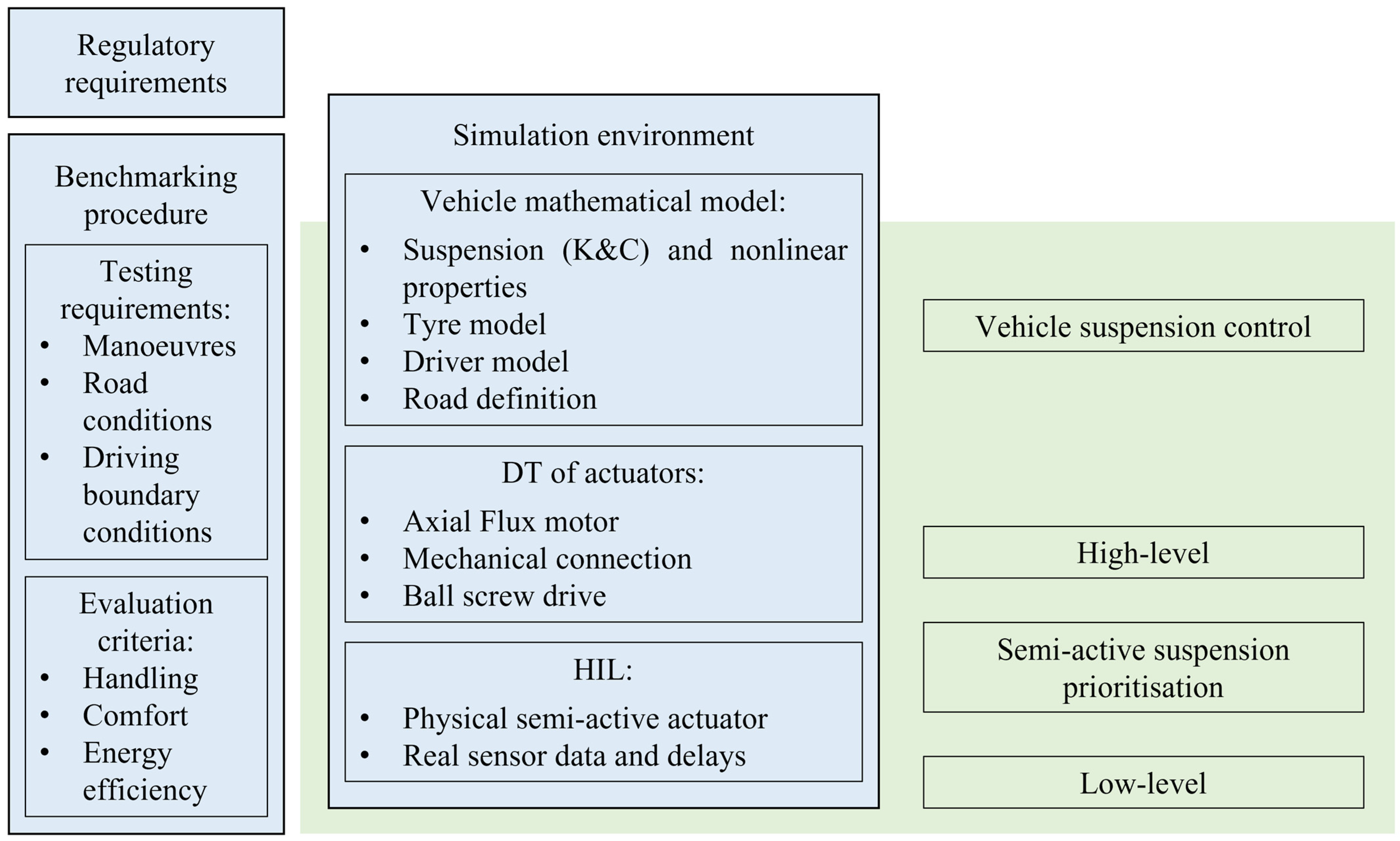
Below, we present a novel component development approach based on a simulation environment that incorporates DT, MIL, SIL, and HIL. The proposed component development approach addresses circular causality that arises when components must be developed before a complete system exists, such as a real vehicle in which that system will be installed, or when a control strategy needs to be developed before an actuator prototype is available.
The development approach is realised for the system described in
Section 3. We use a vehicle’s high-fidelity mathematical model, where a physical semi-active hydraulic actuator and all sensors are installed in HIL. An active electromechanical actuator is realised as a DT. The required signal filtering is performed to obtain the delay (from HIL), and the DT enables evaluation of the nonlinear actuators’ dynamics, which is not feasible with virtual control actions or by considering actuator dynamics via transfer functions. Additionally, the DT of the actuator is used to develop a low-level controller. For the proposed approach, all design steps (system identification, actuator design (including component selection), control strategy development, and testing) are performed in parallel and continuously improved until the required performance is achieved. The principal scheme for the simulation environment system is shown in
Figure 2.
During the initial investigation, regulatory requirements for the system under investigation should be identified; typically, they include functional safety and cybersecurity requirements. After that, a benchmark procedure should be created that includes a list of manoeuvres and evaluation criteria. Initial actuator requirements can be identified by conducting a primary investigation of the passive system in a simulation environment. In a simulation environment, only objective evaluation can be performed, and it is the main limiting factor of the proposed approach. However, recent investigations into different threshold identification methods provide a clear understanding of whether the driver or occupant will feel the difference.
The main advantage is that it enables parallel development of all necessary investigations for product development. In the first iteration, the system is simplified to the generation of an ideal force, without constraints on the actual actuator. Control algorithm selection can be performed in parallel. During the second iteration, the input signal used for control may be filtered, and actuators may be modelled as transfer functions. In the third iteration, the system actuator dynamics are included via the actuator’s DT; at this stage, the actuator nonlinearity is considered. The final stage: the existing semi-active actuator is installed in the test rig, and HIL tests have been performed using the digital twin of the EM actuator.
To perform the investigation, a simulation environment should be created that accurately replicates the testing conditions available on the proving ground. This includes modelling pavement selection, road roughness, irregularities, and artificial elements such as speed-reducing bumps.
A high-fidelity mathematical model of the sport utility vehicle has been realised in the IPG CarMaker 9.0.2 software, running in a co-simulation with MATLAB/Simulink R2019a. It is a modification of a widely used 14-degree-of-freedom (DOF) vehicle model. The Magic Formula 6.1 model is used for the tyre dynamics representation; it is parameterised based on experimental data. The model considers transient tyre behaviour, capturing lateral/longitudinal forces and self-aligning moment, including combined slip interactions, load and camber effects, and nonlinear saturation. At the first stage, vehicle subsystems, including steering and suspension, are parameterised using nonlinear curves and LUTs, featuring experimentally derived quantities such as suspension stiffness, damping, kinematics, and compliance (K&C). Later, the suspension actuators are replaced with DTs, and the physical ones are used in HIL.
In the MIL application, only IPG CarMaker and MATLAB/Simulink are used for the co-simulation interface. Both packages run simultaneously at a data exchange rate of 1000 Hz. In HIL scenarios, the model is transformed into a real-time application and loaded onto the dSPACE real-time target machine (ds1006) and the IPG CarMaker HIL software. Once the real-time simulation is initialised, the dSPACE ControlDesk 7.2 is utilised to exchange data between software and hardware components installed on the test rig. The same data exchange rate is used.
The entire vehicle model is validated using proving ground experimental data of Vaseur and Aalst [
43]. The main vehicle parameters are presented in
Table 1. Comprehensive information regarding the validation of the mathematical model is provided in the paper by Šabanovič et al. [
44].
4.1. DT of EM Actuator
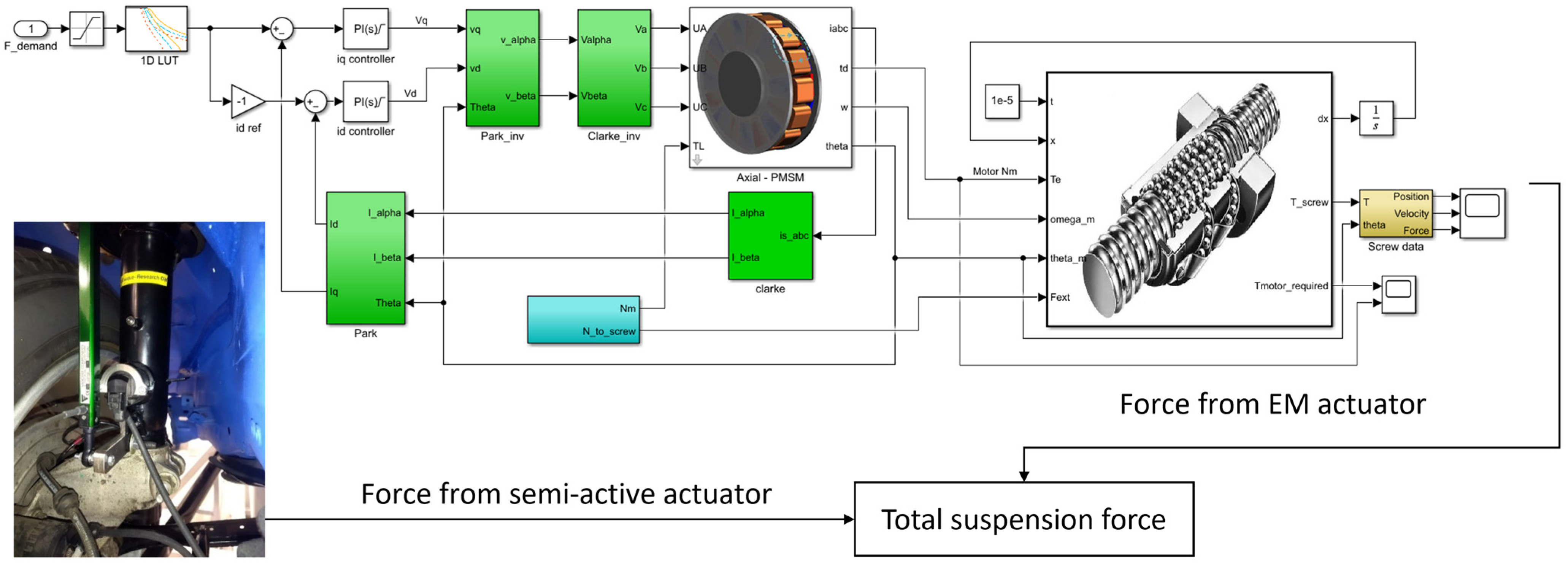
The DT of the actuator, in particular, should include both electrical and mechanical parameters, accounting for nonlinearities such as gear backlash. Additionally, sensors integrated into vehicles equipped with actuators are modelled, accounting for the noise they generate. The actuator design is shown in
Figure 3. It combines a physical semi-active actuator with a DT of an EM actuator and a low-level controller.
In the EM actuator, an axial-flux permanent-magnet motor is used, which is modelled as a symmetrical three-phase, smooth-air-gap machine with sinusoidally distributed windings. The model gets three-phase voltages and the load torque as inputs. The phase voltage equations for the three stator phases are as follows:
where
are the phase currents, and
are the phase magnetic fluxes.
To use the two-vector model, the phase voltages are transformed. First, a Clarke transformation is applied. A system of three variables reduces to two. The Clarke transform is applied as follows:
When the Clarke transformation is applied, the voltage equations are written as
where
are
and
axis currents;
are
and
axis magnetic fluxes.
After this, the Park’s transform is applied. It transforms the stationary reference frame in the
coordinate system (after the Clarke transform) to the synchronously rotating reference frame (dq frame):
where
and
are
and
axis voltages;
and
are
and
axis voltages;
is the rotor angular position.
In the dq frame, the voltage equations are
where
and
can be expressed as follows:
The electromagnetic torque produced by the motor is expressed as
For the actuators DT, four components were modelled: (i) position controller; (ii) axial-flux motor; (iii) gear; and (iv) ball screw drive. The model was developed using MATLAB/Simulink software.
The initial actuator comprises a gearbox and a ball screw, which convert the motor’s rotational motion into linear motion. The system equation of motion is as follows:
where
—stiffness and damping of the shaft;
—torques at gear and pinion;
—mesh force; and
—variable initial radii.
In operation, the centres of gears are moving because they are subject to rotational torques (). To determine gear location at any moment of time, displacement vectors are used. Meshing errors can occur during the manufacturing process of gear parts. With an increase in the mechanism’s service life, the number of faults is growing, backlashes are becoming wider, and the units’ flexibility is increasing. Thus, the development of a mathematical model of the gear and variations in the centre distance should be evaluated.
Centre distance depends on the accuracy of the manufacturing process. However, a certain deviation from the nominal size is inevitable.
When a gear train is loaded, the gears are displaced relative to each other, further increasing the variation in centre distance. As for the mechanism’s operating mode, bearing flexibility is increasing, leading to further changes in the centre distance. For example, if the initial centre distance is , in an operating gear train, it is equal to (time function).
The displacements of points 1 and 2 along a straight line, which is a tangent line to the circles of both gears, are calculated as follows:
The force acting on the mesh is obtained from the expression
where
is the damping coefficient; and
is the mesh stiffness determined by the method offered by Skrickij and Bogdevičius [
45]. It should be noted that the parameter is a time function.
The influence of the backlash is determined in this way:
Bearing force is found to be
where
i = 1, 2, 3, 4;
is the rate of penetration;
is the coefficient; and
is the restitution coefficient.
Axial displacements of gears are determined as
where
is the gravitational acceleration.
The state vector for the ball screw is
where
—ball screw angle [rad],
—ball screw angular velocity [rad/s],
—ball nut linear displacement [m], and
—ball nut linear velocity [m/s]. The backlash in the ball screw is considered as shown in Equation (25).
External forces applied to the ball screw drive are converted to equivalent screw torque:
where
—pitch and
—external force on the ball nut [N], received from IPG Carmaker.
4.2. High-Level and Low-Level Control
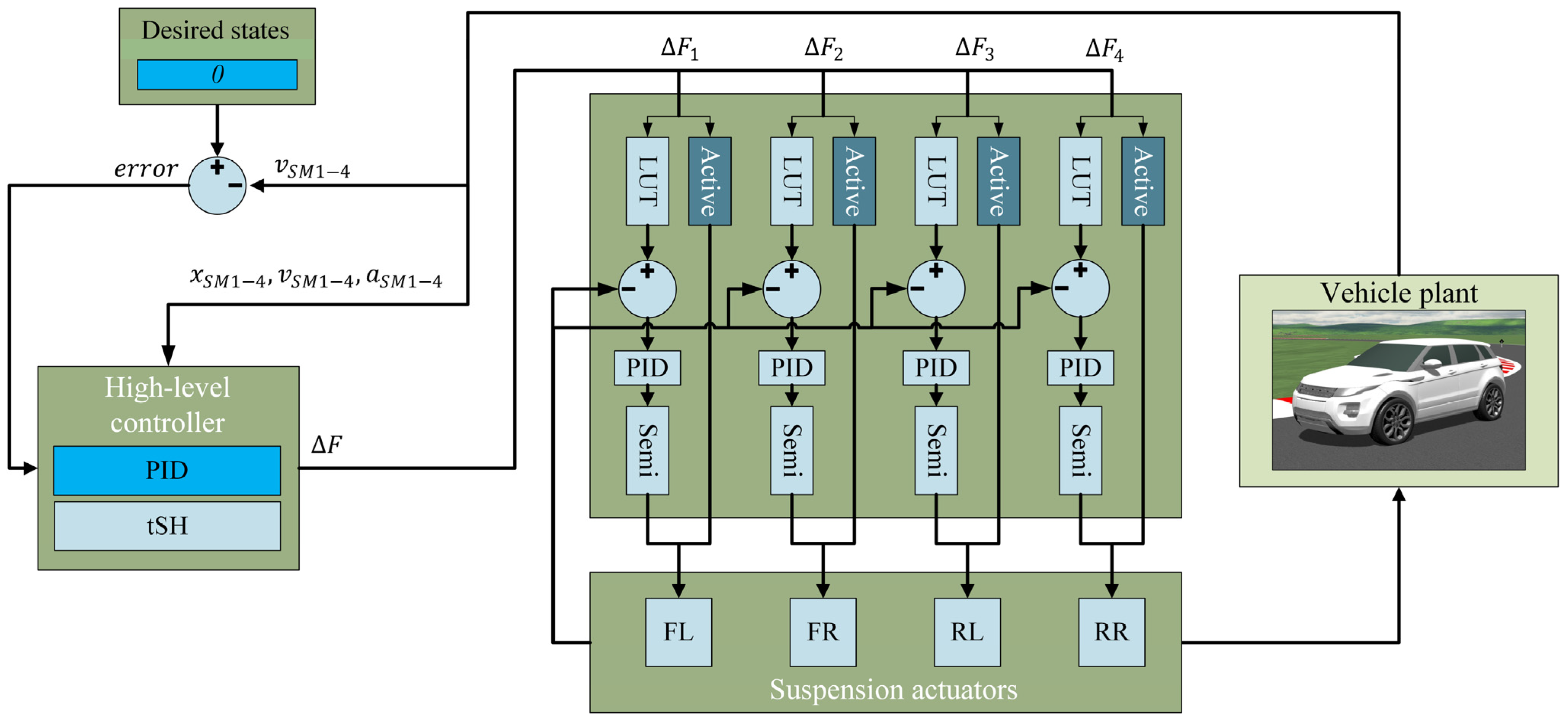
The whole control pipeline is presented in
Figure 4. As was mentioned above, the task of this paper is to address the comfort issue. The control algorithm was implemented to reduce the sprung mass velocities measured above the actuators’ placement, thereby minimising pitch and roll as well.
As a baseline algorithm, PID was used in this investigation. A typical vehicle is a mechanical system of order 2; for such a system, a PID controller is a perfect fit. The reference for such a system could be the sprung mass’s vertical velocity equal to zero; the gain for the proportional part would be velocity, for the integral part, displacement, and for the differential part, acceleration.
where
,
—gains, and
—errors between actual position, velocity, acceleration, and corresponding reference signals. The reference in each case is set to 0. The parameters used are shown in
Table 2.
We used the approach based on Triple Skyhook (tSH) proposed by [
46,
47]. This control method is derived for a quarter-car system. This controller requires three measured states: displacement (
), velocity (
) and acceleration (
). Dynamic equations are transformed into the Laplace scale, and from the sprung mass equation, the control law is derived:
The first member in Equation (2) is a low-pass and high-pass filter product together with the control gain:
where
—main control gain,
—low-pass cut-off (rad/s) for the actuator bandwidth modelling, and
—high-pass cut off (rad/s) to remove bias.
In classical representation, the tSH control law looks like this:
where
—sprung mass of the vehicle corner,
—damping gain, and
—stiffness gain. The controller parameters used are shown in
Table 3.
Motor control is performed using the field-oriented control (FOC) method. In the dq reference frame, the motor behaves like a DC motor, where the d-axis current controls the magnetic flux and the q-axis controls the torque; therefore, the main objective of FOC is to keep the d-axis current to 0 and the q-axis current to the set point value to extract the maximum torque from the available magnetic flux.
PI controllers are selected for the current control. The reference for the d-axis current is 0, and the reference for the q-axis control is given from the rotor position PI controller. Phase currents of the stator windings are measured, then they are transformed to the dq reference frame using the Clarke and Park transformations and given as feedback to their corresponding current PI controllers.
The outputs of the current controllers are the
and
voltages in the dq (rotating) reference frame. Then they are converted to phase voltages using first the inverse Park transformation (voltages in the rotating dq frame transformed to the stationary
frame):
For the Park and inverse Park transformations, the angle
of the magnetic field is needed. It is recalculated from the position of the rotor using this relationship:
. The rotor position can be measured directly using a sensor (encoders and resolvers are commonly used) or estimated from the motor model equations and measured phase currents. This method is called sensorless FOC.
Then
currents transform to
voltages, and then the inverse Clarke transformation is applied (
frame to the 3-phase voltages
):
The position control can be realised using a PID controller that receives rotor position feedback and directly feeds it to the dq current controllers. Alternatively, a PI position controller can be used in conjunction with a PI speed controller, which then feeds into the PI current controllers.
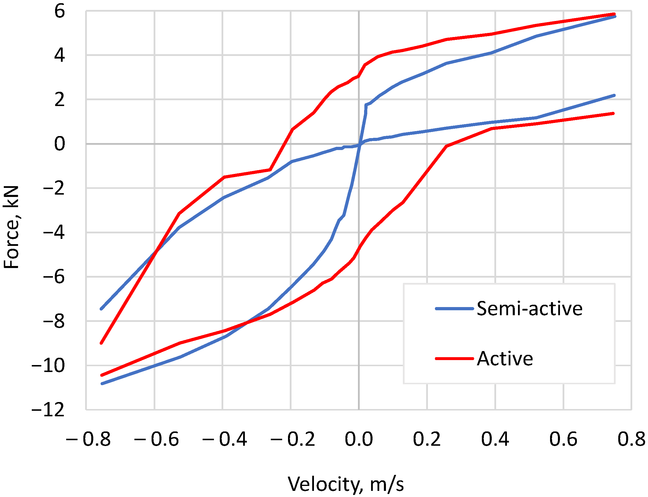
The forces calculated in Equations (33) and (34) represent the total control force demand. Priority is then given to the semi-active hydraulic actuator, which is controlled by adjusting the current from 0.4 A to 1.6 A to minimise energy consumption. A LUT is used where the input parameters are the force and relative velocity (difference between the sprung and unsprung masses). When a semi-active actuator cannot produce the required force, the active actuator supplies the remaining force; this is most noticeable at low relative velocities, where the semi-active actuator generates very little force (see
Figure 1). Note that regimes exist in which the semi-active and active actuators conflict—for example, when the relative velocity is negative but a positive force is required, or when the relative velocity is positive but a negative force is required (
Figure 1). If this occurs, an active actuator needs to produce all the required force plus an additional force to eliminate the negative effect of a semi-active actuator. In such instances, to save energy, the control current for the semi-active actuators is reduced to 0.4 A.
4.3. HIL Testing
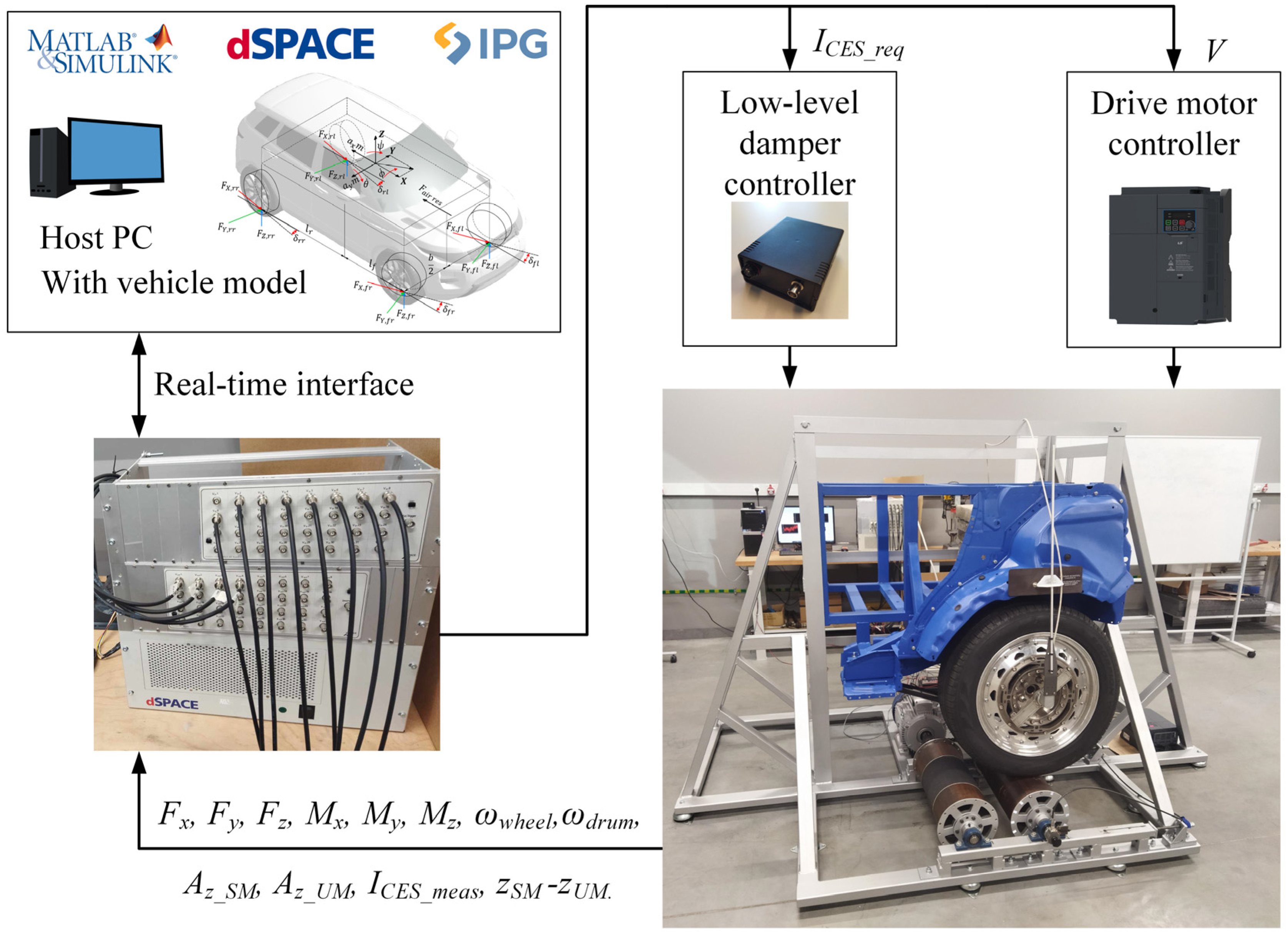
A vehicle quarter-car test rig (
Figure 5) is employed to develop and test vehicle suspension hybrid actuators. The test rig features actual suspension/chassis components with realistic mass and inertial properties. It is equipped with a semi-active hydraulic actuator. A rotating drum represents the road, and additional objects or bumps are attached to it to introduce road irregularities. The purpose is to test the EM actuators’ performance and control algorithm in real time and analyse how noise and delays affect overall control effectiveness and comfort at the full-vehicle scale.
The test rig is a hardware part of the developed HIL architecture. The dSPACE real-time target machine is used to integrate the actual hardware with the validated vehicle mathematical model. A real-time target system is utilised to acquire key experimental measurements. The wheel force transducer records tyre forces and torques, along with the wheel’s angular velocity. To support suspension control, measurements include the vertical accelerations of the sprung and unsprung masses, the suspension stroke, sprung mass displacement, and the current supplied to the damper valve.
During testing, two approaches were investigated: MIL and HIL. In the MIL method, the change in vertical force caused by driving over a road bump is measured. This measurement is fed to the vehicle’s mathematical model in real time as an external force acting on all four wheels. In this way, synchronisation between the mathematical model and the test bench is achieved. All other vehicle state parameters required for control are obtained from the mathematical model. The purpose of these open-loop tests is to verify the correctness of the input and output signals, and to generate a reference performance against which full closed-loop tests will be compared. During the test, both semi-active and active suspension control forces are measured; however, they are not returned to the test bench.
The HIL method is realised in the full closed-loop experiment. The actual semi-active suspension force depends on the measured velocity difference and the generated valve control current, which is computed within the mathematical model and transmitted to the valve. The objective of these closed-loop tests is to validate the actual semi-active suspension force against the reference produced by the control algorithm. Since an active damper is not available in the test rig, the active suspension force is modelled and applied at all four corners of the vehicle. In this way, vertical motion is better controlled, ensuring passenger comfort.
To ensure that the mathematical model receives correct signals from the quarter-car test rig, a tyre force recalculation scheme was developed and presented in Kojis et al. [
48]. The recalculation scheme uses outputs from the validated MF 6.1 tyre mathematical model and measurements from the wheel force transducer. Simulations and experiments with the same boundary conditions were performed, and a database with look-up tables used for force recalculation was created. Hence, the measurements from the quarter-car test rig are scaled accordingly, and the mathematical model receives corrected data. The scheme includes the recalculation of lateral, longitudinal, and vertical forces. Therefore, data exchange between the test rig and the vehicle mathematical model is possible, and evaluation at full-vehicle scale is viable.
Compatibility between software packages is ensured. For environment simulation, vehicle dynamics, and perception sensors, IPG CarMaker software is used. High-level, middle-level and low-level controllers, as well as DTs for actuators, are implemented in MATLAB/Simulink. All models employed for the DTs meet the requirements of MIL systems, with the vehicle model capable of real-time performance for subsequent HIL simulation. The algorithms used must also operate in real time on the target hardware without modification (i.e., meet SIL requirements). The system is designed to allow actuators’ DTs to be replaced by physical ones in the future. While control algorithms need to be developed before manufacturing the actuators, the DTs created at this stage are suitable for algorithm development, tuning, and testing—with final tuning performed within the HIL environment.
5. Results
As mentioned above, only comfort, which is very important for automated driving, was considered, with the RMS of vertical acceleration as the key performance indicator.
First, simulations with a full vehicle model featuring passive suspension were conducted on sinusoidal road excitations with varying frequency and driving velocity, and a constant amplitude of 0.01 m. Vehicle travel speeds ranged from 20 to 130 km/h to target primary and secondary rides. Excitation frequency was investigated up to 15 Hz since humans are most sensitive to frequencies in the range of 4–8 Hz, and above 15 Hz, noise, vibration, and harshness (NVH) effects take over. At speeds of 20, 50, 70, 90, 110, and 130 km/h, 90 runs were simulated. Road irregularities were selected to produce periodic excitation in the range from 1 to 15 Hz, with a 1 Hz step. For each frequency, the conditions that produced the largest vertical acceleration were selected (for example, 5 Hz excitation with a velocity of 50 km/h, or 2 Hz excitation with a velocity of 20 km/h, and so on). The worst-case results for the passive suspension are shown in
Figure 6.
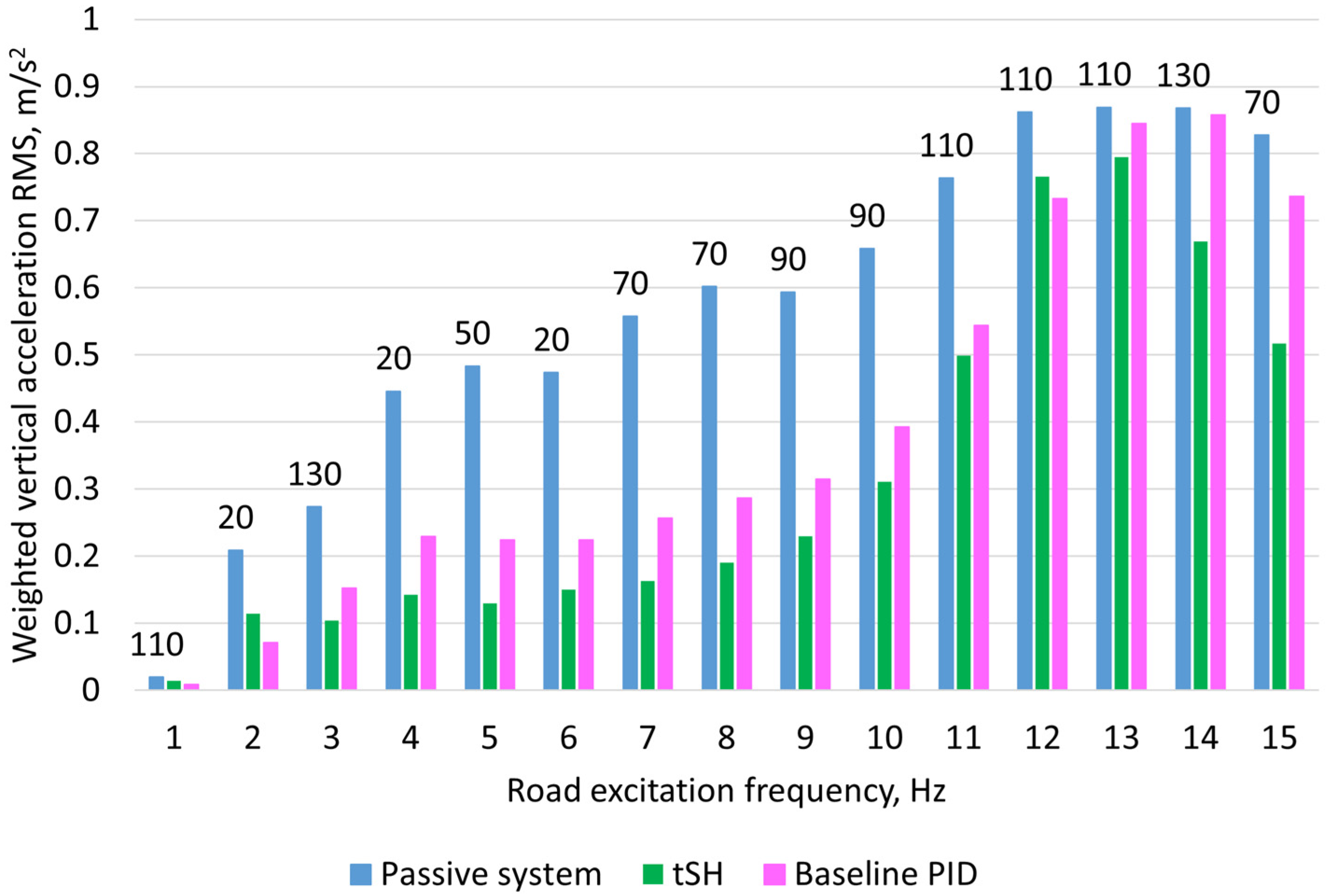
In the same scenarios where the highest vertical accelerations were registered with passive suspension, baseline-based PID and tSH algorithms are tested. The RMS values of the sprung mass vertical acceleration are shown in
Figure 6.
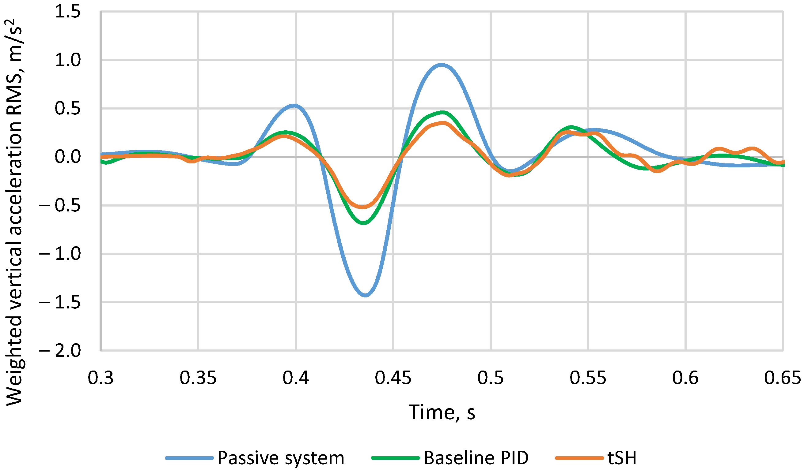
The proposed approach based on HIL and DT is investigated. Both controllers are benchmarked against the passive suspension system. Weighted vertical acceleration root mean square (RMS) value based on ISO 2631 [
49] Wk filter approximation is chosen as the main performance metric. The results summary is shown in
Table 4 and
Figure 7.
Comparing the results in
Figure 7, the tSH algorithm outperforms the baseline PID algorithm. This again proves the efficiency of the proposed DT approach for the development of ground-vehicle chassis actuators.
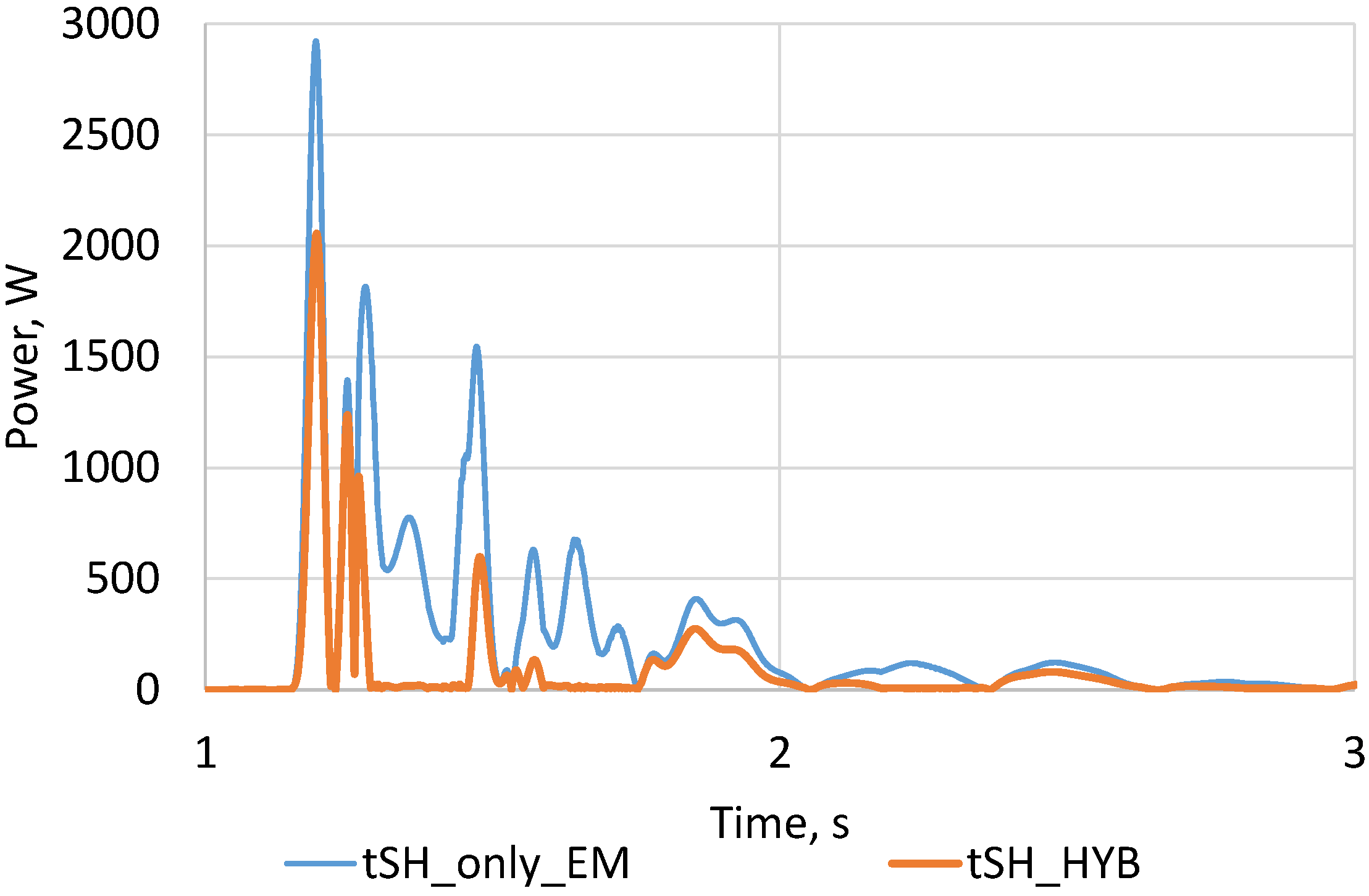
The proposed control method outperforms the baseline. Neither method is computationally intense. Since the registered turnaround time in the HIL simulations is about an order of magnitude lower than the sampling time for both algorithms. However, the control algorithm is not the main question of this paper. This paper presents a novel design framework that accelerates the traditional V-model development lifecycle by enabling DTs and HIL testing. A hybrid suspension architecture combining a continuously controlled hydraulic damper with an auxiliary electromechanical actuator has been proposed. Power consumption has been compared between two configurations. The first configuration includes a single electromechanical actuator. The second configuration includes a continuously controlled hydraulic actuator in parallel with an electromechanical actuator.
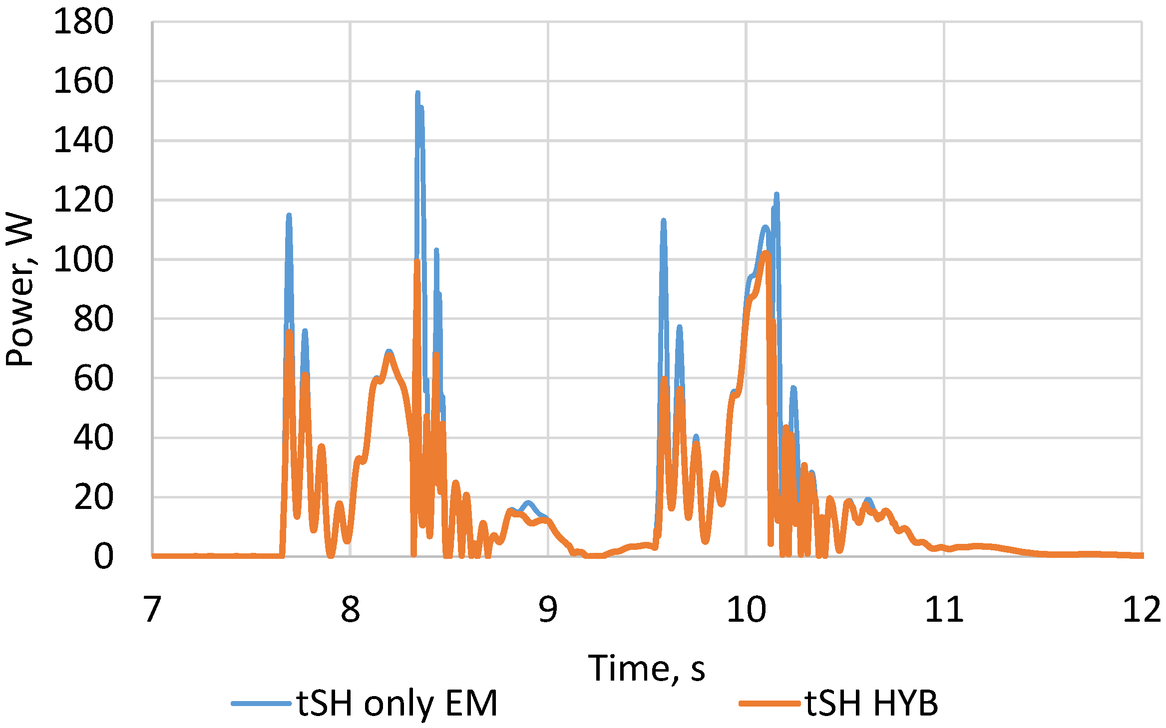
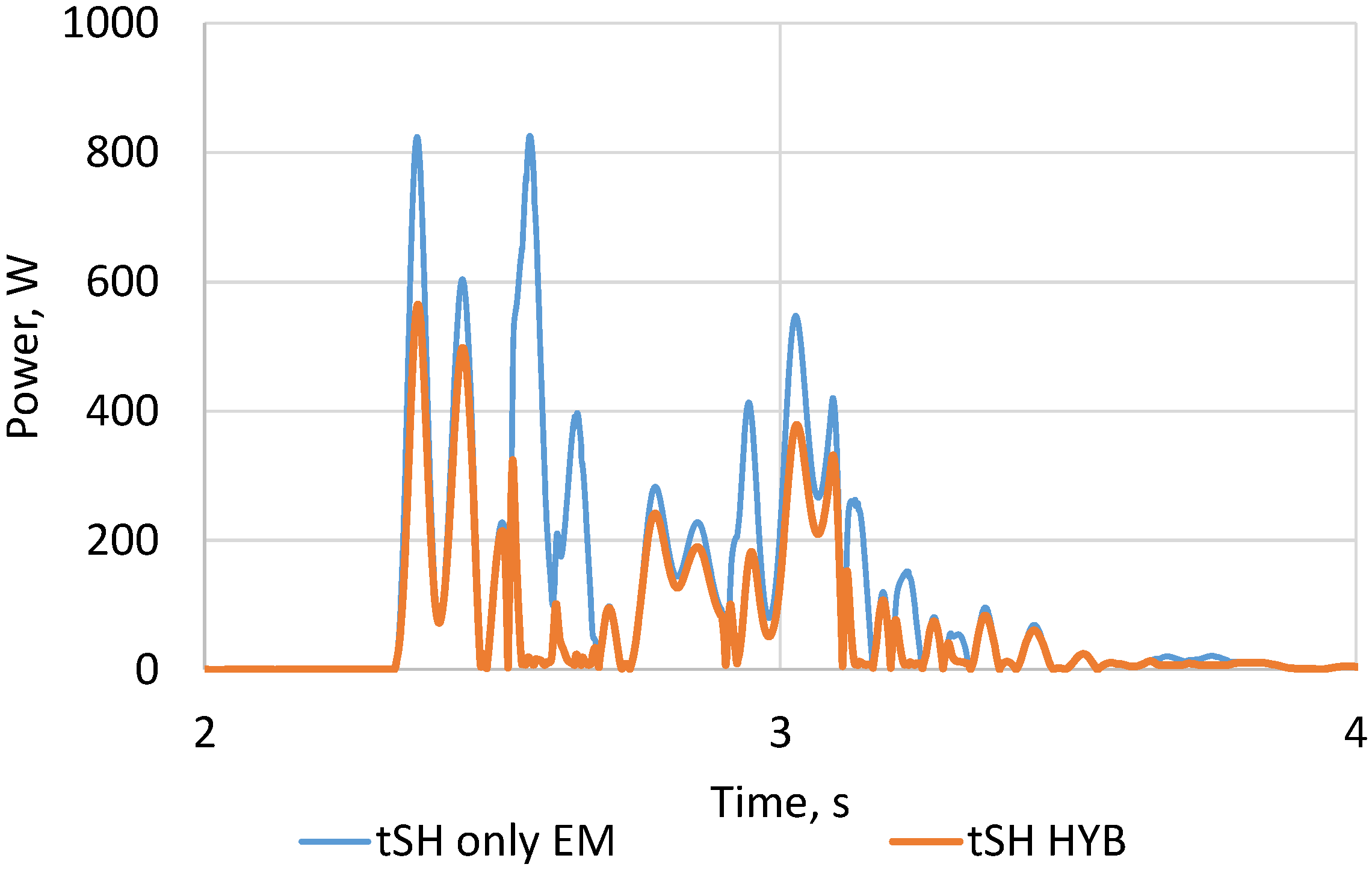
Results are presented in
Figure 8,
Figure 9 and
Figure 10. It was found that the system uses about 18% less energy in the low suspension stroke velocity case (up to 0.2 m/s) (
Figure 8), more than 43% less energy in the medium suspension stroke velocity case (up to 0.5 m/s) (
Figure 9), and more than 61% less energy in the high suspension stroke velocity case (up to 1.0 m/s) (
Figure 10). Energy reduction is related to semi-active actuator prioritisation in high-stroke scenarios, where it can produce much higher forces than in low-stroke scenarios. Hence, a higher semi-active contribution unloads the demand for active force, reducing energy consumption.
The results demonstrate that the hybrid system achieves lower energy consumption than purely electromechanical suspensions while overcoming the bandwidth limitations of conventional hydraulic active suspensions.
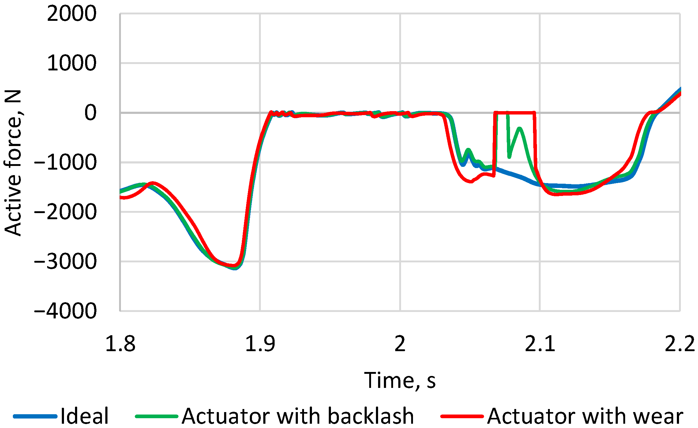
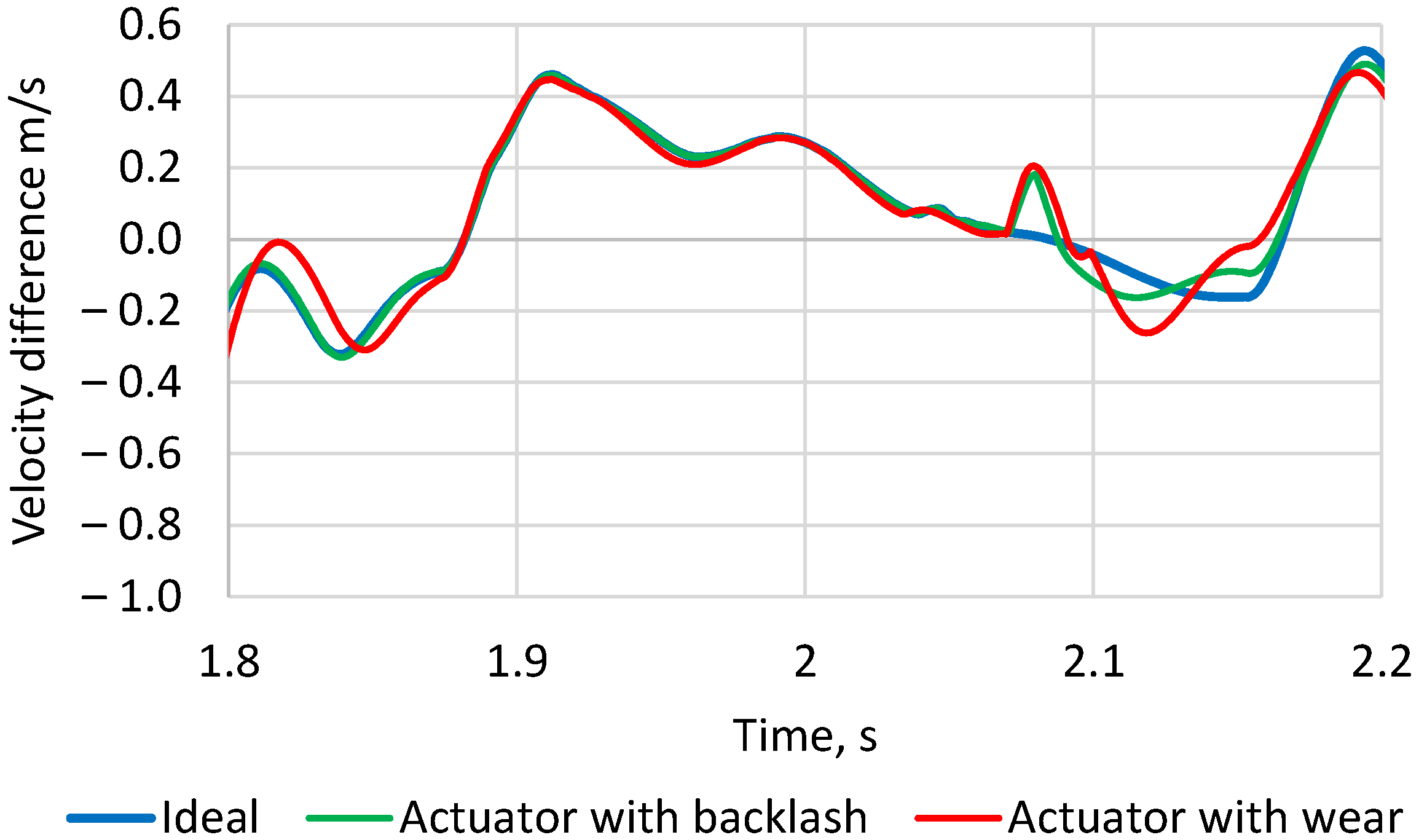
An additional investigation was performed to evaluate the effect of the backlash. The estimated actuator system backlash consists of 50 in gear centre distance variation, 50 in gear couple meshing backlash, and 30 in ball screw drive. As an extreme measure, the backlashes were increased by a factor of 10 to represent possible actuator wear.
In the scenario in which the vehicle passed the trapezoidal speed bump at 40 km/h, no disturbing deviations were recorded. The tSH algorithm was able to control the suspension like that without backlash. As shown in
Figure 11, due to backlash, the EM actuator is unable to produce force in some instances. Comparing backlash and wear cases, the nonlinearity is more noticeable because the actuator has to overcome it to produce force. This results in a higher time span with no active force.
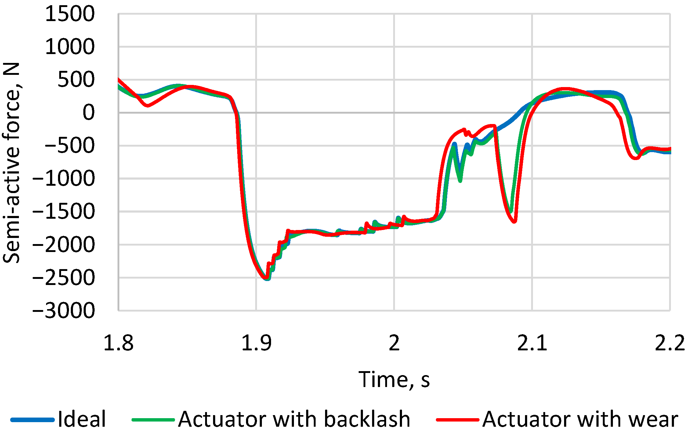
From
Figure 12, it is seen that the backlash in the EM actuator alters the semi-active force curve. While the EM actuator is unable to produce any force, the semi-active actuators step in and try to compensate for the lack of control force.
The increase in semi-active force also correlates with higher stroke velocity (
Figure 13). Since the backlash reduces EM actuator output, the stroke velocity increases, and the semi-active suspension force contribution is higher.
Even though the tSH algorithm was able to control the suspension during backlash and actuator wear, the main comfort metric degraded. In the ideal case, the weighted vertical acceleration RMS value is the lowest—0.193 m/s
2, with backlash—0.197 m/s
2, and with wear—0.203 m/s
2. This decrease is relatively small, and, based on difference thresholds Gräbe et al. [
50], it can be stated that passengers will not feel the difference.
6. Discussion and Conclusions
Over the last decade, the time-to-market in the automotive industry has been drastically reduced. For researchers and engineers, new development lifecycle frameworks are required to increase productivity. This paper presents a novel design framework that accelerates the traditional V-model development lifecycle by enabling system identification, actuator design (including component selection), control strategy development, and testing to be performed in parallel using high-fidelity models supplemented with DTs in HIL testing.
As a case study, the design of active suspension actuators to address comfort shortfalls that hinder automated driving has been selected. A hybrid suspension architecture combining a continuously controlled hydraulic damper with an auxiliary electromechanical actuator has been proposed.
Control is implemented using the Triple Skyhook algorithm and benchmarked against a baseline strategy. From the perspective of vehicle comfort, it was improved by over 60% compared to a passive system. Additionally, it was demonstrated that the hybrid actuation system consumes less energy than purely electromechanical suspensions. In the performed test, energy consumption was reduced by 18–61%.
Incorporation of DT enabled consideration of actuators’ nonlinearity, arising from gear centre distance variation, backlashes in gear meshing, and ball screw drive. A sensitivity analysis of how these nonlinearities impact system dynamics has been performed. It was shown that, in this hybrid configuration, the free play of the EM actuator is compensated by an increased semi-active force contribution. The results confirm that both minimal backlashes and component wear negatively impact system dynamics. However, the selected control method demonstrated robustness to these nonlinearities. Comfort KPI demonstrated performance degradation; however, the value is below the difference thresholds, which means occupants will not feel the difference even when driving a vehicle with worn actuators.