1. Introduction
The braking system of motor vehicles is essential for road safety and vehicle performance. The increased risk of accidents is strongly influenced by the reliability of the braking system, reported by the deceleration time [
1]. From a technical point of view, the braking system transforms the kinetic energy of a moving vehicle into heat through the friction between the brake pads and discs (or drums)—allowing for controlled deceleration or complete stopping. The control of the braking process is defined by the system’s ability to provide sufficient braking force, accompanied by good response and stability under variable conditions (load, speed, road friction). Recent research highlights additional important aspects. Ilie et al. [
2] demonstrated that brake pads and discs directly degrade brake efficiency over time, potentially increasing brake distances in real traffic conditions. Furthermore, another 2024 study on brake disc materials indicated that the choice of material (e.g., gray cast iron) significantly affects the durability and thermal performance of brake components, which in turn influences safety and functionality [
3]. Brake assist, electronic brake force distribution and designs optimized for heat dissipation and repeated use—especially in high-performance or heavy-duty vehicles—are increasingly present in modern braking systems [
4]. Its design, material properties and maintenance directly influence a vehicle’s ability to stop in time, maintain control in the event of emergency braking and ensure the safety of passengers and other road users [
5].
The concept of brake-by-wire (BBW) systems was first introduced by Goodyear in 1979 and later successfully demonstrated by Lorrel three years later [
6]. Based on the different control strategies and regulatory requirements for braking force, BBW systems can be mainly classified into electro-hydraulic brake systems (EHB) operated by servomotors, EHB systems using high-pressure accumulators and electro-mechanical brake systems (EMB). In the early 1980s, EHB systems were mainly based on servomotor drive. In the 1990s, development shifted to EHB systems using high-pressure accumulators, and in the last two decades, EMB systems have become the predominant technology in BBW applications [
7,
8,
9]. A conventional hydraulic braking system and a BBW system differ fundamentally in their operation and capabilities. On the one hand, in a conventional hydraulic system, the driver’s command is transmitted mechanically through the brake fluid, generating braking force through hydraulic pressure in the brake lines, with natural pedal feedback. On the other hand, BBW systems use electronic signals from sensors to actuators, producing braking force through electro-hydraulic or electro-mechanical means, while providing electronically simulated pedal feedback [
10]. Conventional systems limit and manage the distribution of braking force through mechanical or hydraulic valves, while BBW systems allow for dynamic, wheel-specific control using advanced electronic brake distribution (EBD). Another aspect that differentiates them is that anti-lock braking system (ABS) and electronic stability programs (ESP) in conventional systems require separate, integrated units, while in BBW these functions are incorporated directly into the electronic control unit (ECU) of the system. Last but not least, regenerative braking is not feasible in traditional hydraulic systems, but is possible in BBW systems, especially in electric and hybrid vehicles [
11]. It is also important to note that the braking response in BBW systems is faster and more precise due to digital control, compared to the slightly slower response of hydraulic systems, which depends on pressure buildup. BBW systems use electronic redundancy with backup power supplies, while redundancy in classic systems relies on separate hydraulic circuits. Customization is limited in hydraulic systems, while BBW allows adjustable driving modes, such as comfort or sport. A final aspect that can be mentioned is that integration with autonomous driving technologies, including automatic emergency braking and adaptive pilot, is inherently supported by BBW systems, while it remains limited in traditional hydraulic systems. Hydraulic systems require periodic fluid replacement and component checks, while BBW systems reduce mechanical maintenance but require regular electronic diagnostics [
12].
Recent advances in x-by-wire vehicle technologies increasingly rely on the integration of multiple electronically controlled subsystems and distributed control architectures, as demonstrated by recent work on multi-agent and game-theory-based coordination strategies for vehicle stability enhancement. However, despite these developments, the systematic identification and prioritization of failure modes in such complex architectures remain insufficiently addressed [
13].
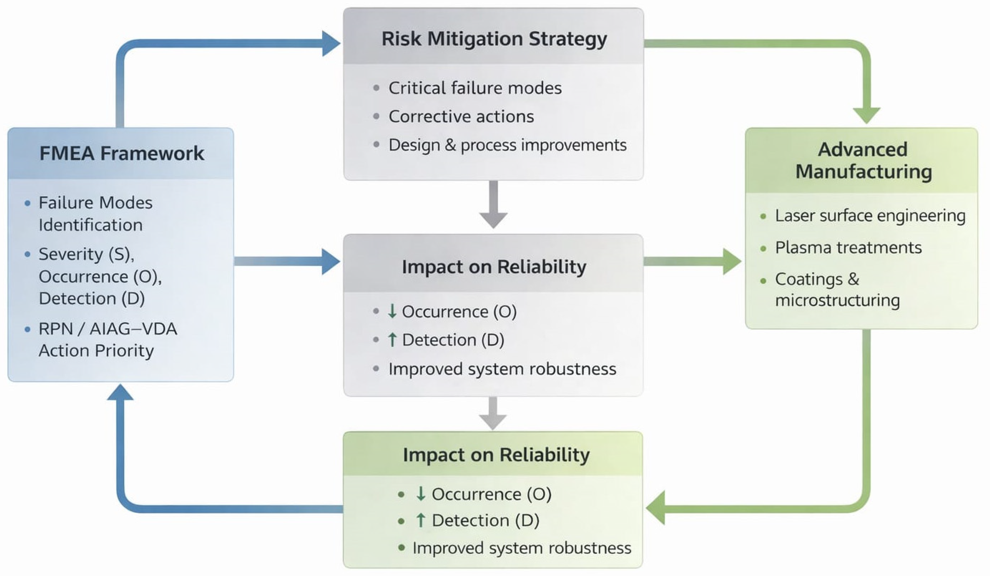
In this context, ensuring the reliability and safety of BBW architectures requires not only robust system design but also consistent and transparent methodologies for identifying, prioritizing, and mitigating potential failure modes. Failure Modes and Effects Analysis (FMEA) remain one of the most widely used tools for this purpose. However, the transition from the traditional Risk Priority Number (RPN) approach to the AIAG–VDA Action Priority (AP) framework has introduced new challenges in terms of interpretation, consistency, and practical implementation, particularly for complex multi-architecture systems such as EHB and EMB. While previous studies have largely focused either on system-level analyses or on specific subsystem failures, a structured comparative evaluation of EHB and EMB architectures using both RPN and AIAG–VDA methodologies remains limited. Moreover, the link between system-level reliability assessment and emerging manufacturing technologies is rarely addressed, despite their growing importance in the development of next-generation automotive systems.
Despite the extensive use of FMEA in automotive safety analysis, existing studies typically focus either on single-system evaluations or on isolated applications of RPN or AIAG–VDA methodologies. A systematic comparison of these two approaches applied to identical failure modes within different brake-by-wire architectures remains limited. Furthermore, the interaction between reliability assessment and emerging manufacturing technologies is rarely addressed, although material-level improvements play a critical role in mitigating failure mechanisms in modern systems. In addition, the rapid development of x-by-wire technologies in modern vehicles, including steer-by-wire and brake-by-wire systems, highlights the need for robust and transparent risk assessment methodologies capable of supporting increasingly complex, software-driven, safety-critical architectures.
In this work, a comparative FMEA framework is developed for EHB and EMB architectures, integrating both RPN and AIAG–VDA Action Priority approaches within a unified system-level analysis. The objective is not only to compare architectures but also to evaluate how different risk assessment methodologies influence prioritization outcomes for identical failure modes. The study is conducted under clearly defined system boundaries corresponding to the braking function at the item-definition level (ISO 26262 [
1]), considering representative operating conditions and failure mechanisms relevant to brake-by-wire systems. In addition to methodological comparison, the work explores the role of advanced manufacturing strategies—particularly laser and plasma-based surface engineering—in mitigating failure mechanisms. By linking degradation processes to material and surface modifications, the study provides a first step toward integrating reliability-driven design with manufacturing-informed optimization. To the best of the authors’ knowledge, this is the first study that explicitly integrates AIAG–VDA Action Priority-based FMEA with manufacturing-driven mitigation strategies in brake-by-wire architectures.
2. Electro-Hydraulic (EHB) vs. Electro-Mechanical (EMB) Braking Systems
The EHB and EMB represent the two major braking systems, which are the two technological directions towards brake-by-wire architectures in modern vehicles [
14]. As automakers move towards electrification, automation, and integrated chassis control, the ability to precisely modulate braking forces through fully electronic actuation is becoming increasingly important [
15]. Although both EHB and EMB replace traditional mechanical pedal-brake linkages with electronically controlled actuation, their structural principles and performance characteristics differ significantly. This section provides a comparative analysis of EHB and EMB systems, highlighting their operating principles, advantages, limitations, and suitability for next-generation vehicles [
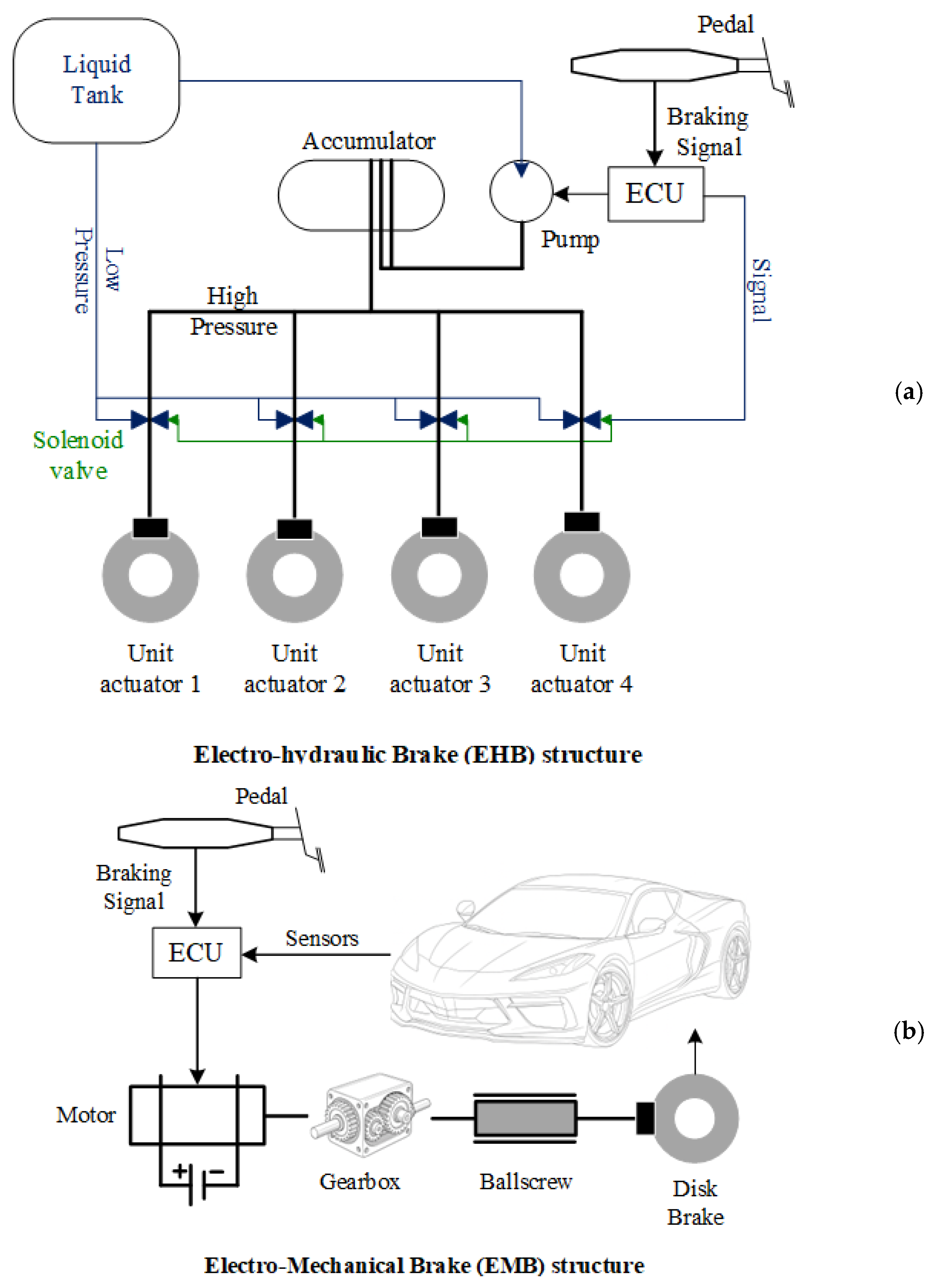
16]. In
Figure 1 (a—EHB and b—EMB, respectively) the main characteristics of the two systems used in the models analyzed later are highlighted. Considering the operating principles, EHB systems use electronic control signals to regulate the hydraulic pressure distributed to the brake calipers. The driver’s action on the pedal is interpreted by sensors and processed by an ECU, which commands pumps, solenoid valves, and accumulators to generate and modulate the hydraulic fluid pressure.
At the same time, the EMB system eliminates hydraulic transmissions. Each wheel is equipped with a dedicated electric motor or an electromechanical actuator (e.g., a screw-driven wedge actuator) that directly clamps the brake pads to the disc [
17]. This work presents a conceptual and comparative FMEA of EHB and EMB architectures. The objective is not to analyze a single braking system implementation, but to identify, compare, and evaluate architecture-specific failure modes and associated risks in order to highlight their respective reliability and safety characteristics. Another key aspect of these braking architectures concerns their performance characteristics, such as response time. Here, EHB systems reduce actuation delays compared to traditional hydraulic brakes; however, they still rely on the accumulation and release of fluid pressure, which inherently limits their dynamic response. On the other hand, EMB systems achieve millisecond response times, as their electric actuators act directly on the brake pads, providing highly dynamic control—an advantage particularly relevant for autonomous driving functions and advanced stability control systems. We cannot overlook the fact that EMB technology offers superior controllability, allowing independent wheel-level interventions, such as torque vectoring. Although EHB systems allow precise modulation of hydraulic pressure, their performance remains limited by the nonlinear hydraulic behavior and the compressibility of the fluid [
18,
19]. When evaluating these systems through failure modes and effects analysis, safety and reliability emerge as critical differentiators. EHB architecture possesses an intrinsic advantage: in the event of an electronic control failure, backup hydraulic mechanisms can typically maintain a minimum level of braking functionality. This inherent redundancy enhances system robustness and has been a key factor behind the widespread industrial acceptance of EHB technology. In contrast, EMB systems do not benefit from passive mechanical backup modes. Their safety performance depends entirely on electrical and electronic redundancies, including dual-power architectures, redundant control units, and fault-tolerant actuator configurations. Although recent advances in automotive functional safety—particularly those guided by ISO 26262—have significantly improved the reliability of EMB solutions, achieving consistent operational behavior under failure conditions remains a major engineering challenge [
20,
21].
In accordance with ISO 26262, the analysis presented in this paper is conducted at the level of the item definition, where the considered item is the
vehicle braking function. The system boundaries are defined to span from the generation of a braking request to the realization of braking torque at the wheel actuators. Within this framework, perception sensors are included only as boundary input elements that may provide external or driver-related signals influencing the braking demand. The scope of the analysis does not extend to ADAS or AEB functionalities, and no assessment of perception algorithms, object detection performance, or decision-making logic is performed. Sensor-related aspects are considered solely to identify functional interfaces and to evaluate how potential input-level failures may propagate to the braking-by-wire system. This approach ensures a complete yet clearly delimited system-level view of the braking function, consistent with ISO 26262 conceptual and hazard analysis principles. A mature intermediate step towards fully electronic braking is electro-hydraulic braking, which offers improved performance while retaining hydraulic safety mechanisms. Electromechanical braking represents the ultimate brake-by-wire solution, offering superior response, control and integration potential, albeit at the cost of higher redundancy requirements and emerging maturity. Based on this comparison, a synthetic evaluation can be presented in the form of either a comparative table (
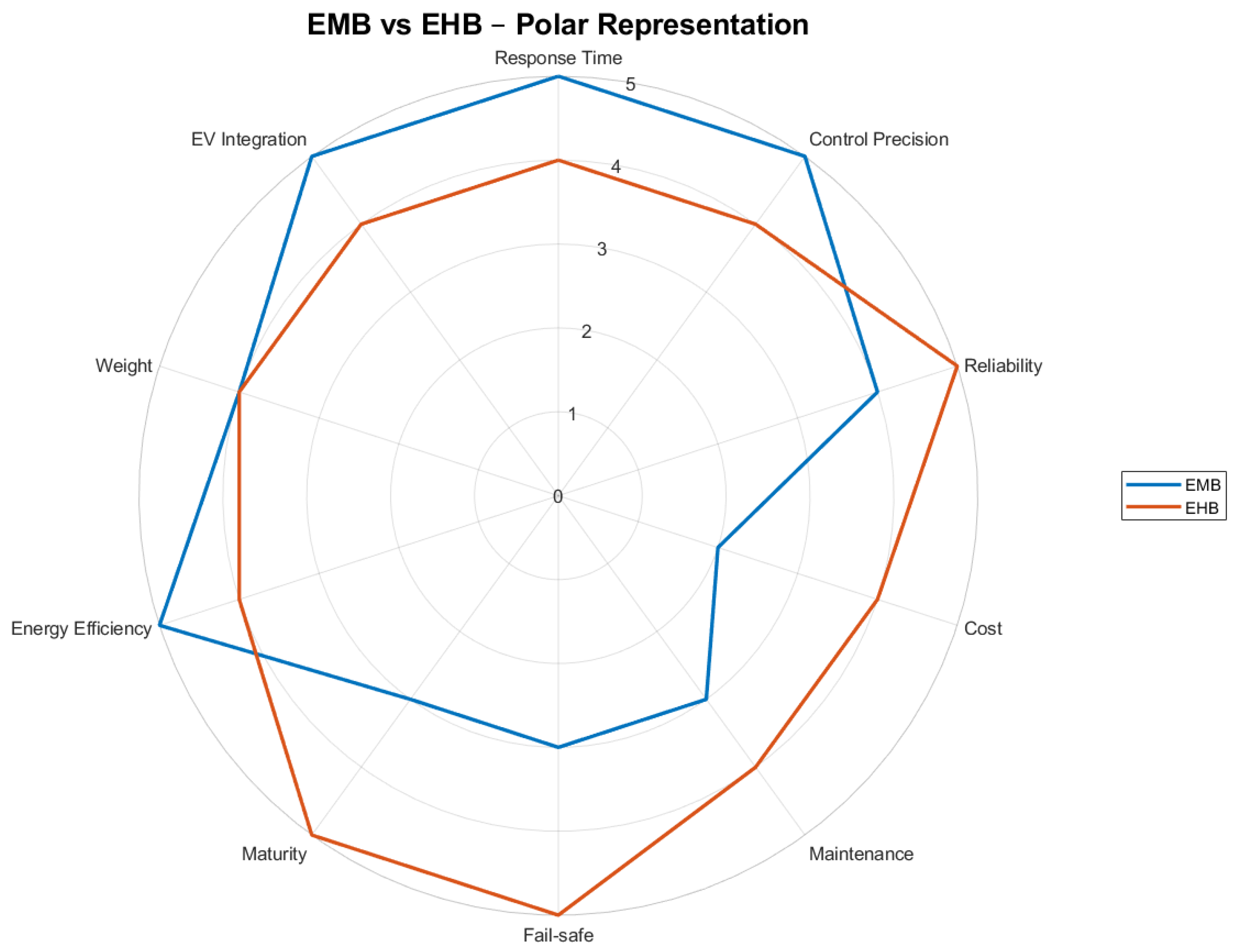
Table 1) or a radar representation (
Figure 2). These representations assign each system a score from 1 (lowest performance) to 5 (highest performance), based on the knowledge and operational experience accumulated over the past decades by major automotive manufacturers that have implemented these technologies. To enable a structured comparison between EHB and EMB architectures, a multi-criteria evaluation framework was defined. Each architecture was assessed using predefined performance indicators, including reliability, response time, system complexity, maintenance requirements, and fault tolerance. A discrete scoring scale from 1 to 5 was adopted, where each score corresponds to explicitly defined performance levels. The scoring was based on system characteristics reported in the literature and engineering considerations related to brake-by-wire architectures.
Comparative evaluation employs an ordinal five-level scale to represent increasing performance or favorability of the analyzed characteristics, consistent with structured rating approaches widely used in engineering risk assessment and multi-criteria decision analysis. A score of 2 indicates low performance, corresponding to below-average capability with notable limitations or constraints affecting system operation. A score of 3 represents moderate performance, reflecting acceptable or average characteristics without significant advantages or disadvantages. A score of 4 denotes high performance, indicating favorable system behavior with only minor limitations. A score of 5 corresponds to very high or excellent performance, representing superior capability with minimal limitations and highly desirable characteristics. Such ordinal scales enable consistent comparison of system attributes while preserving the qualitative interpretation of engineering judgments, as commonly adopted in automotive FMEA practice and multi-criteria evaluation methods.
The present analysis is limited to the brake-by-wire actuation architecture and its direct control inputs (e.g., pedal request and actuator control). Higher-level perception systems and ADAS functions such as Automatic Emergency Braking (AEB) or Adaptive Cruise Control (ACC) are considered external to the system boundary and are therefore not included in the FMEA. We can conclude that EHB systems remain a practical and reliable braking solution, benefiting from decades of hydraulic brake technology while offering improved control through electronic modulation. Their hybrid nature, however, limits their suitability for future vehicle architectures that require fully independent, high-bandwidth brake control. On the other hand, EMB systems, by eliminating hydraulics, offer responsiveness, modularity, and integration potential needed for next-generation electric and autonomous vehicles. Their adoption is accelerating, but widespread implementation requires continued advances in actuator reliability, power redundancy, and cost optimization.
It should be noted that the present comparison is based on representative architectures and typical operating conditions derived from literature and engineering practice. While the analysis captures the main functional and structural differences between EHB and EMB systems, the proposed framework is intended to be transferable to other x-by-wire systems, provided that system-specific failure modes and evaluation criteria are appropriately defined. This ensures that the methodological conclusions remain generalizable beyond the specific case study considered.
3. Results: Failure Modes and Effects Analysis of the BBW System
The FMEA is a fundamental analytical tool widely used in the automotive industry, supporting the systematic identification, evaluation and mitigation of potential failure modes throughout the product life cycle [
1]. With the increasing complexity of vehicle equipment, especially with the integration of ADAS, brake-by-wire technologies and electrified powertrains, FMEA provides a structured methodology for assessing risks based on severity, occurrence and detection (identified by values from 1 to 10), ultimately prioritizing failure modes according to RPN or AP [
22]. FMEA significantly contributes to improving safety, reliability and regulatory compliance by enabling cross-functional teams to trace causal chains, evaluate system interactions and propose specific design or process controls. By its dynamic and iterative nature, FMEA represents an indispensable component of modern quality management in the automotive industry, ensuring that engineering decisions reflect real-world operating conditions and evolving standards [
23].
The selected set of failure modes is representative rather than exhaustive. It was defined to ensure coverage of the main functional risks associated with brake-by-wire systems, including mechanical degradation, thermal effects, and control-related failures.
The selection is based on literature review, engineering knowledge of braking systems, and typical failure mechanisms observed in electromechanical architectures. While the inclusion of additional failure modes may refine system-specific prioritization, it would not alter the methodological conclusions regarding the comparison between RPN and AP approaches. In Ref. [
24] an overview was introduced that improved FMEA frameworks incorporating uncertainty handling provide a stronger basis for decision-making and risk mitigation, underscoring the need for further research and wider industrial adoption.
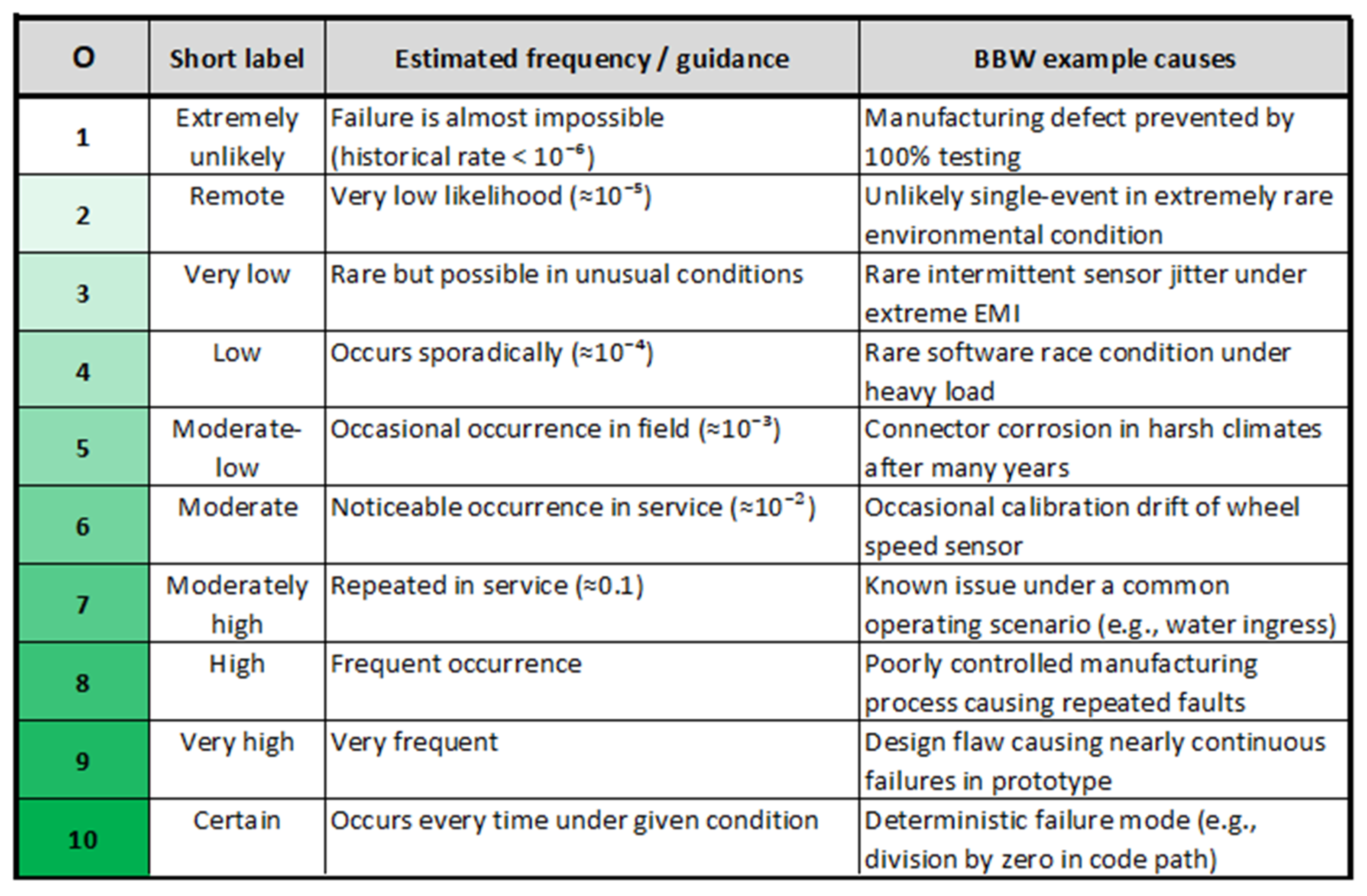
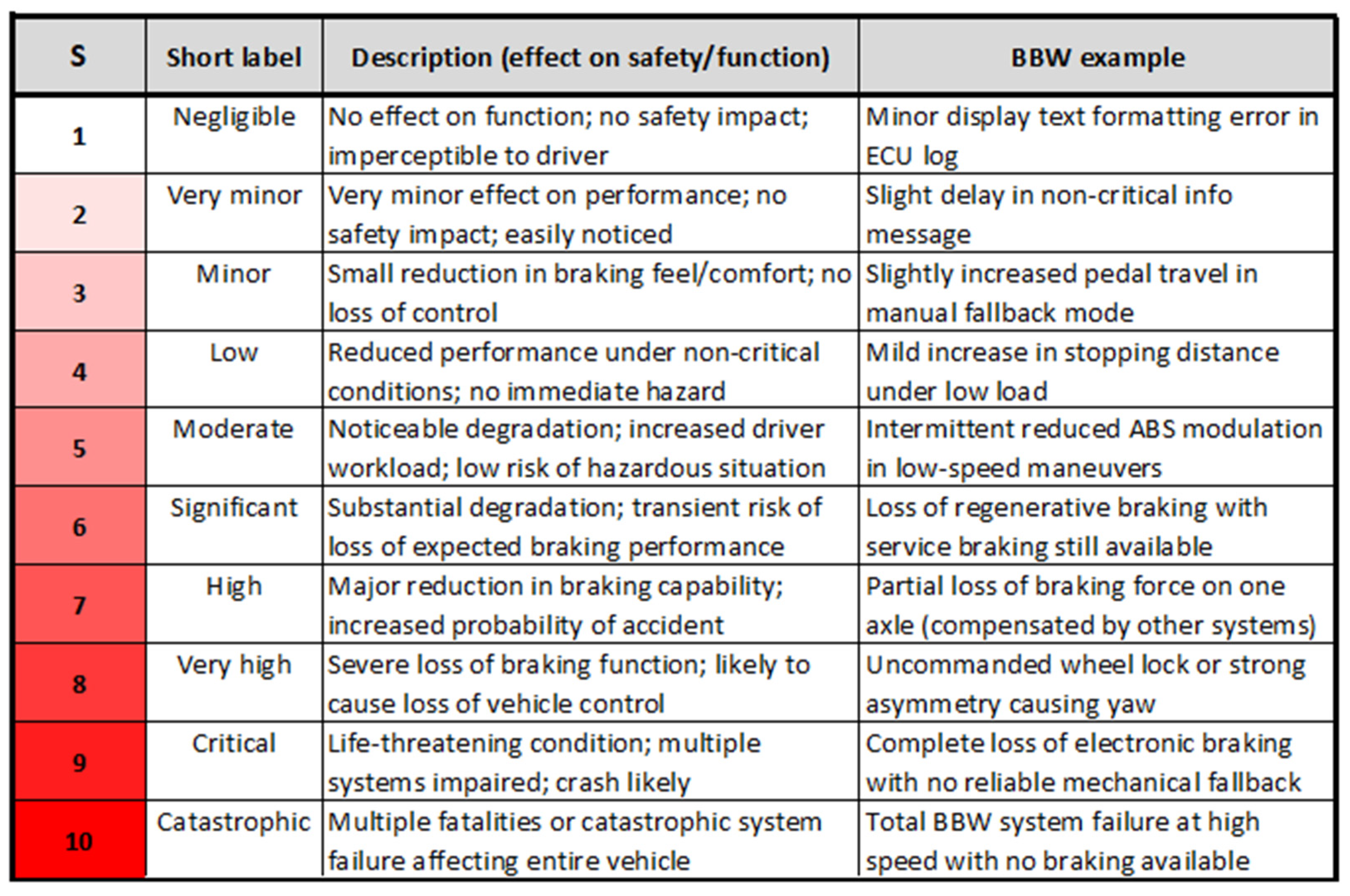
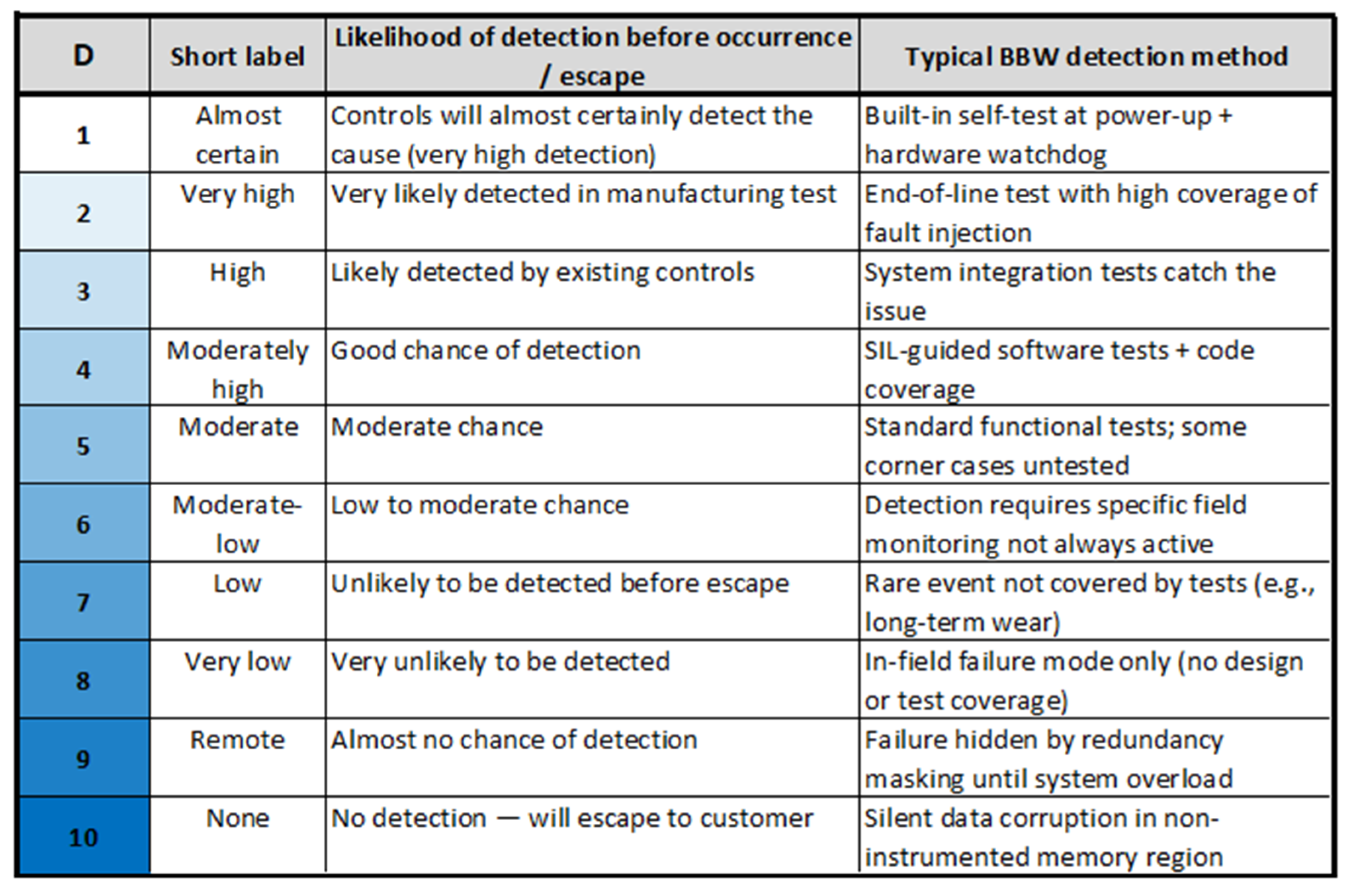
In this study, a comparative evaluation of FMEA applied to the BBW system is performed, incorporating both the traditional RPN method and the more recent AP approach. The analysis highlights the main methodological differences and overlaps, as well as their implications for safety assessment and subsequent decision-making. To support this comparison, customized evaluation tables were developed for the three FMEA parameters—severity (
Figure 3), occurrence (
Figure 4) and detection (
Figure 5).
The customized Severity (S), Occurrence (O), and Detection (D) tables were developed based on established automotive FMEA practices, particularly the AIAG–VDA methodology and adapted to the specific characteristics of brake-by-wire systems. The mapping between failure effects and S–O–D rankings is informed by domain knowledge of electromechanical actuation, braking safety constraints, and typical degradation mechanisms (thermal, mechanical, and control-related). To limit subjectivity, the assigned values are constrained by consistency with standard FMEA scales, literature-reported failure modes, and engineering judgment aligned with ISO 26262 safety considerations. Nevertheless, the absence of proprietary field data is acknowledged, and the ratings should be interpreted as representative rather than system specific.
The FMEA implementation team identified ten main functions of the BBW system, for which multiple associated failure modes were defined, summarized in
Figure 6. The BBW system encompasses several key functions: it converts the driver’s brake pedal input signal into electronic signals processed by the ECU, generates braking force through electro-hydraulic or electro-mechanical actuators, and provides realistic haptic response through pedal feedback. It also maintains stability through dynamic brake force distribution through EBD and by preventing wheel lock or excessive wheel spin through ABS/ESC. It is important to note that the system ensures reliability through redundancy and safety mechanisms, while the brake combination coordinates regenerative and mechanical braking to optimize both energy recovery and performance.
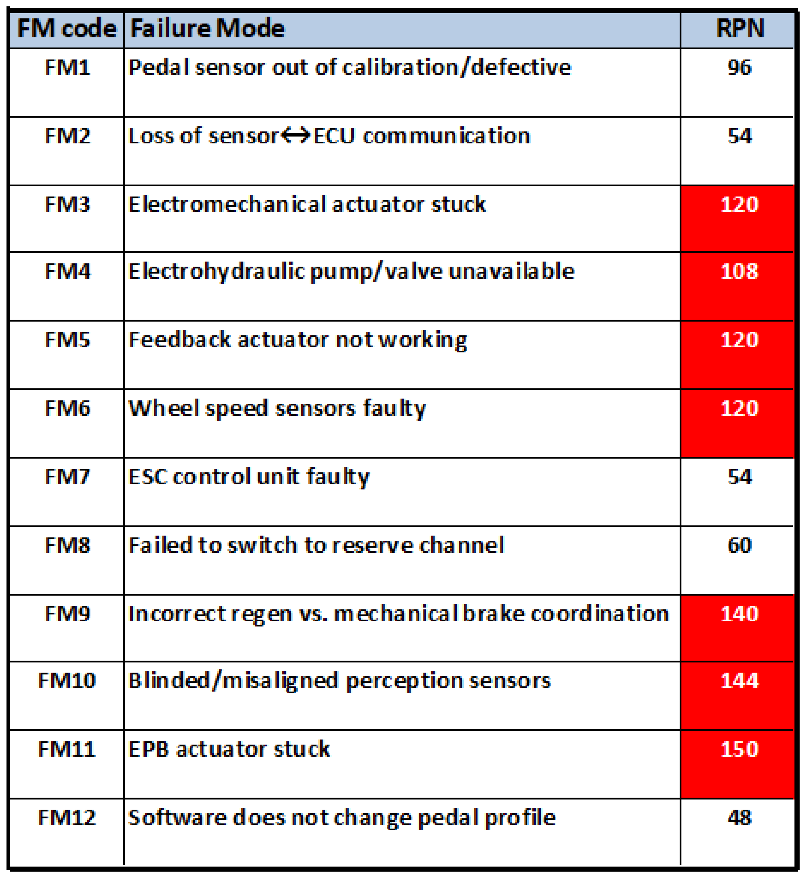
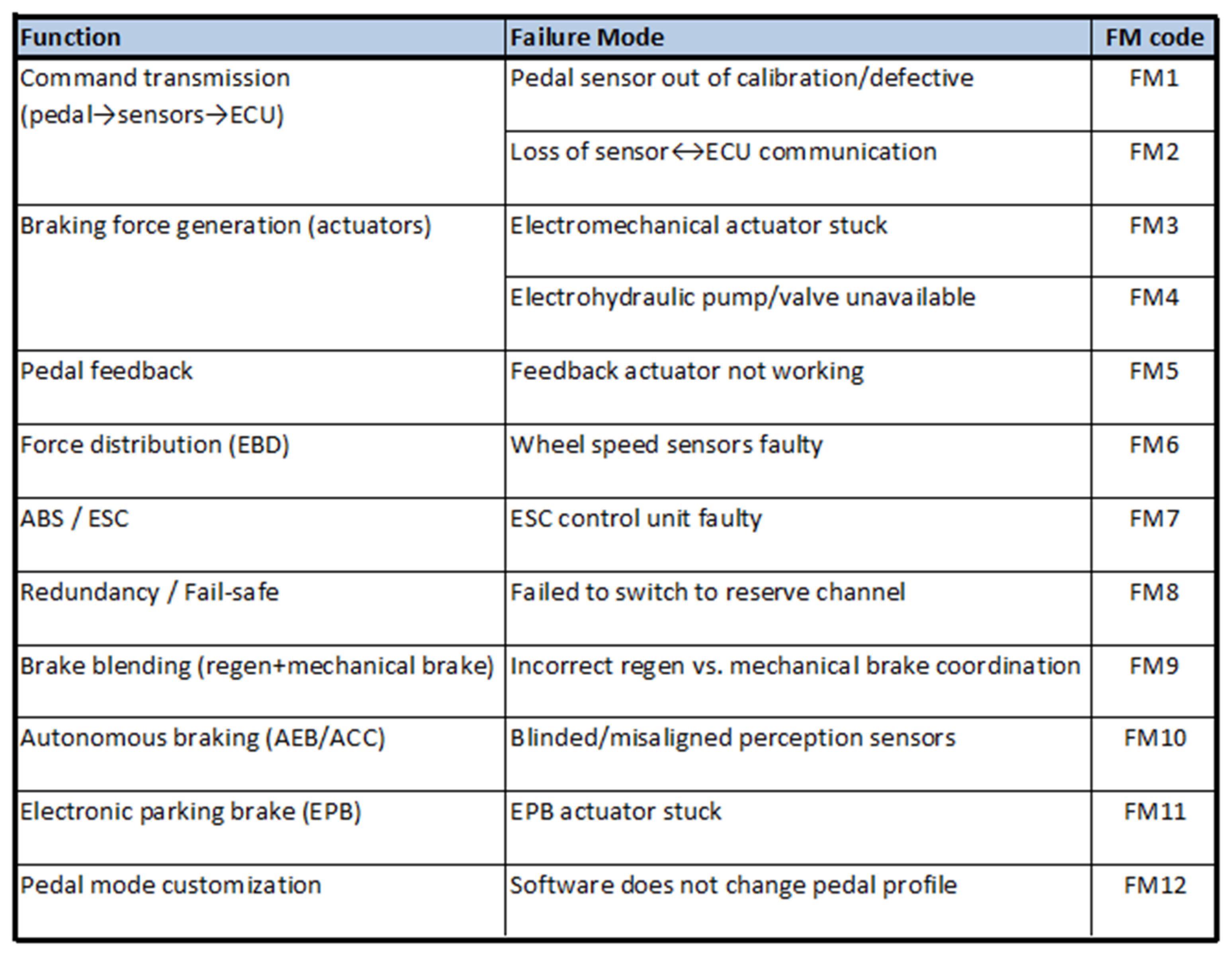
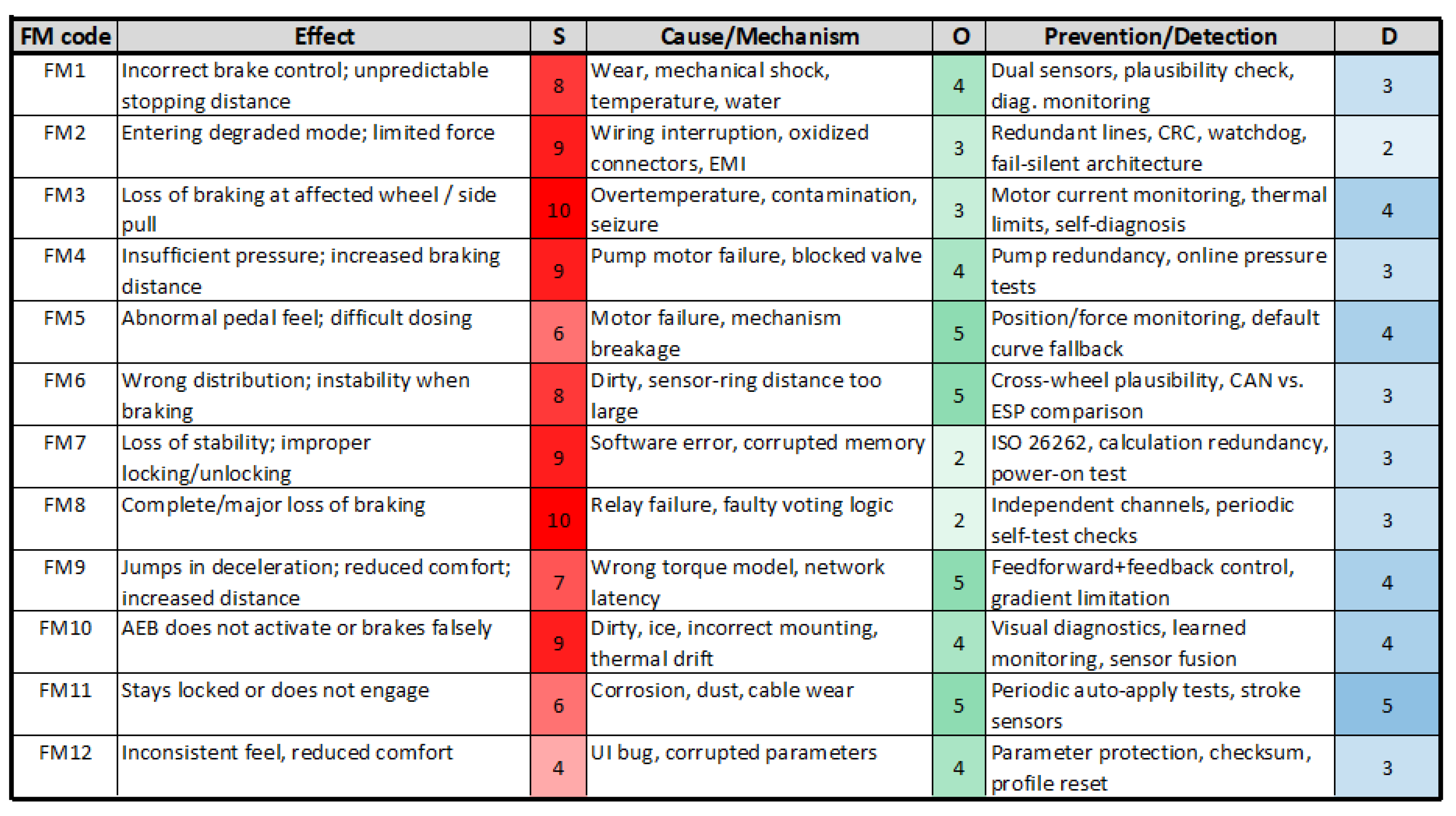
Autonomous braking (AEB/ACC) functions intervene automatically to prevent or mitigate collisions, and the electronic parking brake (EPB) secures the vehicle when stationary. Additionally, pedal mode customization adapts the pedal response to the selected driving mode, improving the overall driving experience. The implementation team’s brainstorming analysis generated 12 potential failure modes (FM1–FM12), as summarized in
Figure 7. Subsequently, each FM was assigned a severity rating based on the scale in
Figure 3, a cause was identified for each failure mode, allowing the assignment of an occurrence value in accordance with
Figure 4. The procedure was completed by assigning a detection rating, through the existing controls (Prevention/Detection) according to those predefined in
Figure 5. Effective implementation of FMEA, according to the AIAG-VDA FMEA methodology, requires a multidisciplinary and cross-functional team to ensure a structured and consistent risk assessment throughout the system life cycle [
1,
25].
For the BBW system under analysis, the FMEA team is typically comprised of system and functional safety engineers responsible for ISO 26262 compliance and element definition, brake and chassis engineers with detailed knowledge of BBW architecture and actuator technologies, and control and software engineers involved in ECU algorithms, diagnostics, and fault management strategies. In addition, electronics and hardware specialists in the area of sensor analysis, power electronics, and communication interfaces may be involved. Process-related failure causes may fall under the responsibility of production and quality engineers. Detection controls and verification measures can also be evaluated by test and validation engineers, according to the AIAG-VDA Action Priority concept [
26,
27]. The involvement of representatives from the reliability, cybersecurity and supplier fields further strengthens the means–end relationships and interface analyses, ensuring the traceability, consistency and robustness of the FMEA BBW in accordance with the AIAG-VDA guidelines. The present analysis was conducted without the full involvement of a multidisciplinary FMEA team, as typically recommended by the AIAG–VDA methodology. This limitation may introduce bias in the assignment of S–O–D values and reduce the ability to capture real-world variability. To mitigate this, the analysis relies on literature-based validation, standard FMEA practices, and engineering-informed assumptions (
Figure 7). Nevertheless, future work should include cross-functional collaboration involving design, manufacturing, and safety experts, as well as access to industrial datasets, to improve robustness and validation of the results. From this point onward, the FMEA analysis is conducted along two distinct methodological paths, corresponding, respectively, to the RPN evaluation and the AP assessment.
3.1. The Risk Priority Number (RPN) Analysis
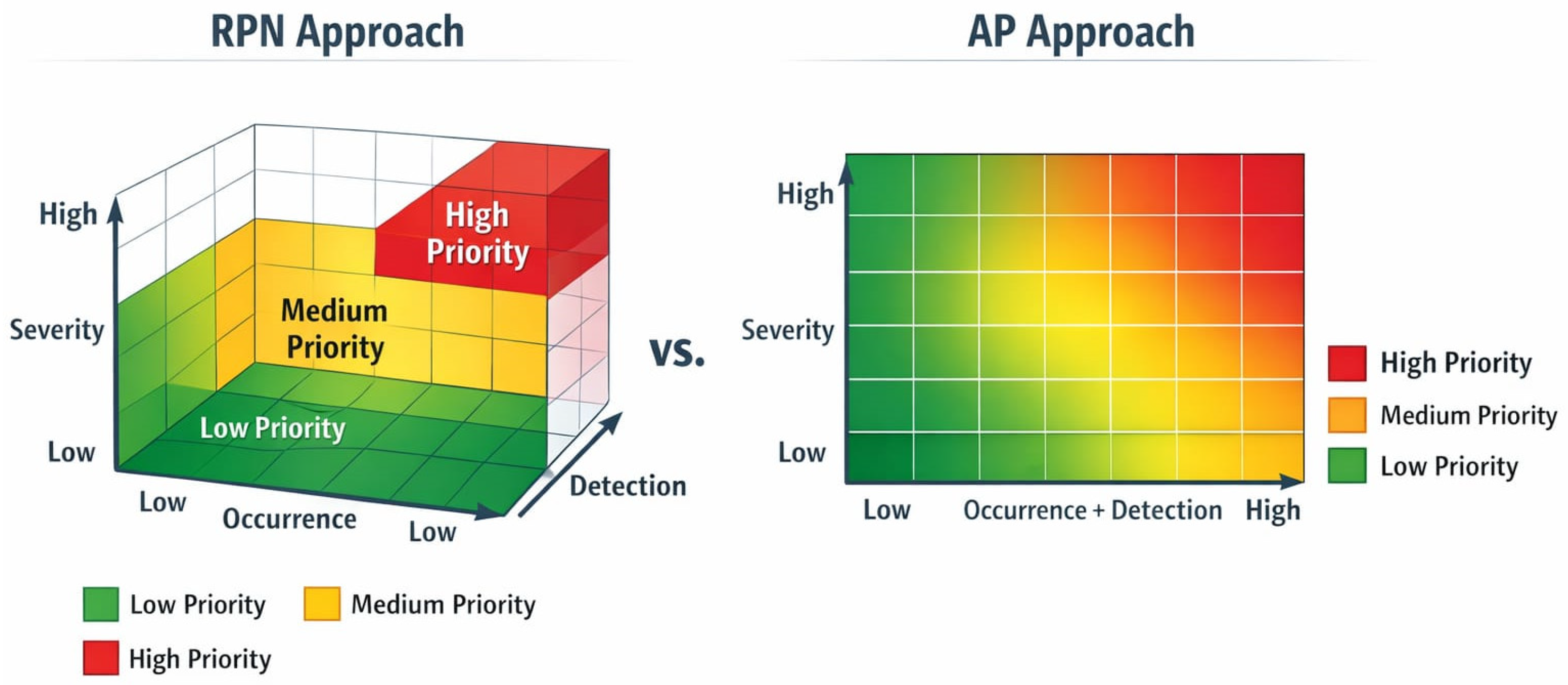
The traditional RPN approach involves multiplying the three FMEA parameters—severity, occurrence, and detection—to obtain a single RPN value, which can theoretically range from 1 to 1000. However, studies indicate that certain RPN values are more frequently observed in practice [
27,
28].
Although no universally accepted RPN threshold exists in the automotive industry, many OEMs and suppliers have historically adopted internal acceptance criteria. Typically, RPN values below 50 are considered acceptable, values between 50 and 100 are deemed tolerable with recommended corrective actions, and values above 100 are regarded as unacceptable, necessitating mandatory mitigation measures. In the case of the BBW analysis presented, the RPN values corresponding to the 12 identified failure modes are shown in
Figure 8. An acceptance threshold of 100 has been established, with all values exceeding this limit being flagged for further review and corrective action. The highest RPN values are observed for FM11, FM10, and FM9, respectively. Here is a brief description of the choice of values for the third parameters in the case of these potential failures. Although FM8 exhibits a high severity level, its overall RPN remains lower due to reduced occurrence and improved detection. The occurrence was estimated as O = 2, reflecting the low probability of such events due to control validation mechanisms and system safeguards implemented in brake-by-wire architectures.
Detection was assigned D = 3, as supervisory control algorithms and plausibility checks can identify abnormal commands, although some transient faults may not be immediately detectable. For FM9, the severity was evaluated as S = 7, since thermal overload degrades actuator performance and may reduce braking efficiency, affecting vehicle safety without causing immediate total failure. The occurrence was estimated as O = 5, considering repeated braking cycles, environmental conditions, and heat accumulation during operation. Detection was rated D = 4, as temperature monitoring and diagnostic functions enable identification of overheating conditions, although thermal degradation may develop progressively. For FM10, the severity was rated S = 9 because mechanical jamming can significantly impair brake application or release, directly affecting braking performance and vehicle controllability. The occurrence was estimated as O = 4, reflecting a moderate likelihood associated with wear, contamination, or mechanical component degradation over time. Detection was assigned D = 4, since mechanical faults may be partially detected through abnormal actuator behavior or current monitoring, but may not always be identified immediately.
The subsequent step in the FMEA involves identifying corrective measures for failure modes that exceed the acceptance threshold, accompanied by an action plan detailing the deadline, responsible individual or team, expected outcomes, and the anticipated reduction in RPN after implementation. In this comparative analysis, however, only the initial stage—identifying potential solutions—will be summarized. While RPN-based mitigation strategies often focus on reducing a single parameter, in practice combined improvements in occurrence and detection are frequently implemented. Accordingly, for FM3 (electromechanical actuator stuck), the application of anti-seize materials, enhanced dust and water protection, and extended end-of-line (EOL) testing directly target mechanical wear, contamination, and latent manufacturing defects, thereby reducing the occurrence (O) of actuator jamming. For FM4, liquid filtration and predictive maintenance, strategies that are intended to limit contamination- and aging-related failures, again primarily lowering the occurrence (O) of pressure generation loss. For FM5, a higher-efficiency lubrication system that will reduce friction and wear of moving parts, addressing progressive degradation mechanisms and consequently decreasing the occurrence (O) rating. For FM6, enhanced dirt protection and increased maintenance, intervals aim to reduce exposure to environmental contaminants, leading to a lower occurrence (O) of sensor malfunction. In the case of FM9 (incorrect regenerative versus mechanical brake coordination), improved synchronization with the vehicle network primarily addresses timing and communication-related inconsistencies, which are expected to reduce the occurrence (O) of coordination errors at system level. For FM10, sensor preheating and self-alignment verification routines are intended to mitigate environmental and installation-related effects, thus lowering the occurrence (O) of degraded sensor inputs. Finally, for FM11 (EPB actuator stuck), improved sealing using more durable materials limits moisture ingress and corrosion, directly targeting failure initiation mechanisms and reducing the occurrence (O) rating. To enhance the practical applicability of the FMEA results, corrective measures were proposed for the failure modes with the highest Action Priority. For each case, preventive or detection mechanisms were identified and their expected influence on Occurrence (O) and Detection (D) ratings was estimated. The updated ratings allow evaluation of the potential reduction in Risk Priority Number (RPN). We discussed the highest RPN’s (FM9, FM10 and FM11, respectively). For FM9, the risk of actuator thermal overload can be reduced by introducing enhanced thermal management strategies, including temperature monitoring, thermal protection algorithms, and improved heat dissipation design. These measures limit excessive temperature rise and enable early detection of overheating conditions. As a result, the likelihood of failure is reduced and overheating can be identified earlier, leading to a decrease in the occurrence rating from O = 5 to O = 3 and an improvement in detection from D = 4 to D = 2. The combined effect significantly lowers the Risk Priority Number from RPN = 140 (S = 7, O = 5, D = 4) to RPN = 42 (S = 7, O = 3, D = 2), indicating substantial risk reduction and improved system reliability. For FM10, to address mechanical jamming risks, the use of condition monitoring techniques, such as actuator current monitoring, position feedback validation, and preventive maintenance strategies, is proposed. These measures allow for the early identification of abnormal mechanical resistance and progressive component degradation. While the occurrence of mechanical wear may not be fully eliminated, improved monitoring enhances fault detectability, reducing the detection rating from D = 4 to D = 2, and preventive maintenance slightly reduces occurrence from O = 4 to O = 3. These improvements reduce the Risk Priority Number from RPN = 144 (S = 9, O = 4, D = 4) to RPN = 54 (S = 9, O = 3, D = 2). To mitigate performance degradation or response delay (for FM11), the implementation of performance monitoring algorithms, adaptive control strategies, and periodic calibration procedures is proposed. These measures enable continuous evaluation of actuator response time and braking performance, allowing early detection of gradual system degradation. In addition, preventive maintenance and component health monitoring reduce the likelihood of progressive performance loss. As a result, the occurrence rating is reduced from O = 5 to O = 3, while improved monitoring enhances detectability, reducing the detection rating from D = 5 to D = 3. Consequently, the Risk Priority Number decreases from RPN = 150 (S = 6, O = 5, D = 5) to RPN = 54 (S = 6, O = 3, D = 3), indicating a significant reduction in risk and improved system performance reliability.
3.2. The Action Priority (AP) Methodology and Analysis
In recent years, the traditional RPN approach in FMEA has been increasingly replaced by the AP methodology, as recommended in the AIAG-VDA FMEA Manual [
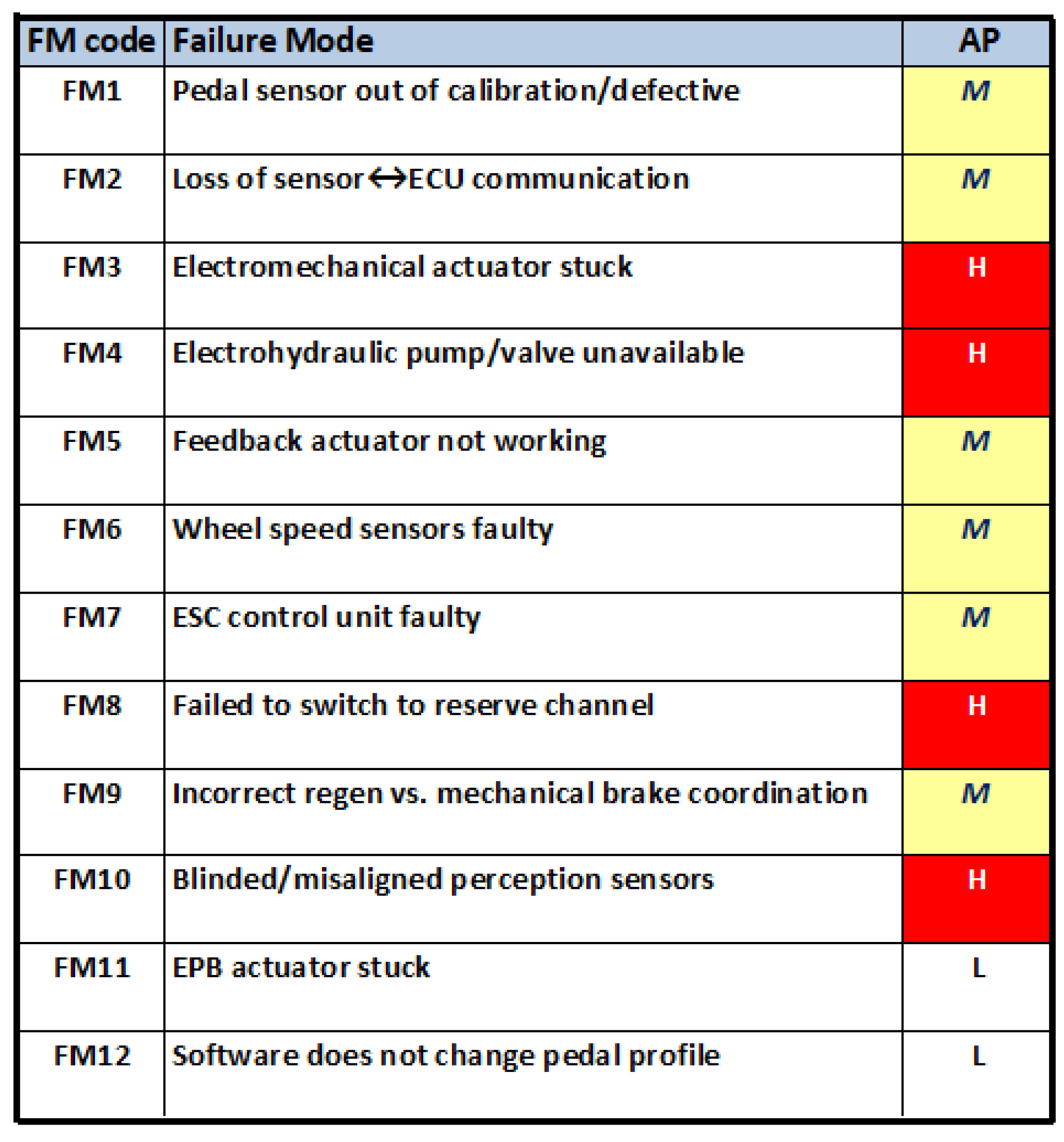
26]. This is also the result of the unification of the FMEA approach for North American and European automotive manufacturers. Unlike the previously presented RPN, AP provides a more structured and actionable risk assessment by classifying failure modes into High, Medium, or Low priority levels based on the combination of these parameters. This approach mitigates the limitations of RPN, such as non-uniform distribution, ambiguity in threshold selection, and lack of direct guidance for corrective actions. By using AP, teams can more effectively identify and prioritize critical failure modes, define appropriate mitigation measures, and ensure that safety-critical and high-risk elements receive timely attention, thereby increasing the reliability and overall safety of systems, such as Brake-by-Wire architectures. The concept of AP starts with a prioritization of defects based on severity, then considers occurrence, and the detection or prevention mode represents the final step in risk assessment. Analogous to the RPN analysis presented in
Figure 8,
Figure 9 illustrates the AP evaluation for the same set of 12 identified failure modes, in accordance with the AP Table for DFMEA (Design FMEA) and PFMEA (Process FMEA) in [
26].
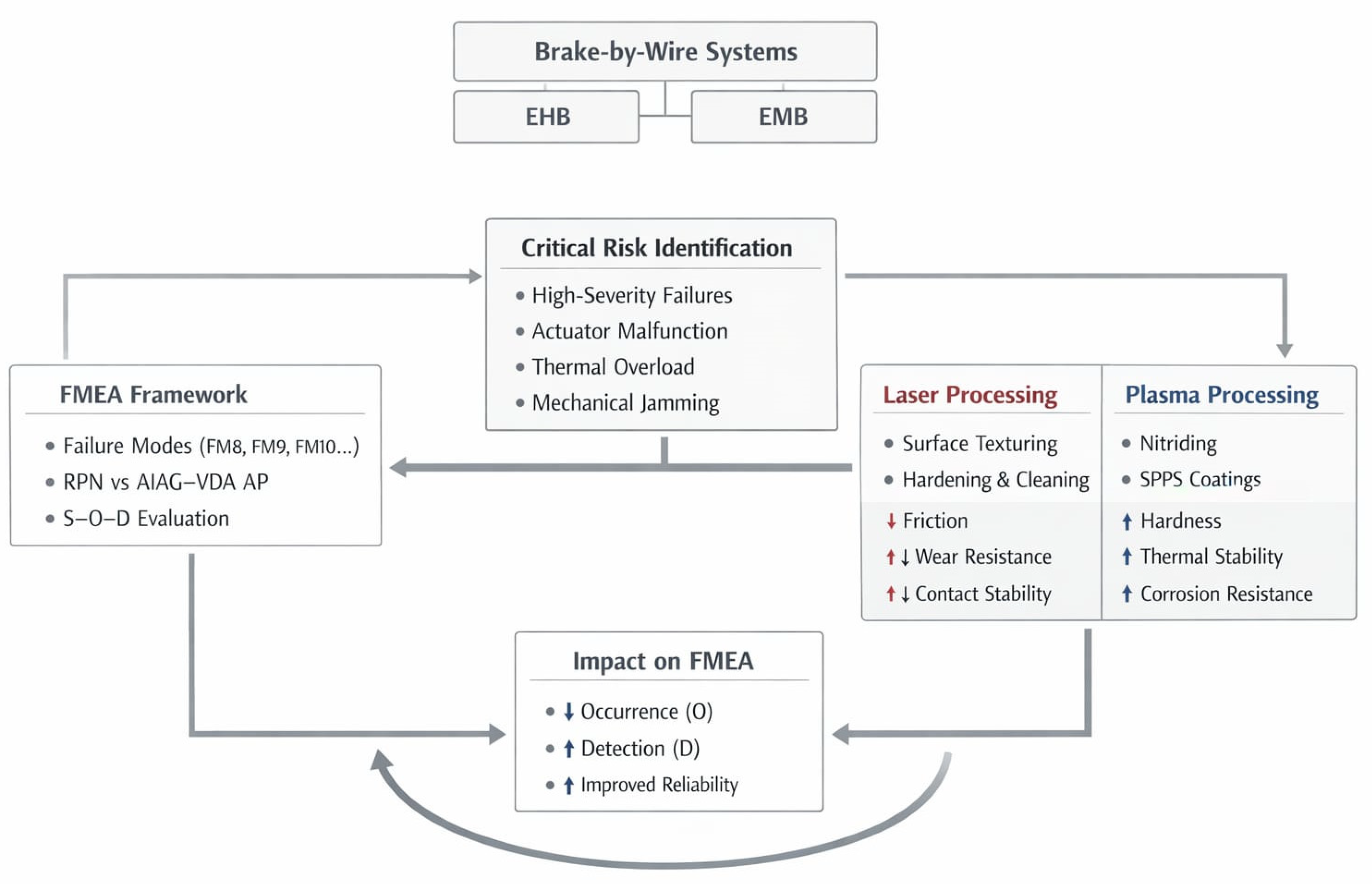
Regarding high AP, we will give a brief description of FM3 and FM4. FM3 was assigned a High Action Priority (H) due to its critical impact on vehicle safety. The severity was rated S = 10, as complete actuator failure results in loss of braking torque, which may lead to loss of vehicle control and hazardous driving conditions. The occurrence was estimated as O = 3, reflecting the relatively low but non-negligible probability of actuator failure due to electrical or mechanical faults. Detection was evaluated as D = 4, since although electrical faults can be identified through current monitoring and diagnostic functions, sudden mechanical failures may not be immediately detectable. The combination of very high severity and limited detection capability justifies the High Action Priority classification. FM4 was also classified with High Action Priority (H) because control unit malfunction may generate incorrect or missing brake commands, directly affecting braking performance and system safety. The severity was rated S = 9, as erroneous control signals can lead to unintended braking behavior or insufficient braking force. The occurrence was estimated as O = 4, considering potential software errors, electronic component degradation, or signal processing faults. Detection was assigned D = 3, as controller self-diagnostics and monitoring functions enable fault detection, although certain failure modes may propagate before being identified. The high safety impact combined with a non-negligible occurrence level supports the High Action Priority assignment. For the identified failure modes with high action priority (FM3, FM4, FM8 and FM10), immediate corrective actions must be implemented to ensure system reliability and safety. For FM3 (electromechanical actuator stuck), it is proposed to introduce regular actuator diagnostics and preventive maintenance routines, along with the integration of redundant drive paths. The integration of redundant actuation paths or mechanically decoupled fallback mechanisms enables continued braking capability in case of primary actuator failure (reducing S). In addition, controlled derating strategies and preventive maintenance based on usage and load history can reduce the probability of occurrence and limit the progression of latent faults (reducing detection). FM4 requires the installation of backup hydraulic circuits and real-time pump status monitoring, real-time monitoring of pump speed, pressure build-up, valve position, and electrical supply enables early fault detection and controlled transition to degrade operating modes. These measures increase both detection capability and system resilience under fault conditions. Architectural redundancy and component derating strategies further reduce occurrence (O) by lowering the probability of simultaneous or stress-induced failures. FM8 can be mitigated by software updates that enable automatic failover logic and continuous channel status verification. The deployment of independent and continuously supervised failover logic, including watchdogs and periodic self-tests of reserve channels, significantly improves detection (D) by ensuring timely identification of switchover faults. Finally, FM10 requires periodic sensor calibration, environmental protection enclosures and fault-tolerant sensor fusion algorithms. Fault-tolerant sensor fusion and plausibility checks against vehicle dynamics signals improve detection (D) by identifying inconsistent or degraded sensor inputs. Mechanical protection measures and robust sensor mounting reduce occurrence (O) by limiting exposure to environmental and alignment-related faults. All these measures aim to reduce the risk of critical failures and maintain high functional safety performance. The proposed corrective measures demonstrate that high-priority risks can be significantly reduced through redundancy, enhanced diagnostics, and fault-tolerant control strategies, confirming the practical usefulness of the Action Priority framework for guiding safety-oriented design improvements. The action plan was focused on FM3 and FM 4. FM3 was initially classified with High Action Priority due to its maximum severity (S = 10), reflecting the critical safety impact of complete loss of braking torque. To reduce this risk, actuator redundancy, continuous current and position monitoring, and fault-tolerant control strategies (e.g., limp-home functionality) are proposed. These measures reduce the occurrence from O = 3 to O = 2 and improve detection from D = 4 to D = 2, while severity remains unchanged. Consequently, the Risk Priority Number decreases from RPN = 120 to RPN = 40, and the resulting Action Priority is reduced from High to Medium, indicating improved system safety through enhanced reliability and diagnostic coverage. On the other hand, FM4 was also assigned an initial High Action Priority because incorrect or missing control signals may significantly affect braking performance (S = 9). The proposed mitigation measures include redundant control architecture, watchdog monitoring, and enhanced software validation and diagnostic mechanisms. These actions reduce the occurrence from O = 4 to O = 2 and improve detection from D = 3 to D = 2, with severity remaining unchanged. As a result, the Risk Priority Number decreases from RPN = 108 to RPN = 36, leading to a reduction in Action Priority from High to Medium, reflecting improved fault detection and system robustness. This effect is particularly evident for the most critical failure modes identified in this study, such as FM8 (actuator malfunction), FM9 (thermal overload), and FM10 (mechanical jamming), where comparable RPN values are associated with different Action Priority levels, highlighting the stronger sensitivity of the AIAG–VDA methodology to high-severity risks. These results highlight the limitations of RPN-based prioritization and the improved consistency of the AIAG–VDA Action Priority approach, providing a robust foundation for the discussion of system-level implications and the role of advanced manufacturing strategies in mitigating critical failure modes.
5. Conclusions
This study presented a comparative Failure Modes and Effects Analysis (FMEA) of electro-hydraulic (EHB) and electro-mechanical (EMB) brake-by-wire architectures, integrating both the traditional Risk Priority Number (RPN) approach and the AIAG–VDA Action Priority (AP) methodology within a unified analytical framework. By applying both methods to the same set of representative failure modes, the work provides a consistent basis for evaluating differences in risk prioritization and decision-making strategies. The results demonstrate that although RPN and AP may converge in clearly critical scenarios, they exhibit systematic divergences in cases involving high-severity failure modes. In particular, the multiplicative nature of RPN may underestimate critical risks when severity is not dominant in the numerical combination, whereas the AP methodology ensures that safety-critical failure modes are consistently prioritized. This highlights the limitations of traditional RPN-based evaluation and supports the adoption of structured, rule-based prioritization frameworks in safety-critical automotive systems. From an architectural perspective, the comparison between EHB and EMB systems reveals distinct reliability characteristics. EHB architectures benefit from inherent hydraulic redundancy, contributing to improved fault tolerance, while EMB systems offer superior responsiveness and integration potential but require advanced electrical and electronic redundancy strategies. In addition, recent advances in integrated x-by-wire vehicle control architectures, including game-theoretic and multi-agent approaches, further highlight the increasing system-level complexity and the need for structured, transparent reliability assessment methodologies such as those proposed in this work. These differences directly influence failure mode criticality and must be carefully considered in system design and risk assessment. A key contribution of this work is the integration of reliability analysis with advanced manufacturing strategies. By establishing a link between failure mechanisms and material-level mitigation approaches, this study demonstrates how laser and plasma-based surface engineering can reduce failure occurrence and enhance system robustness. This perspective extends the role of FMEA beyond risk identification, positioning it as a tool for guiding design and manufacturing decisions. The study also acknowledges several limitations. The analysis is based on representative failure modes and engineering-informed S–O–D assignments, without access to proprietary field data or a fully multidisciplinary evaluation team. In addition, uncertainty in parameter estimation is not explicitly modeled. These aspects may influence the quantitative results but do not affect the overall methodological conclusions. Also, in the context of rapidly evolving x-by-wire vehicle architectures and increasingly integrated control strategies, the present work complements recent advances in control-oriented approaches by demonstrating rigorous, structured reliability analysis remains essential for ensuring the safe and robust deployment of next-generation electronically controlled braking systems. Thus, future work will focus on extending the proposed framework through experimental validation, integration of industrial datasets, and the inclusion of probabilistic or data-driven FMEA approaches. The application of the methodology to other x-by-wire systems, such as steer-by-wire architectures, also represents a promising direction for generalization. Ultimately, this work demonstrates that reliable system design in next-generation automotive technologies requires a holistic approach, where risk assessment methodologies, system architecture, and advanced manufacturing strategies are considered in a unified framework. By bridging these domains, the proposed approach contributes to the development of safer, more robust, and more intelligent brake-by-wire systems, supporting the ongoing transition toward electrified, autonomous, and highly integrated vehicle platforms. Beyond the specific case of brake-by-wire systems, the proposed framework highlights a broader paradigm in which reliability assessment, system architecture, and advanced manufacturing must be co-designed to meet the stringent safety and performance requirements of next-generation cyber–physical systems.