1. Introduction
Reverse engineering is a distinct engineering activity that is gaining growing significance today, to the point that it is developing into its own sector within the technical industry. This approach is crucial for reproducing damaged components and for improving and refining existing designs [
1]. In contrast to conventional engineering design workflows, reverse engineering starts not in a digital setting but with an already existing physical part. In a traditional design workflow, the initial step involves creating a digital representation of the component using CAD (Computer-Aided Design) software. After this model has been finalized, the component proceeds to manufacturing [
2]. In reverse engineering, the process begins with digitizing the existing part, then continues with its modification and optimization in a CAD environment and concludes with carrying out the manufacturing process [
3].
A key technology in reverse engineering is 3D scanning, which is employed in a wide range of industrial fields. This technique enables objects to be digitized without any physical contact, as the scanner captures hundreds of data points from the surface of the component being inspected. Using this collected data, a highly accurate digital model of the object can be recreated within a virtual environment [
4,
5]. Beyond dimensional control, technology is also crucial for advancing and optimizing existing components, particularly when the original design was produced without the use of a CAD system. However, despite the clear benefits of 3D scanning, the procedure is associated with high costs and substantial software demands [
6].
Alongside 3D scanning, 3D printing is also becoming more established in industrial manufacturing. While it was originally used primarily for producing prototypes, it is now increasingly employed for series production [
7,
8,
9]. 3D printing is an additive manufacturing process that creates components layer by layer, thereby reducing material waste [
10,
11]. Ongoing advances in printing technologies enable the use of an ever-broader spectrum of materials, including composite materials with exceptional properties. The arbitrary orientation of the reinforcing components makes it possible to tailor structures to loading conditions [
12,
13]. Composites are made up of two parts: a reinforcement and a matrix, whose combination produces exceptional mechanical properties [
14]. An advantage of additive manufacturing is the ability to position reinforcing materials in line with the applied loads, making it possible to produce components with higher strength [
15,
16].
The literature contains numerous scientific studies that focus on the design of various small objects and their fabrication through 3D printing technology [
17,
18]. Numerous studies indicate that 3D printing technologies exhibit excellent mechanical performance, making them well-suited for applications in both the automotive and aerospace sectors [
19,
20].
A previous study examined whether it is possible to correctly reconstruct the geometry of worn, non-standard gears using reverse engineering methods and conventional techniques and measured instruments commonly available in most design offices and laboratory workshops [
21].
Another study uses a combination of 3D scanning and 3D printing to produce various prototypes [
22]. An additional study indicates that 3D printing technology can also be applied to substitute components that were originally produced by injection molding but it lacks comprehensive technical documentation [
23].
Recent studies have also explored advanced material development and process optimization in additive manufacturing, including nanocomposite-based approaches and AI-assisted process enhancement [
24,
25].
Previous work in reverse engineering and additive manufacturing has predominantly focused on replacing damaged parts from narrow, technology-specific viewpoints. Certain studies emphasize the material science of fracture behavior, while others concentrate on 3D scanning accuracy, mesh processing methods, or the performance of additive manufacturing technologies. While these efforts yield important knowledge about distinct phases of the overall workflow, they are usually considered in isolation, without an integrated framework that links analysis, design modification, and production.
Consequently, only a few studies present a full, traceable engineering workflow that starts with the examination of a failed component and continues through digitalization, CAD-based geometric adaptation, and final fabrication. The majority of current research focuses on just one technological stage and does not explain how insights from earlier phases affect later design or manufacturing choices. In particular, there is still relatively little work that directly uses fracture surface analyses to guide changes in geometry and reinforcement strategies, especially when dealing with undocumented legacy components.
The present work tackles this gap by delivering a practical, yet scientifically robust, case study that illustrates an integrated reverse-engineering methodology for reproducing a damaged component lacking documentation. The component under study is a structural mounting element employed in an automotive lighting assembly. In service, it experiences a combination of loading conditions, including vibration, concentrated stresses at the attachment points, and thermal influences. The proposed process merges microscopic fracture surface examination, targeted refinement of 3D scan data, CAD-based adaptation of functional geometry, and continuous fiber-reinforced additive manufacturing. By explicitly connecting the outcomes of fracture analysis with geometric redesign and reinforcement choices, this study offers a coherent, transparent approach to the cost-efficient and structurally reliable replacement of low-volume, function-critical components.
The objective of this study is to develop an integrated workflow for reconstructing a damaged polymer component in the absence of original design data. The specific objectives are as follows:
To analyse the fracture surface of the failed component;
To reconstruct the geometry using 3D scanning and CAD modelling;
To design a fibre-reinforced replacement using fracture-informed engineering judgement;
To manufacture the component using continuous fibre-reinforced additive manufacturing;
To evaluate the functional performance of the reconstructed part.
2. Materials and Methods
The aim of the study was to reconstruct and manufacture a damaged plastic part, starting with a thorough assessment of its fractured surfaces. After this in-depth analysis, the component was digitized with a 3D laser scanner, and the resulting triangular mesh was subsequently optimized geometrically. Once the digital surface model had been created, scanning-related geometric inaccuracies were corrected, and the opening required for cable routing was designed in a CAD environment.
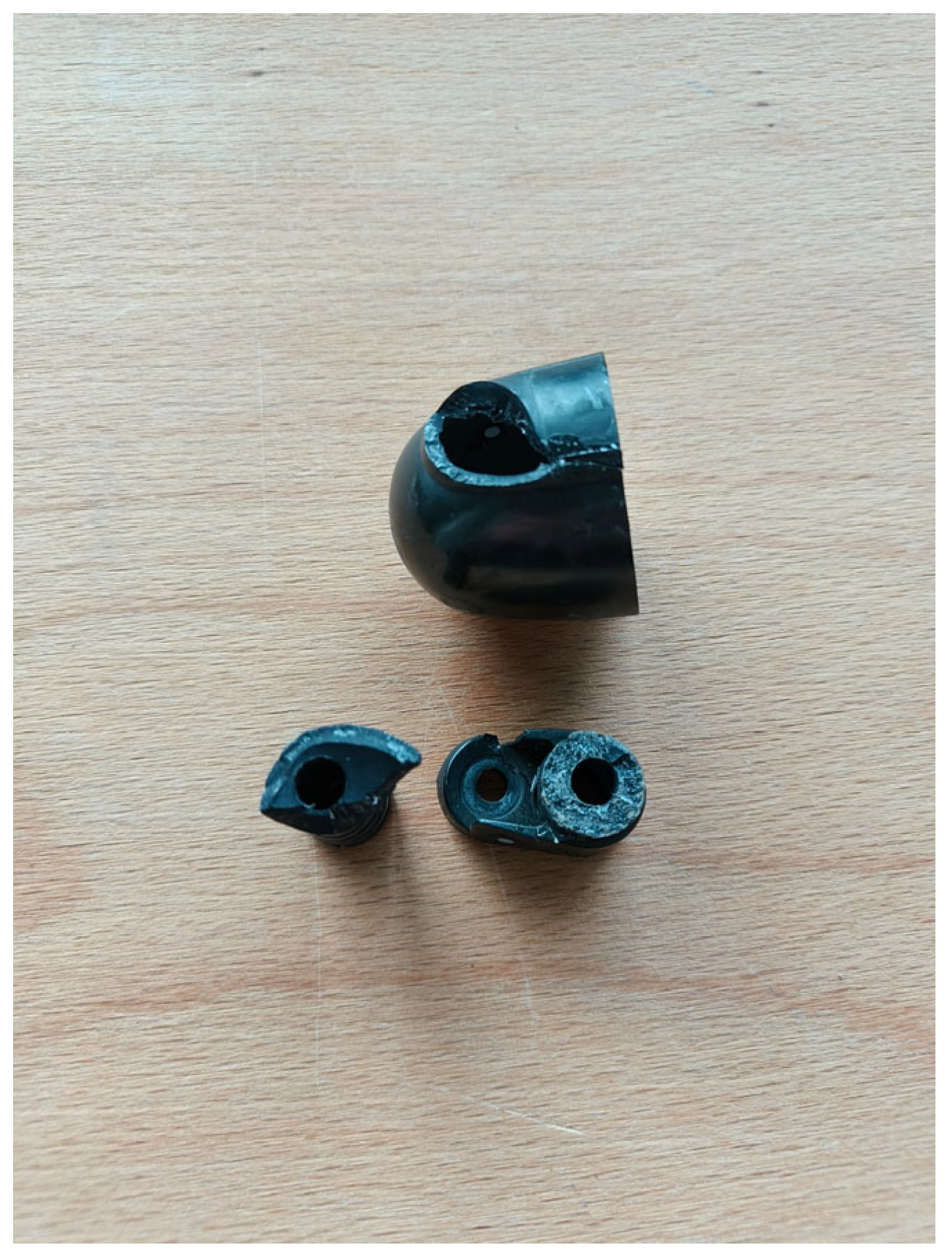
Figure 1 shows the broken original piece.
The part examined was a polymer lampshade manufactured by injection moulding. The specific polymer of the original part could not be clearly determined, as neither material certificates nor manufacturer information were available for the component. Considering its visual characteristics, the production process (injection moulding), and the typical field of use, the material is assumed to be a standard thermoplastic, for example, ABS, PP, or a comparable engineering polymer.
Due to the lack of access to advanced material identification techniques (e.g., DSC or FTIR), no further material characterization was performed. Consequently, the fracture analysis carried out in this study is based on qualitative interpretation of surface features rather than material-specific quantitative evaluation. The fracture behaviour of polymer components can range from mainly brittle to mainly ductile, and is influenced by factors such as molecular structure, operating temperature, loading rate, and manufacturing conditions.
Brittle fracture surfaces are typically smooth and show minimal plastic deformation, with clear directional markings that reveal the route of crack growth. By contrast, ductile fracture involves localized plastic deformation and, on the microscopic level, is characterized by fibril formation, shear bands, and a generally rougher surface texture.
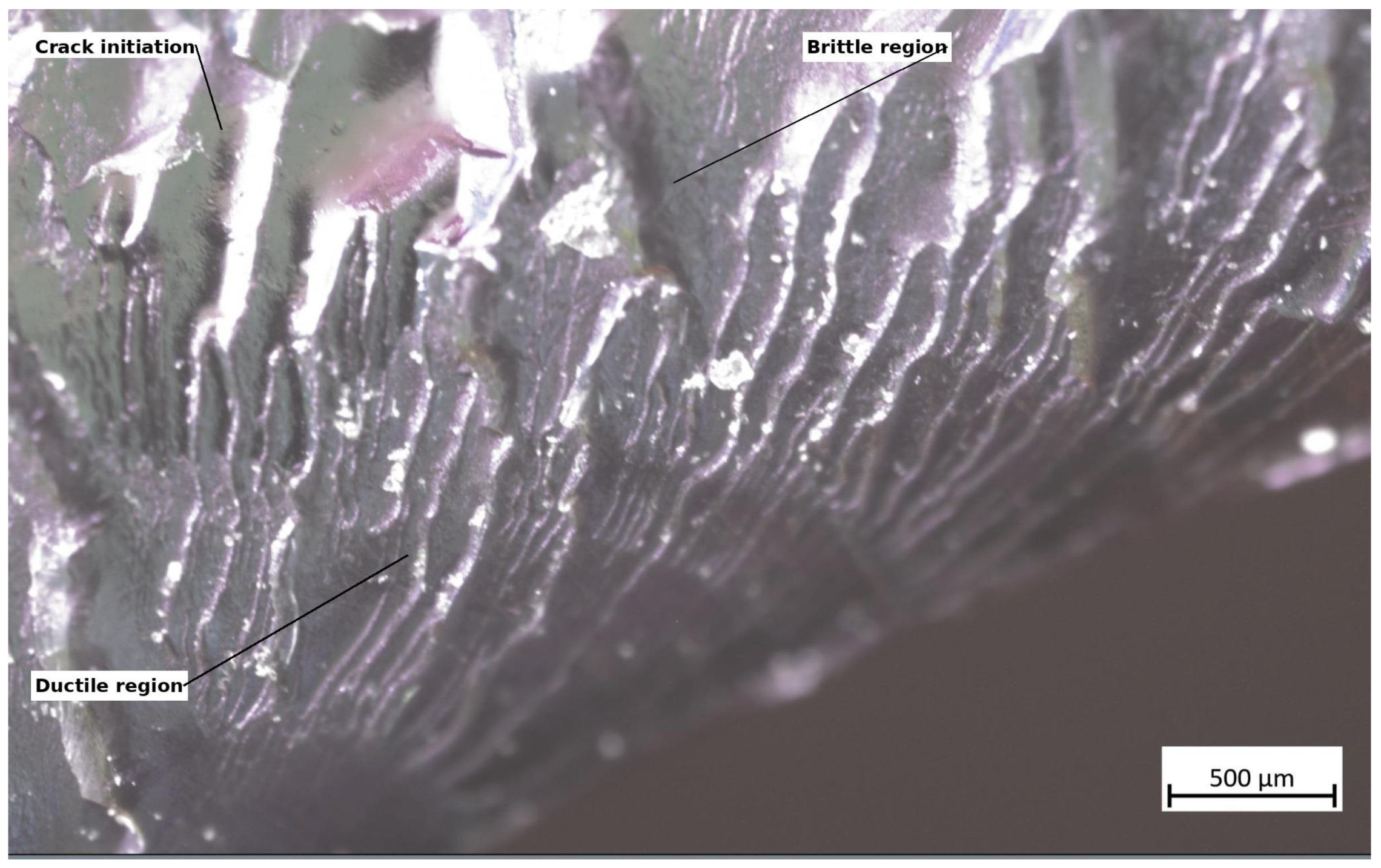
Microscopic inspection of the fracture surface revealed characteristics consistent with both brittle and ductile failure modes. The resulting fracture-surface assessment was then employed qualitatively to pinpoint key areas linked to crack initiation and subsequent growth. These findings were later incorporated into the CAD-driven redesign process to inform geometric changes and reinforcement measures. SEM examination was beyond the scope of this work, and no other high-resolution methods were available. Consequently, the fracture assessment is restricted to qualitative observations made with optical microscopy. A representative micrograph of this fracture surface is presented in
Figure 2.
Closer inspection of the fracture surface showed that the fracture morphology varied across the sample. Near the apparent crack initiation site, relatively smooth, featureless areas were present, indicative of locally brittle behaviour. In contrast, rougher zones exhibiting noticeable fibrillation and signs of plastic deformation appeared farther along the crack path, consistent with more ductile fracture mechanisms. The coexistence of these regions points to a mixed-mode failure, in which crack initiation took place under locally brittle conditions, followed by crack growth that absorbed more energy.
Before initiating the scanning procedure, it was crucial to carry out all required preparatory operations, since without these, the measuring system would not be capable of digitizing the inspected component with adequate precision and reliability. A key part of the preparation involved placing reference markers on the surface of the lampshade. These markers made it possible to continuously monitor the scanner’s position in space and to accurately align the recorded measurement data. With a suitable layout of the markers, a high-resolution, continuous point cloud could be generated, serving as the foundation for subsequent data processing and geometric analysis.
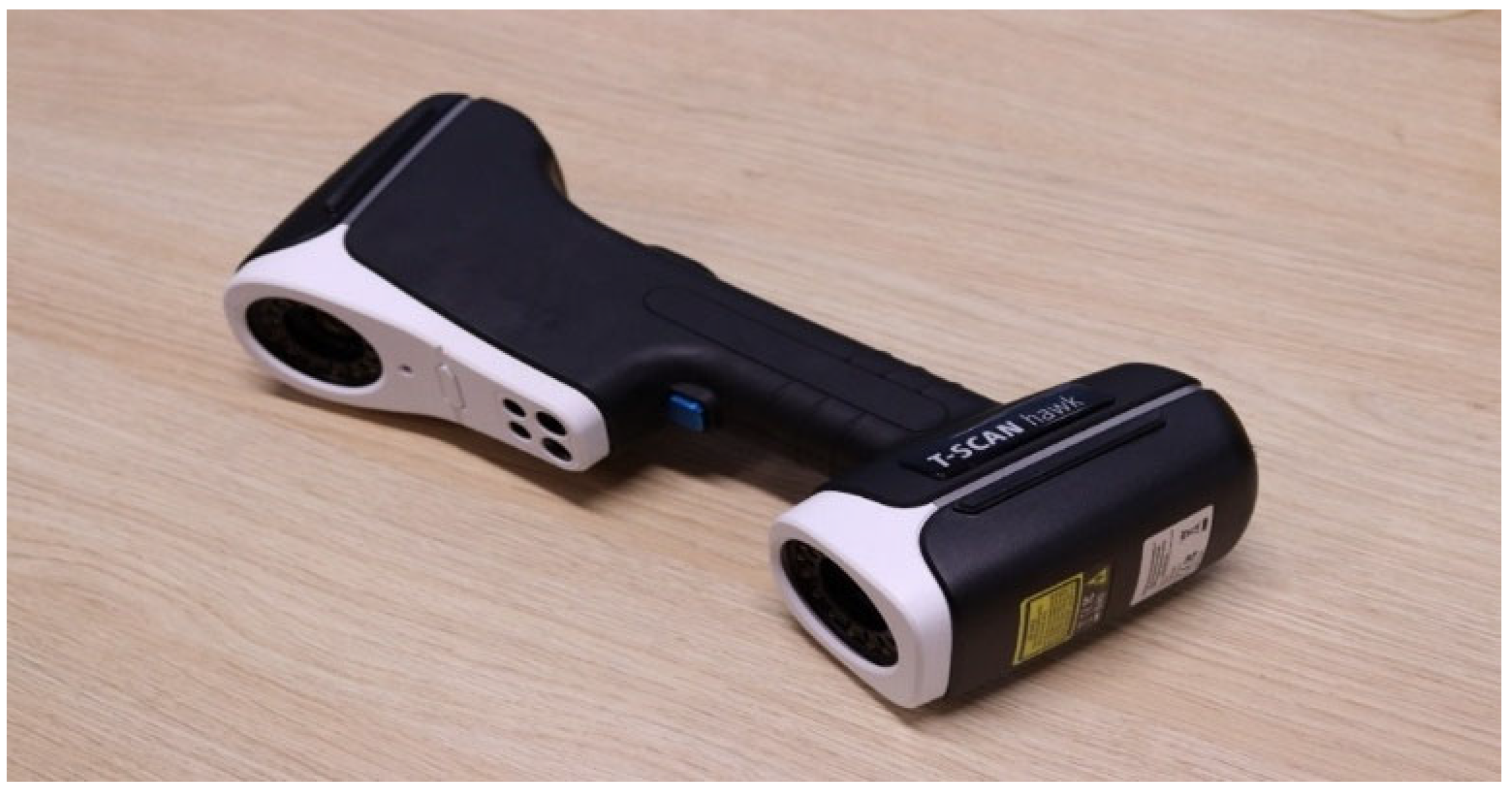
As shown in
Figure 3 for the digitization process, a Zeiss T-Scan Hawk 2 high-precision handheld laser scanner (Braunschweig, Germany) was employed, a system developed for industrial metrology and post-production quality control. The scanner provides high measurement accuracy, with a specified volumetric uncertainty of 0.02 mm + 0.015 mm/m. This precision allows for detailed, distortion-free three-dimensional acquisition of components with complex shapes, including larger-scale parts.
Scanning was carried out under typical indoor laboratory conditions; however, environmental parameters such as temperature and illumination were not systematically monitored, which has now been explicitly acknowledged as a limitation. The acquisition was conducted using the standard high-resolution settings recommended by the manufacturer, configured to capture fine geometric features of intricate surfaces. The point spacing was set to achieve dense coverage of the scanned surfaces, producing a high-resolution point cloud appropriate for reverse engineering tasks.
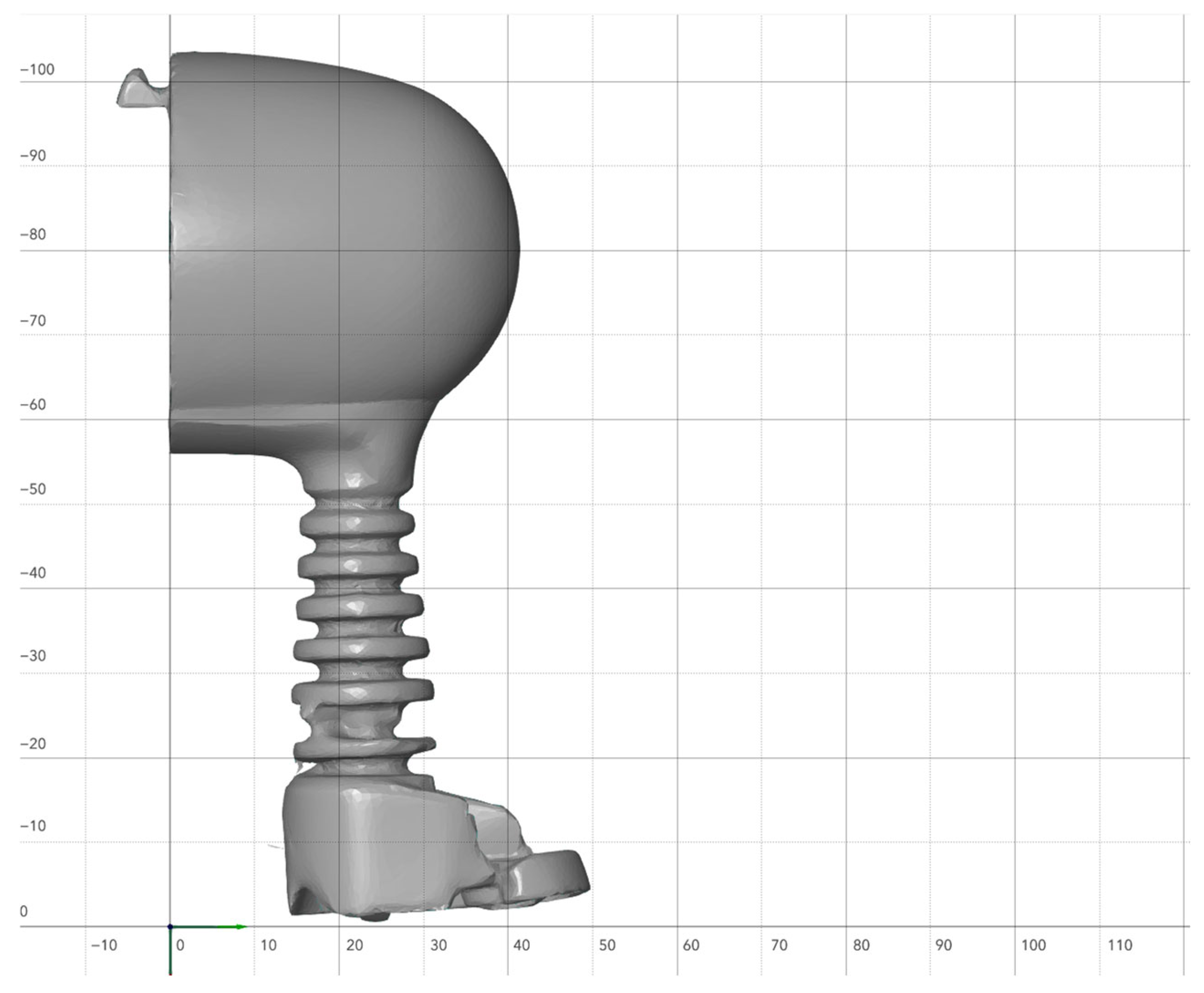
Regardless of how precise the scanner that we use to digitize a damaged component is, achieving a completely error-free scan is almost impossible. This is particularly true for the complex-shaped part I analyzed. Small inaccuracies are inevitable because the laser scanner cannot perfectly access every surface, which can introduce slight deviations. The scan output is a mesh that represents the 3D surface with interconnected triangles, as illustrated in
Figure 4.
The mesh inevitably contains slight imperfections from the scanning process, as well as unnecessary features (“debris”) that may appear in the dataset. To address these problems, Zeiss developed the GOM software (Version 2022), which is also embedded in the scanner. Using this tool, various post-processing operations can be performed on the mesh, such as correcting minor defects and removing irrelevant components. Mesh processing was carried out in GOM and involved removing scanning artefacts, discarding nonessential surface features, filling holes in areas with missing data, applying local smoothing, and aligning the model within a specified coordinate system. While these procedures may appear trivial, they are essential and significantly simplify all downstream work, particularly when the part is subsequently handled in CAD software.
Although the T-Scan laser scanner enables high-resolution digitization and the GOM software can be used to further refine the part’s geometric model, additional adjustments were still required in the final processing stage. This applies in particular to the longitudinal bore shown in
Figure 4, which will later accommodate an electrical cable. Owing to the inherent limitations of laser scanning, such deep features that are partially shielded from above cannot be captured with sufficient precision, so the final shape of this hole was modelled directly in CAD software.
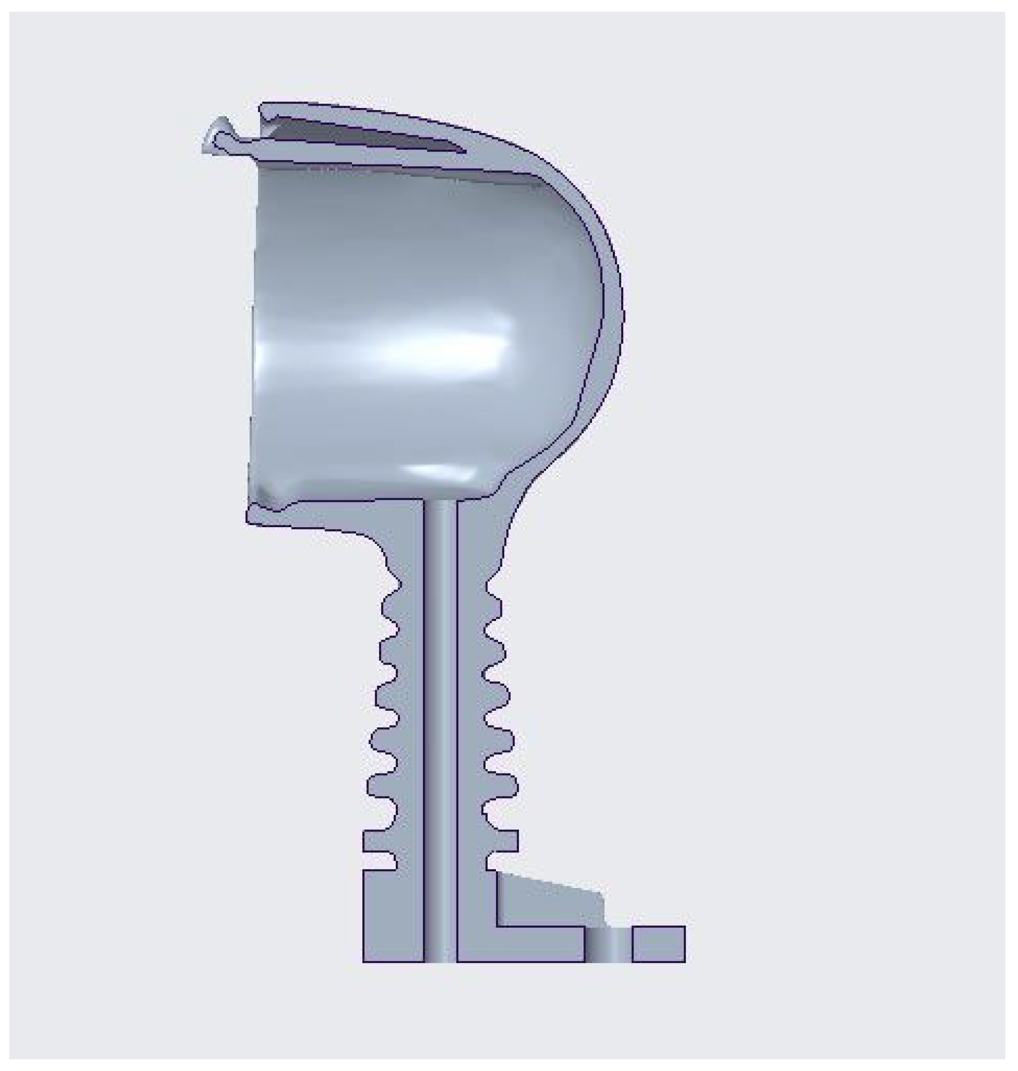
As illustrated in
Figure 5, multiple local geometric deviations were detected on the outer surface of the originally damaged component, particularly in the ribbed section between the upper lamp holder and the lower fastening element. Although the scanning process produced a detailed digital model, additional geometric adjustments were required in the lower region where one of the fractures was located. During the virtual reconstruction of the broken part, temporary support structures became visible in the model and were captured by the scanner as well, necessitating their removal in subsequent CAD steps.
A particularly important zone is the lower contact surface, which fastens the lamp shade to the motor frame. Similar to the previously discussed fracture area, support structures were generated in this region during scanning, causing deviations from the original geometry. Correcting this feature in the CAD model demanded exceptionally high precision, as it constitutes one of the component’s main functional areas, alongside the upper mounting section of the lamp housing. The connection is realized with an M6 screw joint, so an accurate reconstruction of the mounting interface was essential. In addition, slight modifications were carried out on the upper mounting lug, which supports the index cover, as well as on the internal geometry that accommodates the turn signal lamp. These geometric changes did more than simply compensate for scanning errors; they were also intended to re-establish and enhance functional load transfer in the critical regions identified through fracture analysis.
This part describes the physical realisation of a component featuring a complex geometric structure. Because of the part’s intricate shape and the limited production quantity, conventional manufacturing processes were found to be economically impractical. The original part was likely produced by injection moulding; however, the high tooling costs associated with this method could not be justified for a single replacement unit. As a result, additive manufacturing was selected for prototype production, as it offers extensive design freedom and is well-suited for fabricating one-off components.
Table 1 lists the printing parameters: Extrusion temperature, chamber temperature, print speed, and fibre feed rate were controlled by the proprietary Markforged system and were not accessible for user adjustment. These settings reflect the manufacturer-specified nominal values for the chosen materials (Onyx and Kevlar reinforcement).
The continuous fibre-reinforced parts were produced on a Markforged Mark Two 3D printer, (Watertown, MA, USA) using an Onyx thermoplastic as the matrix material in combination with continuous Kevlar fibre reinforcement. Onyx is a nylon-based micro carbon fibre–filled polymer commonly used in composite additive manufacturing due to its favourable stiffness-to-weight ratio, dimensional stability, and printability. Kevlar fibres were selected as the continuous reinforcement material owing to their high damage tolerance and impact resistance, making them suitable for functional components subjected to localized loading and accidental damage
Beyond achieving geometric consistency with the original component, the reconstructed part also had to deliver adequate functional and structural performance under conditions comparable to actual service. To meet these requirements, a continuous fibre-reinforced additive manufacturing process was used to selectively increase the component’s load-bearing capacity. This composite additive manufacturing method allows precise control over both the orientation and positioning of the reinforcing fibres, making it possible to introduce reinforcement only in targeted regions instead of distributing it uniformly throughout the entire geometry.
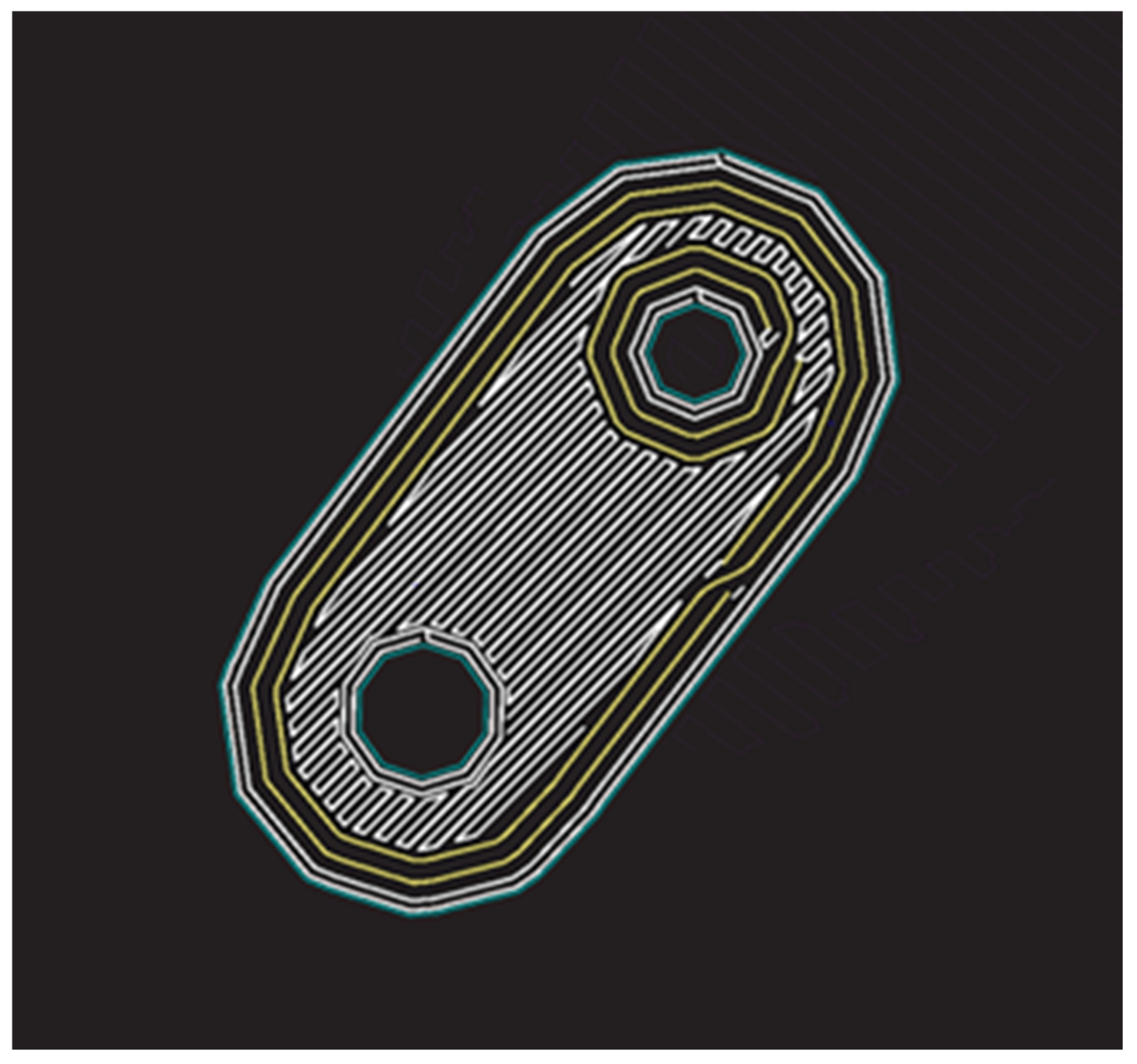
The layout of the fibre reinforcement was determined using qualitative engineering judgement based on observations of the fracture surfaces of the originally damaged component. The reinforcement approach is based on well-established composite design concepts, such as aligning fibres with the inferred load paths, reinforcing areas with high stress concentrations, and seeking to reduce both crack initiation and subsequent crack growth. Specifically, the schematic fibre arrangement shown in
Figure 5 is a direct outcome of the fracture analysis. Zones where crack initiation occurred were given increased reinforcement, and the fibre orientations were chosen to oppose the observed crack propagation direction and to follow the inferred load paths in the component. Areas linked to crack initiation and ultimate failure were identified as structurally critical, and reinforcement was therefore concentrated in these zones, as shown in
Figure 5, where the fibre layout reflects the regions identified as structurally critical based on fracture surface observations. The fibre placement approach was empirical and was not informed by numerical stress analysis or mechanical optimisation. Kevlar fibres were chosen as the reinforcing material because of their favourable impact resistance and damage tolerance, making them appropriate for components exposed to accidental or non-uniform loading conditions.
Fracture surface analyses were employed to qualitatively correlate distinct failure regions with the chosen reinforcement approach. Areas identified as crack initiation points were regarded as zones of heightened stress concentration and reduced structural integrity. As a result, these locations were given priority for fibre reinforcement in the redesigned component.
In addition, the recorded crack growth pattern shed light on the predominant load directions in the structure. The fibre orientations were therefore chosen to roughly oppose these identified load directions, with the goal of enhancing resistance to comparable failure modes.
Figure 6 provides a schematic representation of how the fracture analysis findings were converted into the final reinforcement layout.
The composite additive manufacturing technique allows accurate control of both the orientation and the placement of the reinforcing fibres. Support structures were applied where needed to maintain printing stability. After fabrication, these supports were manually removed without compromising the component’s functional surfaces.
Consequently, reinforcement was focused primarily in the structurally critical zones where the original part had previously experienced failure. Kevlar fibres were selected as the reinforcement due to their advantageous impact resistance and damage tolerance, which makes them well-suited for components.
The precise fibre volume fraction is set by the proprietary slicing software and varies with the chosen reinforcement strategy. Because this parameter is not directly available to the user, it is not explicitly documented in this study.
The chosen parameters and equipment specifications were defined to guarantee practical reproducibility in an industrial reverse engineering setting, rather than to achieve optimisation under laboratory conditions.
The component was manufactured in a print orientation chosen to guarantee structural stability and effective fibre reinforcement in key areas. This orientation aligned the primary load-bearing features with the build plane, thereby enhancing the component’s mechanical performance.
3. Results
The results presented in this section focus on geometric fidelity, functional compatibility, and a qualitative evaluation of the reconstructed component, rather than on its quantitative mechanical behaviour. The reverse engineering and manufacturing workflow that was applied yielded a replacement part with accurate dimensions that remained fully compatible with the original lamp assembly. The final component was produced using a continuous fibre-reinforced additive manufacturing process. No detailed dimensional verification (such as caliper or micrometer measurements) or scan-based deviation analysis was carried out in this work. Consequently, the evaluation of geometric accuracy is limited to a qualitative level. Visual inspection did not indicate any noticeable geometric distortion, surface imperfections, or manufacturing-related anomalies. Nonetheless, it is recognized that visual inspection alone cannot reliably identify minor geometric deviations, internal flaws, or variations in fibre distribution.
The rebuilt component showed complete geometric consistency with the initial assembly, as no misalignment or fit issues occurred during installation. In addition, no visible deformation, delamination, or manufacturing-related flaws were observed in the fabricated part.
The fibre reinforcement was incorporated solely within the interior of the component, while its outer geometry was deliberately kept unchanged to ensure full compatibility with the existing mating interfaces. These design choices were directly guided by fracture surface analyses of the failed original part and were applied at the CAD stage before production.
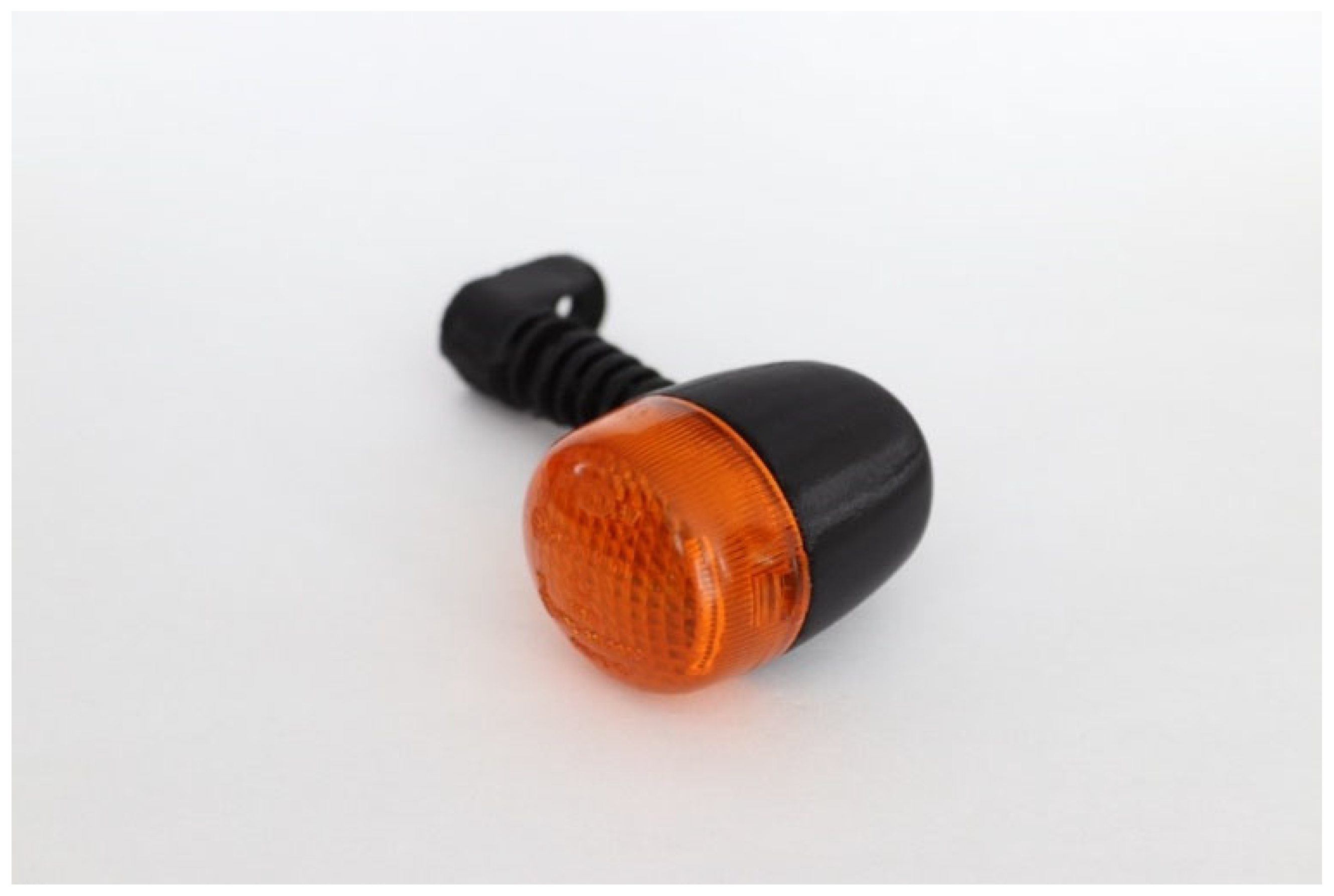
After it was produced, the component was mounted with the lamp housing’s original structural parts. The printed part exhibited accurate dimensional correspondence and proper alignment with the existing yellow lens, confirming that the redesign preserved all critical functional interfaces.
The initial evaluation of performance was limited to assessing geometric fit and verifying functional assembly. No standardized mechanical tests (such as tensile, compressive, or flexural tests) were conducted in this study. Consequently, the findings presented here should be regarded as qualitative confirmation of functional performance, rather than a quantitative assessment of mechanical properties.
As illustrated in
Figure 7, the assembled unit was installed without any modification and operated as intended under standard service conditions. These observations indicate that the redesigned component satisfies the necessary geometric and functional requirements for the application. Nonetheless, no quantitative mechanical tests (such as tensile, flexural, impact, or fatigue evaluations) were conducted in this work. Consequently, the findings presented here should be regarded as qualitative confirmation of fit and functional operation, rather than as a thorough characterization of mechanical performance.
The completed component was evaluated under actual operating conditions. This assessment covered checking the mechanical fit within the overall assembly, confirming the correct alignment of all mounting points, and verifying the component’s stability during installation conditions.
The functional assessment covered checking the mechanical fit, confirming the alignment of the mounting points, verifying structural stability during installation, and evaluating electrical performance by testing the operation of the LEDs.
Furthermore, the system’s electrical functionality was validated by checking LED operation after assembly, confirming that the reconstructed component did not disrupt the electrical connections or the overall performance of the system.
No loosening, misalignment, or functional instability was observed during the test.
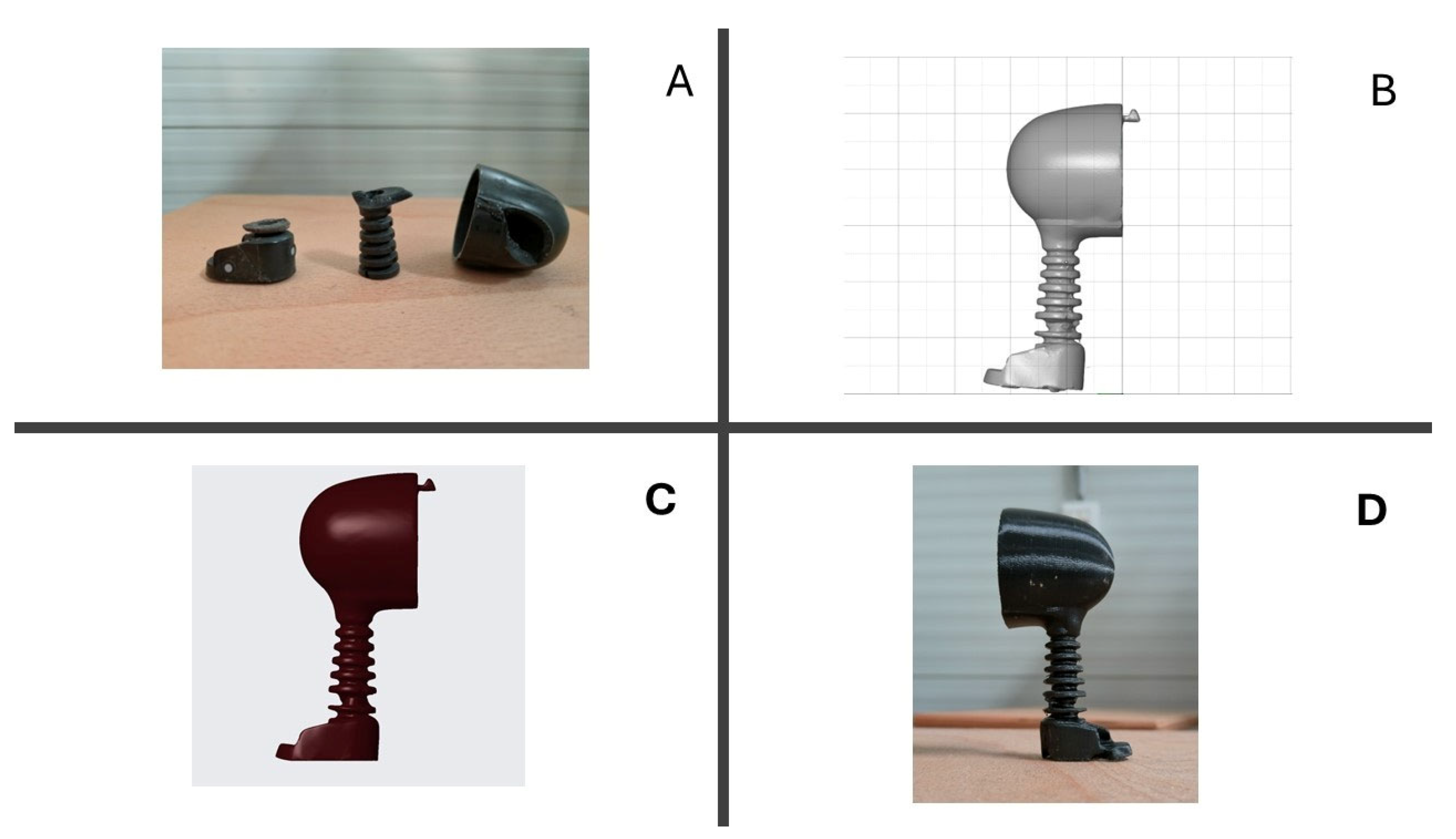
Figure 8 provides an overview of the entire reconstruction workflow. It depicts the key phases of the procedure, starting from the damaged component, followed by the scanned geometry, the reconstructed CAD model, and finally the additively manufactured part. A magnified view of the printed component is included to emphasize important surface characteristics. Thus,
Figure 8 visualizes each step of the full reconstruction process.
4. Discussion
Previous work on reverse engineering has largely concentrated on geometric reconstruction accuracy, mesh manipulation, and dimensional inspection, treating the reconstructed parts chiefly as purely geometric models. By contrast, research on continuous fibre-reinforced additive manufacturing has mainly examined mechanical properties, fibre path optimization, and material behaviour using standardized test coupons, generally without accounting for real fracture histories or undocumented legacy components.
The present study bridges these two areas by directly integrating fracture surface observations from a failed component into the subsequent redesign and reinforcement process. Although the reinforcement approach is not derived from numerical simulations or formal mechanical optimization, it adheres to well-established composite design guidelines, such as orienting fibres along inferred load paths and reinforcing areas linked to stress concentrations. Within this framework, the schematic depiction of fibre reinforcement (
Figure 6) should be viewed as a design-focused abstraction that demonstrates how fracture-based insights were converted into a practical reinforcement concept.
The proposed method offers a practical option for industrial applications where the need for fast reconstruction and the constraints of low production volumes make detailed numerical simulations or extensive experimental studies impractical. Consequently, no finite element simulations or standardized mechanical tests were performed, and the findings should be regarded as providing qualitative, rather than quantitative, confirmation of structural performance.
The fidelity of the reconstructed CAD model depends on the quality of the 3D scanning procedure. Errors can arise from factors such as surface reflectivity, hidden or occluded areas, and noise within the point cloud, all of which can cause geometric discrepancies during mesh creation and reconstruction. Although mesh processing techniques were employed to reduce these issues, their complete removal cannot be assured.
Build orientation is a key factor in the performance of fibre reinforcement because additively manufactured composites exhibit anisotropic behaviour. In this work, the chosen orientation was intended to align the reinforcement with the main load-carrying directions; nonetheless, a non-ideal orientation can diminish the effectiveness of the reinforcement.
From a material standpoint, employing an Onyx matrix reinforced with continuous Kevlar fibres departs from the original polymer part, resulting in differences in stiffness, toughness, and thermal response. Achieving direct material equivalence was not the aim of this work; rather, the intent was to realise comparable functional performance using an alternative material system.
From an economic standpoint, traditional injection molding necessitates the fabrication of a dedicated mold, which entails substantial initial investment, typically from several thousand up to tens of thousands of euros, rendering it unsuitable for low-volume production. By contrast, the additive manufacturing method used here removes the need for tooling altogether, resulting in estimated per-part costs of only tens of euros and thus offering a cost-effective solution for one-off or small-series manufacturing.
While the workflow is illustrated using a single component, it relies on reproducible and broadly accessible procedures, including 3D scanning, CAD reconstruction, fracture-informed design, and additive manufacturing. Consequently, the method can be applied to comparable components, though its suitability is influenced by factors such as geometric complexity, accessibility of fracture surfaces, and specific functional requirements.
Limitations of this study include its dependence on qualitative fracture assessment, the relatively restricted scope of material characterization, and the lack of quantitative validation approaches, such as mechanical testing or numerical simulations. In addition, the success of the reinforcement concept is contingent on accurately interpreting fracture patterns and load paths, which inevitably introduces some subjectivity. Therefore, the approach should be implemented with careful consideration of the specific engineering requirements of each case.
In contrast to earlier studies that concentrate on isolated elements, such as scanning precision or mechanical behavior, this work highlights the combination of several stages into one coherent, application-driven workflow. As a result, the reported reinforcement strategy should be viewed in a qualitative sense, since no quantitative mechanical validation was carried out.
5. Conclusions
This study introduced a comprehensive end-to-end engineering workflow for reproducing a damaged plastic part with intricate geometry, integrating fracture surface analysis, 3D scanning, mesh processing, CAD-based redesign, and continuous fibre-reinforced additive manufacturing. The workflow made it possible to digitally reconstruct a component lacking original design documentation and facilitated deliberate geometric adjustments informed by the identified failure regions.
A central contribution of this study is the use of fracture surface analysis not only as a diagnostic method but also as a direct input for design choices concerning internal geometry changes and the positioning of fibre reinforcements. The reinforcement approach was deliberately localized and based on empirical observations of the original component’s failure behaviour, rather than on numerical optimization or standardized mechanical testing.
The assembly and functional fit tests verified that the redesigned component integrates properly into the original system and performs as intended under typical operating conditions. Together, these results show that the proposed method is effective for restoring both functional performance and geometric compatibility in low-volume, custom, or replacement parts, particularly in situations where conventional manufacturing is not feasible.
The main limitation of this study is the lack of quantitative mechanical testing and the absence of a baseline comparison with the original or non-reinforced parts. As a result, it is not possible to draw firm conclusions about potential gains in mechanical strength, stiffness, or long-term durability. Future research should therefore incorporate standardized mechanical experiments and numerical modeling to quantitatively assess the structural advantages of fracture-analysis-based reinforcement and to support performance claims beyond purely functional validation.
Another limitation of this study is the lack of numerical validation—such as finite element analysis—which could offer more detailed insight into stress distributions and structural behavior. Another limitation of the study is the lack of quantitative geometric validation. Future work should include dimensional measurements and scan-based deviation analysis to assess the accuracy of the reconstructed component.
Future research should therefore encompass standardized mechanical tests on printed specimens, as well as numerical modelling, to validate and refine the structural performance of the proposed design strategy. It must be stressed that these results stem from a qualitative assessment and do not provide strict quantitative validation.