1. Introduction
Gear shaving remains one of the most widely adopted finishing processes for cylindrical gears prior to heat treatment because it offers a favorable balance between productivity, cost, and achievable surface integrity for high-volume applications such as automotive and motorcycle transmissions, reducers, and pumps [
1,
2,
3]. Among common shaving modes (parallel, diagonal, and tangential), plunge shaving is distinguished by a purely radial feed without axial traversing, enabling a short cycle time and simple machine kinematics, which makes it attractive for mass production [
3,
4,
5].
A persistent bottleneck of plunge shaving, however, lies in the manufacturing of the plunge-shaving cutter itself. In theory, the cutter tooth flank exhibits a hyperboloid-like geometry in the lead direction and often requires prescribed topological modifications—such as crowning and bias—to achieve the desired contact pattern and to mitigate noise and sensitivity to misalignment [
4,
5,
6,
7,
8,
9]. This combination of complex spatial geometry and stringent modification requirements makes plunge-shaving cutters considerably more difficult to manufacture and inspect than conventional shaving cutters, and the cutter’s manufacturing deviations may directly propagate to the work-gear tooth surface. On the analytical side, Radzevich [
10] proposed a methodology for designing a shaving cutter to plunge-shave a topologically modified involute pinion, while Seol and Litvin [
11] and Klocke and Schroder [
12] presented computerized simulations of the gear shaving process, providing important insights into the meshing kinematics and material-removal mechanisms. It should be noted that these studies primarily address the design and meshing simulation of the shaving process, whereas the present work focuses on the upstream manufacturing problem of producing the cutter itself with controlled topographic accuracy. The two lines of research are complementary: the cutter design models provide the target geometry, while the present framework addresses how to realize that geometry through generative grinding with quantified error control.
The most commonly used manufacturing route for plunge-shaving cutters is generative grinding using a cone grinding wheel, as exemplified by dedicated CNC machines such as the Gleason–Hurth SRS 410 [
13]. In this process, the cutter surface is produced through enveloping motion between the grinding wheel and the cutter blank. Nevertheless, cone-wheel-based generation can be relatively slow and may introduce systematic topographic deviations when the machine setting and tool geometry are not perfectly matched. Hsu and Fong [
14] quantified such deviations by analyzing the topographic error of a plunge-shaving cutter finished by a cone grinding wheel, highlighting the bias- and twist-type errors that may arise in practice; a more detailed account of the underlying cutter design methodology is provided in [
15]. These observations motivate the development of a faster and more controllable generation process with an explicit error-correction mechanism. In related work, Chang et al. [
16] simulated shaving machine kinematics and performed tooth contact analysis, while Hung et al. [
17] investigated the effects of cutter assembly errors and machine-setting parameters on the resulting shaved gear topography, further underscoring the sensitivity of the process to manufacturing variables.
The recent literature reveals two major research directions in this field: computerized tool design and simulation for plunge shaving, and precision measurement with error governance for complex cutter tooth surfaces. On the design side, Cao and Li [
18] developed a computerized framework for plunge-shaving tools based on beveloid gears and validated the associated shaving characteristics through simulation. Li et al. [
19] proposed a dedicated measurement method that accounts for the land features of plunge-shaving cutters, improving metrological robustness on discontinuous tooth surfaces. On the manufacturing side, the grinding worm has attracted increasing attention as a high-efficiency approach for generating gear tooth flanks. Zhou et al. [
20] and Yan et al. [
21] demonstrated closed-loop compensation strategies for worm-based generation of face gears, while Jiang et al. [
22] reported a mapping-based error identification method that relates measured tool surfaces to the resulting tooth-flank deviations. Furthermore, the recent literature from 2023 to 2025 has increasingly emphasized the stringent noise, vibration, and harshness (NVH) requirements of modern electric vehicles [
23,
24], which pushes the boundaries of continuous generating gear grinding through multi-axis CNC kinematics [
25,
26]. To achieve such high manufacturing precision, the integration of robust digital modeling and optimization algorithms has become a vital trend to ensure the validity and accuracy of complex tooth surface error compensation [
27,
28]. Despite these advances, no dedicated framework has been reported that applies grinding-worm generation specifically to plunge-shaving cutters together with a parameterized topographic error correction strategy suitable for industrial implementation.
This paper presents a comprehensive mathematical modeling and manufacturing-error correction method for plunge-shaving cutters generated by a grinding worm. First, the theoretical cutter tooth surface is derived using envelope theory and homogeneous coordinate transformations, leading to a kinematic model of the generative grinding process. Second, an optimization algorithm based on linear least squares is developed to identify an optimal center-distance compensation that minimizes the residual topographic error between the ground surface and the theoretical design. Third, the influence of key parameters—including the worm helix angle and cutter helix angle—on the achievable error suppression is analyzed. Finally, three numerical examples are provided, including a benchmark comparison against the cone-grinding-wheel approach. A preliminary version of the kinematic model was presented in [
29]; the present work substantially extends that study by
- (i)
Developing a linearized least-squares compensation framework;
- (ii)
Introducing worm-helix-angle tuning as a second-level optimization;
- (iii)
Providing three numerical case studies, including a benchmark comparison.
2. Mathematical Modeling of a Standard Involute Helical Gear
This section briefly summarizes the rack-generation formulation for an involute helical gear, which is used to define the theoretical work-gear surface for the subsequent cutter conjugation model. The derivation follows the classical theory of gearing and envelope generation [
1,
11].
2.1. Rack Cutter Surface Parameters
A local coordinate system,
, is attached to the rack cutter. The position vector,
, and the unit normal vector,
, of a point on the cutter surface are represented as functions of the surface parameters,
and
:
2.2. Coordinate Transformation of Generation Motion
According to Litvin’s theory [
1], the relative motion between the cutter and the gear blank is described using homogeneous transformation matrices. Let coordinate system
be attached to the gear blank. The generation process simulates pure rolling, involving two coupled degrees of freedom: the rotation of the blank,
, and the translation of the rack,
. The relationship is
, where
is the pitch radius of the gear. To generate a helical gear with a helix angle,
, the cutter is tilted. The transformation matrix,
, from
to
is
In
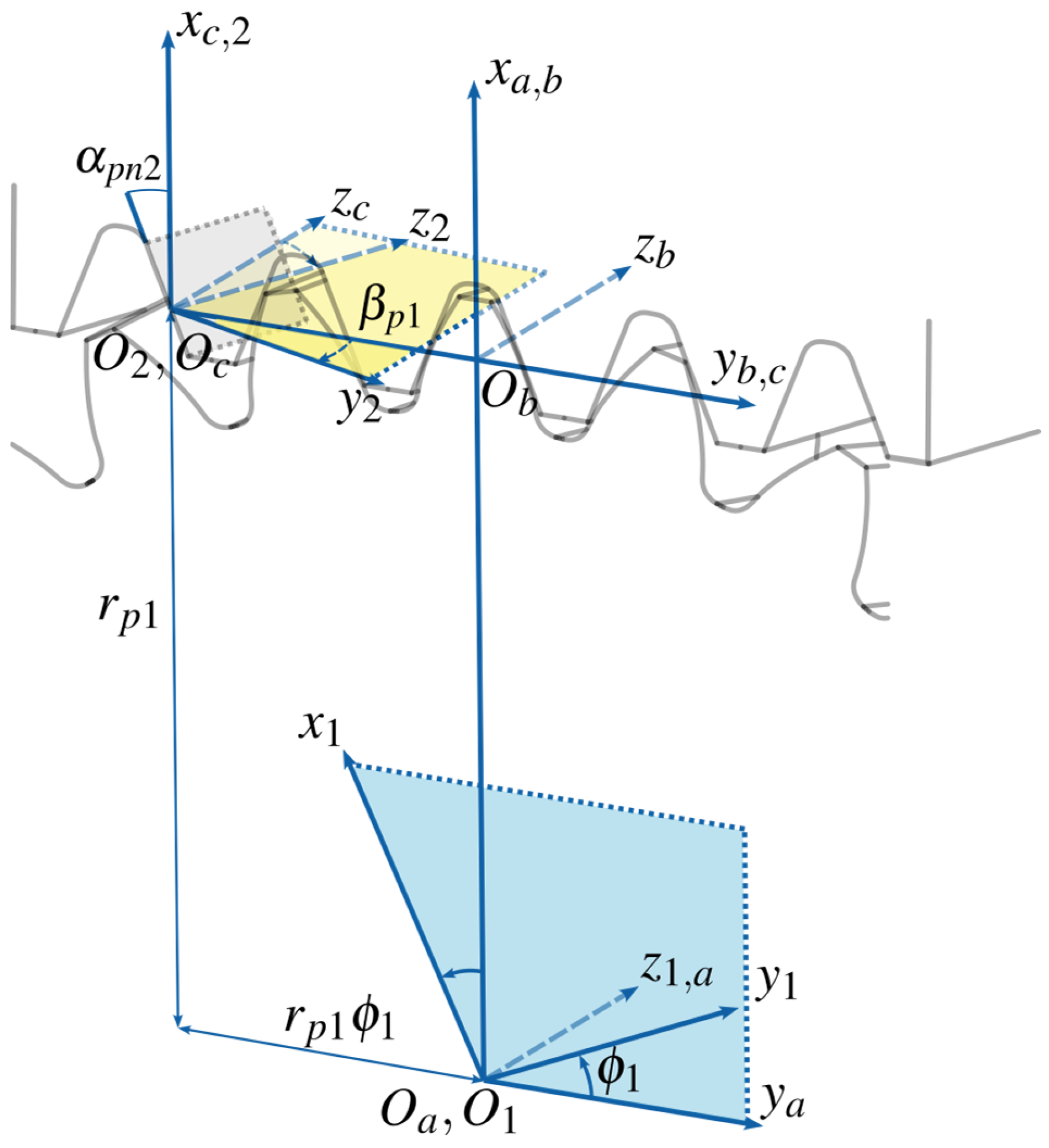
Figure 1, the origins of all coordinate systems involved in the rack-gear generation are labeled to indicate their spatial positions. The auxiliary coordinate systems
,
, and
serve as intermediate frames that decompose the transformation from
(rack cutter) to
(gear blank) into sequential steps:
accounts for the helix-angle tilt of the rack cutter,
represents the translational motion of the rack,
describes the offset by the pitch radius
, and
represents the gear-blank rotation by
.
The expanded form of the homogeneous transformation matrix is
While the full motion is represented by the homogeneous matrix,
, to analyze the orientation of the coordinate axes and transform the vector components (such as surface normals), we extract the upper-left
rotation submatrix, denoted as
. The derived matrix is expressed as follows:
2.3. Family of Surfaces and Equation of Meshing
The locus of the cutter surface represented in coordinate system
, known as the family of surfaces, is determined by
The corresponding normal vector transforms as
The envelope of this family of surfaces must satisfy the equation of meshing, which states that the normal vector must be perpendicular to the relative velocity vector,
, at the contact point:
By solving Equations (4)–(8) simultaneously, the theoretical involute gear surface is determined.
3. Mathematical Model of the Theoretical Tooth Surface of the Plunge-Shaving Cutter
This section derives the theoretical tooth surface of a plunge-shaving cutter that is conjugate to a target involute helical work gear. The cutter surface is obtained as the envelope generated by the work-gear tooth surface under a crossed-axis meshing configuration with a fixed operating center distance and shaft angle. The resulting theoretical cutter geometry serves as the reference surface for the subsequent manufacturing model (
Section 4) and topographic error evaluation (
Section 5 and
Section 6).
3.1. Coordinate Systems and Operating Parameters
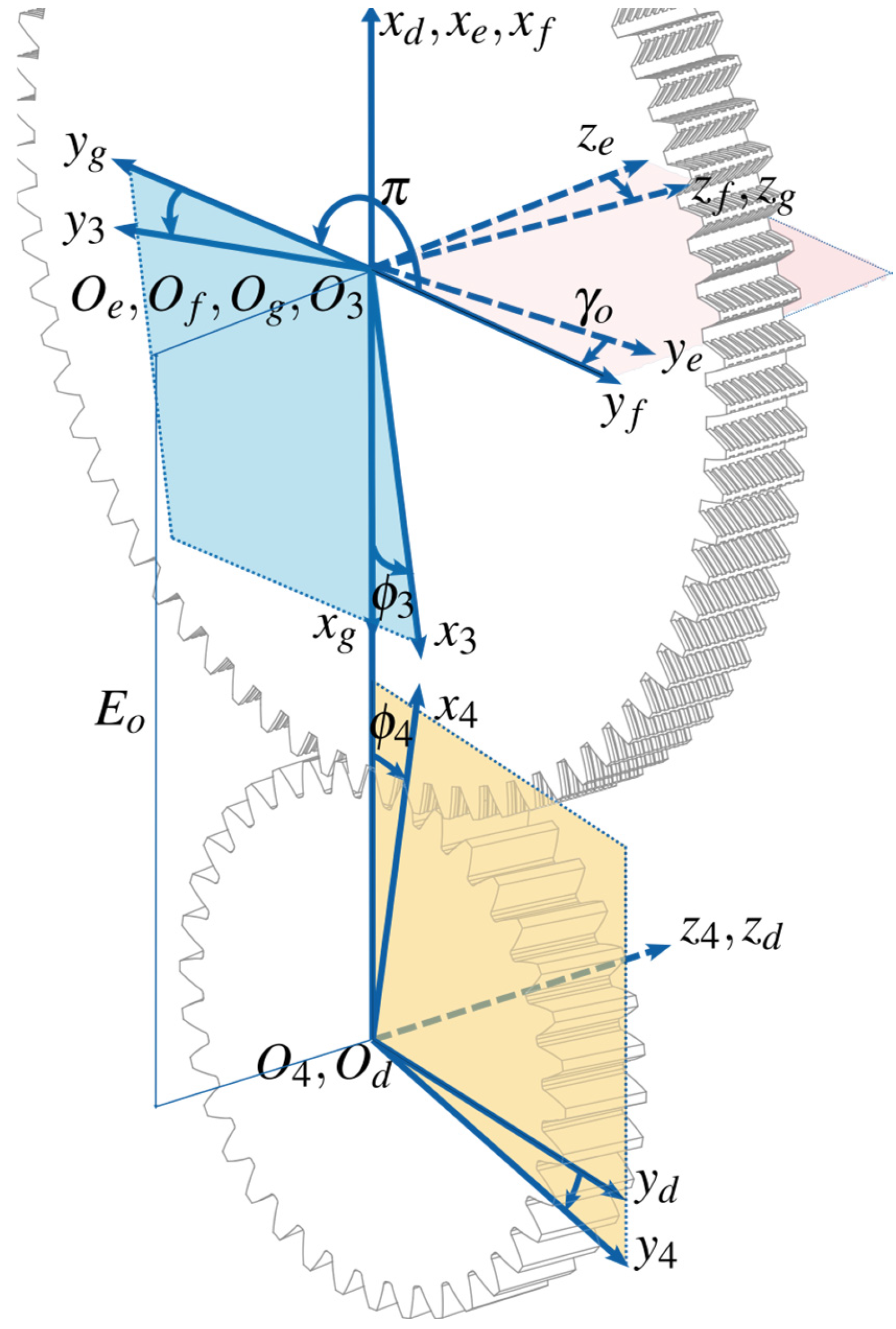
Figure 2 illustrates the kinematic relationship between the work gear and the plunge-shaving cutter. Two moving coordinate systems are attached to the rotating bodies.
: A movable coordinate system rigidly attached to the work gear. The -axis coincides with the rotation axis of the work gear.
: A movable coordinate system rigidly attached to the plunge-shaving cutter. The -axis coincides with the rotation axis of the cutter.
: Auxiliary fixed coordinate systems used to describe the spatial relationship (center distance and shaft angle) between the cutter and the work gear.
The operating parameters for the plunge-shaving process are defined as:
It is noted that the auxiliary coordinate systems in
Figure 1 (
,
, and
) and those in
Figure 2 (
,
,
, and
) are placed differently because they serve fundamentally different kinematic configurations. In the rack-gear generation of
Section 2, the auxiliary frames lie along the pitch plane where the rack and gear are in tangential contact. In the crossed-axis meshing model of
Section 3, the auxiliary frames must describe the spatial relationship between two skew axes separated by a center distance,
, and a shaft angle,
, and are accordingly placed along the common normal and at the respective rotation axes.
3.2. Coordinate Transformation for Crossed-Axes Meshing
Let the theoretical involute work-gear tooth surface be expressed in
as
, where
and
are the surface parameters. To determine the conjugate cutter surface, this work-gear surface is mapped into the cutter coordinate system,
, via the homogeneous transformation matrix,
. The homogeneous coordinate transformation from
to
is expressed as
The homogeneous transformation matrix,
, is derived as the product of the component matrices representing these sequential motions:
where:
and represent the rotation of the work gear and the shaving cutter about their respective axes ( and ).
represents the translation along the common normal by the center distance, .
accounts for the shaft angle, , between the cutter and the work gear axes.
is a coordinate orientation matrix (rotation by around the -axis) applied to align the cutter’s axis properly.
The rotation angles and are related by the constant gear ratio . By performing the matrix multiplication, the final transformation matrix, , is obtained and used for the subsequent surface generation.
3.3. Equation of Meshing and Surface Determination
The theoretical cutter surface is obtained as the envelope of the transformed work-gear surface family. Therefore, the meshing condition requires that the surface normal at the contact point be orthogonal to the relative velocity. The equation of meshing is more conveniently expressed as the scalar product of the normal vector,
, and the partial derivative of the position vector with respect to the motion parameter,
:
where the normal vector in the cutter system,
, is obtained by transforming the work gear normal,
using the
rotation submatrix,
(extracted from
):
By simultaneously solving the position equation and the equation of meshing derived above, the set of parameters
that defines the theoretical cutter surface is determined. The resulting surface is expressed as
This mathematical model provides the exact theoretical geometry of the plunge-shaving cutter required to generate the target involute work gear.
4. Mathematical Model of Generative Grinding with Worm
This section presents a generative grinding model for manufacturing a plunge-shaving cutter using a grinding worm. The ground cutter tooth flank is treated as the envelope of a family of worm surfaces swept under a crossed-axis configuration. The machine setting is characterized by a prescribed axial feed motion and a controlled operating center distance, which is used to introduce longitudinal crowning. The resulting model provides a direct linkage between machine settings, worm geometry, and the generated cutter topography, and it serves as the basis for the center-distance compensation strategy described in
Section 5.
4.1. Coordinate Systems and Kinematics
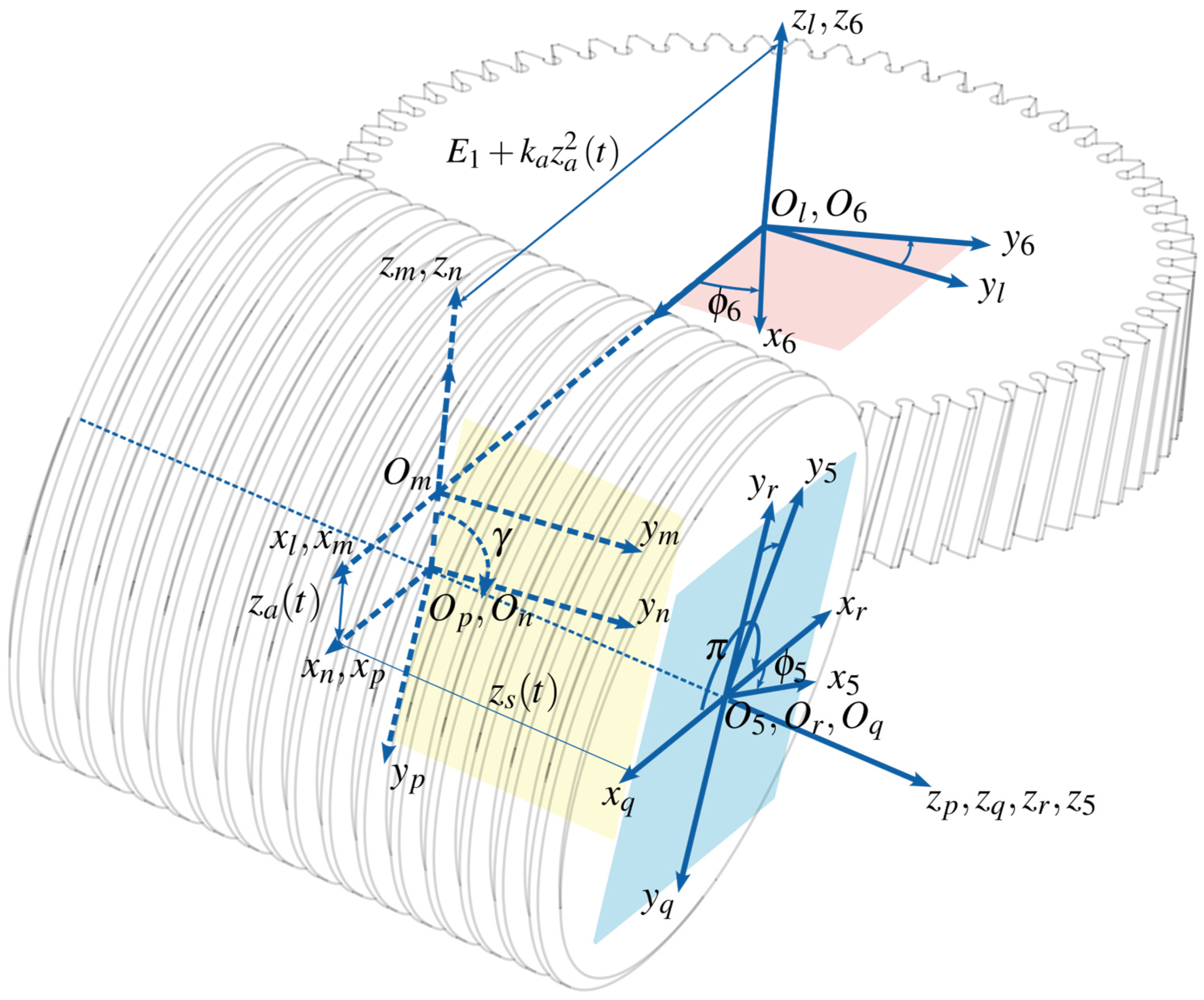
To describe the machine kinematics (
Figure 3), the following coordinate systems are defined:
: A moving coordinate system rigidly attached to the grinding worm. The -axis coincides with the worm rotation axis.
: A moving coordinate system rigidly attached to the plunge-shaving cutter (workpiece). The -axis coincides with the cutter rotation axis.
: The auxiliary coordinate systems used to describe intermediate machine settings and relative motions.
The key process parameters include the worm rotation angle,
; the cutter rotation angle,
; the shaft angle,
; and the axial feed coordinate,
. To introduce longitudinal crowning, the operating center distance is prescribed as a parabolic function of the axial feed:
where
is the nominal center distance (at
), and
is the parabolic crowning coefficient.
Figure 3.
Coordinate systems for the generative grinding process with a worm. The colored planes indicate the planes of rotation involved in the transformations.
Figure 3.
Coordinate systems for the generative grinding process with a worm. The colored planes indicate the planes of rotation involved in the transformations.
4.2. Surface Geometry of the Grinding Worm
The grinding worm is modeled as an involute helicoid. In its local coordinate system,
, the worm surface is parameterized by (
), where
denotes the profile (involute-roll) parameter, and
denotes the axial parameter along the worm thread. The position vector,
, and unit normal vector,
, are defined as
4.3. Coordinate Transformation for Generative Grinding
To obtain the locus of the worm surface in the cutter coordinate system,
, the worm surface is mapped through a homogeneous transformation matrix,
, which accounts for the worm rotation, axial feed; crossed-axis setting; variable center distance,
; and the cutter rotation:
In implementation, the worm surface and its normal vector in
can be obtained as
where
is the
rotation submatrix extracted from
.
The physical meaning of the component matrices in Equation (17) is summarized as follows:
: Worm rotation by ;
: Orientation flip (rotation by ) for axis alignment;
: Axial translation of the worm along its axis (denoted as in the original kinematic chain);
: Rotation corresponding to the shaft angle, ;
: Translation along the common normal by the variable center distance, ;
: Cutter rotation by .
4.4. Kinematic Relationship
During generation, the worm rotation and cutter rotation are coupled. In addition, the axial feed,
, introduces an auxiliary rotation component to ensure the correct lead and helix angle on the cutter flanks. Assuming a constant transmission ratio, the cutter rotation angle,
, is related to the worm rotation angle,
, and the axial feed,
, as
where
and
are the number of threads of the grinding worm and the number of teeth of the plunge-shaving cutter, respectively;
is the standard pitch helix angle of the grinding worm; and
is the standard pitch radius of the shaving cutter.
4.5. Equations of Meshing and Determination of the Ground Cutter Surface
The worm-ground cutter surface is defined as the envelope of the transformed worm surface family. Because the process contains two independent motion parameters (worm rotation,
, and the axial feed,
), two independent meshing conditions must be satisfied simultaneously. These conditions enforce orthogonality between the worm surface normal and the relative velocity associated with each motion parameter:
Solving the surface mapping (
Section 4.3), the kinematic relationship (Equation (17)), and the two meshing equations (Equations (20) and (21)) yields the set of contact points that forms the theoretical tooth surface of the worm-ground plunge-shaving cutter in
. The resulting topography explicitly reflects the crossed-axis geometry and the prescribed center-distance modification,
, for crowning.
5. Optimization via Center Distance Compensation
To reduce the systematic topographic error introduced by the generative grinding process, an optimization strategy based on machine-setting compensation is adopted. Since the profile accuracy in the vicinity of the operating pitch cylinder is most critical to the subsequent shaving performance, the objective is to minimize the normal deviation of the worm-ground cutter surface in this region.
In the proposed approach, the parabolic coefficient, , in the center-distance function, (see Equation (14)), is selected as the control variable. The effect of a small adjustment, , on the surface topography is quantified through a sensitivity analysis, and a linear least-squares update is applied to determine the optimal, .
A set of
discrete grid points is selected on the operating pitch cylinder of the theoretical shaving cutter surface. At each grid point
, the normal deviation is computed as the projection of the position difference between the worm-ground surface and the theoretical surface onto the theoretical unit normal:
where
and
denote the position vectors of the worm-ground surface and the theoretical cutter surface, respectively, and
is the unit normal vector of the theoretical surface at point
.
To relate the deviation to the machine-setting parameter,
, the sensitivity coefficient,
, is defined as the rate of change of
with respect to
. In practice,
is evaluated numerically by a finite difference:
Assuming a first-order linearization, the updated deviation vector can be written as , where and .
The least-squares problem is then formulated as minimizing
, which yields the following normal equation:
and the optimal update is obtained as
Finally, the compensated machine setting is updated by and substituted back into the center-distance function, (Equation (14)). As a result, the topographic error on the operating pitch cylinder is reduced in a least-squares sense, effectively mitigating the systematic bias of the worm-ground cutter surface.
In this study, the deviation vector, , is evaluated on a discrete grid defined on the operating pitch cylinder of the theoretical cutter surface. A total of k = 45 points are used on a single flank, obtained by sampling nine equally spaced locations along the face-width direction and five points along the tooth-profile direction at each face-width location (i.e., a 9 × 5 grid). Although the face width of the plunge-shaving cutter differs from that of the work gear, the same 9 × 5 sampling scheme is adopted as a fixed discretization strategy for the compensation analysis. This grid was selected to provide sufficient spatial resolution for capturing the dominant low-order topographic deviations, primarily twist and crowning, while maintaining computational efficiency. The sensitivity coefficients, , are computed by a finite-difference perturbation of (Equation (23)) using a sufficiently small to ensure first-order linearity. Because the normal equation (Equation (25)) involves only a single scalar unknown, the optimal is obtained in closed form, and no iterative procedure is required. The validity of the first-order linearization was verified numerically: the computed remained well within the linear regime of the sensitivity coefficients in all three examples, confirming the stability of the solution. The linear least-squares formulation was selected because the present compensation problem involves only a single parameter. Under this condition, the first-order sensitivity model provides sufficient accuracy, and the resulting closed-form scalar solution avoids the computational overhead and tuning requirements of iterative nonlinear methods such as Levenberg–Marquardt or genetic algorithms. Should multi-parameter compensation be pursued in future work (e.g., simultaneous optimization of and ), a nonlinear optimization framework would then become necessary. For larger tooth surfaces, the grid density can be straightforwardly increased without modifying the compensation algorithm since the least-squares formulation in Equation (25) is valid for an arbitrary number of evaluation points, k.
6. Numerical Examples and Analysis
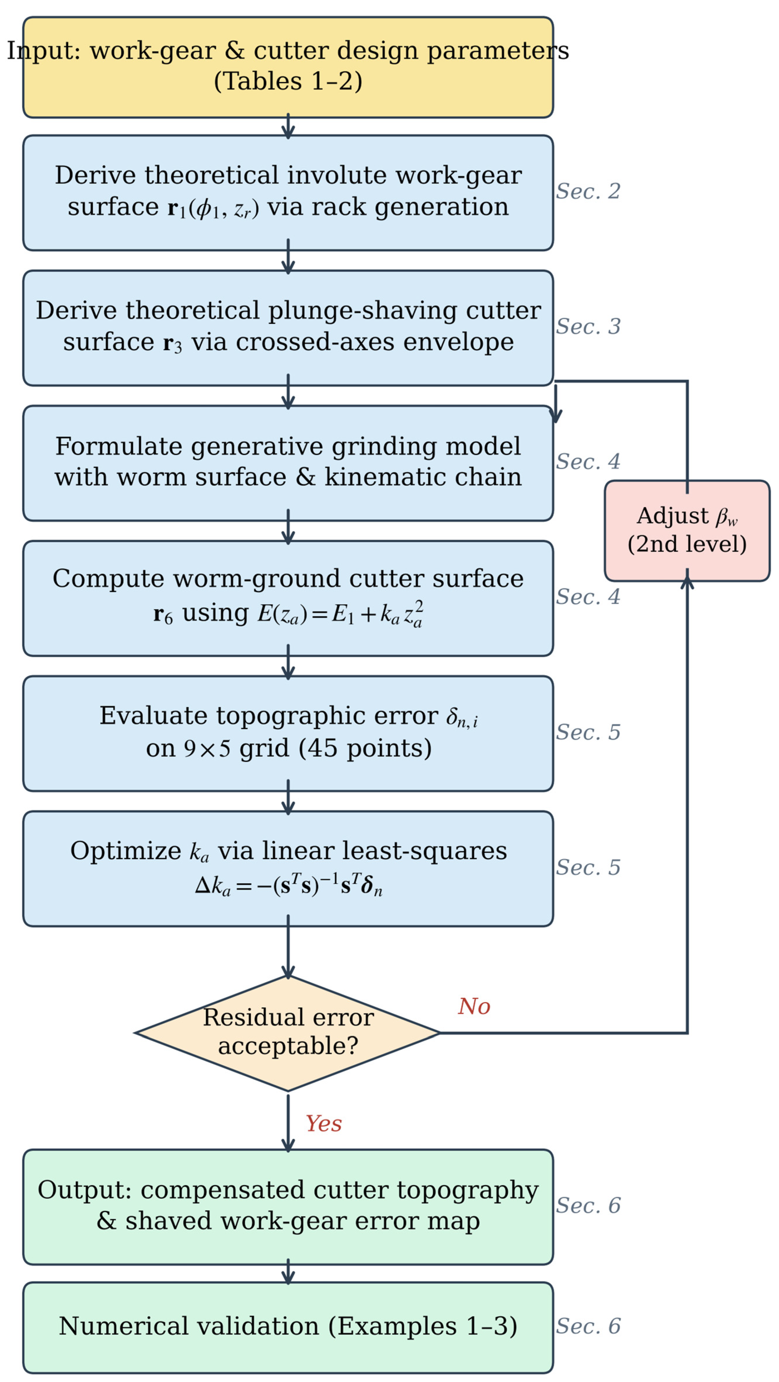
Figure 4 presents a flowchart summarizing the overall methodology of this study. The process begins with the input of work-gear and cutter design parameters (
Table 1 and
Table 2), followed by the derivation of the theoretical work-gear surface (
Section 2) and the conjugate cutter surface (
Section 3). The generative grinding model (
Section 4) then computes the worm-ground cutter surface using the parabolic center-distance function,
. The topographic error is evaluated on a
grid, and the compensation parameter,
, is optimized via the linear least-squares method (
Section 5). If the residual error remains unacceptable, a second-level optimization adjusting the grinding-worm helix angle,
, is performed.
This section validates the proposed generative grinding model (
Section 4) and the center-distance compensation strategy (
Section 5) through numerical case studies. The evaluation focuses on two aspects:
- (i)
The topographic error of the ground shaving-cutter surface with respect to the theoretical conjugate cutter surface (
Section 3);
- (ii)
The resulting topographic error map of the shaved work-gear flank, which represents the ultimate functional verification of the cutter.
To enable a fair benchmark, Example 1 adopts the same geometric parameters and operating conditions reported in the reference study by Hsu and Fong [
14], where the cutter was finished by a cone grinding wheel. The proposed method replaces the cone wheel with an involute-helicoid grinding worm and applies a single-parameter compensation through the parabolic center-distance function,
(Equation (14)). Unless otherwise stated, the compensation parameter,
, is obtained by the least-squares procedure in
Section 5, which minimizes the normal deviation on the operating pitch cylinder.
6.1. Example 1: Benchmark Comparison with a Moderate Helix Angle
This example uses the exact geometric parameters from the benchmark literature to ensure a consistent comparison. The system consists of an involute work gear and a plunge-shaving cutter with the operating conditions listed in
Table 1.
Unlike the reference method based on a cone grinding wheel, this study employs a grinding worm modeled as an involute helicoid. The parabolic coefficient,
, in
is optimized by the least-squares method (
Section 5) to minimize the deviation at the operating pitch cylinder.
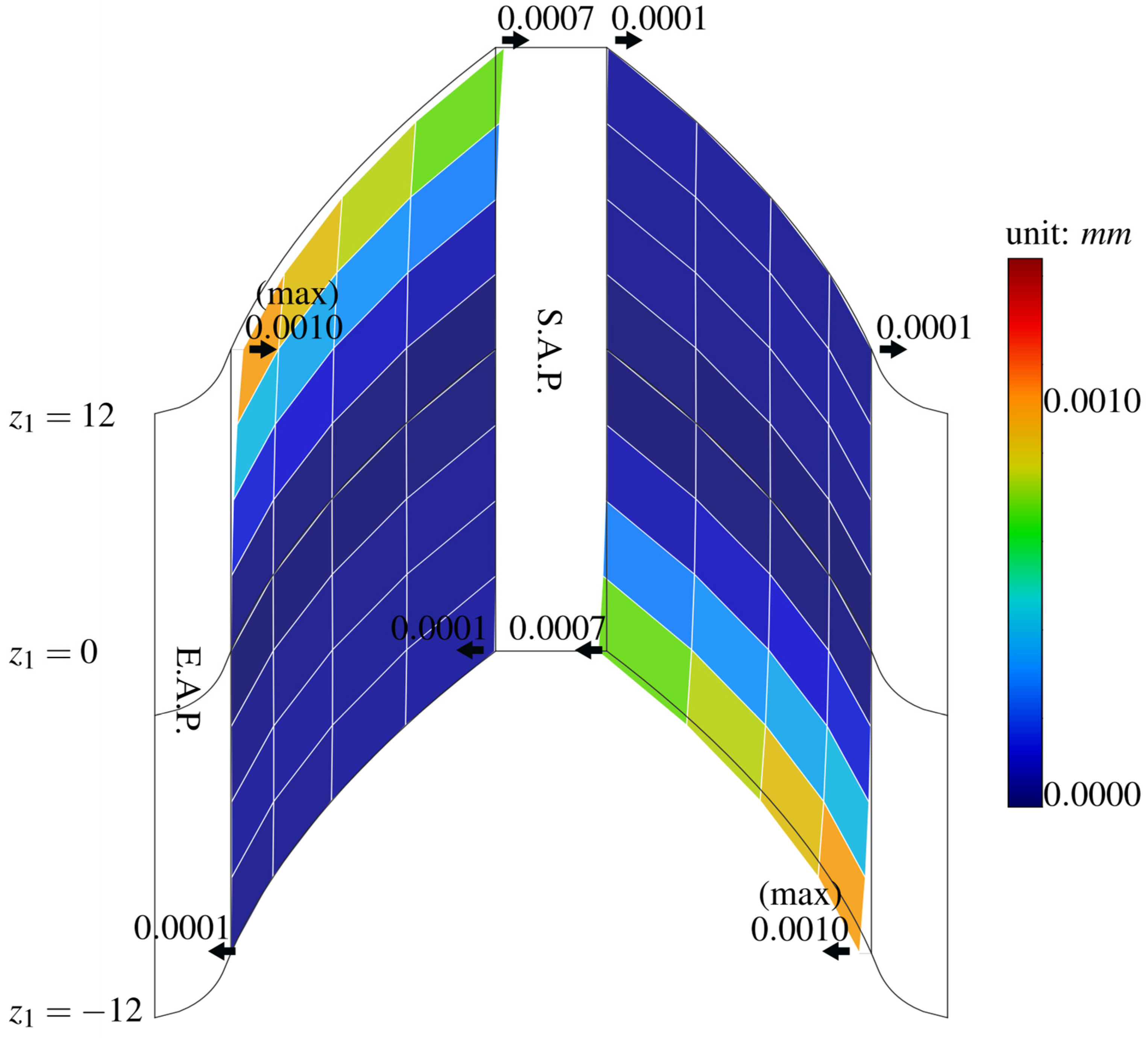
Figure 5 shows the computed topographic error of the worm-ground shaving cutter relative to the theoretical cutter surface. The deviation is effectively controlled around the active region bounded by the start of active point (S.A.P.) and the end of active point (E.A.P.), and the residual error is distributed in a relatively uniform manner over the flank.
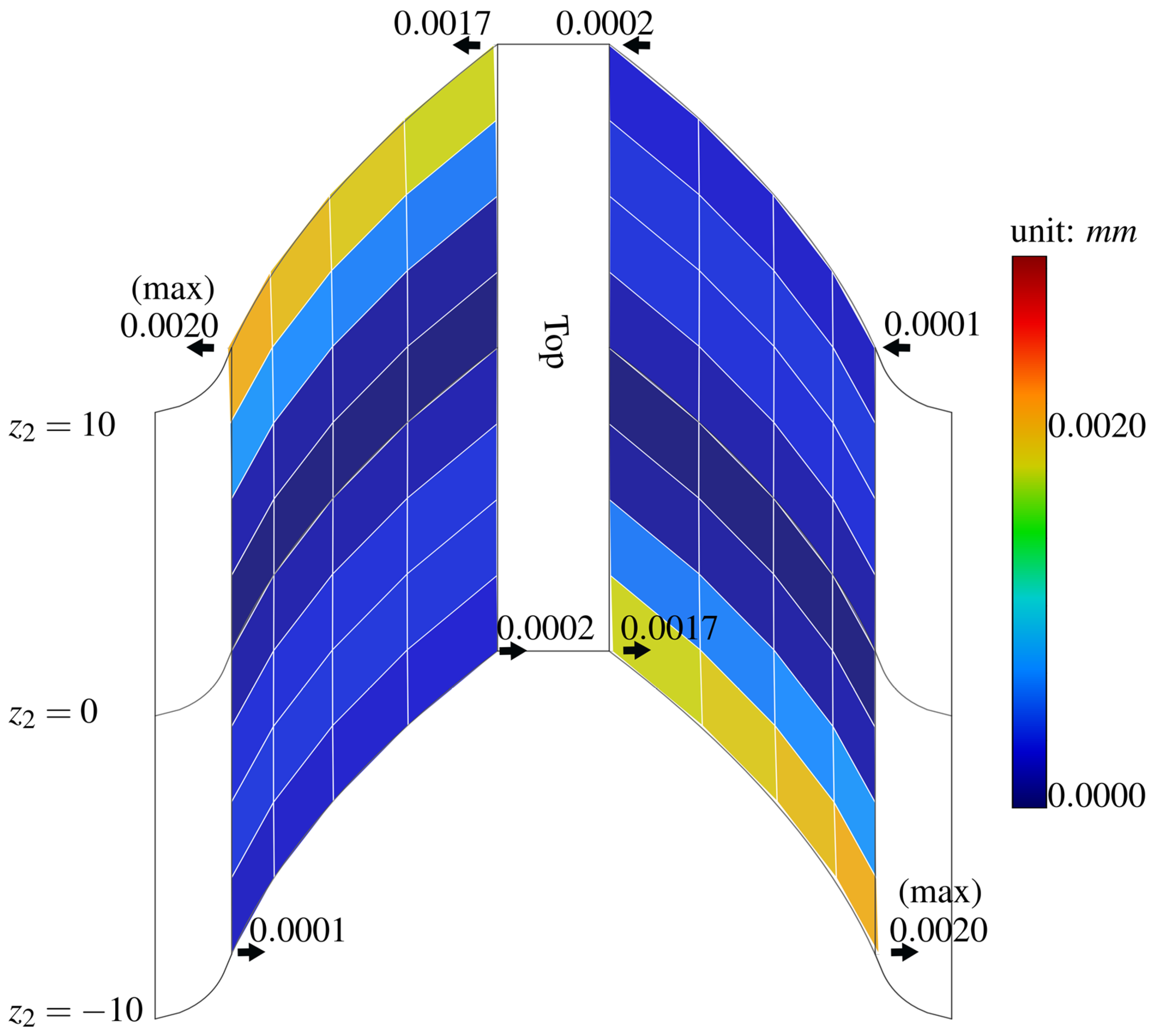
The functional performance is assessed by the topographic error of the shaved work gear. The error map of the work-gear flank generated by the proposed cutter is shown in
Figure 6. The maximum absolute normal deviation is approximately 2 µm. Compared with the benchmark results reported for cone-wheel finishing, the characteristic diagonal bias (natural twist) is markedly suppressed, indicating that the single-parameter compensation through
is effective for mitigating twist-related topographic errors in crossed-axis plunge shaving. Regarding the validity and accuracy of the numerical calculations in this benchmark case, all spatial coordinate transformations and envelope conditions were implemented using double-precision floating-point arithmetic. This ensures that numerical truncation errors are negligible compared to the micron-level topographic deviations. Furthermore, the
discretization grid provided sufficient numerical stability for the linear least-squares compensation, yielding a strictly convergent
without matrix singularity.
6.2. Example 2: Validation with a Large Helix Angle (Reverse Helix)
To examine robustness under a more challenging geometry, Example 2 modifies the helix angle of the plunge-shaving cutter while maintaining the same center distance and shaft angle setting as in Example 1. The detailed parameters are listed in
Table 2. In conventional cone-wheel finishing, increasing the magnitude of the cutter helix angle typically aggravates topographic error due to the geometric mismatch between the tool envelope and the target lead-curvature of the cutter surface. This case, therefore, provides a demanding test of the proposed worm-based generative grinding and compensation approach.
The simulation is carried out using the proposed model with the optimized compensation parameter, . Despite the increased helix-angle magnitude and the helix-direction reversal, the generated cutter topography remains stable, and the twist-like bias is not amplified.
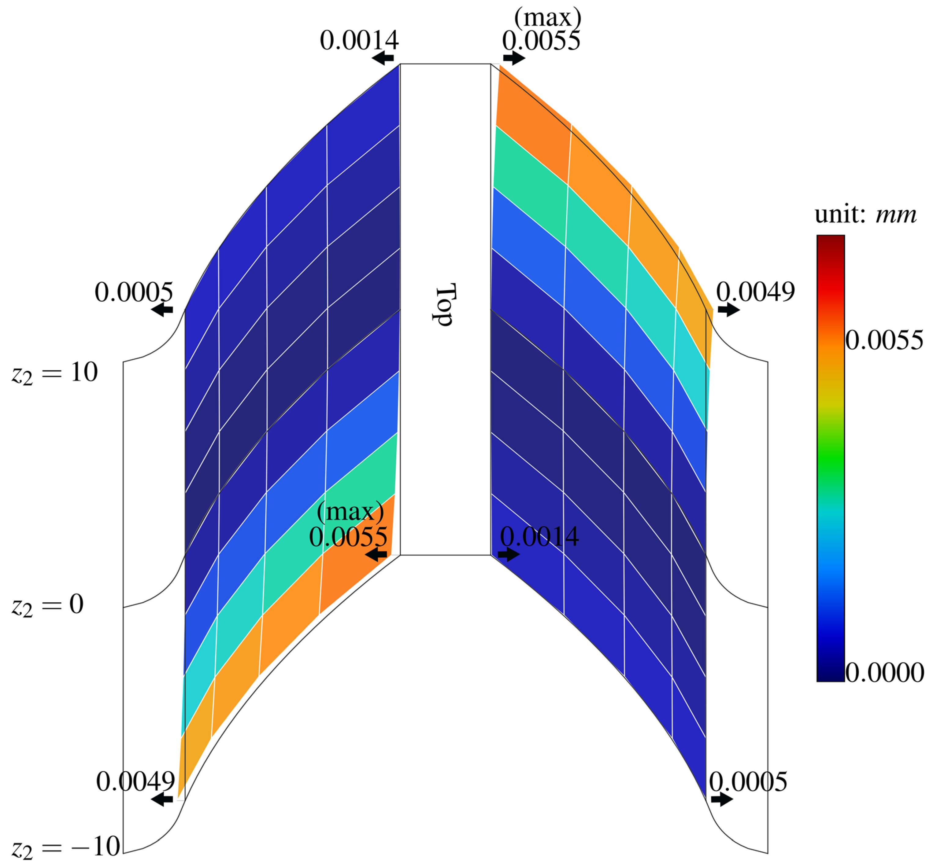
The topographic error map of the shaved work gear is shown in
Figure 7, where the maximum normal deviation reaches approximately 5.5 µm under this large-helix configuration. This observation indicates that center-distance compensation alone may be insufficient to fully eliminate localized peaks when the envelope-generation condition becomes more demanding. Therefore, in Example 3, we further improve the result by modifying the grinding-worm geometry parameters, which provides an additional degree of freedom to reshape the swept envelope and reduce the residual topographic error. For this large-helix configuration, the accuracy of the calculations is well maintained despite the significantly increased twist deviation. The sensitivity coefficients,
, computed via finite-difference perturbation, remained mathematically robust. The numerical stability of the normal equation (Equation (24)) was continuously monitored during the simulation, confirming that the single-parameter optimization accurately captures the error gradient without numerical instability even under demanding envelope-generation conditions.
6.3. Example 3: Further Improvement by Modifying the Grinding-Worm Helix Angle
The results in
Figure 7 show that, under the large-helix configuration (Example 2), center-distance compensation alone can still leave localized peak deviations on the shaved work-gear flank (with a maximum deviation of approximately 5.5 µm). To further reduce this residual error, Example 3 introduces a second-layer optimization by adjusting the grinding-worm helix angle.
In this example, the work-gear and cutter designs, as well as the kinematic framework of the generative grinding process, are unchanged. Only the grinding-worm helix angle is modified from
(Example 2) to
(Example 3), as summarized in
Table 3. For the modified worm configuration, the compensation coefficient,
, is re-identified using the same least-squares procedure described in
Section 5 to ensure a fair comparison.
It is noted that the helix-angle adjustment of approximately 0.345° (from 89.345° to 89°) lies well within the control capability of modern CNC worm-dressing processes, where sub-degree helix-angle changes are routinely achievable. Such adjustments are commonly explored in industrial practice to fine-tune the generation characteristics for specific workpiece geometries.
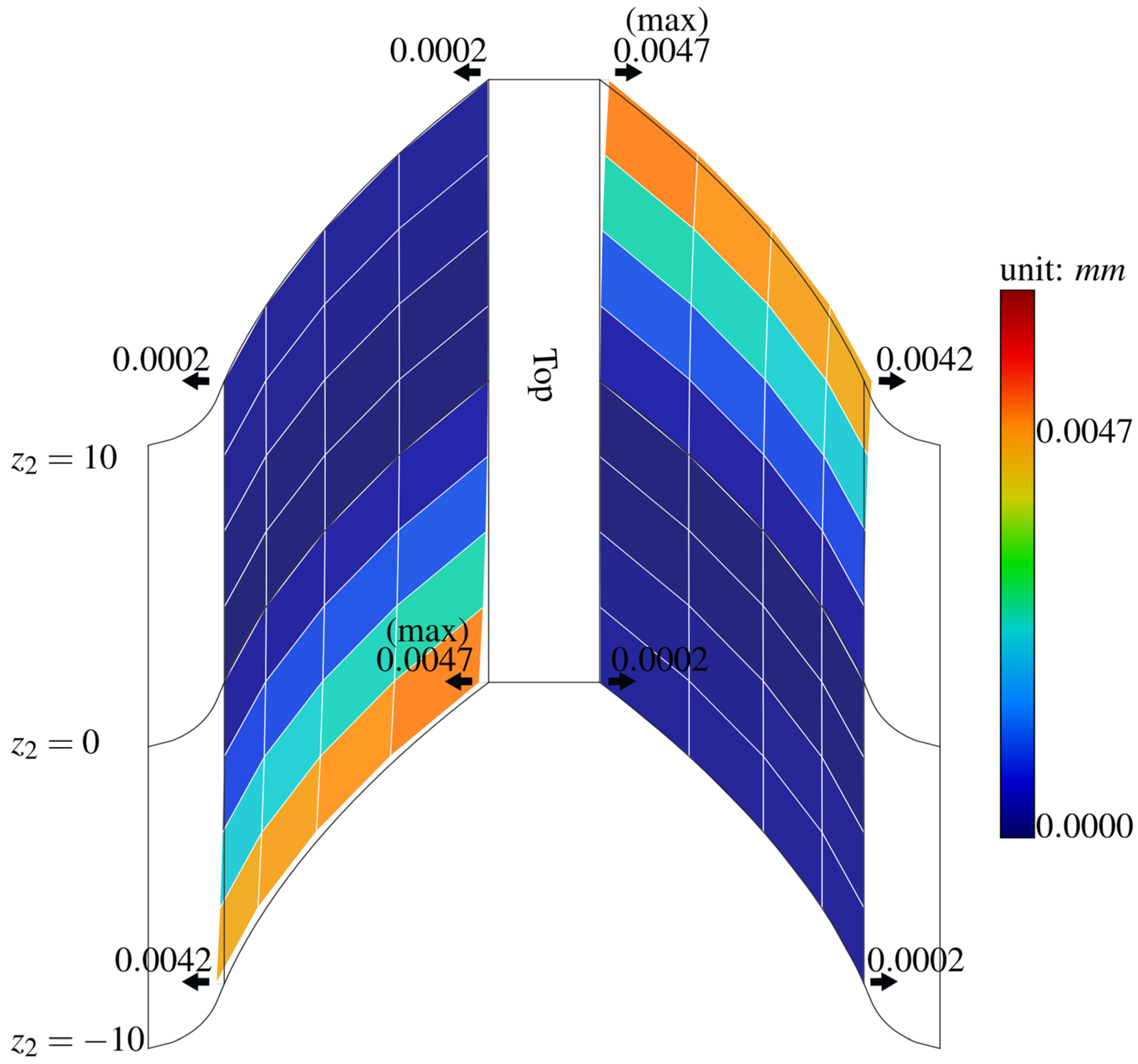
The resulting topographic error map of the shaved work gear is presented in
Figure 8. Compared with
Figure 7, reducing the worm helix angle yields a lower peak deviation and a more uniform error distribution across the active flank. Specifically, the maximum deviation decreases from approximately 5.5 µm (
Figure 7) to approximately 4.7 µm (
Figure 8). This improvement indicates that even a small adjustment of
can reshape the swept envelope (e.g., by changing the instantaneous contact-line orientation and surface curvature), thereby complementing the machine-setting compensation,
, for high-helix plunge-shaving cutters. The validity of this two-level optimization approach is firmly supported by the reliable convergence of the least-squares formulation after the underlying worm geometry (
) is altered. The final residual deviations are calculated based on strict conjugate kinematics rather than empirical approximations, ensuring the theoretical exactness of the evaluated topographic accuracy. The consistent reduction in peak deviation clearly confirms the numerical validity of the proposed compensation framework.
7. Discussion
The numerical results in
Section 6 indicate that generative grinding with an involute-helicoid worm, combined with center-distance compensation, provides a practical route for manufacturing plunge-shaving cutters with controlled topographic accuracy. Several aspects of the proposed framework warrant further discussion.
In Example 1, the single-parameter compensation through the parabolic coefficient, , reduces the maximum residual deviation on the shaved work-gear flank to approximately 2 µm, and the characteristic diagonal twist reported for cone-wheel finishing is substantially mitigated. This outcome suggests that, for moderate-helix configurations, the parabolic center-distance function, , offers sufficient control authority to reshape the worm-swept envelope and improve agreement with the theoretical cutter design. However, Example 2 reveals an important limitation: when the cutter helix angle increases to 20° with reversed helix direction, the maximum deviation rises to approximately 5.5 µm despite applying the same compensation procedure. This increase can be attributed to the growing geometric mismatch between the worm envelope and the target cutter surface at large helix angles, where the single degree of freedom provided by is insufficient to simultaneously reduce both the twist-like bias across the face width and localized peak deviations near the flank boundaries.
Example 3 explores an additional lever for improvement by adjusting the grinding-worm helix angle, . By reducing from 89.345° to 89°, the peak deviation decreases from 5.5 µm to 4.7 µm, and the deviation distribution becomes more uniform across the active flank. From a geometric standpoint, changing modifies the instantaneous contact-line orientation and the curvature characteristics of the swept envelope, which can redistribute the envelope-approximation error more evenly. It should be noted that, in the current study, was selected through a parametric comparison rather than a formal optimization loop. Incorporating into a multi-parameter optimization framework represents a natural extension of the present approach and may yield further improvement.
The benchmark comparison in Example 1 also suggests a potential advantage of worm-based generation under crossed-axis configurations. Due to its continuous generating action, a worm-shaped grinding tool may provide a smoother envelope evolution along the face width, which can reduce sensitivity to certain machine-setting mismatches. In contrast, cone-wheel finishing—although capable of achieving high accuracy under properly tuned conditions—can exhibit increased sensitivity to tool geometry and setting variations, which may manifest as twist-like topographic deviations. From this perspective, worm-based generation offers a stable baseline geometry upon which the -based compensation can act effectively.
Several practical factors not addressed in the current geometric–kinematic model may influence the achievable accuracy in industrial applications. Grinding-tool wear during generation can alter the effective worm profile over time, introducing deviations not captured by a static envelope model. Based on typical industrial conditions, such wear is expected to shift the effective involute profile gradually, which can be partially compensated by periodic re-identification of using the same least-squares procedure. Thermal expansion of the machine structure primarily affects the nominal center distance, , and its influence can in principle be mitigated through on-machine temperature monitoring and real-time center-distance correction. Elastic deformations may also shift the effective shaft angle from its nominal value. A quantitative assessment of these effects through coupled thermo-mechanical simulation and experimental measurement constitutes a major direction for future work. Furthermore, the present study evaluates topographic accuracy through numerical simulation only. Experimental validation—including coordinate measurement of ground cutter surfaces and flank inspection of shaved work gears—is required to confirm the predicted error levels and to assess the robustness of the compensation strategy under real-world disturbances.
8. Conclusions
This study presents a modeling and compensation framework for manufacturing plunge-shaving cutters using generative grinding with an involute-helicoid grinding worm. The main contributions and findings are summarized as follows:
A theoretical tooth-surface model of the plunge-shaving cutter, conjugate to a target involute helical work gear, was established based on crossed-axis envelope theory. This model provides a consistent reference geometry for evaluating the generated cutter topography.
A generative grinding model was developed in which the cutter surface is obtained as the envelope of a transformed worm surface family. A parabolic center-distance function, , was incorporated to enable longitudinal crowning and systematic error control through machine settings.
A practical compensation strategy was formulated by optimizing the parabolic coefficient, , using a linearized least-squares approach evaluated on a grid (45 points) on the operating pitch cylinder. In the benchmark moderate-helix case (Example 1), this single-parameter compensation reduces the maximum residual deviation on the shaved work-gear flank to approximately 2 µm while significantly suppressing the twist-like topographic bias associated with cone-wheel finishing.
For a more demanding large-helix configuration (Example 2), the maximum deviation increases to approximately 5.5 µm, indicating that single-parameter compensation alone is insufficient under challenging envelope conditions. By introducing a second-level optimization through adjustment of the grinding-worm helix angle (Example 3), the peak deviation is further reduced to approximately 4.7 µm—an improvement of about 15%—while producing a more uniform error distribution across the active flank.
Future work will incorporate additional process factors, such as grinding-tool wear and machine deformation, and will include experimental validation through coordinate measurements of ground cutter surfaces and flank inspections of shaved work gears.