1. Introduction
Cooperative control for MASs addresses a spectrum of fundamental problems, including consensus [
1,
2], tracking [
3], containment [
4], and formation control [
5,
6,
7]. MASs have garnered considerable research interest due to their wide applicability in various industrial domains [
8,
9]. However, as distributed control systems, MASs are inherently vulnerable to cyber–physical attacks in adversarial or high-interference environments. Such attacks have become a prevalent threat, capable of severely degrading the performance and compromising the security of distributed systems [
10,
11,
12,
13]. In response, resilient control has emerged as a critical paradigm to ensure the operational integrity of MASs under multiple attack scenarios. Resilient control strategies have been developed to counteract a wide range of threats, including actuator faults [
11], sensor faults [
10], false data injection (FDI) attacks [
14], denial-of-service (DoS) attacks [
15,
16], attacks involving malicious agents [
17], and hybrid attack vectors.
Adaptive control methods have been widely employed to address the resilient control problem in MASs, demonstrating significant effectiveness in this domain. Chen et al. [
11] addressed concurrent sensor and actuator faults in MASs by proposing a composite strategy integrating an adaptive compensation protocol with an
control design. For uncertain non-linear MASs under DoS attacks, Zhou and Tong [
18] achieved resilient formation control using a fuzzy adaptive control approach. Furthermore, Jiang et al. [
19] developed an adaptive observer-based control framework to solve the flexible output containment control problem for semi-Markov jump for fully heterogeneous MASs subject to DoS attacks. Model reference adaptive control (MRAC) is a well-established adaptive control methodology designed for systems with parametric uncertainties. In this framework, a reference model defines the desired closed-loop dynamics, and adaptive laws adjust the controller parameters to drive the plant output to track the reference model’s response to an external command [
20]. MRAC has proven effective for uncertain MASs, demonstrating success in scenarios such as consensus among leaderless heterogeneous agents [
21]. Then, Yue et al. [
22] formulated the leader-following problem by treating the leader agent as a reference model for the followers. Other works have leveraged MRAC’s ability to improve transient and steady-state performance to achieve consensus under various model uncertainties [
23,
24]. However, conventional adaptive control schemes exhibit certain limitations. Their performance is sensitive to the initial values of the adaptive parameters, and the design of the adaptation gain involves a fundamental trade-off between convergence rate and steady-state error. Furthermore, the aforementioned studies predominantly assume linear agent dynamics. This simplification, coupled with the common practice of not incorporating the leader’s dynamic information in leader-following consensus formulations, can lead to significant steady-state errors, or even consensus failure, in practical MASs. To solve this problem, we need to introduce other robust control methods on the basis of handling heterogeneous MASs through MRAC. Sliding mode control (SMC) is a prominent robust control technique, which is well-suited to handle system uncertainties and non-linearities. Its primary drawback, however, is the control chattering phenomenon. As analyzed in [
25], chattering fundamentally stems from the discontinuous nature of the control law and the inevitable switching dynamics in the vicinity of the sliding surface, which also points to potential mitigation strategies. One common approach is to smooth the control discontinuity, for instance, by replacing the signum function with a continuous approximation [
26]. Alternatively, reducing the sliding mode gain can alleviate chattering [
27], albeit at the cost of increased reaching time to the sliding surface. Achieving an optimal trade-off between robustness and chattering suppression remains a pivotal research challenge in SMC. To the best of our knowledge, research combining MRAC and SMC in MASs remains limited. For instance, the decentralized controller proposed in [
28] for interconnected non-linear systems employs Takagi–Sugeno fuzzy systems within an MRAC-SMC framework. However, that work neither considers the effects of cyber–physical attacks nor provides a system-level analysis from a distributed systems perspective.
While MRAC performance declines when large discrepancies exist between the reference model and the actual system, and SMC may induce severe chattering when sliding gains are raised for complex faults, combining both methods can enhance system resilience. By employing MRAC to mitigate uncertainties and SMC to eliminate residual errors, MASs achieve significantly improved resilience. Motivated by these findings, this paper investigates resilient control for MASs under cyber–physical attacks and parametric uncertainties, and designs a novel control scheme integrating SMC and MRAC. The designed sliding surface incorporates both the cooperative error and the reference model tracking error, ensuring their simultaneous convergence via the SMC action. The adaptation laws are derived through Lyapunov stability analysis which synthesize information from the reference model states, the cooperative error, and the sliding surface variable. Furthermore, the cyber–physical attacks considered in this work—encompassing FDI attacks and actuator faults—are modeled as an additive disturbance superimposed on the nominal control input. This unified mathematical representation simplifies the subsequent control design and analysis. In contrast to the existing studies on MRAC plus SMC, the proposed control protocol ensures controlled performance for MASs under cyber–physical attacks. Furthermore, unlike existing resilient control strategies for MASs based on adaptive control, our approach does not require followers to have knowledge of the leader’s reference control input, which better reflects practical constraints. This article is organized as follows.
Section 2 gives the preliminaries and system description. The controller design process and stability analysis are given in
Section 3.
Section 4 presents the simulations.
Section 5 concludes this article.
Notation 1.
, and represent the set of real number, dimensional Euclidean space and the set of real matrices, respectively. represents the 2-norm of vector . ⊗ represents Kronecker product. represents the n-dimensional identify matrix. represents the signal function. represents the trace of a matrix. represents the matrix negative definiteness in the usual quadratic form sense.
4. Simulation and Analysis
In this section, to verify the effectiveness of the proposed control protocol, two numerical simulations are designed and conducted. The simulation platform utilizes MATLAB R2022a.
Example 1.
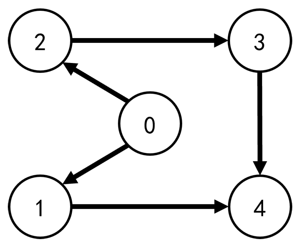
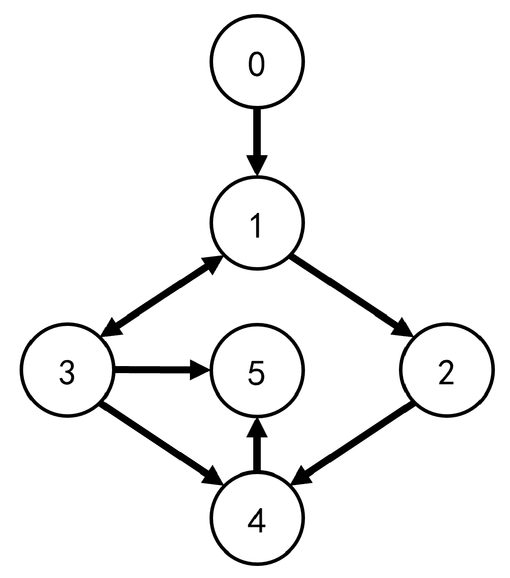
Consider the communication topology of heterogeneous MASs as Figure 1. The system considered in the simulation is a single-link robotic manipulator, following the dynamical model in [
35,
36]:
where the states
and
for
represent the joint angle and angular velocity, respectively. The parameter
is the total rotational inertia of the link and motor, and
is the damping coefficient. Furthermore,
,
g and
denote the link mass, gravitational acceleration, and distance from the joint axis to the link center of mass, respectively. The control input is denoted by
. The parameters are selected as
and
For
, we select that
and
, values that may account for variations due to wear and changes in electromagnetic characteristics. The initial state of manipulators is selected as
and
. The control input
for the leader is step input with an amplitude of 10 at
.
The control parameters are specified next to achieve leader-following consensus in the heterogeneous MASs. The naming conventions remain consistent with those defined earlier. For the reference model (
4), the following parameters are selected:
and
,
. For the sliding mode surface,
. For controller (
13),
and
.
To validate the selection of control parameters, a series of simulations was conducted, assessing
and
individually. In this simulation, the entire time span is 0 to
10 s, and the time step is given as 0.001 s.
Table 1,
Table 2,
Table 3,
Table 4 and
Table 5 illustrate the performance index of different parameters for the trajectory tracking error
based on mean squared error (MSE), which is given as MSE
. The parameter tuning was performed via a systematic sensitivity analysis, where each parameter was varied independently while holding all others constant.
The selection of
and
is provided in
Table 1 and
Table 2, respectively. The results indicate that the overall tracking error of the multi-agent system decreases as the adaptation
and
are reduced. However, when
and
, the benefit of further reducing
and
becomes negligible. The selection of
c is provided in
Table 3. It can be shown through
Table 3 that as the value of
c decreases, the MSE also decreases. However, similarly to the trend observed for
and
, a clear point of diminishing returns is reached for the coefficient
c when
. At same time, according to Theorem 2, the term
grows with increasing
, which means that for sufficiently large
, this term can dominate and violate the stability conditions derived in Theorem 2, potentially leading to a loss of consensus. The selection of
and
is provided in
Table 4 and
Table 5, respectively.
exhibits a trend similar to that of the previously discussed parameters. However, its admissible range is bounded by the stability conditions in Theorem 2, leading to the final selection
. For the sliding gain
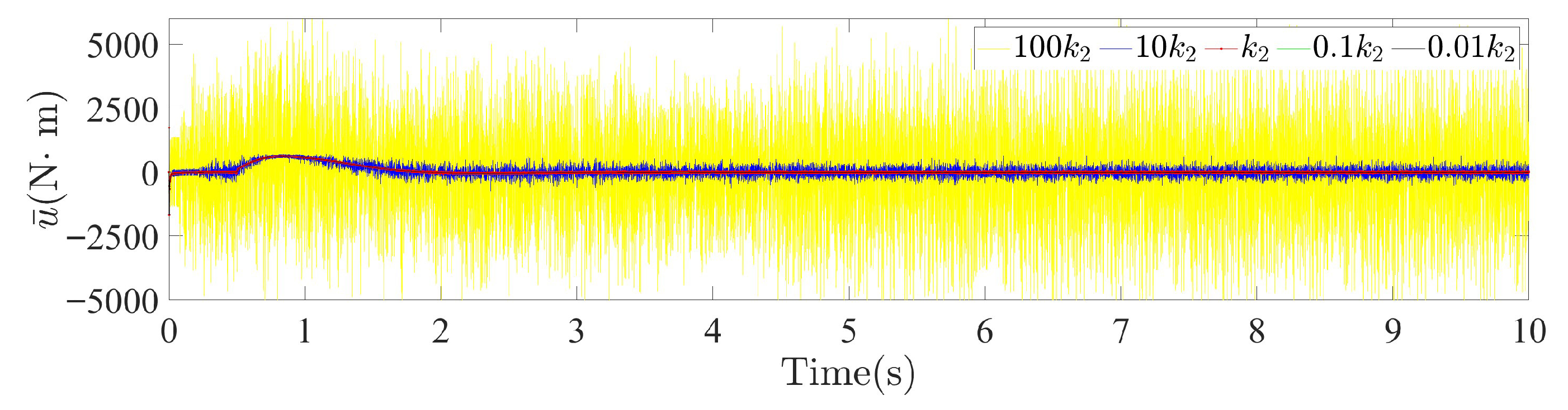
, while increasing its value reduces the tracking error, it also drastically amplifies control chattering. As shown in
Figure 2, increasing
from [40,3.2] to [4000,320] results in a 504.6-fold increase in the average chattering amplitude of the average control input
. This highlights a critical trade-off, necessitating a careful selection of
in practical applications with input constraints.
Then, we provided a comparison of different methods with the proposed MRASMC under attack conditions. In this simulation, the entire time span is 0 to
= 30 s, and time step is given as 0.001 s. The proposed MRASMC is compared with the traditional MRAC framework. The two are distinguished solely by the incorporation of the sliding mode component in MRASMC. Specifically, the traditional MRAC is obtained as a special case of the MRASMC by setting the sliding surface coefficient to
and the sliding gain to
. The proposed MRASMC is also compared with the SMC. The parameters of the SMC used for comparison are the same as proposed MRASMC. The sliding surface is designed as
, and the sliding mode controller is
. The comparative results demonstrate that integrating SMC into the MRAC framework significantly enhances its performance in achieving resilient consensus for MASs. As an additional benchmark, the vMRAC method from [
22] is included in the comparison. This method was specifically designed for achieving leader–follower consensus in heterogeneous MASs.
The actuator gain fault
in (
2) varies across agents that
,
,
,
and
. The signal
in (
2) is applied to the system during two intervals:
and
. Furthermore, the magnitude of the disturbance acting on each agent varies over time. Specifically, the fault signals for each agent are defined in
Table 6:
Table 6.
Fault list of agents.
Table 6.
Fault list of agents.
| Agent | Bias Fault 1, | Bias Fault 2, |
|---|
| agent 1 | 37.5 + 7.5 − 3.75 | 75 + 37.5 − 3.75 |
| agent 2 | 37.5 | 75 |
| agent 3 | 0 | 0 |
| agent 4 | if , 37; else 0 | if , −37.5; else 0 |
| agent 5 | | |
where % denotes the modulo operator. It should be mentioned that the periodic square-wave fault applied to Agent 4 in
Table 6 is generated by performing a modulo operation on the time variable
t. Specifically, during the time interval
, the FDI signal
is described as if
, then
; otherwise,
. This means that the square wave has a period of 6, with the high-level signal lasting for three time units and the low-level signal lasting for three time units. Correspondingly, during the time interval
, the FDI signal
is described as if
, then
; otherwise,
. This means that the square wave has a period of 17, with the high-level signal lasting for 5 time units and the low-level signal lasting for 12 time units. The above design can be uniformly expressed as
The
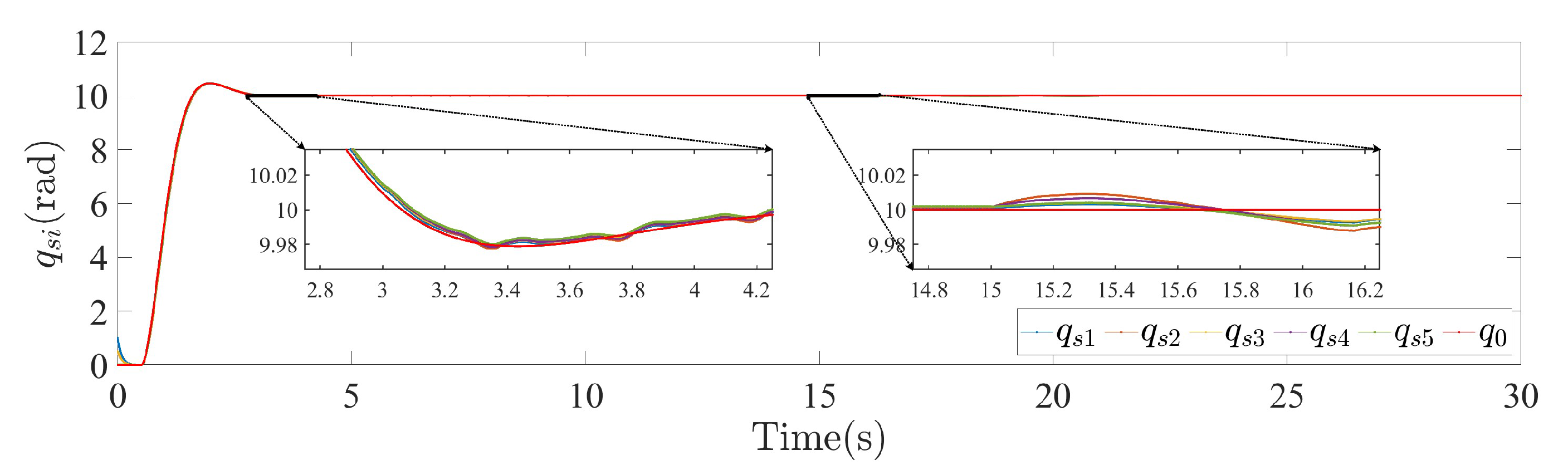
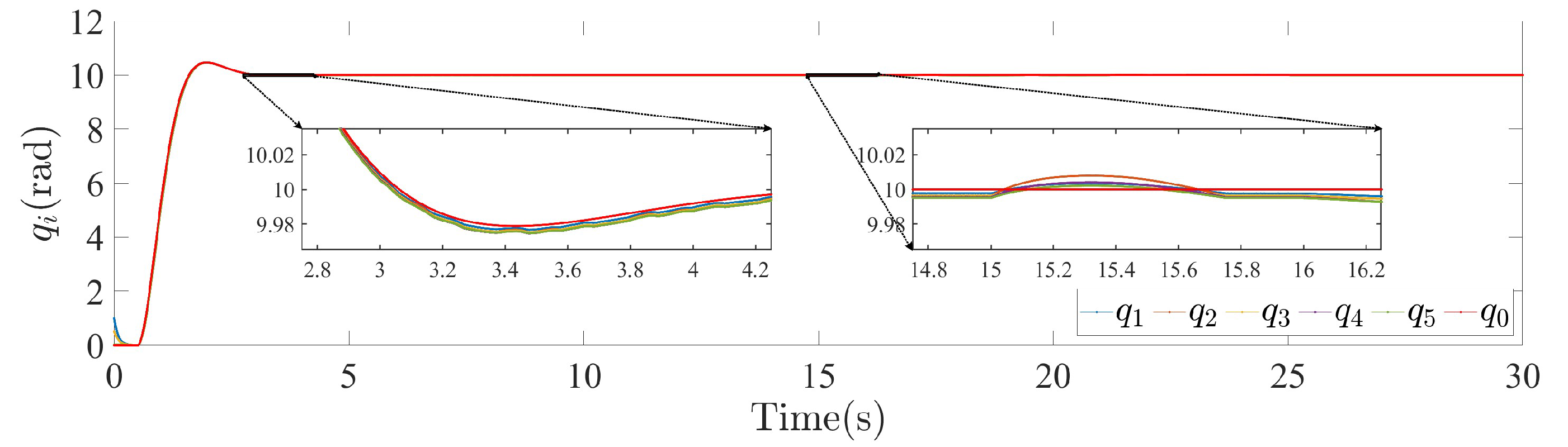
Figure 3 shows the trajectories of MASs under MRASMC. The
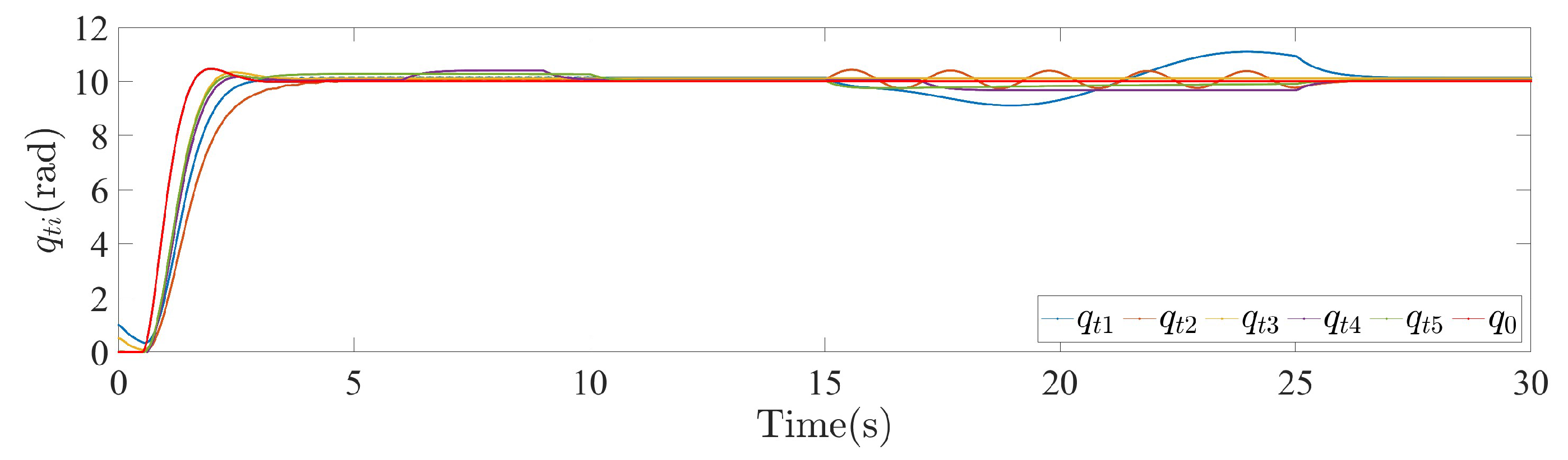
Figure 4 shows the trajectories of MASs under MRAC. The
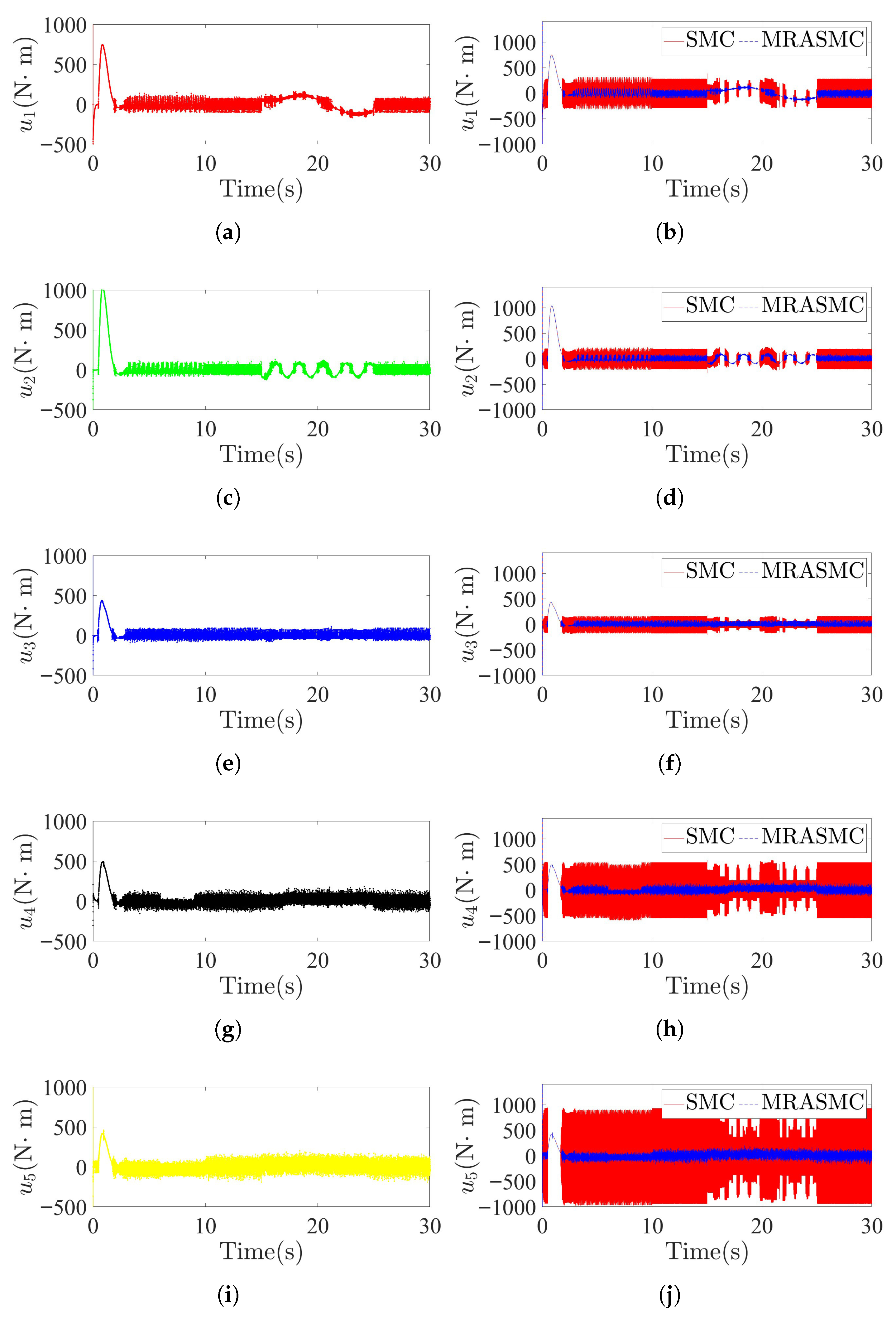
Figure 5 shows the trajectories of MASs under SMC. The control input is shown in
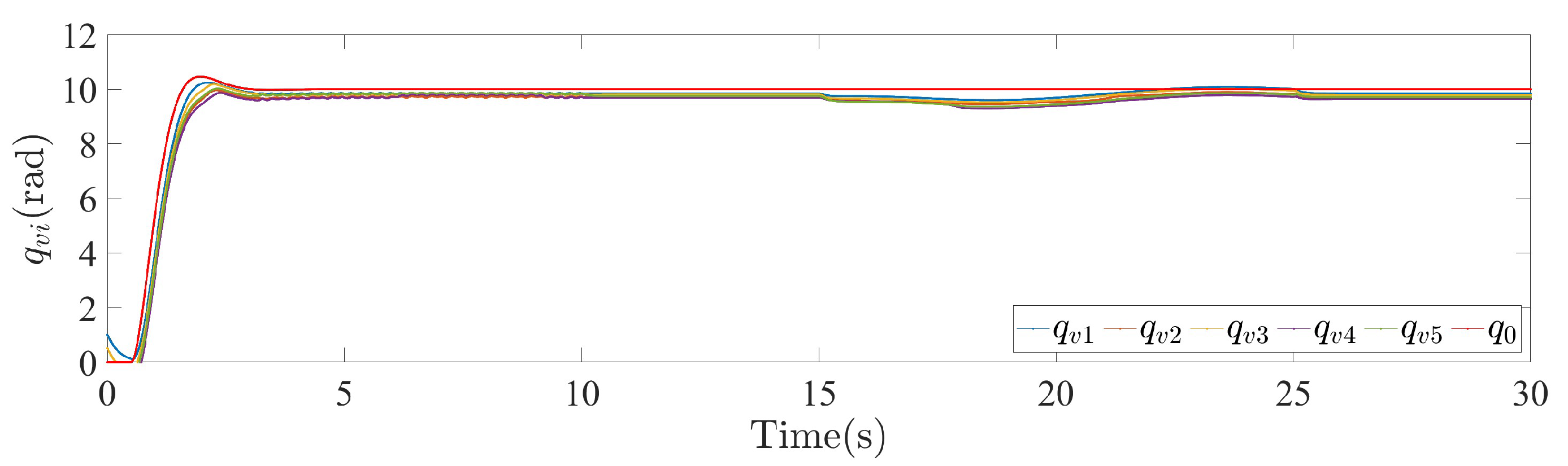
Figure 6. The trajectories of MASs under vMRAC is shown in
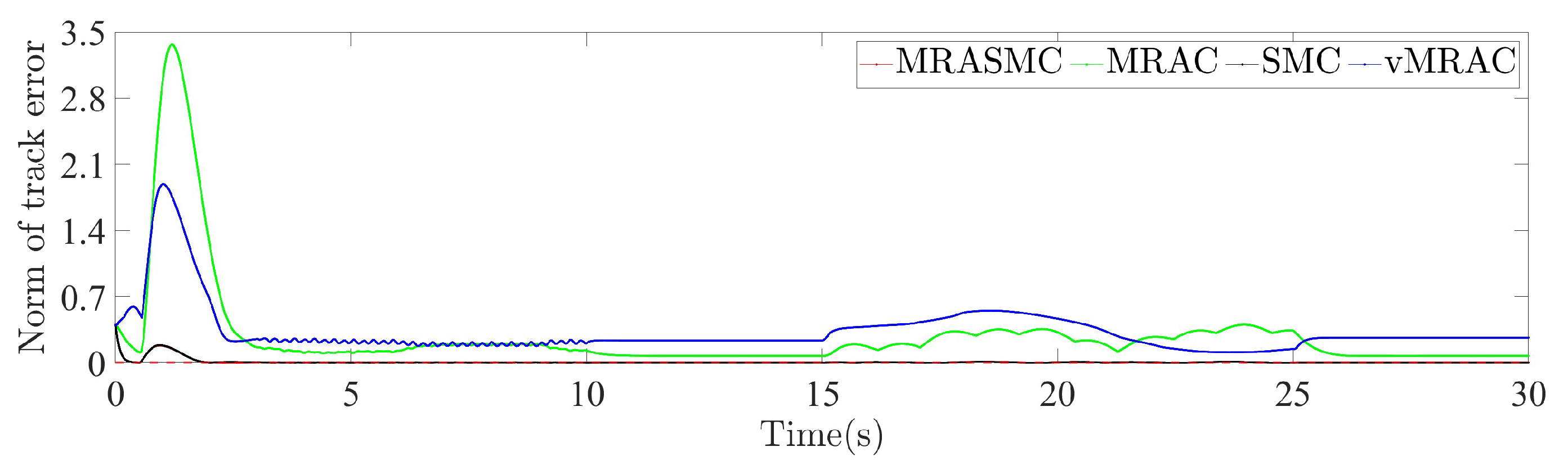
Figure 7. The norm of tracking errors is shown in
Figure 8.
Table 7 illustrates the performance index of different methods for tracking error based on MSE. Specifically, the performance comparison reveals distinct behaviors among the three methods under fault versus non-fault conditions.
Table 7 demonstrates that the proposed MRASMC achieves significantly superior control performance compared to the other methods.
By explicitly accounting for the uncertainties inherent in heterogeneous MASs and the effects of unknown faults, the proposed MRASMC achieves superior performance across all simulated environments.
In contrast to the proposed MRASMC, the traditional MRAC lacks the sliding mode control component. Consequently, in the absence of faults, the tracking errors for both methods are comparable, as evidenced by the results in
Figure 8. However,
Figure 4 reveals that traditional MRAC, due to its lack of explicit fault suppression capability, experiences more significant performance degradation in the presence of actuator faults compared to the other methods.
Table 7 and
Figure 5 demonstrate that the sliding mode component effectively suppresses faults and reduces tracking errors, contributing to the superior performance of MRASMC over the compared MRAC-based methods. However, the SMC law with the designed control parameters induces severe chattering in the control input, as shown in
Figure 6.
Figure 6 shows that the control inputs of different agents. Specifically,
Figure 6a,c,e,g,i present the control signals generated by the proposed MRASMC method for each agent. The control input exhibits a clear compensatory response when the actuator fault is active, directly countering its effect. This behavior validates the designed control protocol’s inherent fault-tolerance mechanism. Furthermore, it is observed that the chattering in the control input is more severe for certain agents, such as agent 4 and 5. This phenomenon can be attributed to the propagation and accumulation of tracking errors along the network topology, a process exacerbated in the presence of faults or attacks. At the individual agent level, this manifests as a more complex composite fault signal. To counteract such aggravated disturbances, it is manifested at the control input as more intense chattering in sliding mode control.
Figure 6b,d,f,h,j provide a direct comparison, comparing the control inputs from the SMC method against those from the MRASMC method for each agent. The results demonstrate a reduction in control input chattering for MRASMC compared to SMC, especially during the periods from 4 to 12 and from 25 to 30. Theoretically, this improvement stems from the MRAC component’s compensation for terms
. This theoretical analysis is directly validated by the simulation setup, where the only difference between the compared SMC and the MRASMC is the presence of the adaptive part. Consequently, the simulations confirm that the adaptive control component within the MRASMC framework is responsible for the effective suppression of sliding-mode-induced chattering.
The vMRAC method treats the leader agent directly as the reference model for all followers, which enables consensus under its control framework. However, this approach relies on several simplifying assumptions that leader agent features a linear, disturbance-free dynamics with a known reference input. Consequently, compared to the proposed MRASMC, vMRAC exhibits higher sensitivity to the modeling inaccuracies of the leader, leading to greater performance degradation in consensus under realistic perturbed conditions.
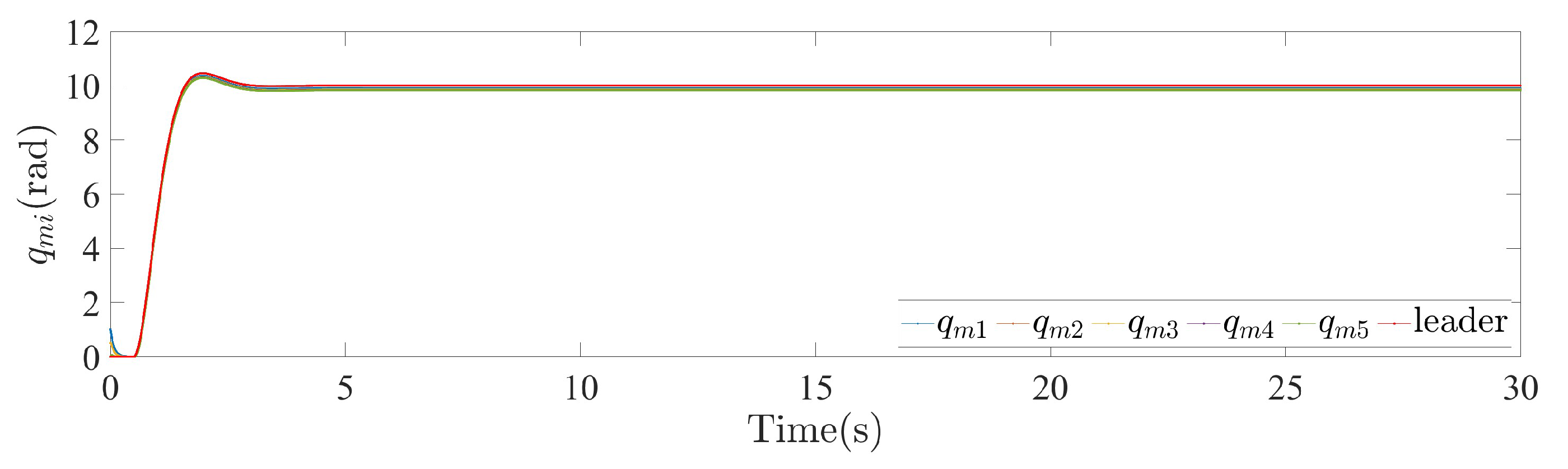
Furthermore, in addition to the tracking error discussed previously, the following elements of the MRASMC scheme are also examined: the reference model in
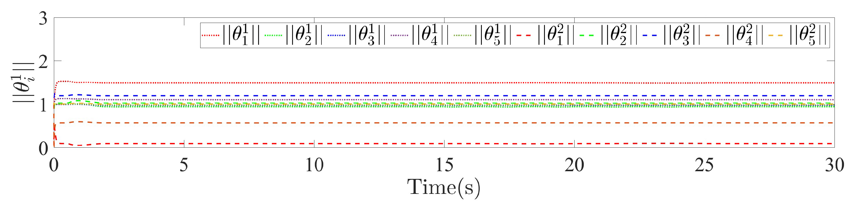
Figure 9, adaptive parameters in
Figure 10, control inputs in
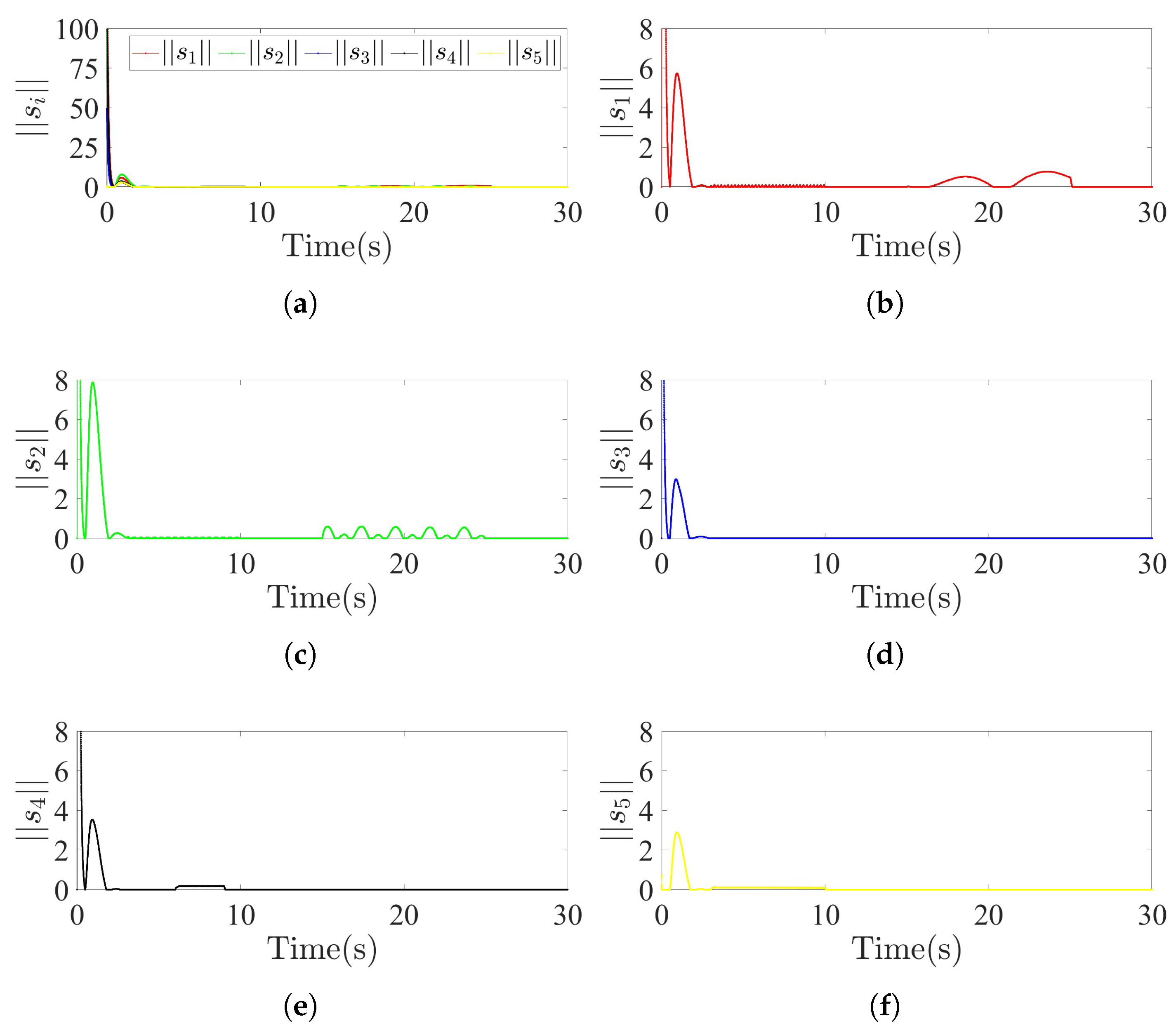
Figure 6, and sliding mode surface in
Figure 11.
Figure 9 illustrates the reference models achieve consensus through the cooperative controller
. At the same time, it cannot be ignored that the steady-state error caused by the leader predicted in Theorem 1 is also reflected in the figure.
Figure 10 shows that the adaptive parameters designed by (
13) and (
17) converge quickly into place.
Figure 11 illustrates the convergence of the sliding surface. Upon activation of the controller, MRASMC drives each agent rapidly from its initial state toward the leader’s initial state. During the ensuing process, the agents occasionally exhibit deviations from the sliding surface. This behavior is inherent to the sliding surface design, which incorporates both the cooperative error and the reference model tracking error. The case of Agent 3 illustrates this mechanism. Since Agent 3 is not subjected to any external attack in the simulation, its state remains on the sliding surface for most of process. The only observed deviation occurs at t = 0.5 s, which is triggered solely by the change in the leader’s state.
Example 2.
To verify the universality of the advantages of MRASMC, we conducted simulations on a multi-flexible single-link manipulator systems. In this simulation, the entire time span is 0 to 50 s, and time step is given as 0.0005 s. Consider the communication topology of heterogeneous MASs in Figure 12. The system considered in the simulation is a single-link flexible manipulator, following the dynamical model in [
37,
38]:
where
,
, and
for
represent the motor rotor rotation angles, motor rotor angular velocity, link rotation angles, and link angular velocity, respectively. The system parameter
and
represent the motor rotor inertia, link inertia, joint elastic constant, viscous friction, mass, gravitational acceleration, and length, respectively. The control input is denoted by
. The parameters are selected as
and
. For
, we select that
and
. For
, we select that
and
. The initial state of manipulators is selected as
and
. The control input
for the leader is
. The naming conventions of the controller remain consistent with those defined earlier. For the reference model, the following parameters are selected as
and
,
. For the sliding mode surface,
. For the controller,
and
. For the comparison control protocols, the method for selecting the controller parameters is similar to that in Example 1. The actuator fault and FDI attack are defined in
Table 8 and
Table 9.
The periodic square-wave actuator gain fault applied to Agent 3 in
Table 8 is defined in
Table 6,
represents the uniform random noise with mean of 0 and variance of 0.1, and
represents the uniform random noise with mean of 0 and variance of 0.25.
The periodic square-wave FDI attack applied to Agent 4 in
Table 9 is defined in
Table 6. Similarly, we present
Table 10 as the control results of different methods in the case of Example 2.
Table 10 illustrates that the proposed control method still maintains its advantages over other control methods under different topologies, which indicates the robustness of the proposed method to communication topologies and different control gains.
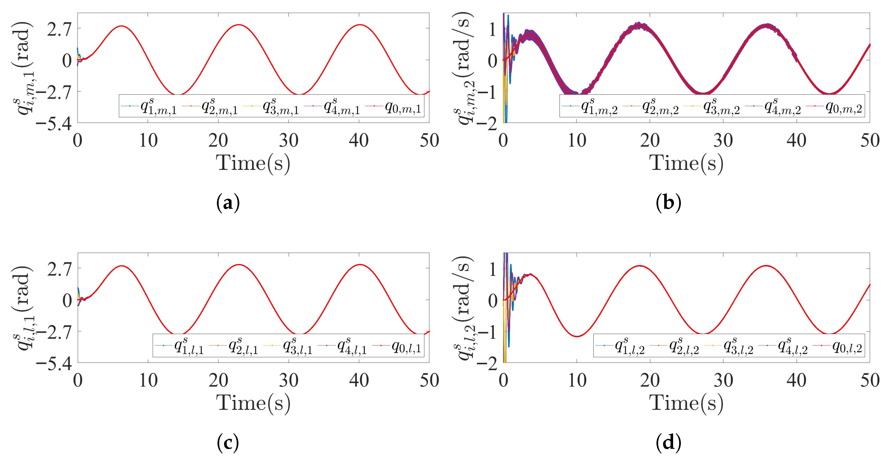
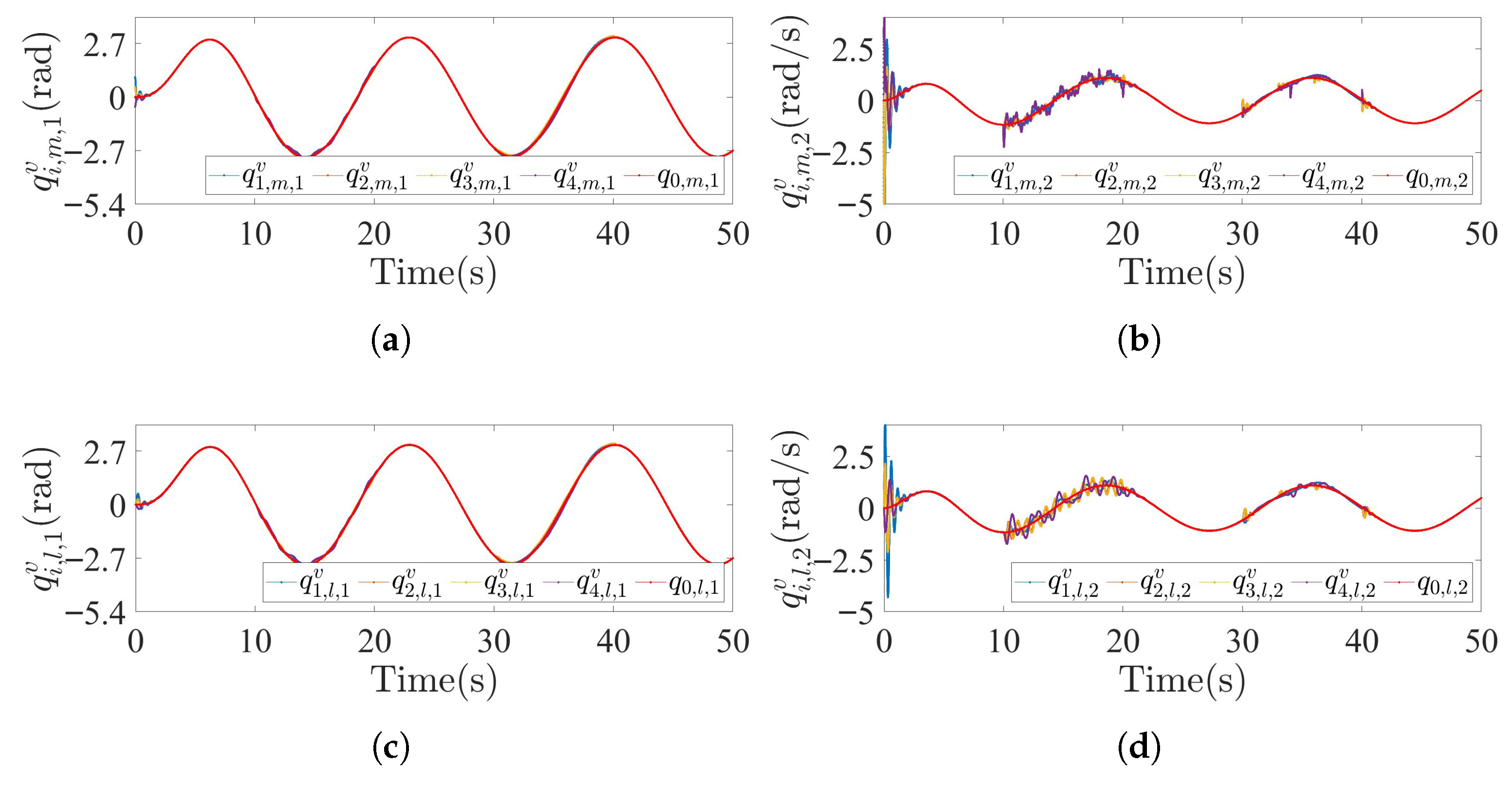
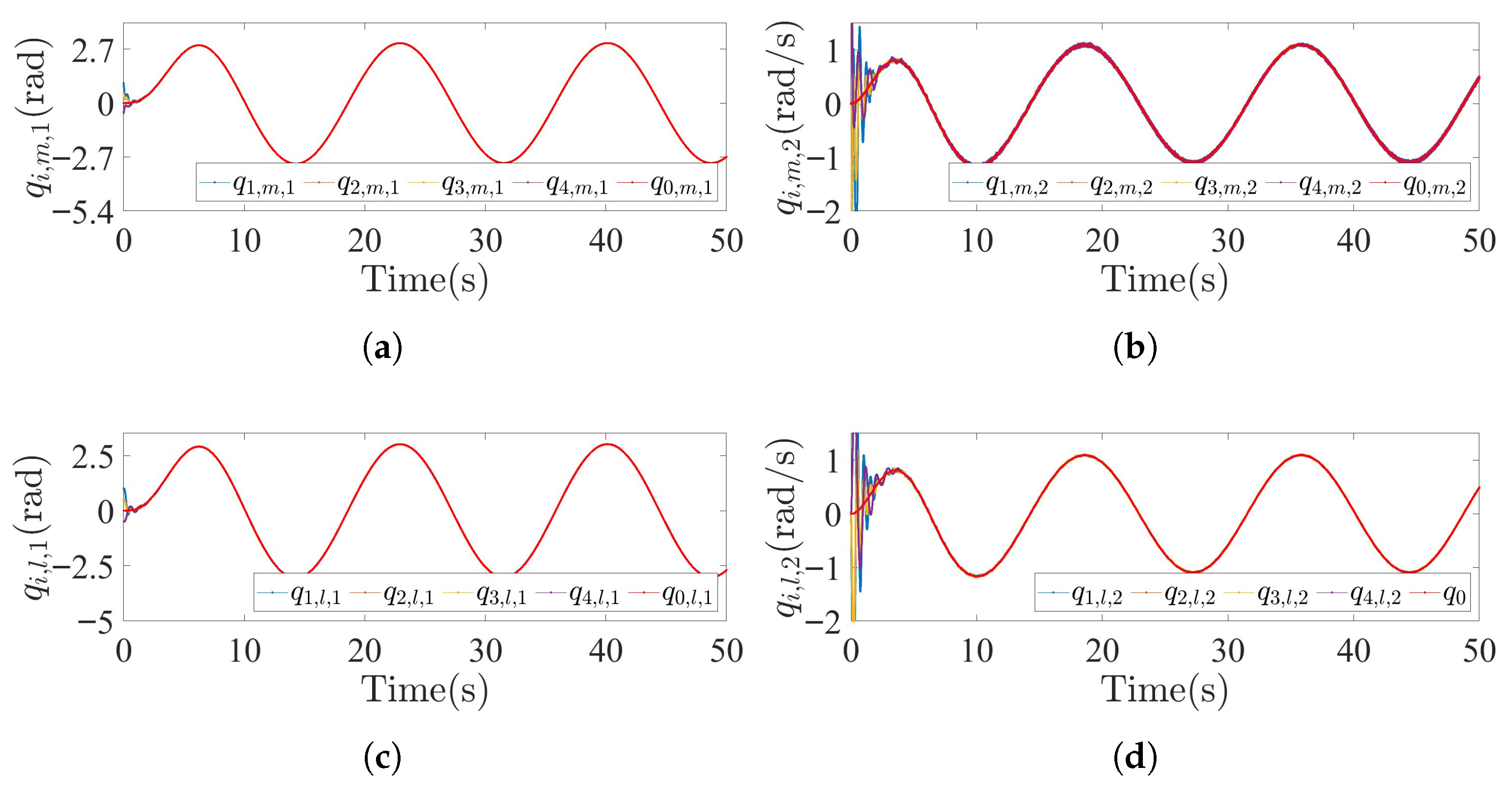
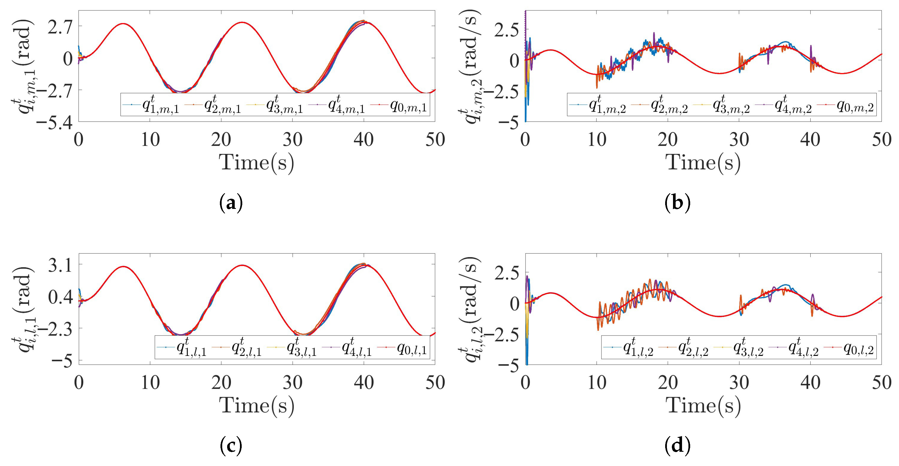
Figure 13,
Figure 14 and
Figure 15 illustrate the trajectories of multi-flexible manipulator systems under MRASMC, MRAC, SMC, respectively.
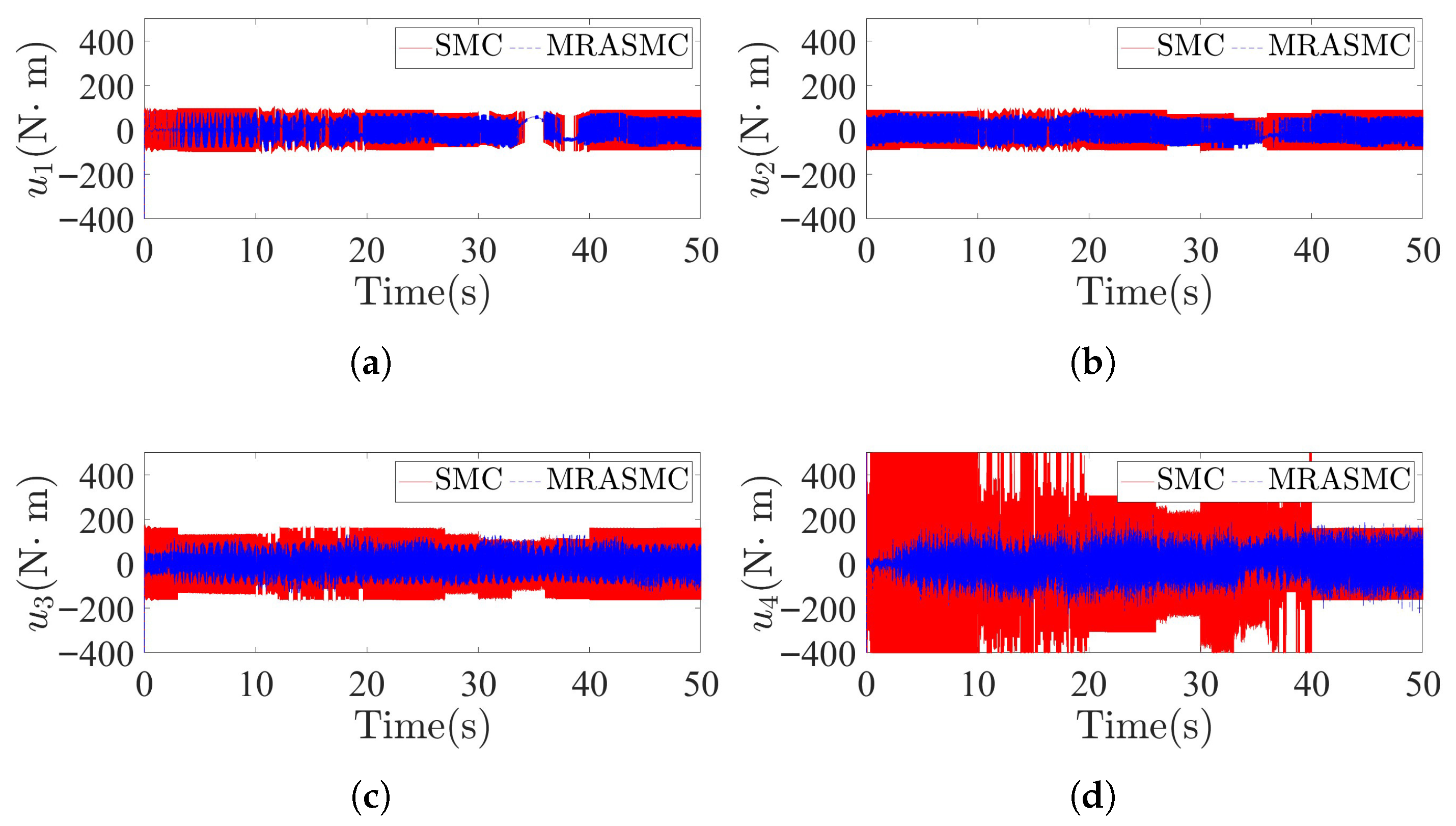
Figure 16 represents the control inputs of multi-flexible manipulator systems under MRASMC and SMC, and
Figure 17 illustrate the trajectories of multi-flexible manipulator systems under vMRAC.
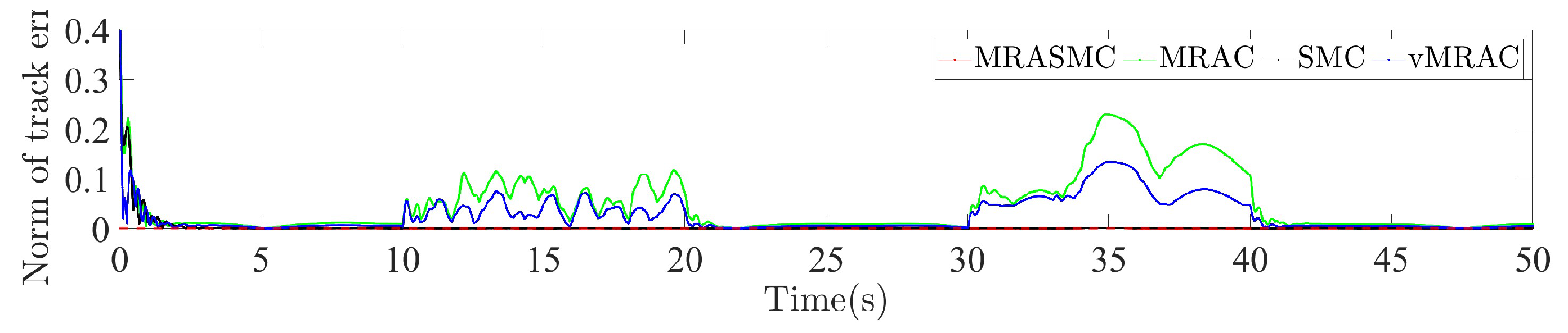
Figure 18 shows the norm of tracking errors of multi-flexible manipulator systems under different control methods. The simulation results from Example 2 further validate the efficacy of the MRASMC framework. As shown in
Figure 14 and
Figure 17, MRASMC delivers superior robustness and lower tracking error compared to both the baseline MRAC and the vMRAC methods, owing to its integrated sliding mode control module. Concurrently, by leveraging its adaptive control component, MRASMC effectively mitigates the chattering in the control signal, representing an improvement over conventional SMC, as evidenced in
Figure 16.
In general, through the above simulation analysis, it can be determined that the proposed MRASMC strategy can achieve the desired control objectives.