1. Introduction
Bearings are crucial components of mechanical systems and have been widely used in various fields such as agricultural machinery, transportation, aerospace, and others [
1]. In industrial production, over 30% of equipment faults are caused by bearing faults, making them the most common type of fault [
2]. Generally, bearings fail mainly due to fatigue, wear, improper installation, and other factors, leading to equipment shutdown, production interruption, and even safety accidents [
3,
4]. Therefore, fault diagnosis and diagnosis in bearings are essential to identify anomalies, reduce downtime, and prevent unexpected failures [
5].
Signal processing-based methods focus on in-depth analysis and the processing of bearing operation data to extract fault feature information [
6]. Common signal processing methods include Empirical Mode Decomposition (EMD) [
7], Ensemble Empirical Mode Decomposition (EEMD) [
8], Wavelet Transform (WT) [
9], Variational Mode Decomposition (VMD) [
10], etc. Liu et al. [
11] combined time–frequency maps of original time-series signals with pretrained models, significantly improving the accuracy of fault diagnosis and reducing the model training time; Jiang et al. [
12] utilized convolutional capsule networks to transform wavelet time–frequency graph features into vector neurons, and the dynamic routing algorithm is used to achieve feature transfer and output the results of fault diagnosis; Ning [
13] adopted the Markov frequency-domain image transformation method to convert discrete signals into probabilistic models, using 2D frequency-domain images as inputs to complete time-series classification. Chen et al. [
14] used Fast Fourier Transform (FFT) to convert raw data from the time domain to the frequency domain, obtaining high-dimensional feature data and verifying its effectiveness in the fault detection of mechanical transmission systems. In general, fault diagnosis methods based on signal processing usually have strict requirements on data dimensions, thus limiting the scalability of feature dimensions. These studies show that signal processing-based methods can effectively extract fault features in specific scenarios, but their diagnostic performance is easily affected by changes in working conditions, and their robustness and adaptability are insufficient under complex working conditions.
Data-driven methods use machine learning [
15] and deep learning [
16] technologies to mine potential fault patterns from bearing operation data, significantly improving the intelligence level of fault diagnosis. Bao et al. [
17] combined channel dictionaries and convolutional dictionaries to achieve an accurate detection of weak faults in bearings. Xu et al. [
18] constructed an FFT–CNN–Transformer network model to realize the automatic fault diagnosis of rolling bearings by combining frequency-domain features with deep learning networks. Yan et al. [
19] proposed a bearing fault diagnosis method combining a 1D Convolutional Neural Network (1D-CNN) and Kolmogorov–Arnold Network (KAN), replacing the fully connected layer of a traditional CNN with a KAN layer and using its strong nonlinear processing and function approximation capabilities to further improve diagnostic performance. Jing and Zhao [
20] proposed an FFT-driven Transformer (FGF-Trans) framework, which combines a frequency global filter block with the Transformer module, enabling it to capture the global contextual information of all features and better extract fault feature information in noisy environments. However, data-driven methods usually rely on large-scale fault samples for training procedure and lack model interpretability, which limits the model generalization ability under complex working conditions.
Multi-source information fusion methods integrate multiple data sources such as vibration signals [
21], temperature signals [
22], and acoustic signals [
23,
24] to make full use of the complementarity between different signals, providing a new technical direction for bearing fault diagnosis. Liu et al. [
25] used Gram matrices to convert 1D data into 2D feature representations and combined Bidirectional Long Short-Term Memory (BiLSTM) and 2D Convolutional Neural Networks (2D-CNN) to realize the classification of rolling bearing faults. Tian et al. [
26] proposed a diagnosis method based on time-domain, frequency-domain, and time–frequency-domain information entropy features, identifying different fault states through multi-domain information entropy matrix distance analysis. Zhang et al. [
27] used Continuous Wavelet Transform (CWT) and Short-Time Fourier Transform (STFT) to convert 1D vibration signals into 2D time–frequency maps, combined Depthwise Separable Convolution (DSConv) and Convolutional Block Attention Module (CBAM) to enhance fault feature extraction capability, and introduced an optimized dilated residual convolution module to significantly improve the generalization ability of the model. Wang [
28] used a Transformer model to comprehensively consider the relationships between electrical parameters, oil temperature, and other factors in different time periods with its self-attention mechanism capturing long-distance dependencies. Wang et al. [
29] designed a multi-level information fusion strategy combining feature layers and decision layers, further improving diagnostic efficiency by solving the redundancy and noise problems between multi-source data. Choudhary et al. [
30] used a CNN model to realize the fault identification of asynchronous motors by using the fused features of acoustic signals and vibration signals of asynchronous motors.
Although the above methods have achieved significant progress in the field of bearing fault diagnosis, there are still the following problems: (1) signal processing-based methods have poor robustness and are difficult to fully characterize bearing fault features; (2) data-driven methods lack physical interpretability, making it difficult to obtain complete data parameters of bearing experiments, and the model is easily affected by sample quality and changes in working conditions; (3) most multi-source information fusion methods only focus on the data-level fusion, failing to effectively integrate the physical mechanism of bearing operation with learning models; and (4) in the collection of experimental data, the lack of bearing physical parameters or other key data will affect the physical interpretability of the model.
Given the key role of bearings in mechanical equipment and the importance of their fault diagnosis for preventive maintenance, current methods often suffer from a significant decline in the interpretability of diagnostic models due to the lack of bearing physical parameters (such as the outer diameter of the bearing, the inner diameter of the bearing, the number of rolling bodies, etc.), affecting the reliability of practical applications. However, in recent years, emerging technologies represented by large language models have opened up new paths for adaptive fault diagnosis. The generalization ability of models is enhanced through knowledge injection [
31]. This research demonstrates the emerging direction of using large language models for adaptive diagnosis/knowledge injection. In light of the above-mentioned issues, this paper draws on the strengths of these studies while addressing their weaknesses and proposes multi-source information fusion with physical prior knowledge [
32]. This method integrates multi-source information such as sensor data and vibration signals, and it embeds physical prior knowledge to enhance the interpretability and robustness of the diagnostic process, effectively reducing performance fluctuations caused by the lack of physical parameters. The main innovations of this paper are as follows: (1) proposing a multi-source information collaborative diagnosis framework integrating physical prior knowledge, which adopts a hierarchical structure to integrate data features and physical constraints, realizing end-to-end information complementarity and collaborative analysis; (2) designing a loss function based on physical laws, which combines the bearing motion laws and energy conservation principle as a regularization term to guide model training, optimize the parameter updating process, and improve generalization ability; (3) verifying the effectiveness and advantages of the proposed method under complex working conditions through multi-dataset experiments.
The remaining part of this paper is structured as follows:
Section 2 outlines the theories and model framework used in this paper;
Section 3 introduces the experimental datasets, experimental settings, and analysis of experimental results;
Section 4 summarizes the main conclusions of this paper.
2. Research Methods
2.1. Transformer Model
The Transformer model is a deep learning model architecture based on the attention mechanism [
33], which is essentially a stacked encoder–decoder structure composed of several stacked encoders and decoders [
34]. Since its advent, the Transformer model has attracted wide attention in the field of Natural Language Processing (NLP) and quickly become the main method for processing sequence data. Transformers can effectively handle long-distance dependencies and have strong parallel computing capabilities, greatly improving training efficiency.
Encoders and decoders are fundamental components of Transformer models. Encoders extract and encode information from the input data, capturing relationships between elements. Conversely, decoders generate target sequences based on the outputs of the encoder, effectively converting the context information into an output sequence.
The multi-head attention mechanism in Transformer models serves to extract information and represent features [
35]. It maps the input signal to three different vector spaces through three independent linear transformations to obtain queries (
Q), keys (
K), and values (
V). For each head
h, its calculation process is as follows:
Among them, , and are the weight matrices of Q, K, and V respectively.
The attention scores are normalized by the softmax function to obtain the attention weights:
The scaling operation is designed to prevent the dot product result from being too large, which may lead to gradient vanishing or explosion.
As shown in
Figure 1, the output is calculated based on the attention weights:
Finally, the outputs of each head are concatenated:
Then, the concatenated output is projected back to the d-dimensional space through a fully connected layer:
Among them, is a learnable parameter matrix.
2.2. Vision Transformer Model
Vision Transformer (ViT) is a computer vision model based on the Transformer architecture [
36], consisting of image partitioning, patch embedding, positional embedding, a Transformer encoder, and a fully connected layer [
37]. The core idea of this model is to divide the input image into several image patches, flatten them, and rearrange them into serialized data. These serialized data are then linearly mapped to a high-dimensional embedding space and integrated with positional encoding information. The processed embedding sequence is used as the input of the Transformer encoder, and the global dependencies between different image patches are modeled through the self-attention mechanism, thereby realizing effective characterization of the overall contextual information of the image.
First, the input image
X is divided into multiple
P ×
P patches. The number of patches is
Among them, H and W are the height and width of the image, respectively.
Each patch is flattened and mapped to a fixed high-dimensional embedding space through a linear layer before being input into the model. Let the embedding dimension of the patch be
D; then, the embedding of each patch can be expressed as
Among them, is the i-th patch of the input image ; is the linear mapping of ; is the embedding weight matrix; and is the bias term.
After adding positional encoding to all patches, the embeddings are merged into the input matrix of the Transformer:
The formula calculation of ViT involves multiple parts such as image patching, embedding, positional encoding, a self-attention mechanism, a feedforward network, and layer normalization. Through these calculations, ViT can effectively process image data and achieve excellent performance in computer vision tasks.
2.3. Information Fusion Module
Vibration signals of bearings under different working conditions can be collected by sensors, but it is difficult to obtain the fault category directly using vibration signals. The vibration signal can be converted into a state-related frequency spectrum through FFT, from which frequency domain information can be obtained. In addition, the vibration signal can be converted into a state-related time–frequency map through STFT, which can intuitively show the dynamic changes of frequency components in the signal, thus providing important information for fault diagnosis. The working conditions of bearings are the focus that operators must pay attention to at all times, and relevant information needs to be recorded in a timely manner. Compared with vibration signals, these text records are also important for judging the bearing state. Each type of the above information can play a role in bearing fault diagnosis. Adhering to the concept of “1 + 1 > 2”, three types of information are fused to complement each other and provide a more reliable basis for fault diagnosis.
FFT and STFT have their unique advantages in signal processing at the 1D and 2D levels, respectively, and they can extract features using the multi-head attention mechanism through Transformer and ViT, respectively. The text information on working conditions extracts key features through regularization technology, which is used as the Query (
Q) in the multi-head attention calculation, while the FFT features Key (
K) and Value (
V) are used for calculation, and the STFT features
K and
V are also used for calculation. Physical information reflects the physical background and operating state of the signal. Through the cross-attention mechanism, physical information can selectively extract information related to itself from FFT and STFT features, improving the model performance. The relevant calculation of cross-attention is as follows:
Among them, is the physical information feature extracted from the working condition text, are the key vectors corresponding to FFT features or STFT features, are the value vectors corresponding to FFT features or STFT features, and and are the attention outputs for FFT features and STFT features, respectively.
2.4. Physical Embedding Module
In relevant studies on bearing faults, experiments with variable loads and variable speeds are often involved, and a large number of variable load and variable speed experiments are conducted to analyze bearing health states. However, fault mode recognition is only realized through the strong feature extraction capability of deep learning without considering the actual physical meaning of load and speed.
The influence of load on bearing faults is mainly reflected in the energy of vibration signals. The magnitude of the load directly affects the contact force between the rolling elements and the raceway inside the bearing. When the load increases, the interaction force between the rolling elements and the raceway strengthens, causing the fault area to bear a greater impact force, thereby increasing the amplitude of the vibration signal and making the energy of the fault characteristic frequency more significant.
The influence of speed on bearing faults is mainly reflected in the spectral peaks. When the speed increases, the fault characteristic frequency also increases, and the characteristic frequency components in the vibration signal become higher, which are more easily captured by frequency-domain analysis methods. At high speeds, sliding friction and the dynamic effect of the lubricating oil film may introduce more nonlinear features, making the vibration signal more complex. Common phenomena include harmonic frequency, sub-harmonic frequency, and frequency mixing components. Therefore, changes in speed will lead to fluctuations in spectral peaks.
This paper realizes bearing fault diagnosis by constructing a loss function with physical significance. The loss function mainly includes four types of losses: cross-entropy loss, physical constraint loss, frequency consistency loss, and load consistency loss.
The cross-entropy loss predicts the compatibility between the bearing fault mode and the real label [
38], and its calculation is as follows:
Among them, is the one-hot encoding of the real category label, is the prediction probability of the model for category i, and N is the number of samples.
The physical constraint loss is calculated as follows:
Among them, is the FFT global feature obtained by Transformer, is the STFT global feature obtained by ViT. is the feature extracted from FFT and STFT features through attention calculation with physical information features as Q, and is the mean square error used to measure the difference between the two. Physical working conditions (such as rotational speed and load) can change the explicit manifestations of fault features (such as amplitude and frequency).
The frequency consistency loss is calculated as follows:
Among them,
is the spectral peak in the
feature,
is the normalized spectral peak, and
is the normalized rotational frequency. This loss term is directly related to the kinematic principle of the bearing. There is a definite linear relationship between the fault characteristic frequency of the bearing and the rotational frequency of the shaft.
Among them, is the average energy in the feature, is the normalized average energy, and is the normalized load. This loss term encodes the principle of the dynamic response of the bearing. The load has a direct and significant impact on the energy of the vibration signal of the bearing fault.
The total loss is calculated as follows:
Among them, , and are the weight coefficients of each loss, respectively.
2.5. Model Architecture of Physics Prior Knowledge Deep Learning
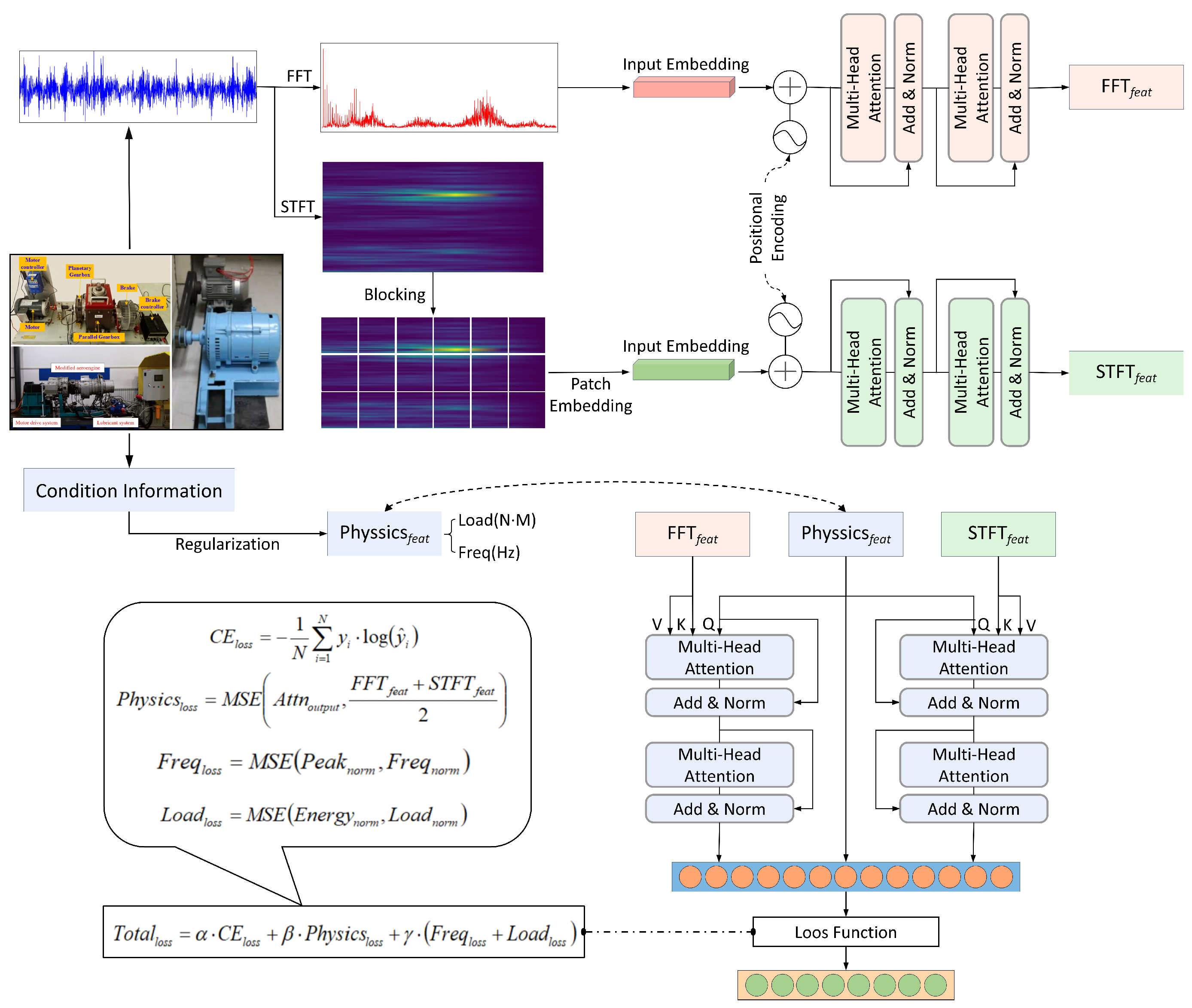
This paper aims to establish a bearing fault diagnosis method based on MSIF-PPK. This method mainly involves the embedding of physical prior knowledge and the fusion of multi-source heterogeneous information. The model architecture used in this paper is shown in
Figure 1.
First, the original vibration signals of bearings in various health states under different working conditions are collected in real time, and detailed working condition text descriptions are recorded simultaneously to ensure the integrity and accuracy of the data.
Second, multi-channel preprocessing is performed on the original vibration signals and working condition text descriptions. At the level of original vibration signals, the bearing state cannot be directly obtained. Therefore, FFT and STFT are used to convert the signals into the frequency-domain level and time–frequency-domain level, thereby extracting clearer fault characteristic frequencies and time-varying patterns. FFT can effectively separate and highlight the periodic impact characteristic frequencies caused by bearing faults, while STFT can simultaneously extract the energy distribution characteristics of the signal in the time and frequency dimensions, capturing the dynamic evolution process of transient fault components in non-stationary signals. At the level of working condition text descriptions, regularization technology is used to extract working condition data from the text information. These converted multi-dimensional feature representations provide a richer and more physically meaningful input basis for the subsequent fusion of physical prior knowledge and multi-source heterogeneous information.
Finally, the information fusion module and physical embedding module are used to realize fault diagnosis. The FFT signals and STFT time–frequency maps are processed and feature-extracted using Transformer and ViT models, respectively, to obtain FFT features and STFT features. Then, these features are transmitted to the information fusion module together with the working condition features, enabling FFT and STFT to pay more attention to the features related to working conditions. After calculating the cross-entropy loss, physical constraint loss, frequency consistency loss, and load consistency loss through the physical embedding module, the final fault classification result is obtained, achieving the task goal.
3. Experimental Verification and Analysis
3.1. Dataset
3.1.1. Southeast University (SEU) Bearing Dataset
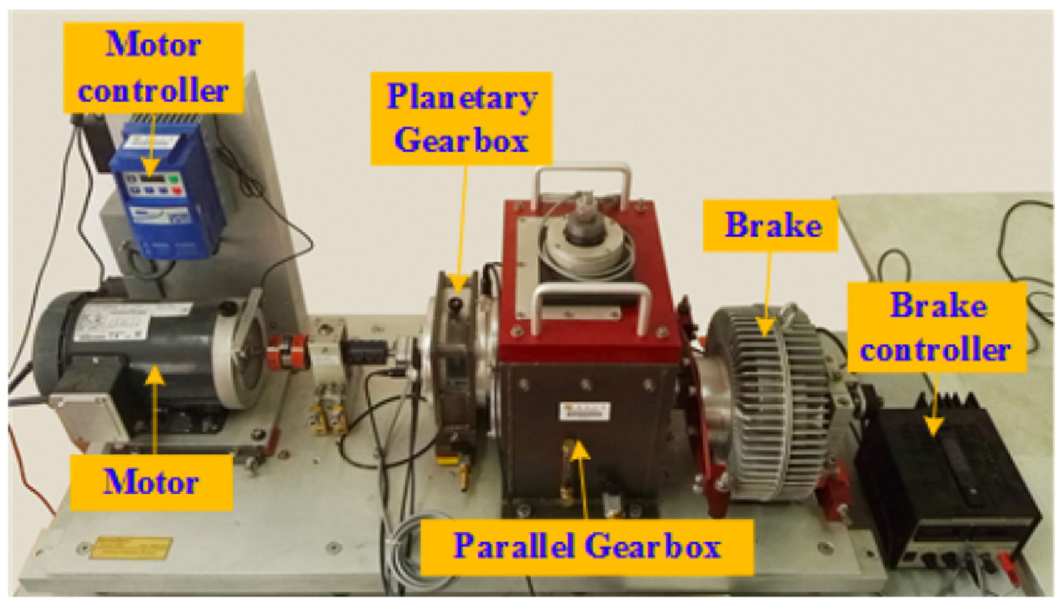
The SEU Bearing Vibration Dataset relies on an experimental platform including a motor, planetary gearbox, reduction gearbox, and load [
39], as shown in
Figure 2. Through this experimental platform, vibration data of bearings under different working conditions are simulated and collected with a sampling frequency of 5120 Hz. The bearing states include healthy, inner race crack, outer race crack, and composite failure of the inner and outer rings. Bearings with different health states are preprocessed (with artificial faults). The motor controller and load controller are used to realize the changes of speed and load, respectively. Two working conditions are simulated: “speed 20 Hz (1200 rpm)-no load 0V (0 N·m)” and “speed 30 Hz (1800 rpm)-load 2V (7.32 N·m)”.
3.1.2. Induction Motor Bearing Vibration Dataset of MUET
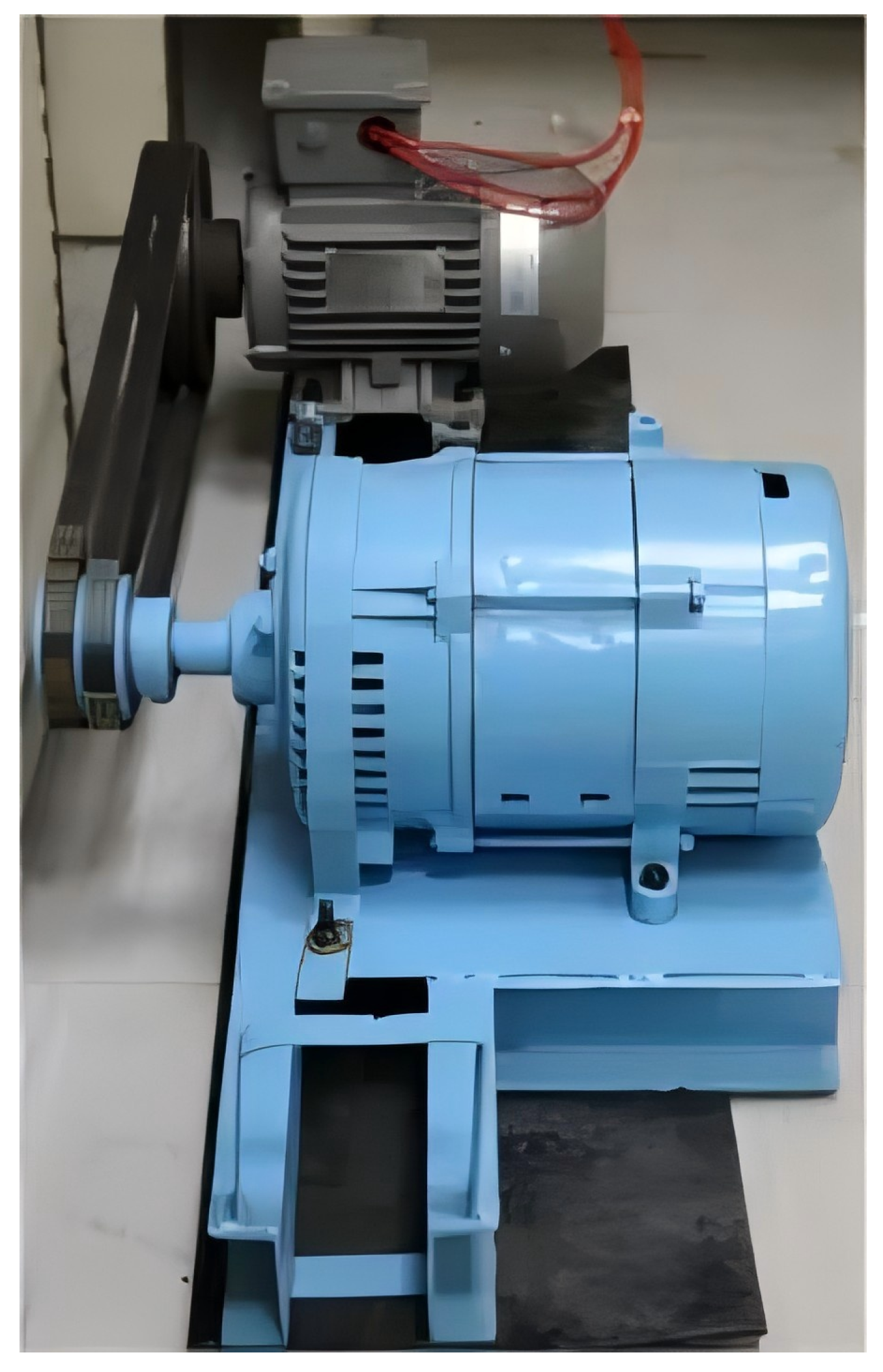
The Condition Monitoring System Laboratory of MUET uses a test bench composed of a three-phase induction motor and an alternator with a variable electrical load system, as shown in
Figure 3. This test bench collects bearing fault states under three load conditions: 100 W, 200 W, and 300 W. The faults are mainly divided into inner race faults and outer race faults with severity levels including 0.7 mm, 0.9 mm, 1.1 mm, 1.3 mm, 1.5 mm, and 1.7 mm.
3.1.3. Aeroengine Bearing Dataset of HIT
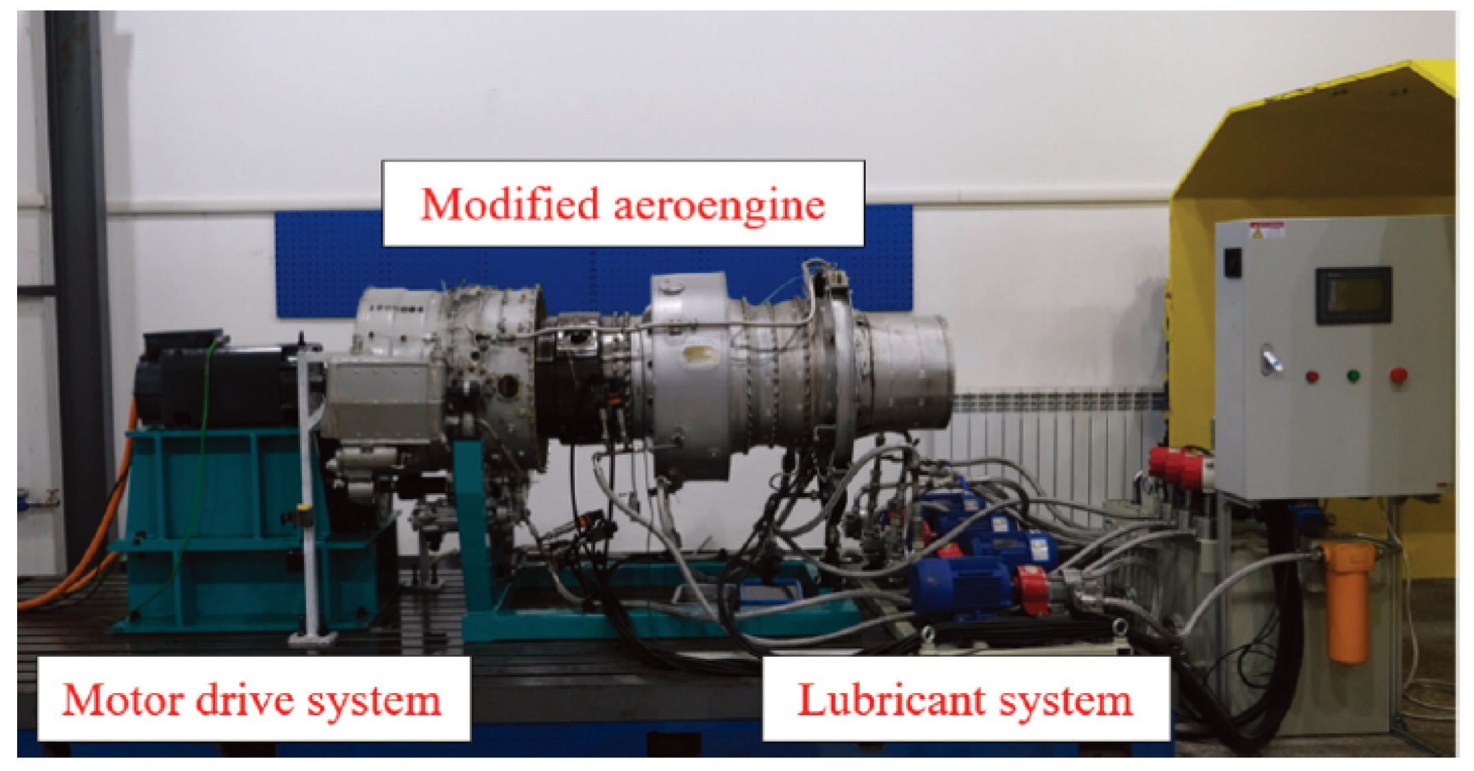
The test bench of HIT mainly consists of three parts: a motor drive system, a modified aeroengine, and a lubrication system [
40]. This test bench adopts a dual-motor drive, which drives the high-pressure rotor and low-pressure rotor, respectively, simulating the dual-rotor structure of aeroengines, as shown in
Figure 4. By adjusting the different speeds of the two motors, the working state and failure characteristics of the aeroengine intermediate bearing are simulated. The fault bearings in the experiment are processed by artificial wire cutting with inner race faults and outer race faults set. The specific fault sizes are shown in
Table 1.
3.2. Design of Experiments
The performance of classification tasks based on Transformer is vulnerable to the number of encoder–decoder layers and the number of heads in the multi-head attention mechanism. To simplify the model structure, this study only utilizes the encoder part of Transformer [
41]. During the experiments, the setting of two attention heads achieved a good balance between performance and computational efficiency, meeting the requirements of the experimental task for modeling capabilities. The specific configurations of the model are detailed in
Table 2.
The software and hardware environment configurations used in the experiments of this paper are shown in
Table 3.
To verify the bearing fault diagnosis performance of MSIF-PPK, different experimental data divisions are carried out for the three datasets.
The SUE Dataset includes two working conditions: “speed 20 Hz (1200 rpm)-no load 0 V (0 N·m)” and “speed 30 Hz (1800 rpm)-load 2 V (7.32 N·m)”. The five fault types are labeled, and corresponding working condition text information is added to the fault categories. During model training, only the data under the working condition of “speed 20 Hz (1200 rpm)-no load 0 V (0 N·m)” are used for training to fully learn the fault features, and the data under the working condition of “speed 30 Hz (1800 rpm)-load 2 V (7.32 N·m)” are used for model testing.
The text information of the MUET Induction Motor Bearing Vibration Dataset mainly includes “fault depth of 0.7/0.9/1.1/1.3/1.5/1.7 mm, motor operating under 100/200/300 W load”, etc. Corresponding text information is set for different working conditions. During model training, another data division method is adopted: only 80% of the data features of all health states are learned, and the remaining 20% of the data is used as the test set for model testing to avoid repeated data testing.
The dual-motor-driven high-pressure rotor and low-pressure rotor of the HIT test bench have 28 speed combinations, as shown in
Table 4. The dataset also includes three types of health states, and the corresponding text information of the fault modes is “low-pressure rotor speed 1000 rpm, high-pressure rotor speed 1200 rpm, fault depth 0.5 mm, fault length 0.5 mm”, etc. Corresponding text information is set for different fault settings. During model training, the third data division method is adopted: only all data of 20 working conditions are trained, and all working conditions are used as the test set for model testing to add new working condition types and verify the model performance.
3.3. Contrast Experiment
To verify the effectiveness of the proposed model, four groups of comparative experiments are set up, using a CNN, LSTM, a Transformer model, and ViT, respectively. To further illustrate the advantages of the proposed model, anti-noise experiments are conducted on the five models, with the Signal-to-Noise Ratios (SNRs) set to 10 dB and 5 dB, respectively.
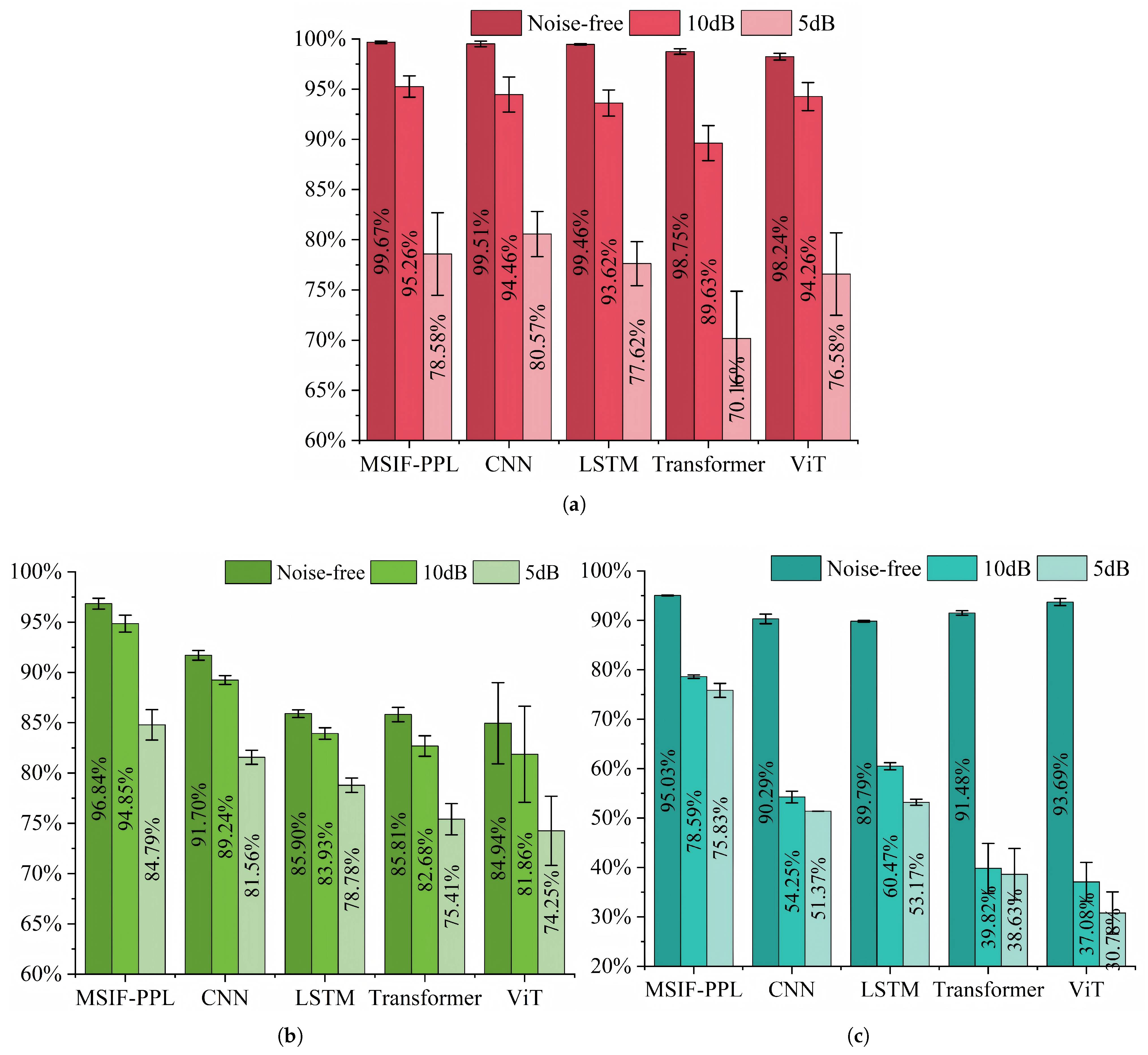
From the experimental results, the following can be concluded from
Figure 5 and
Table 5. (1) In the experiments on any dataset, the experimental results of MSIF-PPK are the best. Facing bearing data from different equipment and working conditions, its adaptability is better than that of comparative models such as CNN and LSTM, and it has strong cross-scenario versatility. (2) Under the 0 dB (noise-free) condition, the recognition accuracy of MSIF-PPK is leading in all datasets (e.g., reaching 99.67% on the SEU, which is better than 99.51% of CNN and 98.52% of Transformer; the advantages vary across datasets but are generally at the top), with high accuracy; under 10 dB and 5 dB noise conditions, the decrease in accuracy is smaller than that of comparative models. Taking the MUET Dataset as an example, MSIF-PPK still has an accuracy of 84.79% under 5 dB strong noise, which is much higher than 75.41% of Transformer and 74.25% of ViT, showing significant anti-noise ability. (3) In the horizontal comparison of all models, MSIF-PPK has better recognition accuracy under most experimental conditions (different datasets + different noises). It not only ensures high accuracy in noise-free scenarios but also maintains stable recognition under noise interference. Its comprehensive performance surpasses single-architecture models such as CNN (focusing on local features), LSTM (time-series processing), Transformer (long-distance dependencies), and ViT (adaptability of vision Transformer), demonstrating more comprehensive bearing fault recognition ability.
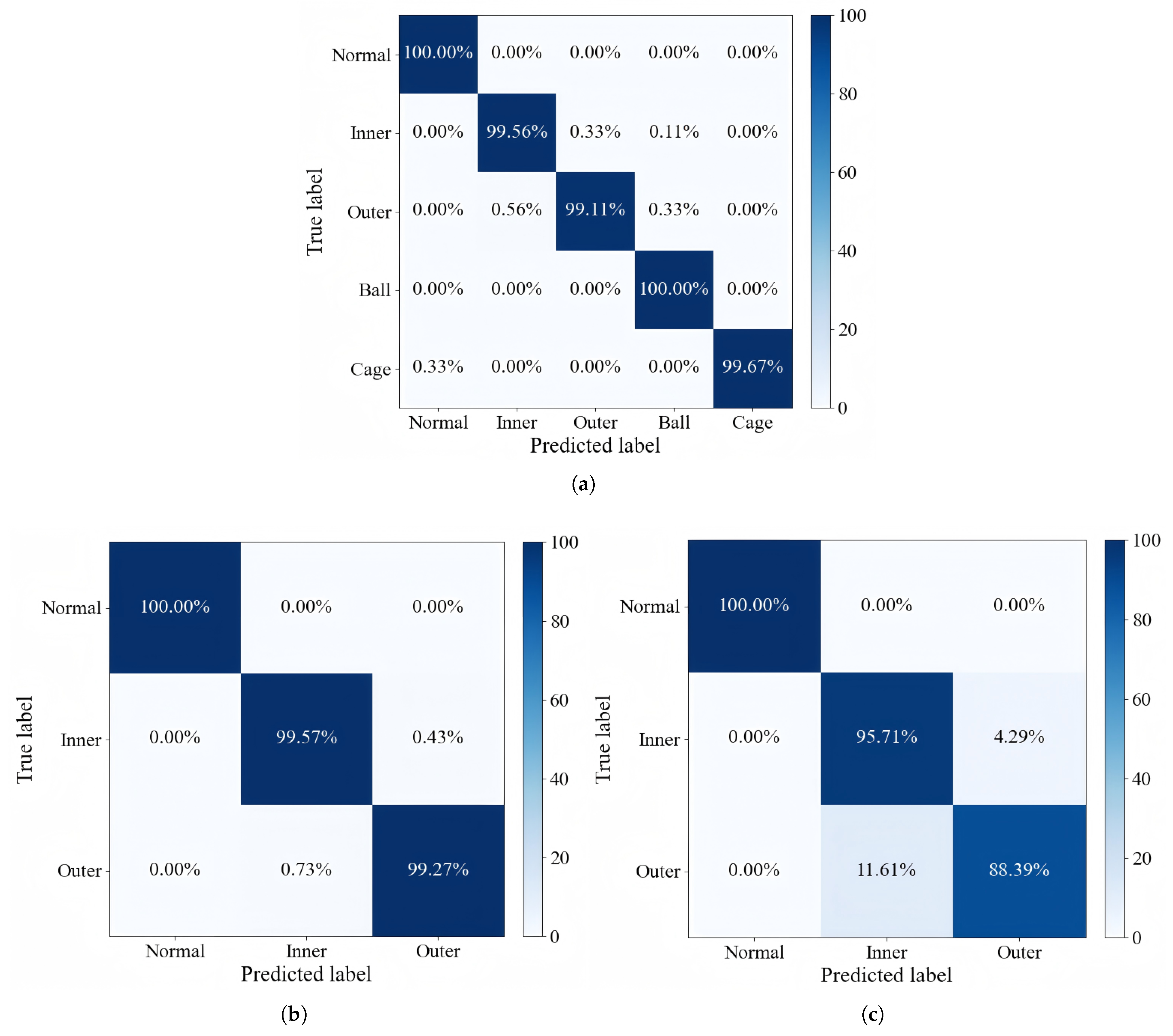
The analysis of the confusion matrices (
Figure 6) further verifies the excellent classification performance of the proposed model in cross-dataset experiments. In the experiment on the SEU Bearing Dataset, the model is trained with samples from a single working condition, and high-precision fault classification under another working condition is successfully achieved (accuracy exceeding 99%). In the experiment on the MUET Induction Motor Vibration Dataset, the model built with 90% of the full working condition training data only has local misjudgments in the remaining 10% of the full working condition test set: the misjudgment rate of inner race faults is 3.09%, and the misjudgment rate of outer race faults is 5.10% with an overall classification accuracy exceeding 96%. In the experiment on the HIT Aeroengine Bearing Dataset, the model is trained with samples from 20 working conditions and evaluated on the test set of the remaining eight working conditions, achieving high-precision classification of multiple fault types: the misjudgment rate of inner race faults is only 2.8%, the misjudgment rate of outer race faults is 4.2%, and the misjudgment rate of rolling element faults is 3.6% with an overall accuracy of 97.5%. Specifically, the confusion matrices show that the model can still maintain stable recognition ability under complex working conditions, which is significantly better than the benchmark models.
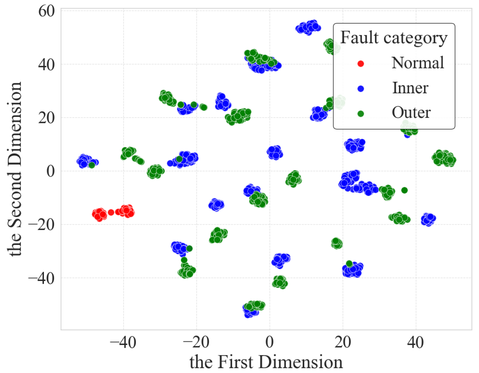
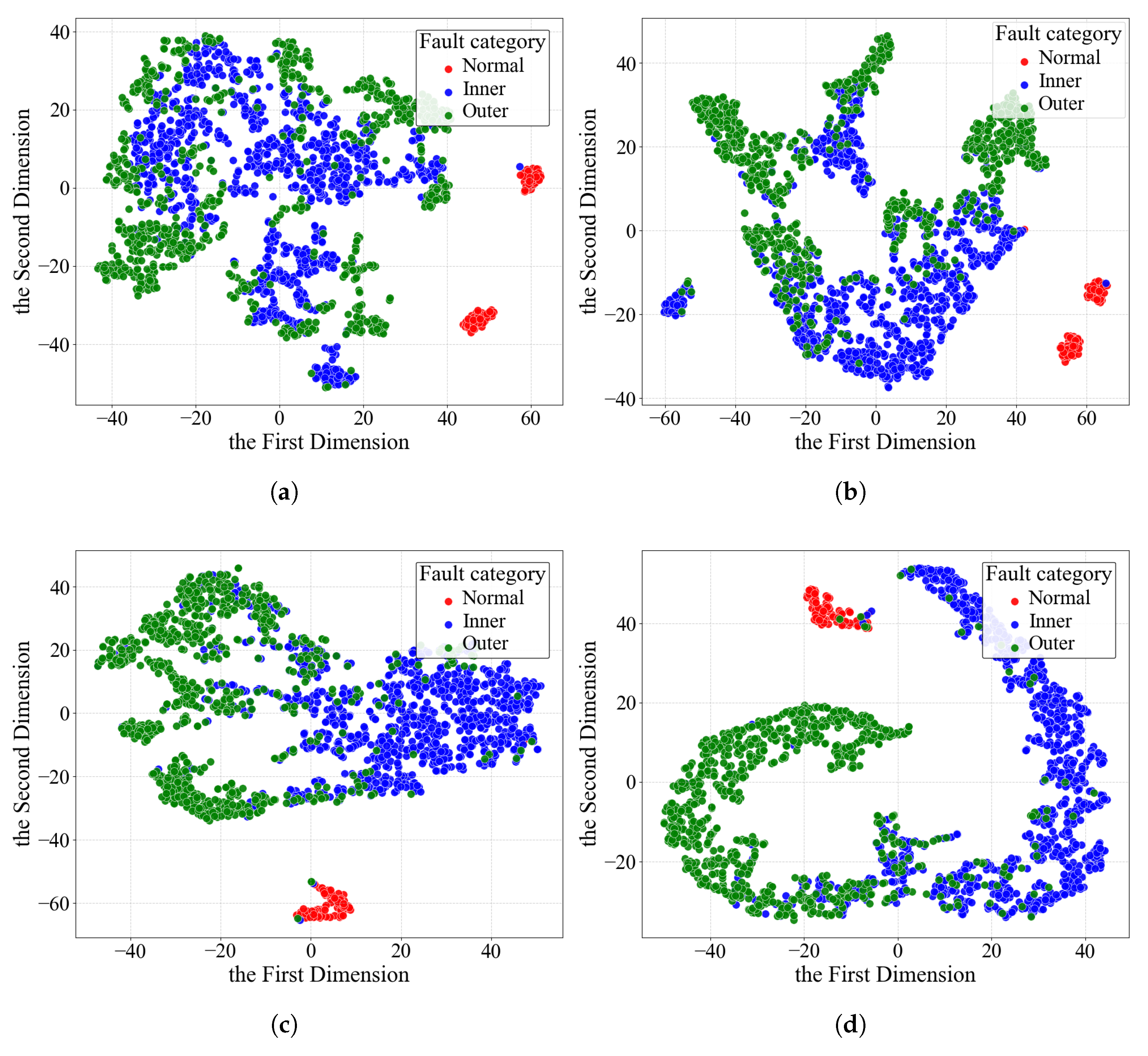
Through the visualization analysis of the feature space, t-SNE dimensionality reduction technology is used to verify the representation ability of the model under complex working conditions, as shown in
Figure 7 and
Figure 8. Based on the MUET Induction Motor Vibration Dataset, the experimental data includes inner race and outer race fault samples (collected under 18 different working conditions) and healthy state samples (collected under two working conditions with/without load). The visualization results show that the fault categories under various working conditions in the feature space of MSIF-PPK exhibit significant inter-class separation characteristics, and their decision boundaries have clear geometric separability. In contrast, the feature distributions of other comparative models in the same dimensionality reduction space show obvious category overlap, especially the poor distinguishability of fault categories.
3.4. Ablation Experiment
To verify the effectiveness of the two modules proposed in this paper, namely the “physical embedding module” and the “information fusion module”, four groups of ablation experiments are designed:
Experiment 1: The original model remains unchanged.
Experiment 2: Remove the physical embedding module and use the traditional cross-entropy loss function.
Experiment 3: Remove the information fusion module and maintain the fusion of 1D FFT features and 2D STFT features.
Experiment 4: Remove both the information fusion module and the physical embedding module.
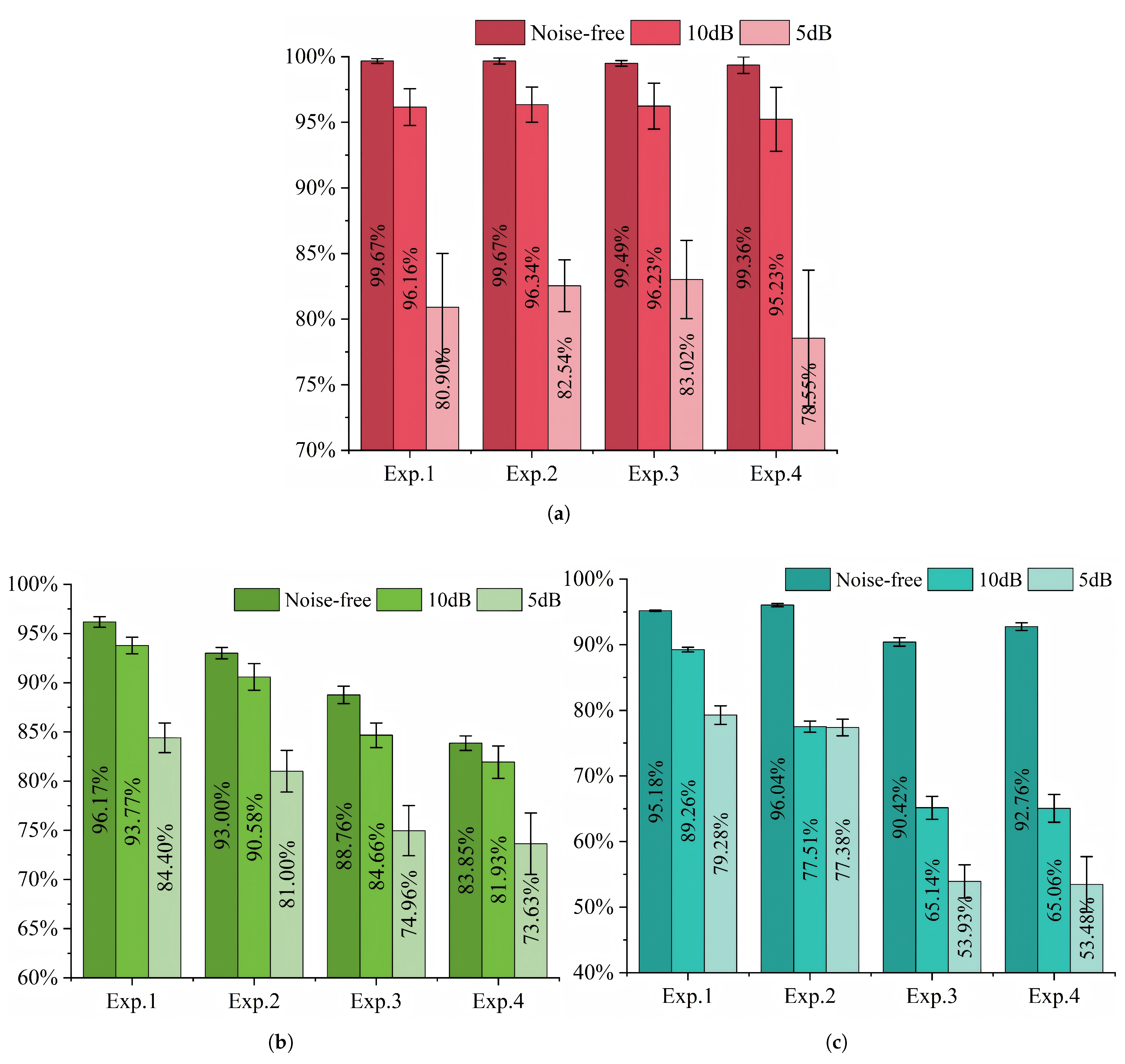
To ensure the accuracy and reliability of the experiments, the method of repeating experiments and taking the average value is adopted, and noise interference is retained. The results of the ablation experiments are shown in
Figure 9 and
Table 6.
In the multi-dataset verification experiments, Exp. 1 maintained the optimal diagnostic performance. Under the same noise intensity, the number of ablated modules was significantly negatively correlated with the bearing fault classification accuracy (Exp. 1 > Exp. 2 > Exp. 3 > Exp. 4).
Traditional intelligent diagnostic models are often restricted in industrial applications due to their black-box characteristics. By embedding physical prior knowledge, the proposed model endows the diagnostic results with clear physical mechanism support (such as the correlation analysis between bearing fault characteristic frequencies and physical models), and it adopts a multi-source feature fusion strategy to ensure engineering practicality (anti-noise interference and adaptability to complex working conditions). Experiment 1 not only meets the accuracy requirements of on-site diagnosis but also can trace the fault evolution path through the physical prior mechanism, forming a “diagnosis–interpretation” closed-loop system. The progressive module ablation experiments show that the diagnostic accuracy of each ablation group shows a significant stepwise decreasing trend, verifying its significant role in improving anti-noise performance.
Comprehensive analysis shows that under most datasets and noise conditions, the “physical embedding module” (realized through the physical prior knowledge loss function) and the “information fusion module” (feature fusion mechanism based on physical working condition information) play a key role in maintaining model performance and improving diagnostic accuracy. Different datasets show heterogeneity in module efficiency under specific noise environments. For example, the model performance of the HIT Aeroengine Bearing Dataset increases abnormally when the physical prior loss function is removed under noise-free conditions. However, in general, the synergistic effect of the two modules significantly enhances the robustness of the model in processing bearing vibration data. The experimental data show that the lack of modules leads to an average accuracy decrease, fully verifying their effectiveness.
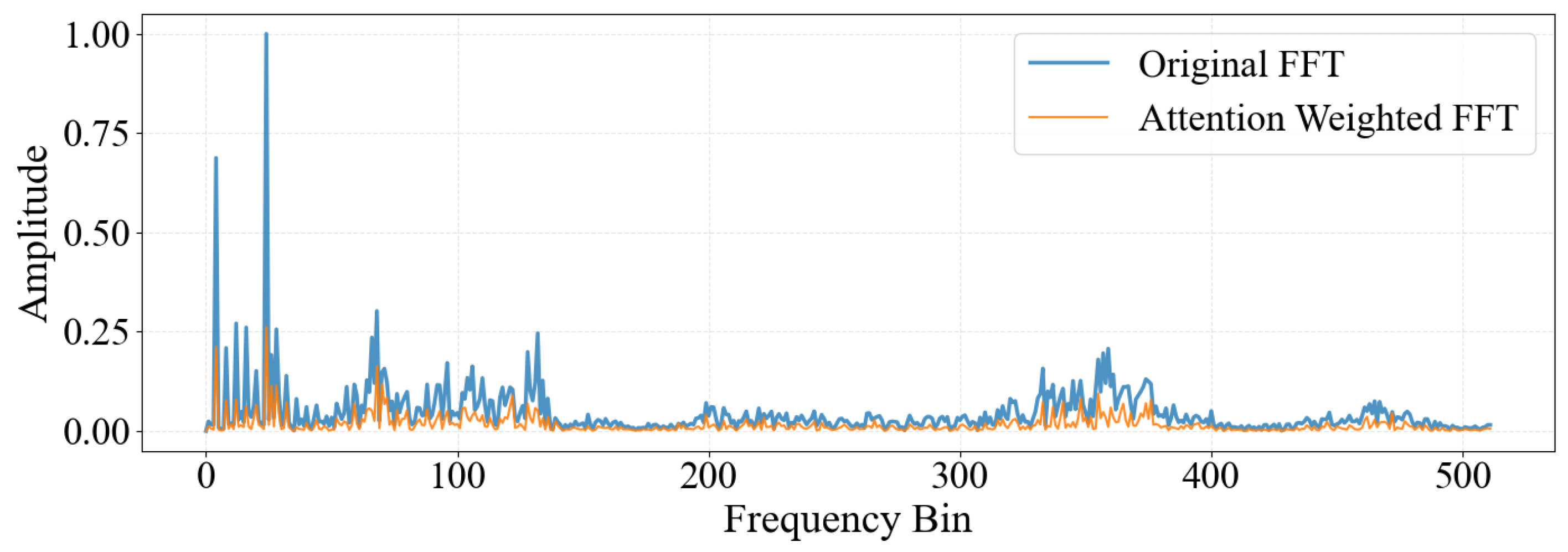
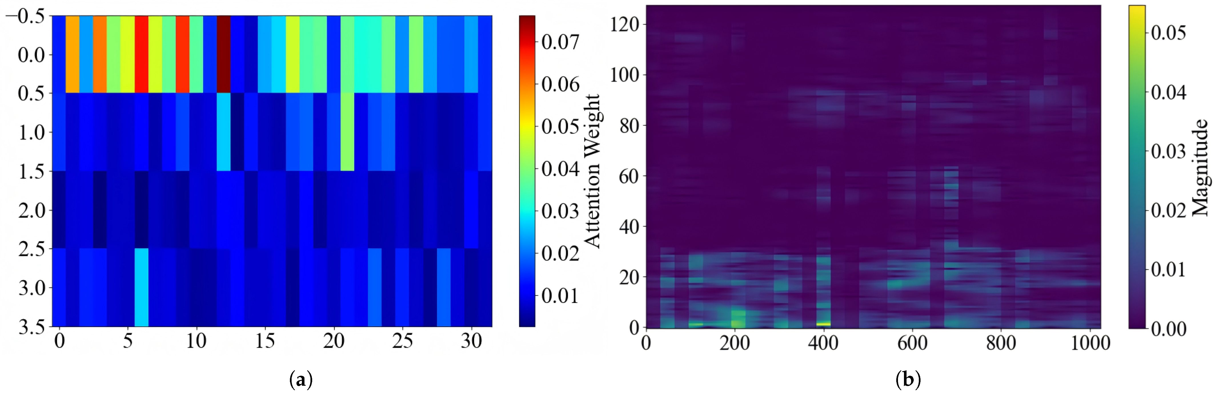
Through the attention visualization analysis of multi-source information fusion, as shown in
Figure 10 and
Figure 11, the key frequency bands are focused on the FFT spectrum and STFT time–frequency map. In the weighted FFT spectrum, more attention is paid to the feature at Frequency Bin 20 according to the working condition features; in the weighted STFT time–frequency map, there are mainly two strong energy blocks, which are two small blocks in the low-frequency part. The model does not process all signals equally. Instead, through the attention mechanism, it adaptively strengthens the key frequency bands and time–frequency regions. This characteristic allows the proposed module to effectively integrate working conditions information. As a result, even in the absence of precise bearing physical parameters, it still demonstrates good feature identification ability and generalization potential.
4. Conclusions
In summary, the main conclusions of this study can be summarized as follows. This paper proposes MSIF-PPK for collaborative fault diagnosis. On one hand, the framework deeply integrates vibration data and working conditions information through an information fusion module based on the attention mechanism, fully uncovering the intrinsic relationships between data and working conditions. On the other hand, it embeds the physical knowledge of bearing health states into the loss function via a physical embedding module, thereby optimizing the training process and enhancing the physical interpretability of the model. To validate its effectiveness, the study systematically demonstrates that MSIF-PPK maintains high classification accuracy under complex conditions, using three challenging datasets: SEU, MUET, and HIT aero-engine bearing datasets, with various data partitioning strategies. Through comparative analysis with baseline models such as CNN, LSTM, Transformer, and ViT, along with confusion matrices and t-SNE feature visualizations, the study further confirms the model’s significant advantages in fault pattern recognition and feature representation. Additionally, stepwise module ablation experiments reveal a progressive decline in diagnostic accuracy upon removing key modules, strongly validating the individual effectiveness of the information fusion module and the physical embedding module in fault diagnosis. In future work, on the one hand, we can explore expanding this framework to a wider range of mechanical system fault diagnosis scenarios and study how to dynamically incorporate online monitoring data and evolving physical knowledge. On the other hand, we can research how to integrate it with largemodel methods to further enhance the model’s generalization and adaptive capabilities.




 ,
,