Article

An Energy Management Strategy for FCHEVs Using Deep Reinforcement Learning with Thermal Runaway Fault Diagnosis Considering the Thermal Effects and Durability

1
College of Information Engineering and Artificial Intelligence, Henan University of Science and Technology, Luoyang 471023, China
2
School of Automation and Electrical Engineering, Zhongyuan University of Technology, Zhengzhou 450007, China
*
Author to whom correspondence should be addressed.
Machines 2025, 13(10), 962; https://doi.org/10.3390/machines13100962
Submission received: 5 September 2025 / Revised: 9 October 2025 / Accepted: 16 October 2025 / Published: 18 October 2025
(This article belongs to the Special Issue Fault Diagnosis and Fault Tolerant Control in Mechanical System)

Abstract

Temperature control plays a critical role in mitigating the lifespan degradation mechanisms and ensuring thermal safety of lithium-ion batteries (LIBs) and proton exchange membrane fuel cells (PEMFCs). However, current energy management strategies (EMS) for fuel cell hybrid electric vehicles (FCHEVs) generally lack comprehensive thermal effect modeling and thermal runaway fault diagnosis, leading to irreversible aging and thermal runaway risks for LIBs and PEMFCs stacks under complex operating conditions. To address this challenge, this paper proposes a thermo-electrical co-optimization EMS incorporating thermal runaway fault diagnosis actuators, with the following innovations: firstly, a dual-layer framework integrates a temperature fault diagnosis-based penalty into the EMS and a real-time power regulator to suppress heat generation and constrain LIBs/PEMFCs output, achieving hierarchical thermal management and improved safety; secondly, the distributional soft actor–critic (DSAC)-based EMS incorporates energy consumption, state-of-health (SoH) degradation, and temperature fault diagnosis-based constraints into a composite penalty function, which regularizes the reward shaping and guides the policy toward efficient and safe operation; finally, a thermal safe constriction controller (TSCC) is designed to continuously monitor the temperature of power sources and automatically activate when temperatures exceed the optimal operating range. It intelligently identifies optimized actions that not only meet target power demands but also comply with safety constraints. Simulation results demonstrate that compared to DDPG, TD3, and SAC baseline strategies, DSAC-EMS achieves maximum reductions of 39.91% in energy consumption and 29.38% in SoH degradation. With the TSCC implementation, enhanced thermal safety is achieved, while the maximum energy-saving improvement reaches 25.29% and the maximum reduction in SoH degradation attains 20.32%.

1. Introduction

With the growing attention to environmental protection and energy security, fuel cell hybrid electric vehicles (FCHEVs) are playing an increasingly crucial role in promoting green transportation and energy transformation [1]. A core challenge in FCHEV design lies in coordinating heterogeneous power sources—proton exchange membrane fuel cells (PEMFCs) and lithium-ion batteries (LIBs)—to simultaneously achieve high fuel economy, long component lifespan, and robust thermal safety. To this end, numerous energy management strategies (EMSs) have been developed, including rule-based methods, optimization-based approaches such as dynamic programming (DP) [2] and Pontryagin’s minimum principle (PMP) [3], and real-time strategies like equivalent consumption minimization strategy (ECMS) [4,5], model predictive control (MPC) [6,7], fuzzy logic [8,9], and genetic algorithms [10,11,12]. More recently, intelligent control methods—particularly deep reinforcement learning (DRL)—have gained traction due to their adaptability and learning capabilities [13,14,15,16,17,18,19,20,21].
However, most existing EMSs prioritize fuel economy while treating durability and thermal safety as secondary considerations. This is problematic because aggressive power allocation can accelerate battery degradation and induce thermal runaway, especially under high-energy-density battery operation. Recognizing this, recent studies have begun integrating state-of-health (SoH) awareness into EMS design. For instance, MPC [22], optimized point-line methods [23], and DRL algorithms—including DQN [24], DDPG [25], TD3 [26], and SAC [27]—have been employed to jointly minimize fuel consumption and SoH degradation. Yet these approaches suffer from significant limitations: they often exhibit poor sample efficiency, unstable convergence, high computational demands, and sensitivity to hyperparameter tuning. Moreover, they typically assume idealized thermal conditions and lack mechanisms to enforce real-time thermal safety constraints, limiting their practical applicability in safety-critical automotive systems.
Concurrently, the rising energy density of LIBs has intensified thermal management challenges. Elevated temperatures not only hasten electrochemical aging but also increase the risk of thermal runaway—a catastrophic failure mode that compromises vehicle safety. Consequently, integrating thermal dynamics into EMS has become imperative. Pioneering efforts in this direction include Zhang et al. [28], who proposed a climate-adaptive EMS that coordinates cabin heating with battery thermal behavior to improve fuel economy in cold environments while preserving battery health. Khalatbarisoltani et al. [29] further advanced this idea by combining multi-agent DRL (MADRL) with LSTM-based driving and thermal prediction models to co-optimize energy use and thermal load. Han et al. [30] proposed a hybrid PMP-MPC framework enhanced with an ANN-based speed predictor that explicitly accounts for electric motor thermal dynamics to reduce operational costs and regulate temperature. Similarly, Abbasi et al. [31] used DRL to jointly optimize charging protocols and cooling strategies, demonstrating up to two years of extended battery life under controlled thermal conditions. Guo et al. [32] developed a thermal-aware EMS that links battery aging mechanisms directly to thermal regulation, achieving a balance between performance and longevity. Most recently, Zhang et al. [33] introduced a DRL-based EMS that embeds thermal effects into power-split decisions, dynamically managing temperature to enhance safety, efficiency, and lifespan.
Despite these advances, a critical research gap remains: existing integrated EMS either lack explicit safety enforcement under thermal runaway or rely on standard DRL frameworks that suffer from Q-value overestimation, high policy complexity, and insufficient robustness in multi-objective optimization. Crucially, none of the cited works [22,23,24,25,26,27,28,29,30,31,32,33] implement a coordinated, dual-layer architecture that proactively prevents thermal runaway while simultaneously optimizing economy, durability, and safety through a distributional reinforcement learning framework.
To address these shortcomings, this paper proposes a novel distributional soft actor-critic (DSAC)-based EMS with thermal runaway fault diagnosis for FCHEVs. Building upon the foundational insights from [28,29,30,31,32,33], our approach introduces three key innovations:
  • To mitigate thermal runaway under high-power operation, this paper proposes a dual-layer protection framework. The upper layer integrates a temperature fault diagnosis-based penalty into the EMS to proactively suppress heat generation. The lower layer employs a real-time safety-constrained power regulator that dynamically adjusts output limits of LIBs and PEMFCs. This strategy-to-execution coordination enables proactive thermal management, improving both system safety and operational reliability.
  • To overcome Q-value overestimation and policy complexity in DRL-based energy management, this work proposes a DSAC-based EMS for FCHEVs. By embedding power loss, SoH degradation, and temperature fault diagnosis-based constraints into a composite penalty function, the method reduces policy dimensionality and achieves multi-objective optimization for economy, durability, and safety. The DSAC algorithm enhances efficiency and accuracy by learning the return distribution via a single network using return variance.
  • To enhance safety under high-temperature conditions, this paper designs a DSAC-based safety-constrained controller for power action optimization. It continuously monitors source temperatures and activates automatically when thresholds are exceeded. The controller intelligently selects actions that meet power demand while satisfying thermal constraints, ensuring safe and efficient operation through real-time, adaptive decision-making.
The structure of this paper is as follows: Section 2 provides gives the SoH and thermal models of FCHEVs. Section 3 presents the optimization framework and control architecture of the proposed EMS, including its training procedure and a thermal safety-oriented soft constraint controller for the power sources. Section 4 presents the simulation results. A conclusion is given in Section 5.

2. Powertrain Model

2.1. FCHEV Powertrain System Overview

The architecture of the FCHEV powertrain system is shown in Figure 1. In this system, the FCHEV is powered by a permanent magnet synchronous motor (PMSM), which drives the rear wheels through a differential and final drive connected to the rear axle of the vehicle. The PEMFC system operates in parallel with a lithium-ion battery, and is connected to the DC bus via a unidirectional boost DC-DC converter. Other auxiliary electronic devices, such as the battery, are powered through a DC-DC converter linked to the DC bus. The power consumption of the thermal management system (TMS) and other auxiliary electronic devices is not considered in this paper. The detailed powertrain parameters provided in Table 1 are adopted from [33].

2.2. Electric–Thermal PEMFC Model

Thermal management is critical during the operation of fuel cells. The heat generated by electrochemical reactions within the fuel cell stack leads to a temperature rise, which can adversely impact the efficiency and lifespan of the fuel cell. Therefore, temperature regulation through the cooling system is essential. The rate of temperature change within the fuel cell stack can be expressed as:
d T f c ( t ) d t = P f c , l o s s ( t ) Q f c , c o o l a n t ( t ) Q f c , e ( t ) m f c C s , f c
where P f c , l o s s ( t ) represents the thermal power generated by electrochemical reactions, Q f c , c o o l a n t ( t ) is the thermal power transferred by the coolant, and Q f c , e ( t ) is the surface heatloss of the stack. m f c and C s , f c are the mass and specific heat capacity of the PEMFCs stack, respectively.
The thermal power P f c , l o s s ( t ) can be calculated as:
P f c , l o s s ( t ) = N c e l l × ( V t h e r m V f c ( t ) ) × I f c ( t )
where N c e l l represents the number of fuel cell units in the stack, V t h e r m ( t ) is the thermoneutral voltage, while V f c ( t ) and I f c ( t ) denote the stack’s voltage and current, respectively.
The thermal power transferred by the coolant, Q f c , c o o l a n t ( t ) , is dependent on the temperature difference between the stack and the coolant, and is generally expressed by the following equation:
Q f c , c o o l a n t ( t ) = h f c , h e a t · A f c · T f c ( t ) T f c , c o o l a n t ( t )
where h f c , h e a t represents the heat transfer coefficient, A f c represents the contact area between the stack and the coolant, and T f c ( t ) and T f c , c o o l a n t ( t ) correspond to the temperatures of the stack and the coolant, respectively.
Q f c , e ( t ) represents the heat loss power from the PEMFCs stack to the environment. Heat is primarily dissipated when the stack temperature exceeds the environment temperature, while reverse heat transfer may occur under cooling conditions. It can be expressed by the following formula:
Q f c , e ( t ) = T f c ( t ) T e R f c
where T f c ( t ) , R f c , and T e represent the PEMFC stack temperature, thermal resistance, and environment temperature, respectively.

2.3. Electric–Thermal LIB Model

In order to optimize the performance and lifespan of the LIBs within the powertrain system, this paper adopts a battery management system (BMS) model. This model not only monitors the state of charge (SoC) of the lithium-ion batteries (LIBs) but also controls the thermal dynamics to ensure that the battery operates within the optimal temperature range. The BMS dynamically adjusts the cooling system’s power output based on real-time monitoring of the battery temperature, thereby regulating the thermal management process.
The temperature variation of the LIBs can be described by the following equation:
d T l i b ( t ) d t = P l o s s ( t ) Q c o o l i n g ( t ) m l i b C s , l i b
where P l o s s ( t ) represents the heat loss due to current transmission, Q c o o l i n g ( t ) denotes the thermal power transferred by the cooling system, and m l i b and C s , l i b are the mass and specific heat capacity of the LlB, respectively.
The heat loss power P l o s s ( t ) can be expressed as:
P l o s s ( t ) = I l i b ( t ) 2 · R l i b ( t )
where I l i b ( t ) is the battery current, and R l i b ( t ) is the equivalent internal resistance of the battery, which varies dynamically with temperature and current rate.
The thermal power transferred by the cooling system, Q c o o l i n g ( t ) , is a function of the temperature difference between the battery and the coolant and can be expressed as:
Q c o o l i n g ( t ) = h c o o l · A c o o l · T l i b ( t ) T c o o l a n t ( t )
where h c o o l is the heat transfer coefficient, A c o o l is the contact area between the coolingsystem and the battery, and T l i b ( t ) and T c o o l a n t ( t ) represent the temperatures of the battery and the coolant, respectively.
d T b , s ( t ) d t = T b , c o o l a n t T b , s ( t ) R b , e x t C b , s T b , s ( t ) T b , c ( t ) R b , i n C b , s
d T b , c ( t ) d t = T b , s ( t ) T b , c ( t ) R b , i n C b , c + P b , l o s s ( t ) C b , c
T b ( t ) = T b , s ( t ) + T b , c ( t ) 2
where T b , s ( t ) , T b , c ( t ) , and T b , c o o l a n t denote the surface, core, and coolant temperatures of the LIB cell, respectively; T b ( t ) is defined as the average of T b , s ( t ) and T b , c ( t ) ; R b , i n and R b , e x t represent the internal and external thermal resistances of the LIB cell; and C b , s and C b , c are the surface and core heat capacities of the LIB cell.

2.4. SoH Models of PEMFCs and LIBs

The degradation of the PEMFCs stack is essentially the accumulation of degradation rates under idle, high power load, load cycling, and start–stop conditions. Since the power output of the PEMFCs stack is continuous during a driving cycle, the start–stop condition is not considered in the calculation of the PEMFCs stack degradation. Therefore, the formula for the decline in the SoH of the PEMFCs stack, denoted as Δ S o H f c ( t ) , is expressed as follows:
Δ S o H f c ( t ) = Δ S o H f c , l o w ( t ) + Δ S o H f c , h i g h ( t ) + Δ S o H f c , Δ P ( t )
where Δ S o H f c , l o w ( t ) , Δ S o H f c , h i g h ( t ) , and Δ S o H f c , Δ P ( t ) represent the SoH degradation rates of the PEMFCs stack under low load operation, high load operation, and load variation operation, respectively.
Δ S o H f c , l o w ( t ) = k l o w Δ t / V f c , i f P f c 0.2 P f c , m a x 0 , e l s e
Δ S o H f c , h i g h ( t ) = k h i g h Δ t / V f c , i f P f c 0.8 P f c , m a x 0 , e l s e
Δ S o H f c , c h g ( t ) = k c h g | P f c ( t ) P f c ( t 1 ) | / ( N c e l l V f c )
where k l o w , k h i g h , and k c h g represent the voltage degradation rates during idling, high power load, and load change periods, respectively. Δ t represents the sampling interval time. The specific values for these parameters can be found in [33].
The performance degradation of lithium batteries is typically manifested as a loss of their maximum remaining capacity, which is commonly characterized by a semi-empirical exponential model [34]. This model expresses the instantaneous capacity loss rate of lithium batteries as a function of current, as follows:
Δ Q b a t ( t ) = M ( c ) e x p ( E a ( c ) R T ) A ( c ) ϕ
where Δ Q b a t represents the capacity loss of the lithium battery, expressed as a percentage, c denotes the discharge rate of the lithium battery, M ( c ) is the exponential prefactor associated with the discharge rate c, R is the ideal gas constant, T is the temperature of the lithium battery, A ( c ) refers to the current throughput of the lithium battery (Ah), φ is the power-law factor, and E a ( c ) represents the activation energy related to the discharge rate c, expressed as:
E a ( c ) = 31700 163.3 c φ = 0.57
it is commonly understood that a lithium battery reaches the end of its life when it experiences a 20% capacity loss. By defining Δ Q b a t = 20 % , the total charge–discharge throughput A t o t a l and the number of charge–discharge cycles N b a t from the beginning of usage to the end of the battery’s life can be determined as follows:
A t o t a l ( c , T c ) = 20 M ( c ) e x p ( E a ( c ) R T ) 1 φ
N b a t ( c , T a ) = A t o t a l ( c , T c ) Q b a t
where Q b a t denotes the rated capacity of the lithium battery. Therefore, the remaining maximum usable capacity of the lithium battery, Q r e m , can be calculated as follows:
Q r e m ( t ) = 0 t | I b a t ( t ) | d t 2 × 3600 N b a t ( c , T c ) Q b a t
the SoH is defined to quantify the degradation of lithium battery performance. By differentiating and discretizing Equation (19), the following formula is derived:
Δ S o H b a t ( t ) = T s | I b a t ( t ) | 2 × 3600 N b a t ( c , T c ) Q b a t
where Δ S o H b a t represents the rate of change in the state of health of the lithium battery.
Based on the SoH models of the two energy sources, the lifespan degradation trends of the lithium-ion battery and fuel cell are accurately quantified. This not only provides a theoretical foundation for the coordinated management of dual-energy systems, but also establishes a solid basis for the design of energy management strategies aimed at lifespan optimization.

3. Design of DSAC-Based EMS with Thermal Flexibility Constraints Considering the Thermal Effects and Durability

The implementation architecture of the DSAC-based EMS framework incorporating thermal constraints is illustrated in Figure 2. First, a DSAC-based EMS considering thermal effects and durability is designed to optimize power distribution in FCHEVs. Second, a flexible-constrained thermal safety controller is developed to ensure the thermal safety of energy sources in FCHEVs.

3.1. Training of EMS

In this paper, the DSAC algorithm is employed to optimize the EMS for a FCHEVs. The core capability of DSAC lies in its ability to learn an optimal policy that maximizes long-term rewards through interaction with the environment, effectively addressing uncertainty and delayed feedback, while maintaining a balance between exploration and exploitation, and demonstrating strong generalization and adaptation capabilities [35]. The iterative process of DSAC consists of four core components: (1) the environment model; (2) the expected value function Q π ( s t , a t ) based on the distributional soft return; (3) the sample transition e t = ( s t , a t , r t , s t + 1 ) ; (4) the stochastic policy π θ ( a t | s t ) parameterized by θ . In this context, the design objective of the control policy π t * is to learn a distributional model of returns for each state-action pair, thereby reducing estimation errors in Q-value approximation and improving both the stability and performance of long-term reward maximization. The optimization goal is to maximize the entropy-regularized total discounted reward while accurately capturing the uncertainty in return distributions, as formulated below:
π t * = arg max π E t = 0 γ t r t + H ( π ( · | s t ) )
where E [ · ] denotes the expectation over environment dynamics and the policy; γ [ 0 , 1 ] is the discount factor; H ( π ( · | s t ) ) is the entropy of the action distribution under the policy at state s t , which encourages exploration; the reward function r t is designed to incorporate multiple key performance indicators, such as fuel economy, component durability, and thermal management effectiveness, to reflect the system’s overall efficiency and reliability at each time step t.
The state space S t of the FCHEVs EMS agent is formulated to represent the key variables influencing energy flow and system performance. It includes two primary parameters: (1) vehicle power demand, and (2) SoC. These variables are essential for making intelligent decisions regarding power allocation between the fuel cell and energy storage system. Specifically, the state vector at time step t is defined as:
S t = [ P r e q , S o C t ]
where P r e q denotes the total power demand of the vehicle at time t, determined by the driver’s torque request and vehicle dynamics; S o C t represents the current state of charge (%) of the lithium-ion battery, which directly affects the allowable discharging/charging behavior and overall energy availability.
This compact yet informative state representation ensures that the DRL agent can effectively learn the trade-off between hydrogen consumption and battery usage, particularly under varying driving conditions. To enable flexible and efficient energy distribution, the action space is designed as a continuous structure, reflecting the adjustable output capability of the fuel cell system. Specifically, the action variable a t corresponds to the fuel cell power output:
a t = P f c ( t ) [ 0 , P f c , m a x ]
where P f c ( t ) denotes the power provided by the fuel cell at time t; P f c , m i n and P f c , m a x are the minimum and maximum allowable fuel cell power output, respectively, constrained by system efficiency and operational safety.
The remaining power required to meet the vehicle demand is supplied by the battery, calculated as:
P b a t ( t ) = P r e q P f c ( t )
This formulation ensures that the total power delivered to the drivetrain satisfies the propulsion requirement, while maintaining flexibility in energy source allocation.
By integrating this structured state-action mapping into the DRL framework, the proposed EMS enables intelligent coordination between the fuel cell and battery systems, leading to improved fuel economy and thermal performance under diverse driving conditions.
The reward terms include hydrogen consumption cost, battery SoC deviation penalty, degradation costs for both fuel cell and lithium-ion battery, and penalties related to temperature deviations from optimal operating ranges. All cost items are assigned negative values to represent energy expenditure or system loss, while weighting coefficients are used to balance the relative importance of each sub-objective. The reward function is defined as follows:
r t = [ Γ H 2 m e q ( t ) + Γ b a t S o C ( t ) + Γ f c Δ S o H f c ( t ) + Γ b Δ S o H b a t ( t ) + Γ b a T b a t ( t ) + Γ f T f c ( t ) ]
where Γ H 2 represents the unit price of hydrogen; m e q ( t ) denotes the equivalent hydrogen consumption of the entire vehicle, incorporating the battery energy consumption converted into hydrogen demand to account for its impact on overall energy use; S o C ( t ) refers to the current battery state of charge (%), with a corresponding penalty term modeled in quadratic form to encourage maintaining SoC within a target range; Δ S o H f c ( t ) and Δ S o H b a t ( t ) , respectively, denote the state of health degradation per percentage for the fuel cell and lithiumion battery; T b a t ( t ) and T f c ( t ) represent the temperature penalty functions for the lithiumion battery and fuel cell, aiming to guide the control policy to operate within optimal temperature ranges, thereby improving training efficiency and reducing component aging rates.
The detailed formulations of all the terms involved are adapted from the theoretical framework of [33] as follows:
Γ H 2 m e q ( t ) = Γ H 2 1 η f c ρ H 2 P f c ( t ) + λ b a t ( t ) P b a t ( t ) Γ b a t S o C ( t ) = μ 1 ( S o C ( t ) S o C i n t ) 2 Γ f c Δ S o H f c ( t ) = Δ S o H f c ( t ) · Γ f c / Γ H 2 Γ b Δ S o H b a t ( t ) = Δ S o H b a t ( t ) · Γ b / Γ H 2 Γ f T f c ( t ) = 0.05 × | T f c 67 | 50 , i f 65 < T f c < 70 0.5 × | T f c 67 | 50 , o t h e r w i s e Γ b a T b a t ( t ) = 0.05 × | T b 33 | 50 , i f 29 < T b < 36 0.5 × | T b 33 | 50 , o t h e r w i s e
where η f c denotes the global efficiency of the fuel cell system, which varies with fuel cell power; ρ H 2 represents the lower heating value of hydrogen; Γ f c and Γ b a t denote the unit prices of the fuel cell stack and battery pack, respectively; T b and T f c are the current temperatures (in °C) of the lithium-ion battery and fuel cell, respectively; S o C i n t is the ideal initial value of the battery SoC; P f c ( t ) and P b a t ( t ) are the output powers of the fuel cell and battery; μ 1 is the weighting factor for the SoC penalty term. The detailed parameter values are shown in Table 2.
Notably, for the temperature fault diagnosis-based penalty functions, a small positive penalty is applied when the temperature lies within the optimal operating range to encourage stable operation; However, once the temperature exceeds safety thresholds, a larger negative penalty is introduced to avoid performance degradation or component damage due to extreme temperatures. In the context of DRL-based EMS for FCHEVs, the design of the state and action spaces plays a critical role in enabling optimal energy distribution and system efficiency. A well-defined state space allows the agent to perceive real-time vehicle operating conditions, while an effective action space facilitates precise control over powertrain components.
This paper leverages DSAC to train the energy management agent FCHEVs, where the state space is expanded to encompass powertrain dynamics. The proposed framework integrates real-time power demand, SoH, and thermal states into the control system, enabling an EMS with near-global optimality.
DSAC learns a stochastic policy that maximizes both expected reward and entropy, thereby achieving more robust exploration and better adaptability under complex driving conditions. The actor network is trained to output a probability distribution over the fuel cell power output P f c [ 0 , P max ] , denoted as π θ ( a | s t ) , from which actions are sampled without explicit noise injection. Before training begins, the replay memory D with capacity M is initialized. Transition tuples ( s t , a t , r t , s t + 1 ) collected during interactions are stored in the experience replay buffer for off-policy learning. When the buffer reaches its maximum capacity, older data are replaced by newer transitions.
Instead of estimating the expected Q-value, DSAC models the entire distribution of returns associated with each ( s t , a t ) pair. Specifically, the critic network outputs a categorical distribution over a set of discrete atoms representing possible Q-values. This distribution is updated using the distributional Bellman operator:
Z θ , w ( s t , a t ) r t + γ Z θ , w ( s t + 1 , a t + 1 )
where a t + 1 π θ ( · | s t + 1 ) , and Z θ , w denotes the target distribution parameterized by the target networks.
The critic loss is defined as the Kullback–Leibler (KL) divergence between the predicted distribution and the projected target distribution:
J ( w ) = E s t , a t , r t , s t + 1 D K L T t a r g e t Z w ( s t , a t )
where T t a r g e t refers to the distribution obtained by projecting the target values onto the support of the learned distribution.
The actor network is updated by minimizing the KL divergence between the current action distribution and the exponentiated Q-values:
θ J ( θ ) = E s t a log π θ ( a | s t ) · Q ( s t , a ) + α a log π θ ( a | s t ) 1 M m = 1 M a log π θ ( a j | s j ) · Q ( s j , a j ) + α log π θ ( a j | s j )
The target networks are updated using a slow-moving average mechanism parameterized by σ θ and σ w , such as in the rule:
w σ w w + ( 1 σ w ) w , θ σ θ θ + ( 1 σ θ ) θ .
This means that the new target actor parameters ( w ) are a weighted average of the current evaluate actor parameters ( w ) and the previous target actor parameters ( w ). The weight σ w determines how much the target network "follows" the evaluate network. Similarly, the new target critic parameters ( θ ) are a weighted average of the current evaluate critic parameters ( θ ) and the previous target critic parameters ( θ ).

3.2. Safe Constriction Control System

To mitigate the safety issues of FCHEVs caused by the unconstrained exploration of RL agents (such as battery overcharging/overdischarging and overheating), a thermal safe constriction controller (TSCC) system has been designed between the RL agent and the control system. This system ensures the reliable operation of the energy sources. The specific design process is as follows: Define the state variables P b a t , T F , T b a t , the output variables P b a t , T F , T b a t , the control variables u 2 = P f c , and the external disturbances ω 2 = P r e q of the energy management system. A flexible constraint controller is designed based on the state variables, as follows:
min P f c J T s c c = P f c ( t ) P f c ( t ) 2 s . t . T f c ( t + 1 ) = T f c ( t ) + P f c , l o s s ( t ) Q f c , c o o l a n t ( t ) Q f c , e ( t ) m f c · C s , f c d t T l i b ( t + 1 ) = T l i b ( t ) + P l i b , l o s s ( t ) Q l i b , c o o l a n t ( t ) m l i b · C s , l i b d t P b a t , m i n P b a t ( t ) P b a t , m a x P f c , m i n P f c ( t ) P f c , m a x P f c ( t 1 ) 100 P f c ( t ) P f c ( t 1 ) + 100
In this equation, P f c represents the output of the TSCC system under the safety intervention of the car-following control system. lt is important to note that when the system state satisfies the safety constraints under the action P f c ( t ) of the vehicle control agent, then P f c = P f c ( t ) , indicating that TSCC does not interfere with the agent’s autonomous exploration. The TSCC becomes active only when the system state fails to meet the safety constraints under the action P f c ( t ) . In such cases, TSCC projects P f c ( t ) onto the nearest action P f c that satisfies the system’s safety constraints through quadratic programming, thereby minimizing the impact on the agent’s exploration process and ensuring the global optimality of the solution. Furthermore, the action P f c ( t ) after safety intervention, along with the corresponding subsequent state, will be stored in the experience replay buffer, which in turn guides the agent in learning the system’s safety constraints.
The pseudo-code of the DSAC-based energy management strategy with energy source thermal constraints is presented in Algorithm 1.
Algorithm 1 DSAC-based energy management and energy source thermal constraint algorithm
  1:
Input: Required power P r e q , State of Charge (SoC) of lithium battery
  2:
Output: Fuel cell output power P f c
  3:
Initialize parameters: maximum training episodes E max , maximum steps per episode n max , actor learning rate α a , critic learning rate α c , temperature parameter learning rate α τ , reward discount factor γ , target network soft update ratio τ , memory pool capacity M , batch size B, target entropy H t a r g e t
  4:
Initialize actor and critic neural networks for both the vehicle control agent and the energy management agent
  5:
Initialize corresponding target networks and experience replay buffer D 1
  6:
Load n max time steps of leading vehicle driving condition data
  7:
for  e = 1 to E max  do
  8:
      Initialize the initial observation state of the fuel cell electric hybrid vehicle (FCEHV)
  9:
      for  k = 1 to n max  do
10:
            Determine the energy management action using the DSAC algorithm:
11:
                   P f c ( t ) = P f c ( t 1 ) + 100 × a ( t )
12:
            if  T b a t T b a t _ m a x  then
13:
                   Retain the original control action: P f c ( t )
14:
            else
15:
                   Compute the safe control action P f c ( t ) according to Equation (31)
16:
                   Deploy safe action: P f c ( t ) = P f c ( t )
17:
            end if
18:
            Execute P f c ( t ) in the EMS, observe next state s ( t + 1 ) , reward R ( t )
19:
            Store transition tuple [ s ( t ) , P f c ( t ) , s ( t + 1 ) , R ( t ) ] into replay buffer D 1
20:
            Update critic network using the defined loss function
21:
            Update actor network via gradient descent with learning rate α a
22:
            Perform soft update on target networks with ratio τ
23:
      end for
24:
      Compute and record average reward: 1 n max k = 1 n max R ( k )
25:
end for

4. Results and Discussion

This paper employs the 2WLTC driving cycle as the benchmark test condition to evaluate the performance of DRL-based EMSs, including the DDPG, TD3, SAC, and DSAC approaches. Each strategy incorporates a multi-objective reward function that considers fuel economy optimization, fuel cell and lithium battery pack lifespan, and thermal management. Particularly, the implementation of TSCC achieves coordinated optimization between system thermal safety and energy distribution efficiency under complex operating conditions.

4.1. Verification Preparation

To support the presentation of subsequent results, Table 3 summarizes the key differences among various DRL algorithms, while Table 4 lists the DRL-based energy management strategies (EMSs) considered in this paper. Specifically, the proposed strategy in this paper is the DSAC-based EMS, which takes into account the thermal, thermal safety, and durability characteristics of the powertrain, along with flexible thermal safety constraints. The DRL-based algorithms, such as DDPG, TD3, SAC, and DSAC, focus on fuel consumption, battery life, and self-heating of lithium-ion batteries and hydrogen fuel cells in the reward function. The definitions of the DRL-based algorithms DDPG_TSCC, TD3_TSCC, SAC_TSCC, and DSAC_TSCC are similar to the previous EMSs, with the main difference being the use of the thermal safety flexible constraints. The driving scenario dataset is shown in Figure 3, where the 2WLTC driving cycle is used for training.

4.2. Energy Distribution Control Verification

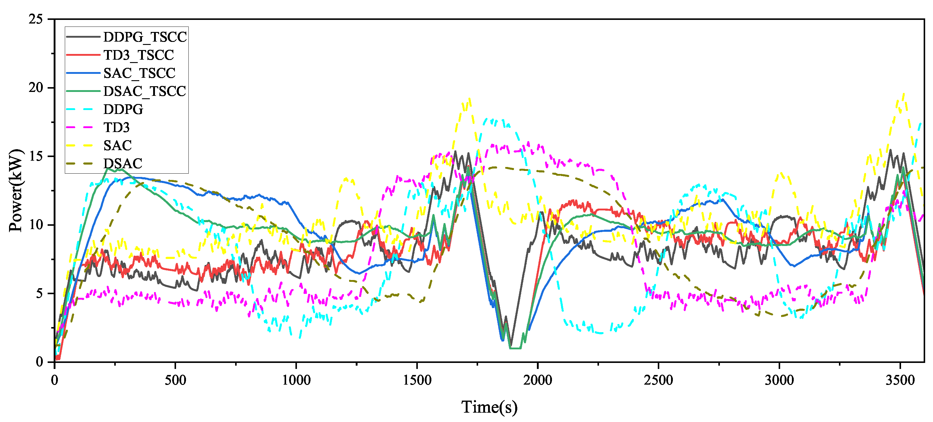
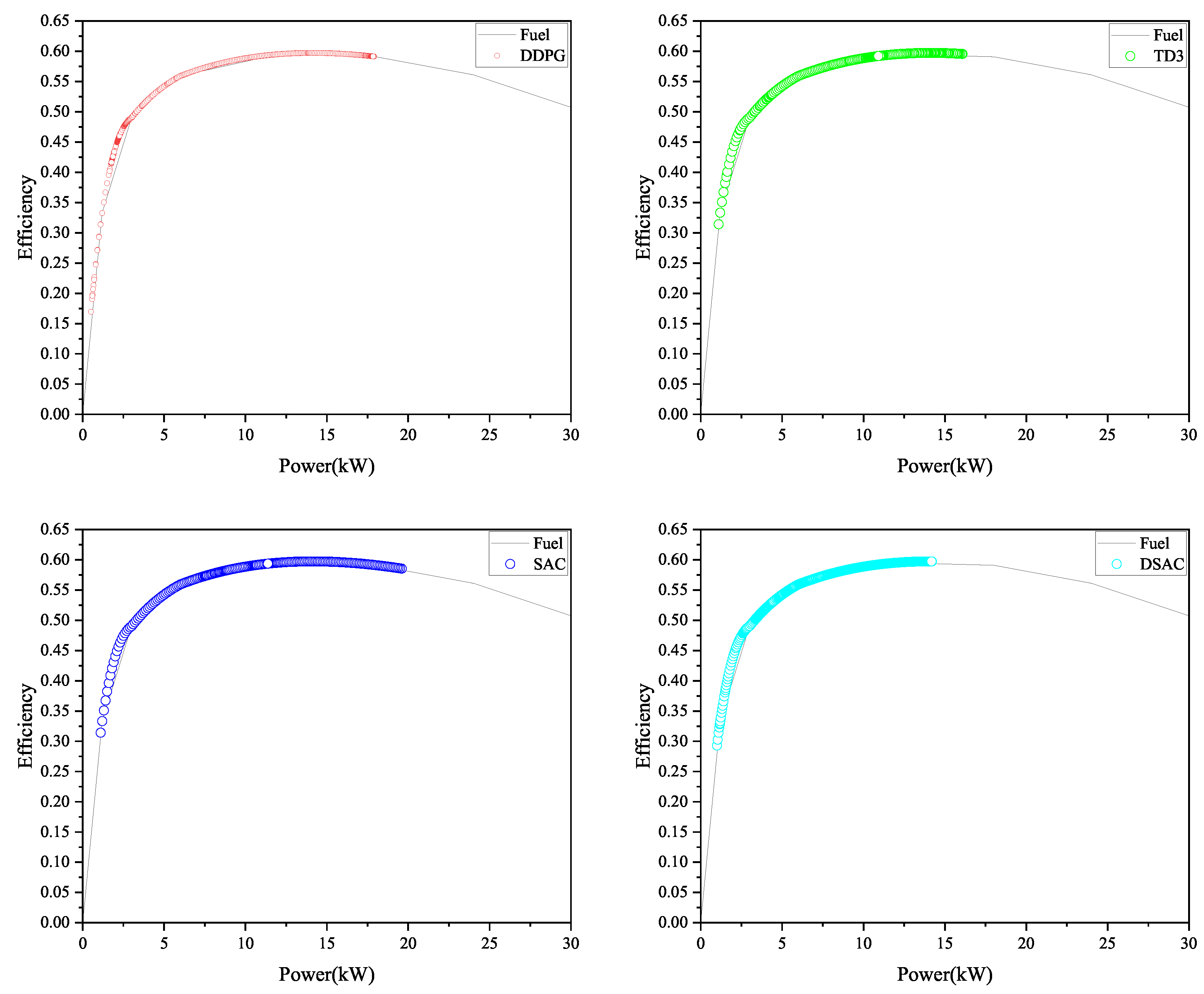
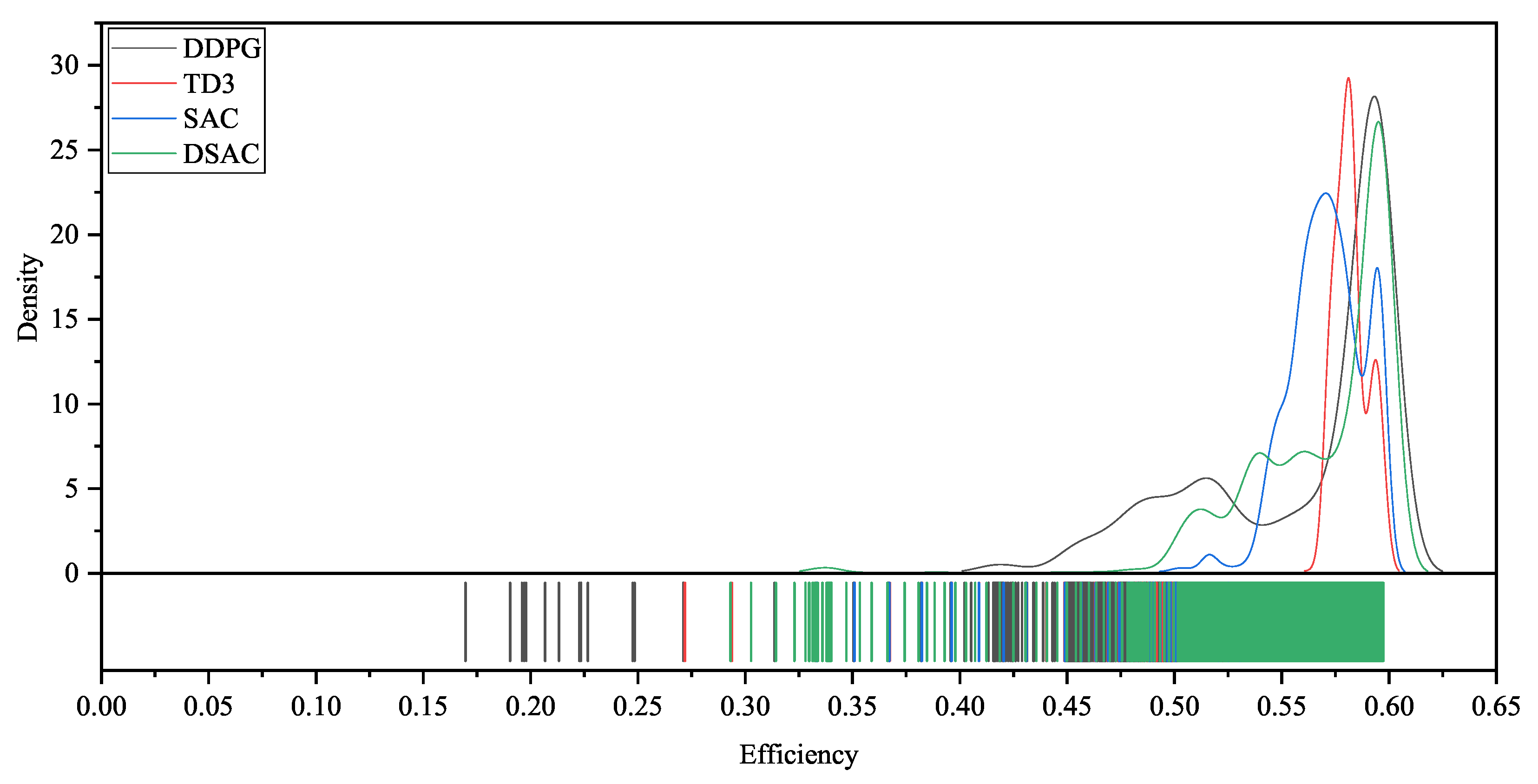
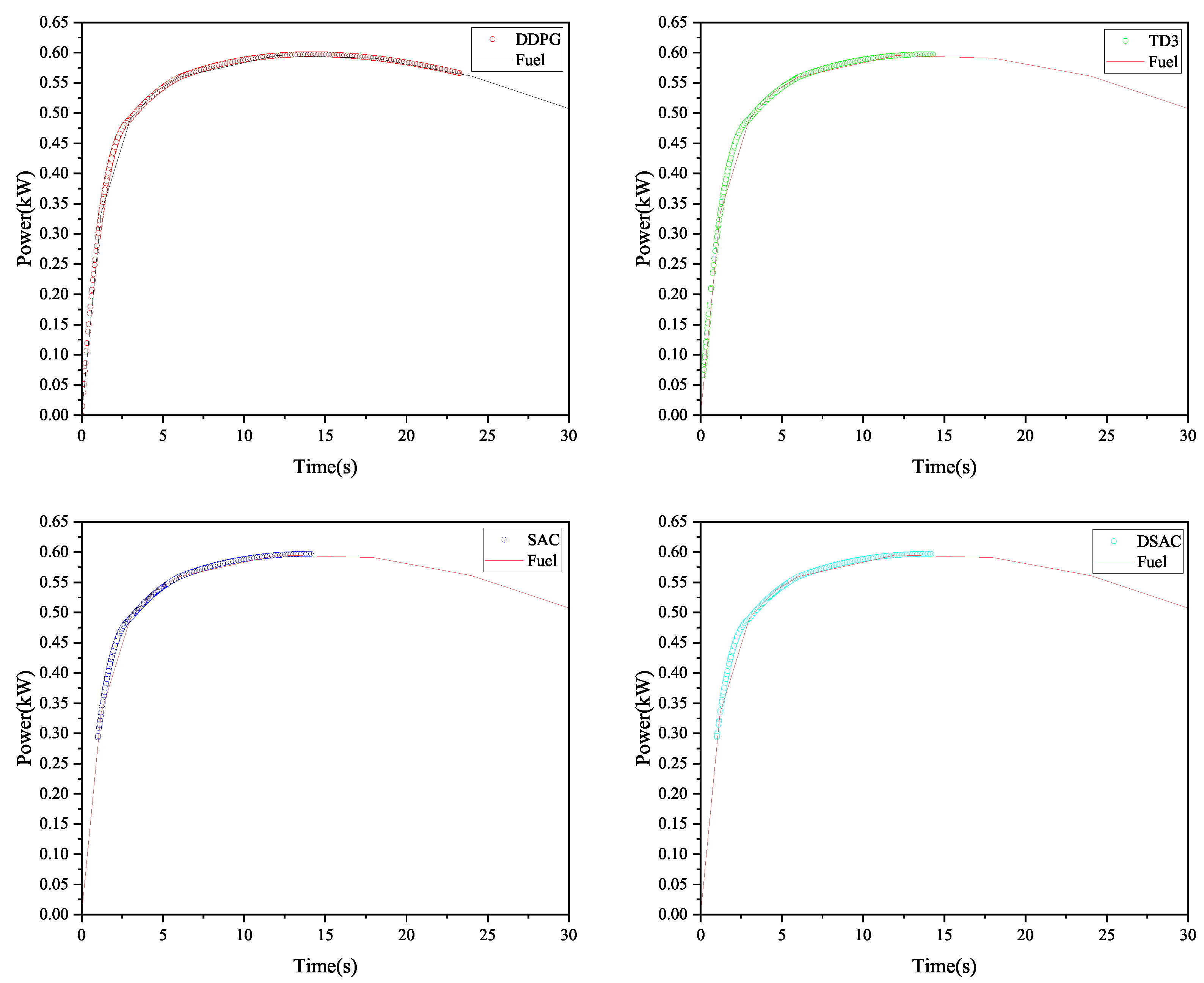
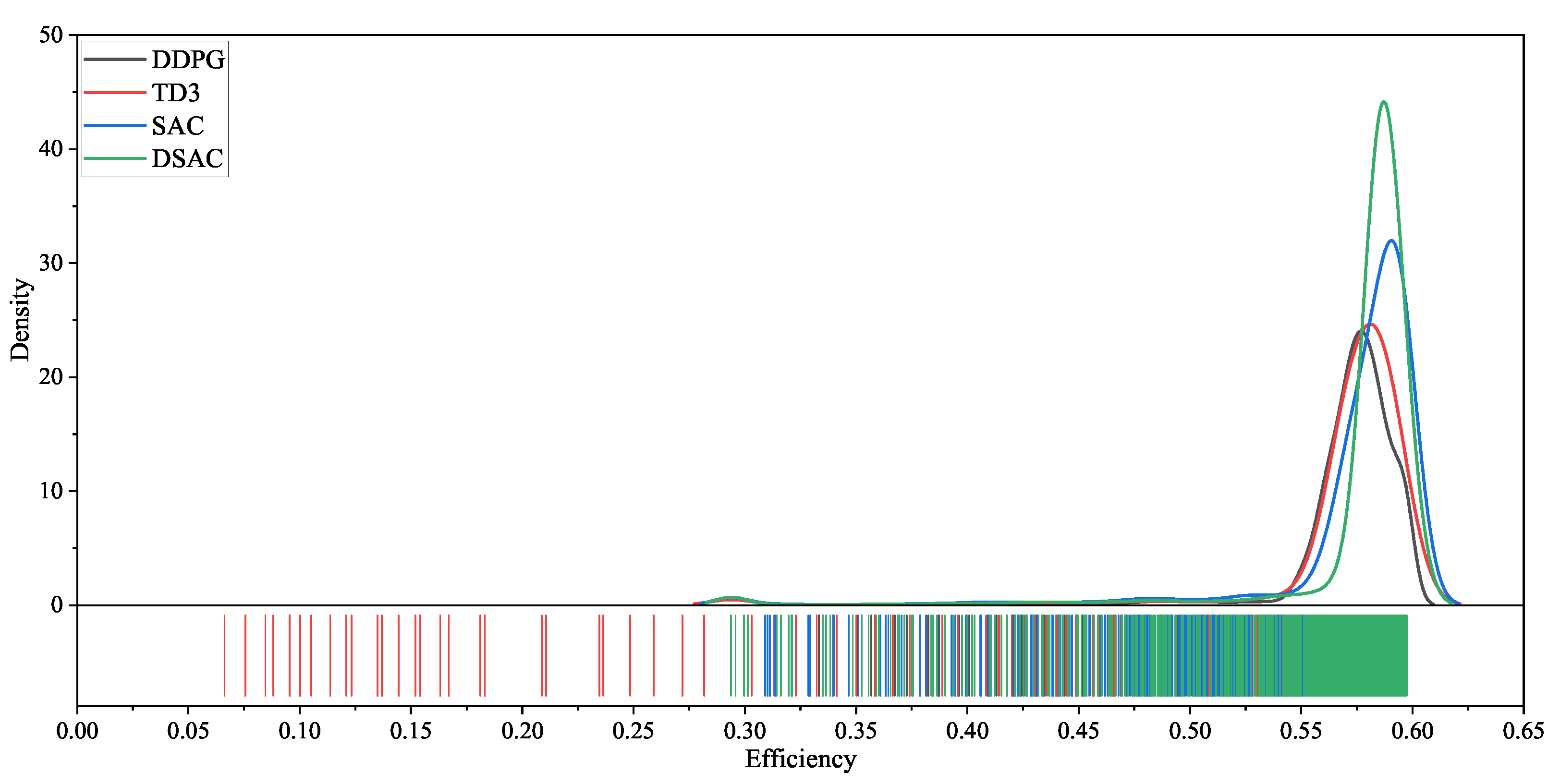
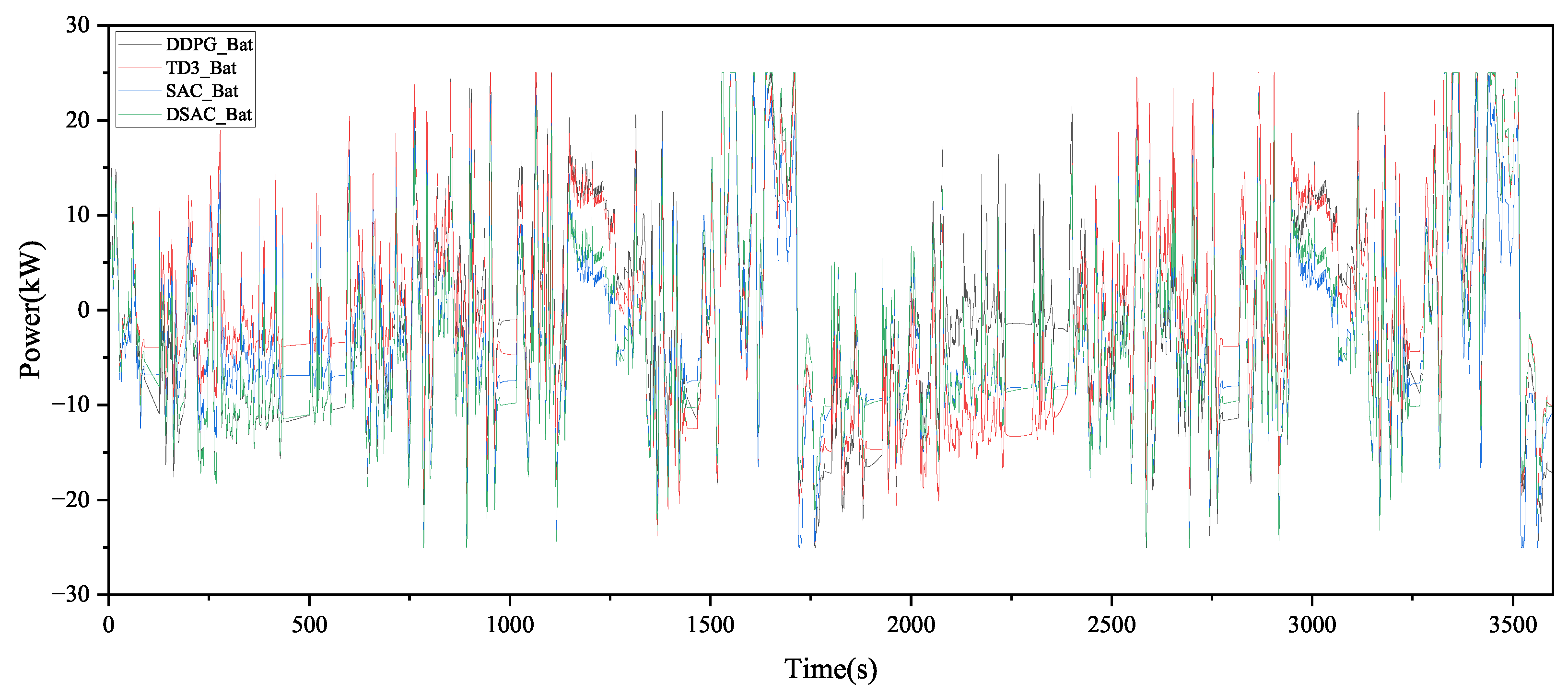
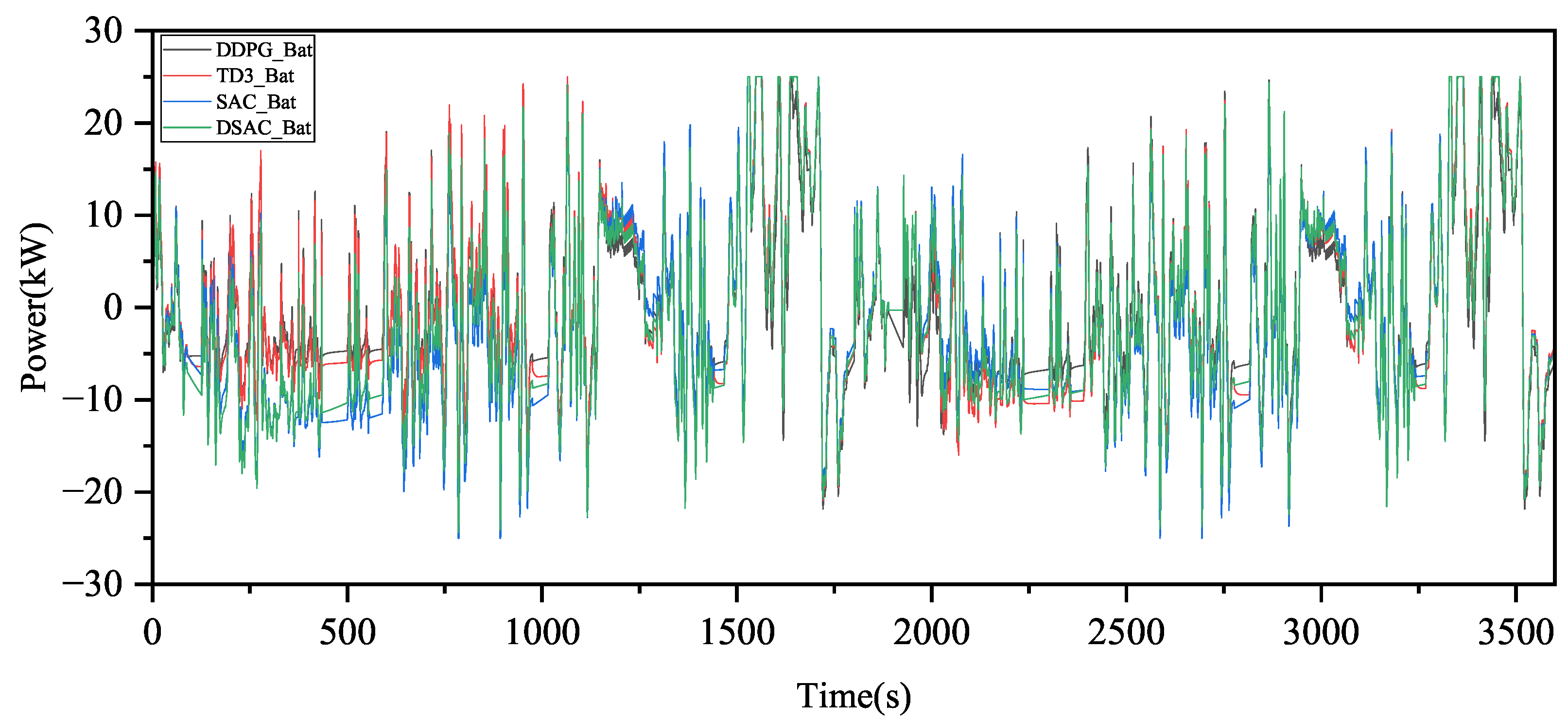
Figure 4, Figure 5, Figure 6, Figure 7 and Figure 8 compare the power distribution performance between the LIBs and PEMFCs stack for the online control of DRL-based EMS. As shown in Figure 4, by using the DSAC-based EMS, the power distribution of the PEMFCs stack is smoother. This indicates that the implementation of the DSAC algorithm, along with the consideration of the powertrain’s thermal and durability characteristics, enables the power distribution to remain more concentrated within the safe operating range of the PEMFCs system, thereby reducing the degradation of the fuel cell’s lifespan due to power fluctuations. As seen in Figure 5 and Figure 7, when the powertrain’s thermal factors are incorporated, DDPG, TD3, SAC, and DSAC algorithms make certain inefficient decisions in power distribution to reduce the generation of heat in the fuel cell. Figure 6 and Figure 8 show that by using the TSCC-based EMS, the power distribution points of the PEMFCs stack become more concentrated, meaning that the implementation of the TSCC algorithm helps focus the power distribution in the higher efficiency region of the PEMFCs system, with the DSAC algorithm showing the most prominent effect. Figure 9 illustrates the frequency distribution of battery power demand across different strategies, highlighting that DSAC-EMS significantly reduces occurrences of high-magnitude power transients—thereby mitigating thermal runaway and aging. Figure 10 shows the battery power trajectories when the TSCC is activated. Compared with Figure 9, the power trajectories of the four algorithms are relatively more concentrated, illustrating how the TSCC actively restricts extreme power outputs to maintain thermal safety. Figure 11 demonstrate that all DRL-based EMSs are capable of maintaining the SoC trajectory and returning the SoC to a level close to the initial value of the LIBs.
Furthermore, the terminal hydrogen consumption for each EMS is listed in Table 5. Due to the exceptional efficiency of the PEMFCs system, the proposed EMS results in lower hydrogen consumption. In Table 5, the corrected hydrogen consumption, expressed as the overall fuel economy of the FCV powertrain, is composed of the hydrogen consumption of the PEMFCs stack and the equivalent hydrogen consumption caused by the varying terminal SoC values of the LIBs. The formula for the corrected hydrogen consumption C H 2 is given as follows:
C H 2 = C f c , H 2 + C b a t , H 2
The equivalent hydrogen costs of the PEMFCs stack and LIBs are represented by C f c , H 2 and C b a t , H 2 , respectively. The total cost of the PEMFCs stack and LIBs corresponding to the DSAC-based EMS is 421.776 g, which is lower compared to other EMS based on DRL.

4.3. Temperature Control Verification

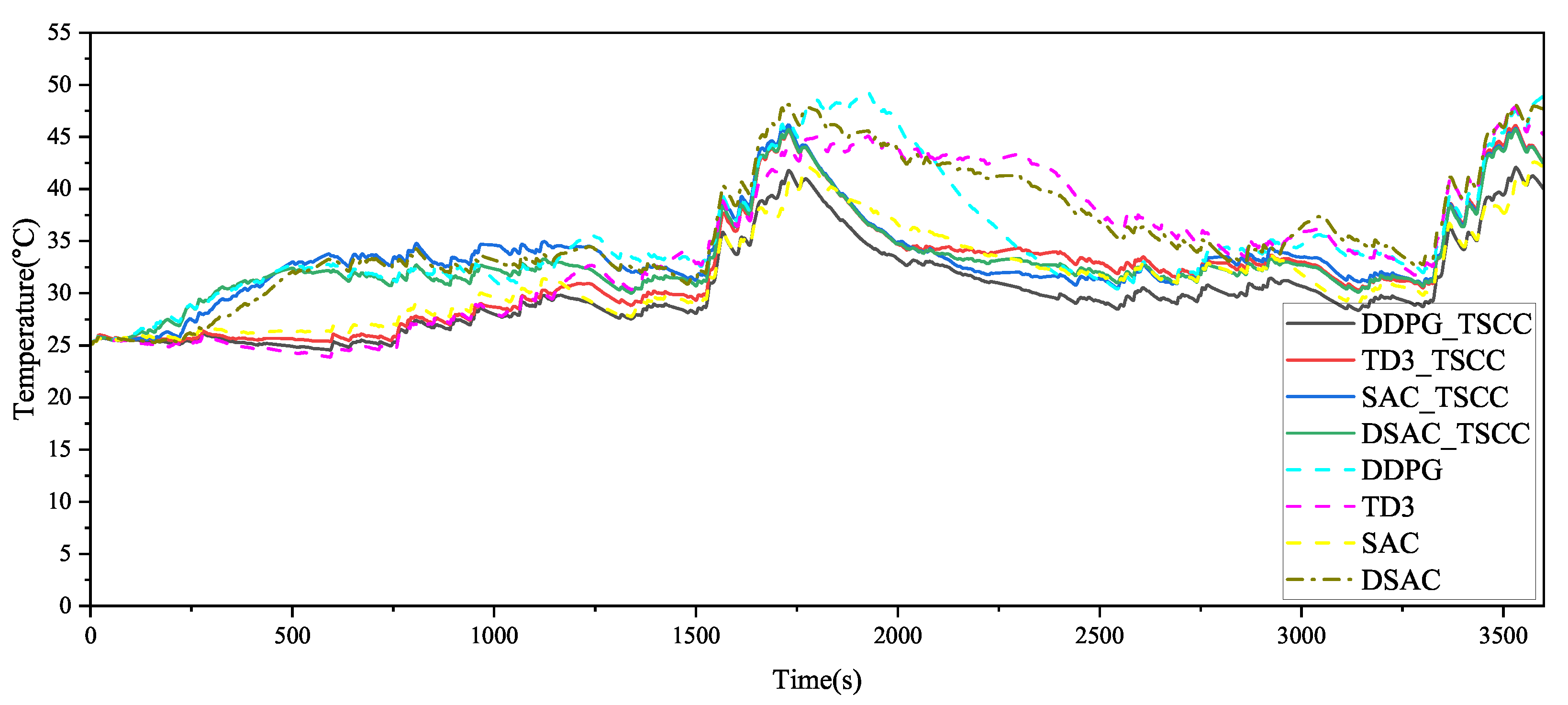
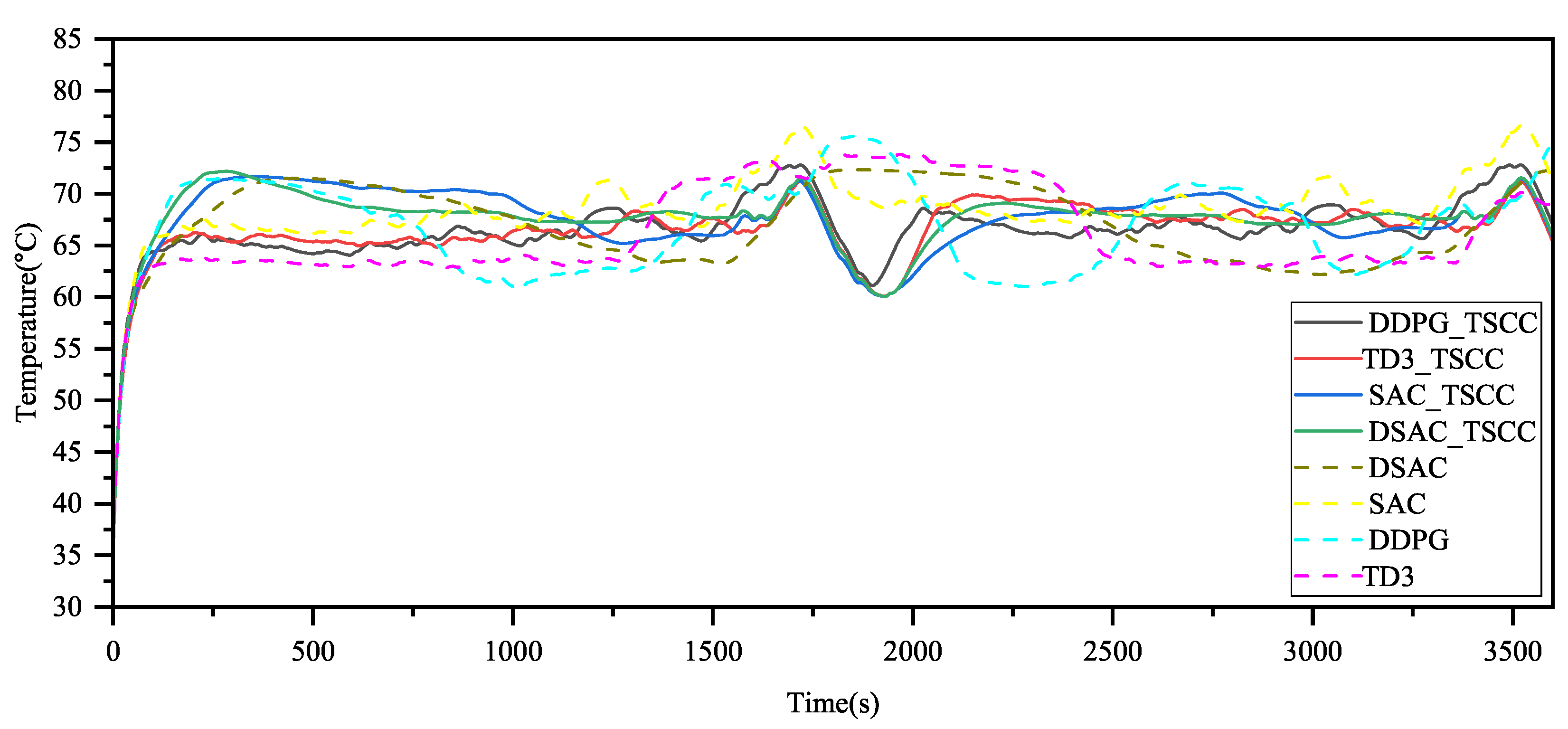
Figure 12 and Figure 13 present the comparative temperature distributions of the PEMFCs stack and LIBs. The results indicate that the operating temperature ranges for the PEMFCs stack and LIBs are 60–76 °C and 25–45 °C, respectively. Since both the PEMFCs stack and LIBs operate within the temperature ranges of 60–80 °C and 20–40 °C, respectively, the temperature curves of the PEMFCs stack and LIBs controlled by the EMS based on DDPG, TD3, SAC, and DSAC are reasonable. In practical engineering, if the battery temperature exceeds 50 °C, the BMS will force a shutdown, halting further operation. The EMS based on DDPG_TSCC, TD3_TSCC, SAC_TSCC, and DSAC_TSCC can effectively regulate the temperature of the LIBs and PEMFCs stack, limiting their maximum temperatures. The temperature curves are smoother, preventing excessive temperatures that could lead to additional losses, while also accounting for the thermal characteristics of the LIBs and PEMFCs stack to avoid overheating.

5. Conclusions

A DSAC-based thermo-electrical co-optimization EMS for FCHEVs is proposed, which explicitly integrates thermal runaway fault diagnosis and a TSCC to address thermal management and safety challenges by jointly considering fuel cell powertrain thermal characteristics, durability, and real-time fault constraints. The overheating penalty of the LIBs and PEMFCs stack, as well as the equivalent SoH degradation cost, are added to the reward space alongside conventional metrics, which include hydrogen consumption and SoC of LIBs penalties used for optimization and training. Additionally, the DSAC-based EMS introduces a single Q-learning technique to prevent Q-value overestimation in the soft Q-network. The validation of the proposed EMS is conducted in several long-term driving scenarios, covering both the training process and online control, with the online control aspects involving fuel economy, thermal stability, and SoH for the PEMFCs stack and lithiumion battery. Simulation results show the following:
  • Under the same operating conditions, considering the thermal characteristics and durability of the powertrain system, the energy consumption saved by the EMS based on DSAC is 17.69%, 39.91%, and 32.46% compared to those based on DDPG, TD3, and SAC, respectively. The SoH consumption is reduced by 26.52%, 29.38%, and 27.69%, respectively. After adding TSCC, the EMS based on DDPG, TD3, SAC, and DSAC achieves energy savings of 0%, 2.03%, 25.29%, and −1.93%, respectively, while SoH consumption is reduced by 6.07%, 3.7%, 20.32%, and 1.65%, respectively.
  • The proposed flexible temperature TSCC effectively regulates the temperature of the LIBs and PEMFCs stack, minimizing their peak temperatures. However, without the introduction of a thermal management system, the energy source temperature cannot be more effectively maintained within the optimal range, which may prevent reductions in energy consumption and mitigate potential lifespan degradation.
  • The method has good versatility and can be extended to other types of FCVs to achieve optimal fuel economy, durability, and thermal safety of the fuel cell vehicle power system in unpredictable driving scenarios.
Despite the promising results achieved in this paper, several limitations warrant further investigation. First, the strategy is developed and evaluated using standard driving cycles (e.g., WLTC, UDDS) under static conditions, focusing on thermal management. However, real-world driving is highly dynamic, with varying traffic, weather, terrain, and driver behavior, which can challenge the DSAC algorithm under thermal constraints. To address this, future work should integrate multi-source data—such as traffic, weather, terrain, and in-vehicle CAN signals (e.g., energy use, temperatures, and driving dynamics)—to develop a more robust and generalizable energy management strategy. This will support validation in complex real-world conditions. To advance toward practical deployment, we plan to conduct hardware-in-the-Loop simulation by deploying the DSAC strategy on a real-time controller and conducting co-simulation with physical models of the fuel cell system, battery management system, and thermal management system. In the long term, the strategy will be further validated on a real vehicle platform to evaluate its energy efficiency, thermal safety, and durability performance. Second, the training of deep reinforcement learning algorithms presents several challenges, including the risk of overfitting to specific driving conditions. Advanced transfer learning and domain adaptation techniques could be investigated to enhance the generalization capability of the strategy across different vehicle models and operating scenarios. Finally, extending this framework to a broader range of new energy vehicle platforms (such as battery electric vehicles and plug-in hybrid electric vehicles) to validate its universality represents an important research direction. Furthermore, integrating our energy management model with intelligent fleet management systems (e.g., the multi-agent collaborative thermal management approach proposed by Khalatbarisoltani et al. [29]) may enable more efficient energy co-optimization.

Author Contributions

Methodology, Y.W.; Software, Y.W.; Data curation, Y.W.; Writing—original draft, Y.W.; Writing—review & editing, Y.W., F.T., L.Z., N.W. and Z.F.; Visualization, Y.W.; Funding acquisition, F.T. and Z.F. All authors have read and agreed to the published version of the manuscript.

Funding

This work was supported in part by the National Natural Science Foundation of China (Grant No. 62301212, 62371182), the Program for Science and Technology Innovation Talents in the University of Henan Province (Grant No. 23HASTIT021), the Major Science and Technology Projects of Longmen Laboratory (Grant No. 231100220200), Aeronautical Science Foundation of China (Grant No. 20220001042002), the Science and Technology Development Plan of Joint Research Program of Henan (Grant No. 222103810036), the Scientific and Technological Project of Henan Province (Grant No. 222102210056, 222102240009, 252102241051).

Data Availability Statement

The data are available from the corresponding author on reasonable request.

Conflicts of Interest

The authors declare no conflicts of interest.

References

  1. Mazouzi, A.; Hadroug, N.; Alayed, W.; Hafaifa, A.; Iratni, A.; Kouzou, A. Comprehensive optimization of fuzzy logic-based energy management system for fuel-cell hybrid electric vehicle using genetic algorithm. Int. J. Hydrogen Energy 2024, 81, 889–905. [Google Scholar] [CrossRef]
  2. Sun, W.; Zou, Y.; Zhang, X.; Guo, N.; Zhang, B.; Du, G. High robustness energy management strategy of hybrid electric vehicle based on improved soft actor-critic deep reinforcement learning. Energy 2022, 258, 124806. [Google Scholar] [CrossRef]
  3. Ma, Y.; Ma, Q.; Liu, Y.; Gao, J. Adaptive optimization control strategy for electric vehicle battery thermal management system based on pontryagin’s minimal principle. IEEE Trans. Transp. Electrif. 2023, 10, 3855–3869. [Google Scholar] [CrossRef]
  4. Rudolf, T.; Schürmann, T.; Schwab, S.; Hohmann, S. Toward holistic energy management strategies for fuel cell hybrid electric vehicles in heavy-duty applications. Proc. IEEE 2021, 109, 1094–1114. [Google Scholar] [CrossRef]
  5. Pu, Z.; Jiao, X.; Yang, C.; Fang, S. An adaptive stochastic model predictive control strategy for plug-in hybrid electric bus during vehicle-following scenario. IEEE Access 2022, 8, 13887–13897. [Google Scholar] [CrossRef]
  6. Wu, Y.; Huang, Z.; Hofmann, H.; Liu, Y.; Huang, J.; Hu, X.; Song, Z. Hierarchical predictive control for electric vehicles with hybrid energy storage system under vehicle-following scenarios. Energy 2022, 251, 123774. [Google Scholar] [CrossRef]
  7. Jia, C.; Qiao, W.; Cui, J.; Qu, L. Adaptive model-predictive-control-based real-time energy management of fuel cell hybrid electric vehicles. IEEE Trans. Power Electron. 2022, 38, 2681–2694. [Google Scholar] [CrossRef]
  8. Shen, Y.; Xie, J.; He, T.; Yao, L.; Xiao, Y. CEEMD-fuzzy control energy management of hybrid energy storage systems in electric vehicles. IEEE Trans. Energy Convers. 2023, 39, 555–566. [Google Scholar] [CrossRef]
  9. Velimirović, L.Z.; Janjić, A.; Vranić, P.; Velimirović, J.D.; Petkovski, I. Determining the optimal route of electric vehicle using a hybrid algorithm based on fuzzy dynamic programming. IEEE Trans. Fuzzy Syst. 2022, 31, 609–618. [Google Scholar] [CrossRef]
  10. Da Silva, S.F.; Eckert, J.J.; Corrêa, F.C.; Silva, F.L.; Silva, L.C.; Dedini, F.G. Dual HESS electric vehicle powertrain design and fuzzy control based on multi-objective optimization to increase driving range and battery life cycle. Appl. Energy 2022, 324, 119723. [Google Scholar] [CrossRef]
  11. Wang, C.; Liu, R.; Tang, A. Energy management strategy of hybrid energy storage system for electric vehicles based on genetic algorithm optimization and temperature effect. J. Energy Storage 2022, 51, 104314. [Google Scholar] [CrossRef]
  12. Xu, Y.; Zhang, H.; Yang, Y.; Zhang, J.; Yang, F.; Yan, D.; Wang, Y. Optimization of energy management strategy for extended range electric vehicles using multi-island genetic algorithm. J. Energy Storage 2023, 61, 106802. [Google Scholar] [CrossRef]
  13. Liu, T.; Tan, K.; Zhu, W.; Feng, L. Computationally efficient energy management for a parallel hybrid electric vehicle using adaptive dynamic programming. IEEE Trans. Intell. Veh. 2023, 9, 4085–4099. [Google Scholar] [CrossRef]
  14. Min, D.; Song, Z.; Chen, H.; Wang, T.; Zhang, T. Genetic algorithm optimized neural network based fuel cell hybrid electric vehicle energy management strategy under start-stop condition. Appl. Energy 2022, 306, 118036. [Google Scholar] [CrossRef]
  15. Ganesh, A.H.; Xu, B. A review of reinforcement learning based energy management systems for electrified powertrains: Progress, challenge, and potential solution. Renew. Sustain. Energy Rev. 2022, 154, 111833. [Google Scholar] [CrossRef]
  16. Sotoudeh, S.M.; HomChaudhuri, B. A deep-learning-based approach to eco-driving-based energy management of hybrid electric vehicles. IEEE Trans. Transp. Electrif. 2023, 9, 3742–3752. [Google Scholar] [CrossRef]
  17. Zheng, C.; Zhang, D.; Xiao, Y.; Li, W. Reinforcement learning-based energy management strategies of fuel cell hybrid vehicles with multi-objective control. J. Power Sources 2022, 543, 231841. [Google Scholar] [CrossRef]
  18. Deng, K.; Liu, Y.; Hai, D.; Peng, H.; Löwenstein, L.; Pischinger, S.; Hameyer, K. Deep reinforcement learning based energy management strategy of fuel cell hybrid railway vehicles considering fuel cell aging. Energy Convers. Manag. 2022, 251, 115030. [Google Scholar] [CrossRef]
  19. Jia, C.; Liu, W.; He, H.; Chau, K.T. Deep reinforcement learning-based energy management strategy for fuel cell buses integrating future road information and cabin comfort control. Energy Convers. Manag. 2024, 321, 119032. [Google Scholar] [CrossRef]
  20. Wang, Y.; Wu, J.; He, H.; Wei, Z.; Sun, F. Data-driven energy management for electric vehicles using offline reinforcement learning. Nat. Commun. 2025, 16, 2835. [Google Scholar] [CrossRef]
  21. Shi, D.; Xu, H.; Wang, S.; Hu, J.; Chen, L.; Yin, C. Deep reinforcement learning based adaptive energy management for plug-in hybrid electric vehicle with double deep Q-network. Energy 2024, 305, 132402. [Google Scholar] [CrossRef]
  22. Engel, J.; Schmitt, T.; Rodemann, T.; Adamy, J. Hierarchical MPC for building energy management: Incorporating data-driven error compensation and mitigating information asymmetry. Appl. Energy 2024, 372, 123780. [Google Scholar] [CrossRef]
  23. Cheng, J.; Yang, F.; Zhang, H.; Yang, A.; Xu, Y. Multi-objective adaptive energy management strategy for fuel cell hybrid electric vehicles considering fuel cell health state. Appl. Therm. Eng. 2024, 257, 124270. [Google Scholar] [CrossRef]
  24. Qi, Y.; Xu, X.; Liu, Y.; Pan, L.; Liu, J.; Hu, W. Intelligent energy management for an on-grid hydrogen refueling station based on dueling double deep Q network algorithm with NoisyNet. Renew. Energy 2024, 222, 119885. [Google Scholar] [CrossRef]
  25. Ouyang, T.; Jin, S.; Xie, X.; Gong, Y.; Zhang, Z. Adaptive Energy Management in Dual-Motor Electric Vehicles Using Deep Deterministic Policy Gradient. IEEE Trans. Transp. Electrif. 2025, 11, 12647–12656. [Google Scholar] [CrossRef]
  26. Chen, B.; Wang, M.; Hu, L.; Zhang, R.; Li, H.; Wen, X.; Gao, K. A hierarchical cooperative eco-driving and energy management strategy of hybrid electric vehicle based on improved TD3 with multi-experience. Energy Convers. Manag. 2025, 326, 119508. [Google Scholar] [CrossRef]
  27. Wang, J.; Du, C.; Yan, F.; Duan, X.; Hua, M.; Xu, H.; Zhou, Q. Energy Management of a Plug-In Hybrid Electric Vehicle Using Bayesian Optimization and Soft Actor-Critic Algorithm. IEEE Trans. Transp. Electrif. 2024, 11, 912–921. [Google Scholar] [CrossRef]
  28. Zhang, H.; Chen, B.; Lei, N.; Li, B.; Li, R.; Wang, Z. Integrated thermal and energy management of connected hybrid electric vehicles using deep reinforcement learning. IEEE Trans. Transp. Electrif. 2023, 10, 4594–4603. [Google Scholar] [CrossRef]
  29. Khalatbarisoltani, A.; Han, J.; Liu, W.; Liu, C.Z.; Hu, X. Health-consciousness integrated thermal and energy management of connected hybrid electric vehicles using cooperative multi-agent deep reinforcement learning. IEEE Trans. Intell. Veh. 2024, 1–12. [Google Scholar] [CrossRef]
  30. Han, J.; Shu, H.; Tang, X.; Lin, X.; Liu, C.; Hu, X. Predictive energy management for plug-in hybrid electric vehicles considering electric motor thermal dynamics. Energy Convers. Manag. 2022, 251, 115022. [Google Scholar] [CrossRef]
  31. Abbasi, M.H.; Arjmandzadeh, Z.; Zhang, J.; Xu, B.; Krovi, V. Deep reinforcement learning based fast charging and thermal management optimization of an electric vehicle battery pack. J. Energy Storage 2024, 95, 112466. [Google Scholar] [CrossRef]
  32. Guo, Z.; Wang, Y.; Zhao, S.; Zhao, T.; Ni, M. Modeling and optimization of micro heat pipe cooling battery thermal management system via deep learning and multi-objective genetic algorithms. Int. J. Heat Mass Transf. 2023, 207, 124024. [Google Scholar] [CrossRef]
  33. Zhang, Y.; Zhang, C.; Fan, R.; Deng, C.; Wan, S.; Chaoui, H. Energy management strategy for fuel cell vehicles via soft actor-critic-based deep reinforcement learning considering powertrain thermal and durability characteristics. Energy Convers. Manag. 2023, 283, 116921. [Google Scholar] [CrossRef]
  34. Han, L.; Yang, K.; Ma, T.; Yang, N.; Liu, H.; Guo, L. Battery life constrained real-time energy management strategy for hybrid electric vehicles based on reinforcement learning. Energy 2022, 259, 124986. [Google Scholar] [CrossRef]
  35. Duan, J.; Guan, Y.; Li, S.E.; Ren, Y.; Sun, Q.; Cheng, B. Distributional soft actor-critic: Off-policy reinforcement learning for addressing value estimation errors. IEEE Trans. Neural Netw. Learn. Syst. 2021, 33, 6584–6598. [Google Scholar] [CrossRef] [PubMed]
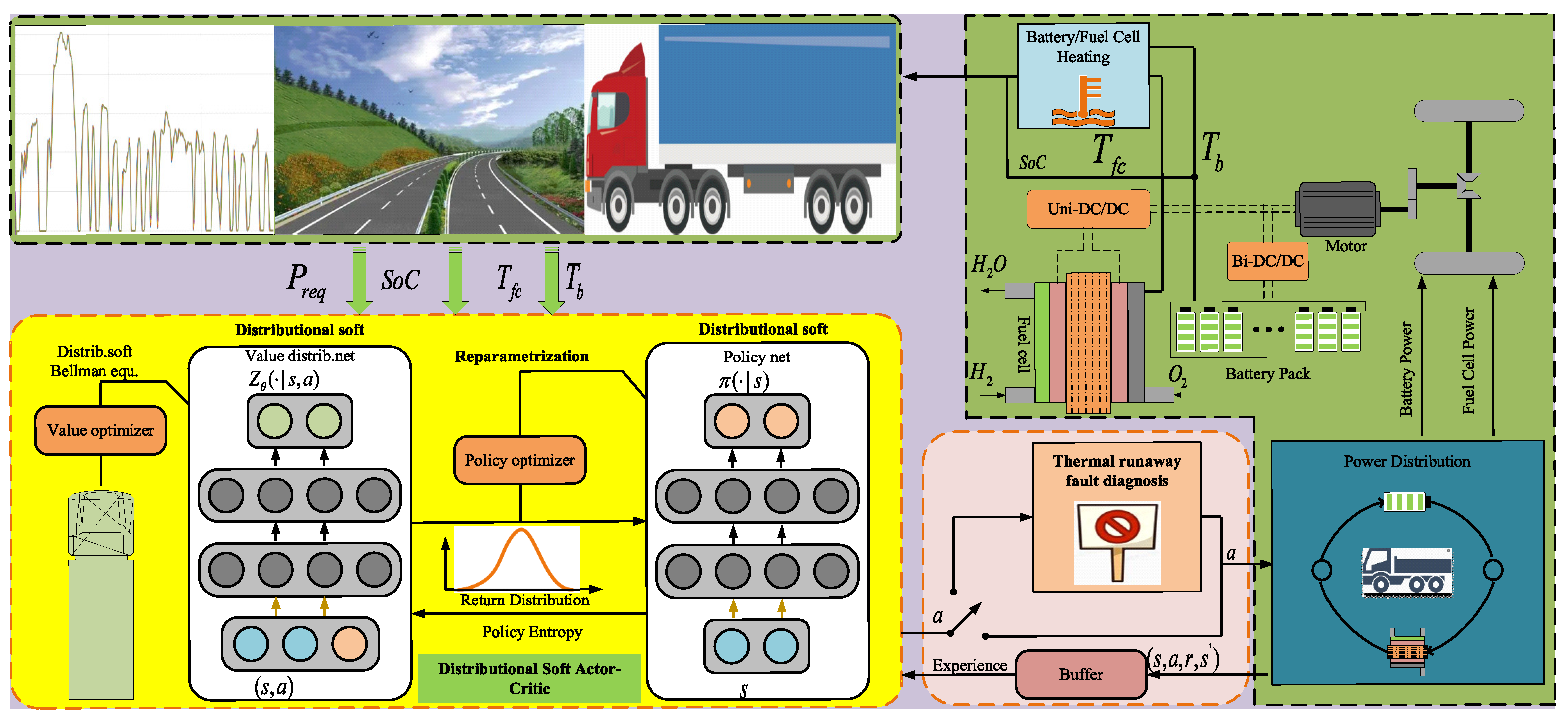
Figure 1. Schematic diagram of intelligent EMS and FCHEV powertrain.
Machines 13 00962 g001
Figure 2. DSAC-based energy management framework with thermal constraints.
Machines 13 00962 g002
Figure 3. 2wltc working condition.
Machines 13 00962 g003
Figure 4. The power distribution results of the fuel cell when using the DDPG, TD3, SAC, DSAC, DDPG_TSCC, TD3_TSCC, SAC_TSCC, and DSAC_TSCC algorithms.
Machines 13 00962 g004
Figure 5. The efficiency distribution diagram of the fuel cell when using the DDPG, TD3, SAC, and DSAC algorithms.
Machines 13 00962 g005
Figure 6. The efficiency distribution statistics of the fuel cell when using the DDPG, TD3, SAC, and DSAC algorithms.
Machines 13 00962 g006
Figure 7. The efficiency distribution diagram of the fuel cell when using the DDPG_TSCC, TD3_TSCC, SAC_TSCC, and DSAC_TSCC algorithms.
Machines 13 00962 g007
Figure 8. The efficiency distribution statistics of the fuel cell when using the DDPG_TSCC, TD3_TSCC, SAC_TSCC, and DSAC_TSCC algorithms.
Machines 13 00962 g008
Figure 9. The power distribution results of the lithium-ion battery when using the DDPG, TD3, SAC, and DSAC algorithms.
Machines 13 00962 g009
Figure 10. The power distribution results of the lithiumion battery when using the DDPG_TSCC, TD3_TSCC, SAC_TSCC, and DSAC_TSCC algorithms.
Machines 13 00962 g010
Figure 11. The SoC variation curves of lithiumion batteries when using the DDPG, TD3, SAC, DSAC, DDPG_TSCC, TD3_TSCC, SAC_TSCC, and DSAC_TSCCalgorithms.
Machines 13 00962 g011
Figure 12. The temperature distribution results of the lithiumion battery when using the DDPG, TD3, SAC, DSAC, DDPG_TSCC, TD3_TSCC, SAC_TSCC, and DSAC_TSCC algorithms.
Machines 13 00962 g012
Figure 13. The temperature distribution results of the PEMFCs stack when using the DDPG, TD3, SAC, DSAC, DDPG_TSCC, TD3_TSCC, SAC_TSCC, and DSAC_TSCC algorithms.
Machines 13 00962 g013
Table 1. FCHEV parameters.
PropertyParameterValueUnit
FCV mass m f c 2046kg
Equivalent windward area A f 2.62m2
Wheel radius r w 0.35m
Gear ratio of final drive i t r a n s 9
Table 2. Parameters in Equation (26) and their definitions.
ParameterPhysical MeaningTypical Value/RangeUnit
η fc Global efficiency of the fuel cell system0.45–0.60
ρ H 2 Lower heating value (LHV) of hydrogen33.3
Γ fc Fuel cell degradation per percentage point of SOH loss750$
Γ H 2 Unit price of hydrogen16$/kg
Γ bat Unit price of the lithiumion battery pack200$/kWh
Γ b Lithiumion battery degradation per percentage point of SOH loss375$
Γ ba Lithiumion battery temperature penalty weight−10
Γ f Fuel cell temperature penalty weight−10
μ 1 Weighting factor for the SoC penalty term10
T fc Current operating temperature of the fuel cellOptimal: 65–70 °C°C
T b Current operating temperature of the lithium-ion batteryOptimal: 29–36 °C°C
S o C init Ideal initial state-of-charge of the battery0.5–0.6
P fc ( t ) Real-time output power of the fuel cellVaries with demandkW
P bat ( t ) Real-time output power of the batteryVaries with demandkW
Table 3. Comparison of DRL algorithms for EMS.
AlgorithmDistributional LearningMaximum EntropyDouble Q-NetworkContinuous ActionSuitable for EMS
DDPGnononoyesyes
TD3nonoyesyesyes
SACnoyesyesyesyes
DSACyesyesnoyesyes
Table 4. EMSs algorithm table.
AlgorithmFuel ConsumptionTemperature and SoHThermal Safety Constraints
DDPGConsideringConsideringNeglecting
TD3ConsideringConsideringNeglecting
SACConsideringConsideringNeglecting
DSACConsideringConsideringNeglecting
DDPG_TSCCConsideringConsideringConsidering
TD3_TSCCConsideringConsideringConsidering
SAC_TSCCConsideringConsideringConsidering
DSAC_TSCCConsideringConsideringConsidering
Table 5. Performance indicators of 2wltc driving cycle under different EMS strategies.
Strategy/Driving CycleAlgorithmEffective Fuel Consumption (kg)Energy Loss ($)
RL WLTCDDPG0.5030.494
TD30.6890.514
SAC0.6130.502
DSAC0.4140.363
TSCC-RL WLTCDDPG0.5030.464
TD30.6750.495
SAC0.4580.400
DSAC0.4220.357
Disclaimer/Publisher’s Note: The statements, opinions and data contained in all publications are solely those of the individual author(s) and contributor(s) and not of MDPI and/or the editor(s). MDPI and/or the editor(s) disclaim responsibility for any injury to people or property resulting from any ideas, methods, instructions or products referred to in the content.