1. Introduction
The mine scaler manipulator arm executes scalping and cleaning in narrow underground tunnels [
1]. It operates under severe spatial constraints, high impact loads, and frequent duty cycles [
2]. Its kinematic architecture—modeled as a multi-loop planar kinematic chain—must ensure accessibility, posture control, and structural reliability. As in other construction machinery, configuration choices largely determine operational performance and engineering feasibility. These demanding operating conditions ultimately require subsequent dimensional design and performance verification (e.g., stiffness and load-carrying capability); however, the present study focuses on the upstream topology-level synthesis and application-oriented screening to generate feasible configuration candidates. An automated, systematic configuration synthesis is therefore essential to shorten design cycles, reduce trial-and-error, and improve design quality. Despite substantial progress, configuration synthesis for planar multi-loop mechanisms remains incomplete and only loosely connected to engineering practice for mine scalers. Advancing systematic configuration synthesis and the automatic generation of feasible configurations is a key pathway to improving the design efficiency of high-end equipment [
3,
4].
Since the 1960s, graph theory has supported structural synthesis by representing planar kinematic chains with topological graphs and adjacency matrices [
4]. With the aid of computer programs, the synthesis process became amenable to automation, and with increasing computing power, automatic synthesis has become a mainstream direction. The long-term objective is an end-to-end workflow that proceeds from a candidate topological graph atlas to functional screening and then to engineering validation under explicit structural and functional constraints. In this context, planar multi-loop fractionated kinematic chains (FKCs) with multiple joints (MJs) are considered. An FKC can be decomposed into two or more coupled subchains via joint- or link-based separation, whereas a non-fractionated kinematic chain (NFKC) cannot be decomposed in this manner. The mine scaler manipulator arm is selected as the application case. An 18-link, 5-DOF (degrees of freedom) FKC with two MJs (denoted as
N18_
M5) is investigated; a topological graph atlas is constructed, and connectivity-calculation-based functional screening is performed, followed by engineering implementation. Task functionality, installation-space limits, and actuator layout constraints are incorporated while balancing completeness and computational efficiency.
For planar NFKCs, a relatively complete framework now exists for atlas construction, isomorphism discrimination, and automatic sketching. In 1967, Dobrjanskyj and Freudenstein [
5] first applied graph theory to isomorphism detection of KCs and discussed automatic generation and sketching of topological graphs. Since the 2000s, rising computing power has accelerated automatic synthesis. Butcher and Hartman [
6] synthesized planar 1-DOF KCs with up to 14 links from contracted graphs and detected rigid subchains by successively removing binary-vertex chains. Lu et al. [
7,
8] proposed an array approach to automatically synthesize KC topological graphs from the corresponding contracted graphs. Yan and Chiu [
9,
10], using graph-theoretic techniques, built generalized KC atlases with up to 16 links. Ding et al. [
11] developed a systematic, fully automatic method and constructed a planar NFKC atlas with up to six independent loops and 19 links. Sun et al. [
12] identified similar vertices and edges using powers of the adjacency matrix and the minimum distance matrix, and automatically generated NFKC atlases with up to seven independent loops and 3-DOF.
For FKCs, prior work examined subchain-composition rules and the effect of MJs on isomorphism. Davies and Crossley [
13] used vertex notation to establish fractionated simple-joint chains with up to 10 links. Using the binary-chain transformation technique [
14], Mruthyunjaya et al. [
15,
16] constructed fractionated simple-joint kinematic chains with up to 11 links. Yan and collaborators [
17,
18] applied contracted graphs to enumerate fractionated multiple-joint kinematic chains with up to 10 links and used permutation-group theory to enumerate fractionated simple-joint KCs with up to 12 links. Hwang and Hwang [
19,
20] proposed six degenerate-chain tests and enumerated fractionated simple-joint KCs with up to 13 links. Martins et al. [
21] applied the Boost graph library method to eliminate generating isomorphic chains and obtained FKCs with two to four independent loops. Nie et al. [
22] created an addition technique to count planar FKCs. Ding et al. [
23] built a computer-aid system to enumerate planar KCs and obtained fractionated simple-joint kinematic chains with up to 18 links. Huang et al. [
24] developed a heuristic method to enumerate all planar 2-DOF fractionated multiple-joint kinematic chains and established the atlas with up to 17 links. Meanwhile, recent studies have increasingly emphasized performance-oriented mechanism design and evaluation, such as geometry-informed design, reliability assessment under uncertainty, and stiffness-related analysis for complex robotic mechanisms [
25,
26,
27]. These efforts reflect an important trend toward engineering performance; however, the present study focuses on the upstream topology level, where a complete and reproducible set of feasible candidates is generated to support subsequent dimensional synthesis and performance optimization. Overall, most studies still focus on low-DOF FKCs or exclude MJs, and few provide workflows and specifications tightly coupled to a defined engineering target [
28,
29,
30,
31]. A systematized summary of the identified problems and representative solutions is provided in
Table 1. Despite these efforts, an end-to-end pipeline for atlas construction and connectivity-calculation-based screening of high-DOF planar multi-loop FKCs with MJs remains limited, which motivates this study.
To address this gap, an automatic synthesis-and-screening framework is proposed for planar multi-loop FKCs, and an engineering-oriented workflow is established to support application-driven configuration design. A mine scaler manipulator arm is used as a case study, where an 18-link, 5-DOFFKC with two MJs and three non-fractionated subchains (KC1, KC2, KC3) is investigated. Each subchain is treated as a basic unit. Two fractionation rules—joint-fractionation (A-mode) and link-fractionation (B-mode)—are formalized and combined to define the AB and BA modes. On this basis, a candidate topological graph atlas is constructed and then filtered under explicit engineering constraints to obtain a feasible topological graph atlas, thereby supporting detailed scheme design and validation while balancing completeness and computational efficiency.
The main contributions of this work to the synthesis of planar multi-loop FKCs are as follows:
- (1)
A subchain-based synthesis framework is proposed for large-scale planar multi-loop FKCs, and the AB/BA composition modes are formalized with explicit combination rules and constraint expressions.
- (2)
An automatic atlas-construction pipeline is developed to generate a deduplicated candidate topological graph atlas and to distinguish candidate and feasible atlases to support reproducible screening and archiving.
- (3)
Multiple-joint FKCs are handled in a unified manner via an equivalent transformation to single-joint models, enabling applicability to FKCs with or without MJs.
- (4)
An end-to-end application-oriented workflow is demonstrated on a mine scaler manipulator arm (N18_M5 with two MJs), where task-driven structural and functional constraints are applied to screen the atlas and yield 249 feasible full-arm configurations.
This paper is arranged as follows.
Section 2 introduces the topological representation of kinematic-chain structures.
Section 3 presents the equivalence transformation of KC1 and KC3 and synthesizes the corresponding topological graph atlases.
Section 4 synthesizes the complete atlas of fractionated topological graphs under the AB/BA combination rules (A: joint-fractionation; B: link-fractionation).
Section 5 presents the application to the mine scaler manipulator arm and yields 249 feasible configurations that meet the design requirements.
Section 6 classifies these feasible configurations and discusses their engineering implications.
2. Basic Concepts
2.1. Fractionated Kinematic Chain and Non-Fractionated Kinematic Chain
If a kinematic chain can be separated into two or more independent kinematic chains at a link or joint, the chain is called an FKC. If a kinematic chain cannot be separated into two independent kinematic chains at any link or joint, the kinematic chain is an NFKC.
As an example,
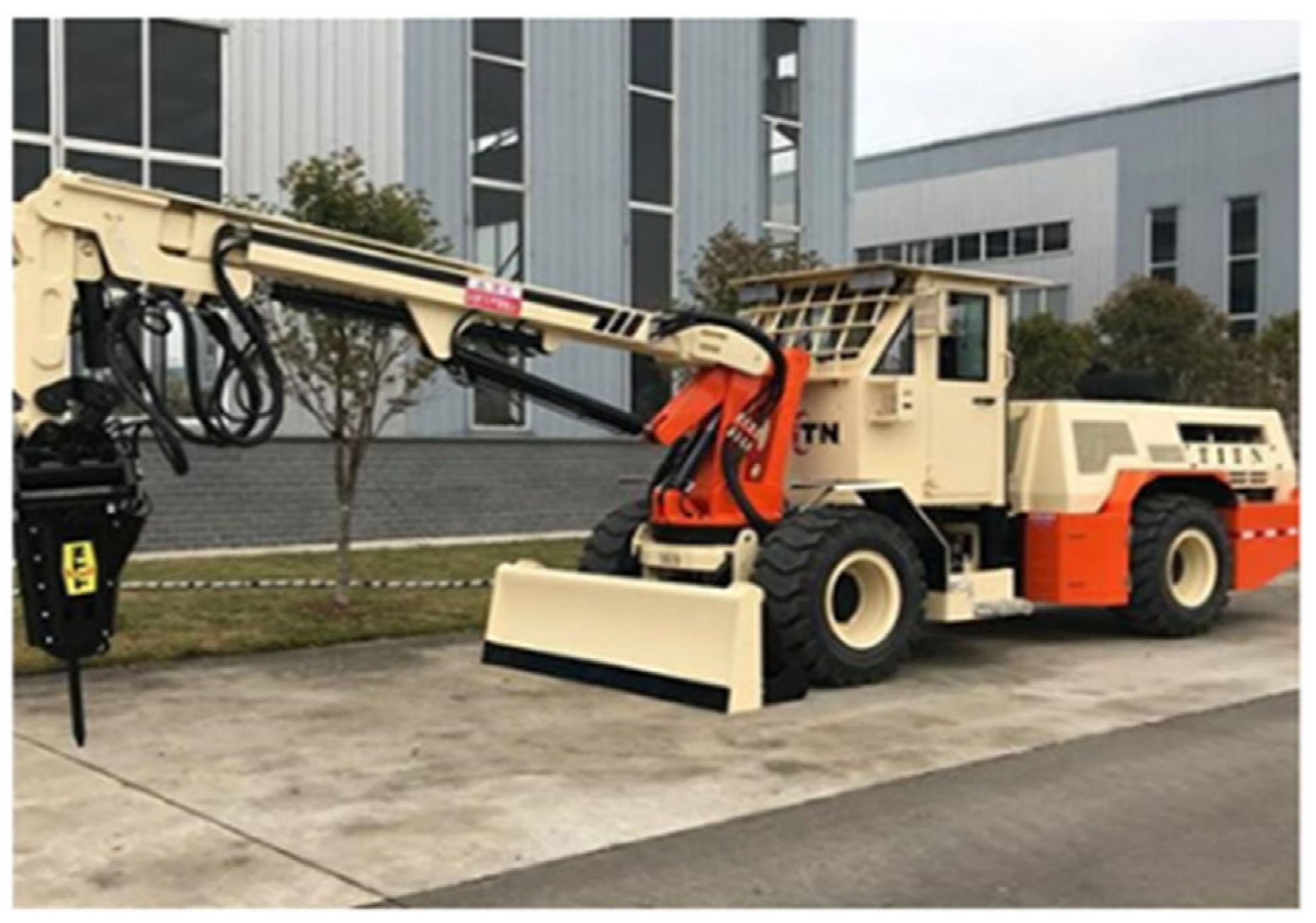
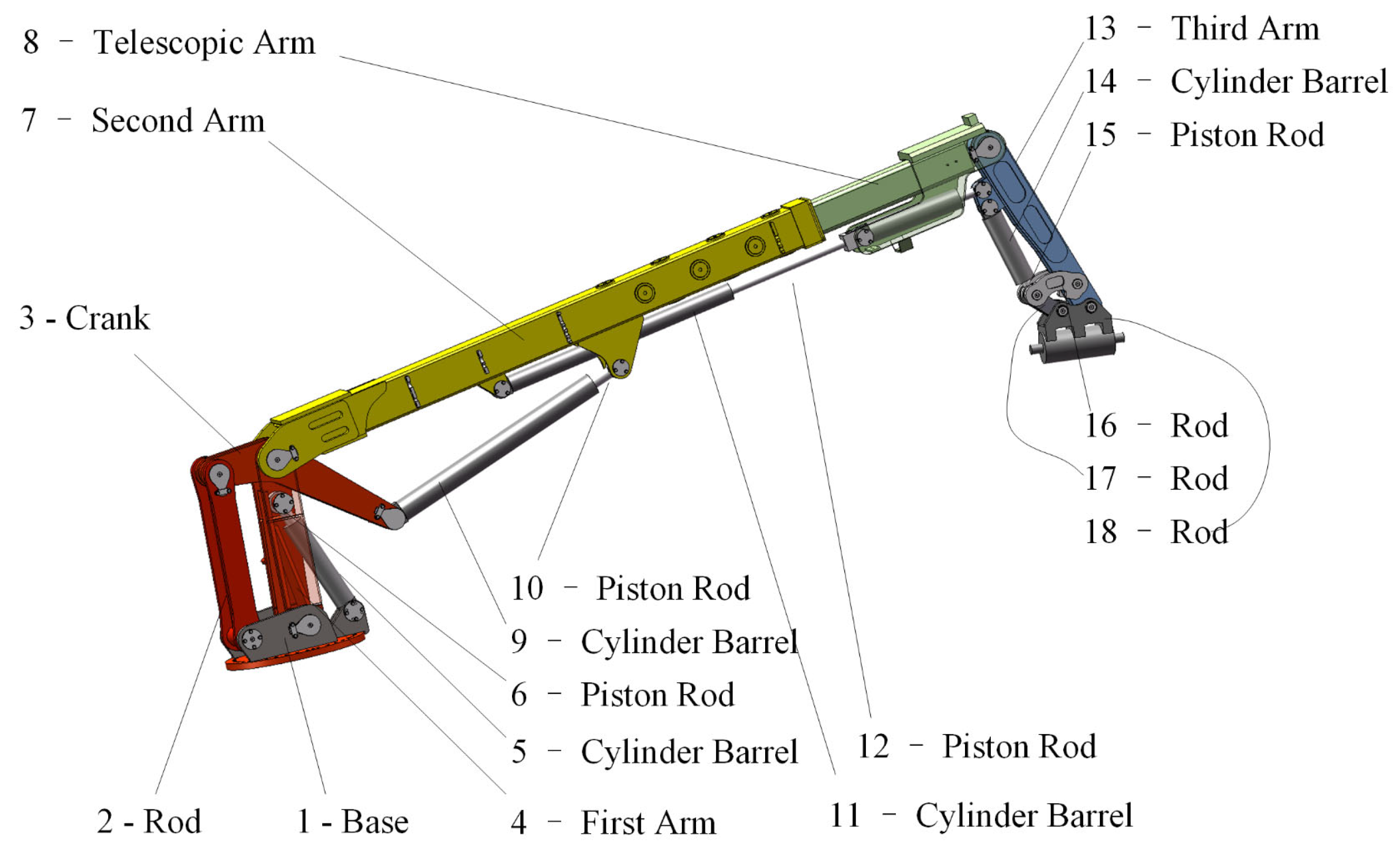
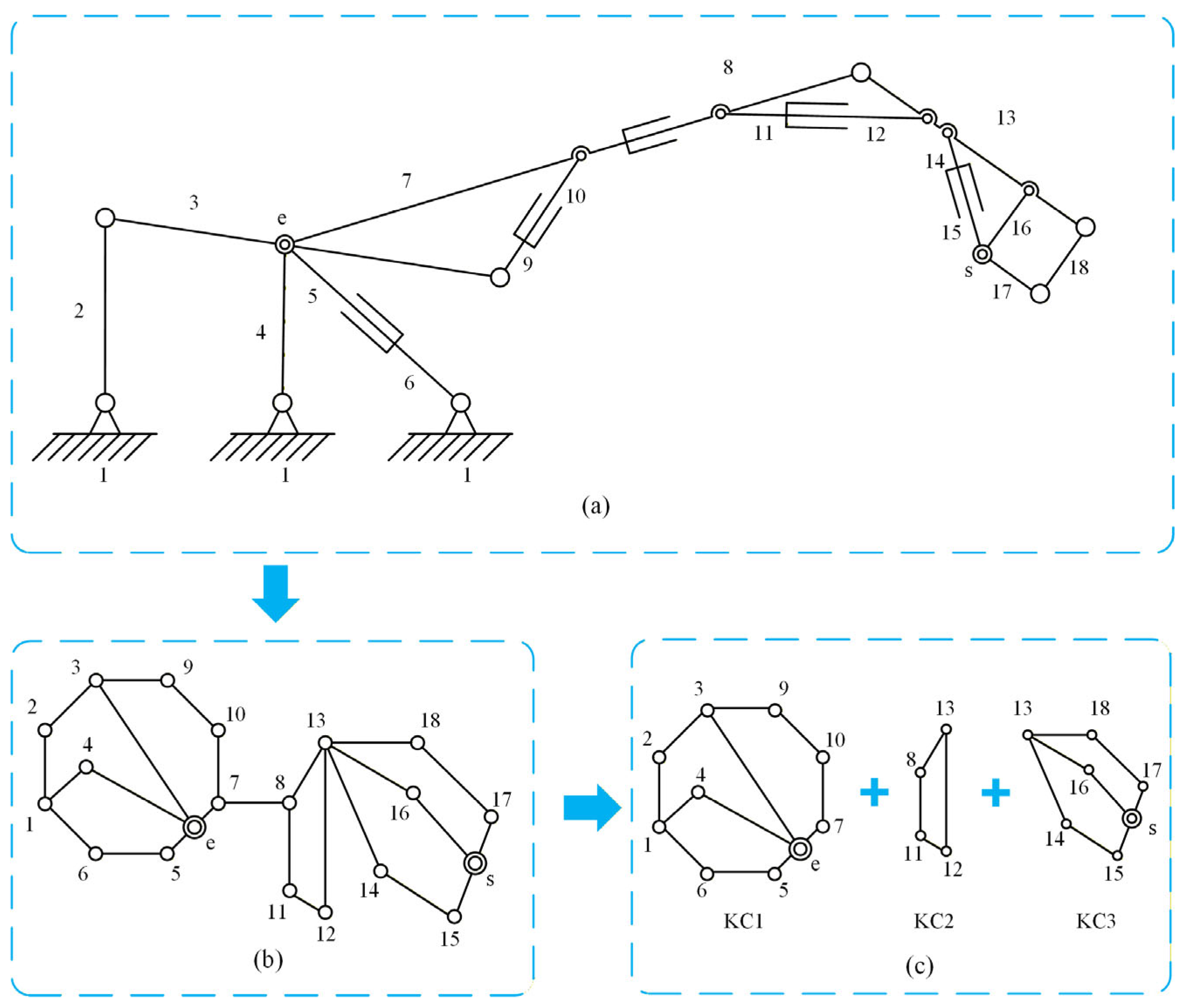
Figure 1 shows a mine scaler manufactured by Hubei Tianteng; its manipulator arm can be modeled as a
N18_
M5 FKC with two MJs (see
Figure 2 and
Figure 3a). In the topological representation, the hydraulic cylinder is equivalently modeled as two binary links (cylinder body and piston rod). The joint between these two links is a prismatic pair; to emphasize that this prismatic pair corresponds to a hydraulic actuator, it is drawn using a cylinder symbol instead of hollow circles.
FKCs can be divided into two basic types: link-fractionation and joint-fractionation. Any FKC is either one of them or their combination. Consider an FKC with N links and M DOF that can be decomposed into two independent kinematic chains, KC1 and KC2, with links and DOF, and links and DOF, respectively.
For link-fractionation FKCs, the following characteristics apply:
For joint-fractionation FKCs, the following characteristics apply:
As an example, the
FKC with two MJs shown in
Figure 3b can be decomposed into three independent subchains: KC1—
N9_
M2, with one MJ; KC2—
N4_
M1; KC3—
N6_
M1, with one MJ. The separation between KC1 and KC2 follows joint-fractionation, whereas that between KC2 and KC3 follows link-fractionation. So, links and DOFs follow the following relationship
Accordingly, the automatic synthesis of FKCs can be completed in two steps:
Step 1: synthesize all required NFKCs according to the links and DOFs of the subchains;
Step 2: assemble the subchains in accordance with the combination rules to complete the FKC synthesis.
2.2. Single Joints and Multiple Joints
According to the joint type, a planar linkage can be classified into single-joint and multiple-joint kinematic chains. For a single-joint chain, its topology can be represented by a conventional single-color topological graph—vertices denote links and edges denote joints. When two links are directly connected by a joint, the corresponding vertices are connected by an edge. By contrast, for multiple-joint chains, using a conventional single-color graph and its associated matrix operations makes further study of structural composition difficult.
There are two mainstream treatments for multiple-joint chains. One is to use a bicolor (two-color) topological graph to represent the topology [
11]. The other, proposed by Ding et al. [
32], is an equivalent transformation: an N-link, M-DOF planar chain with J MJs can be transformed into an (N + J)-link, (M + J)-DOF single-joint chain. In this way, the synthesis of multiple-joint chains is systematically reduced to the synthesis of single-joint chains. This paper adopts the equivalent-transformation approach.
For KC1 and KC3 in
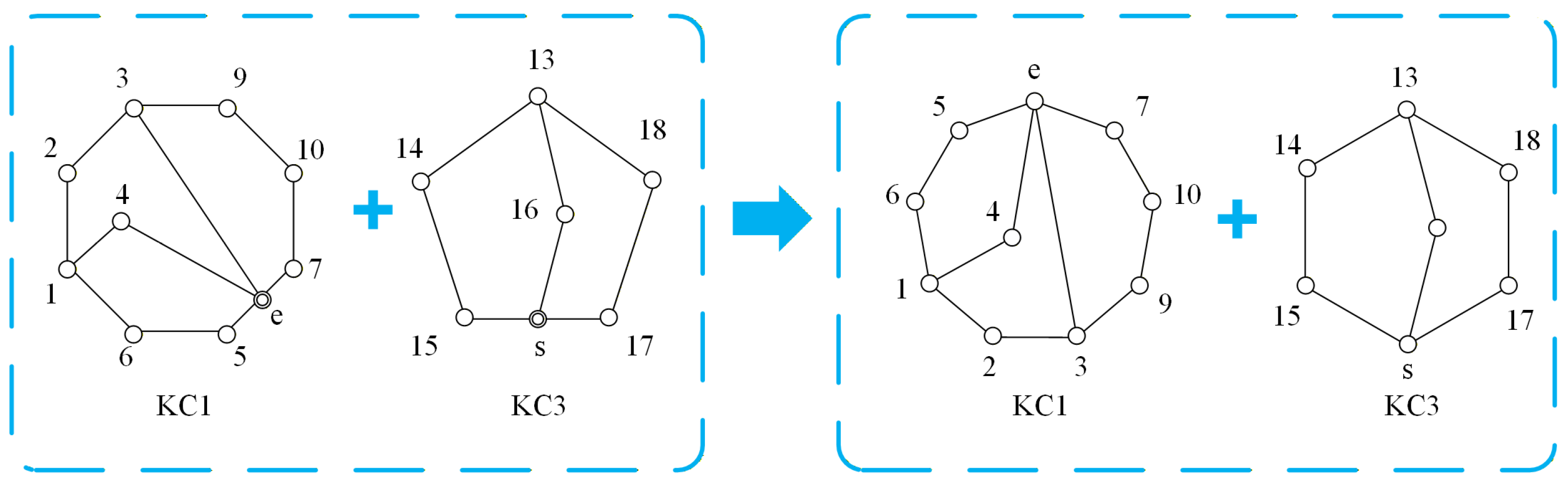
Figure 3c, the transformation yields
N10_
M3 and
N7_
M2 single-joint chains, respectively (see
Figure 4).
2.3. Vertex Symmetry Set and VertexAsymmetry Set
In order to avoid isomorphism during FKC synthesis, the vertex symmetry set (VS) and the vertex asymmetry set (VA) are introduced.
Let
be the topological graph of a planar NFKC. For two vertices
and
, construct
by exchanging the positions and labels of
and
. If
and
are isomorphic, then
and
are said to be topologically symmetric. The
VS set of
is the collection
of all equivalence classes of pairwise symmetric vertices.
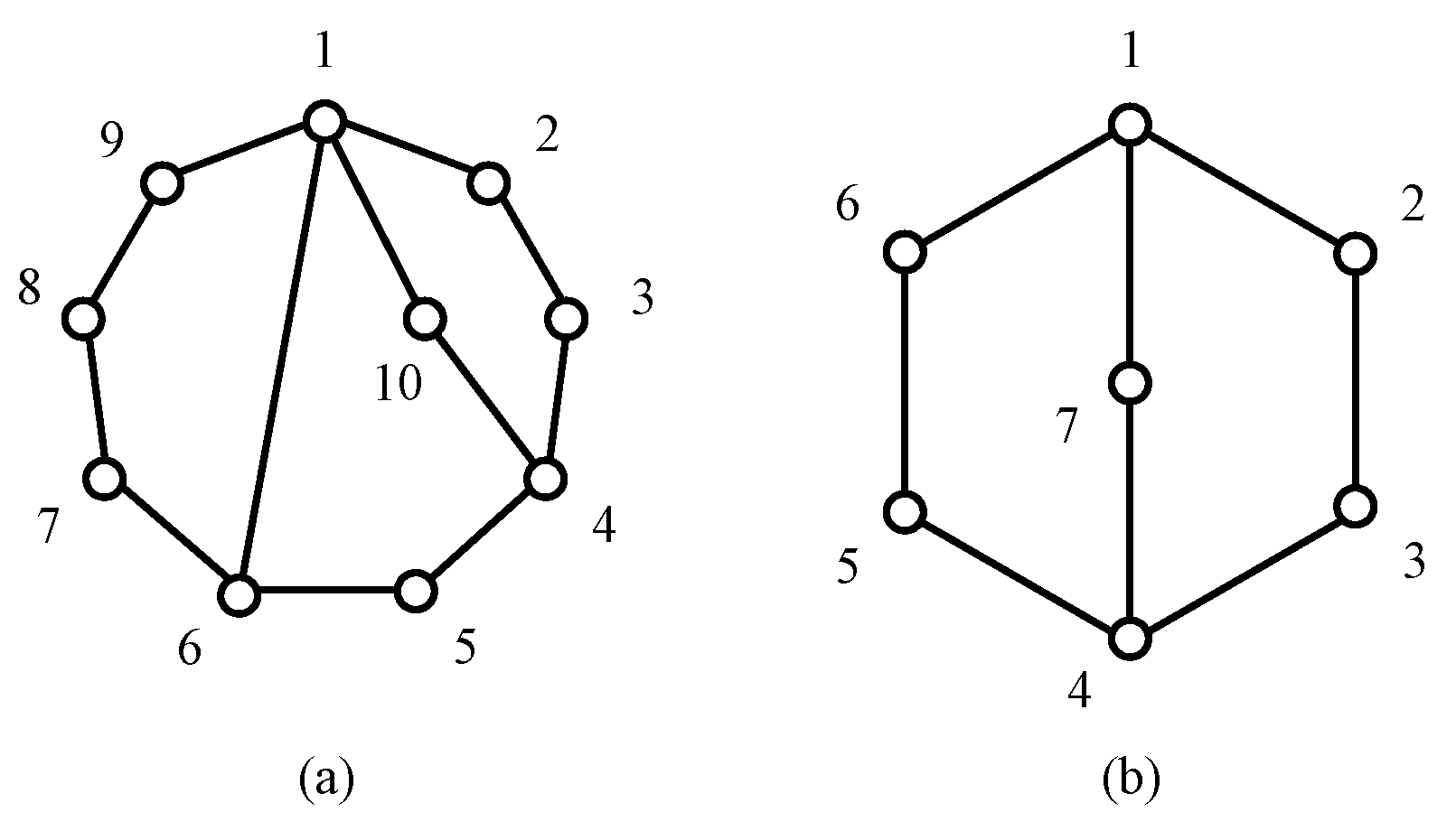
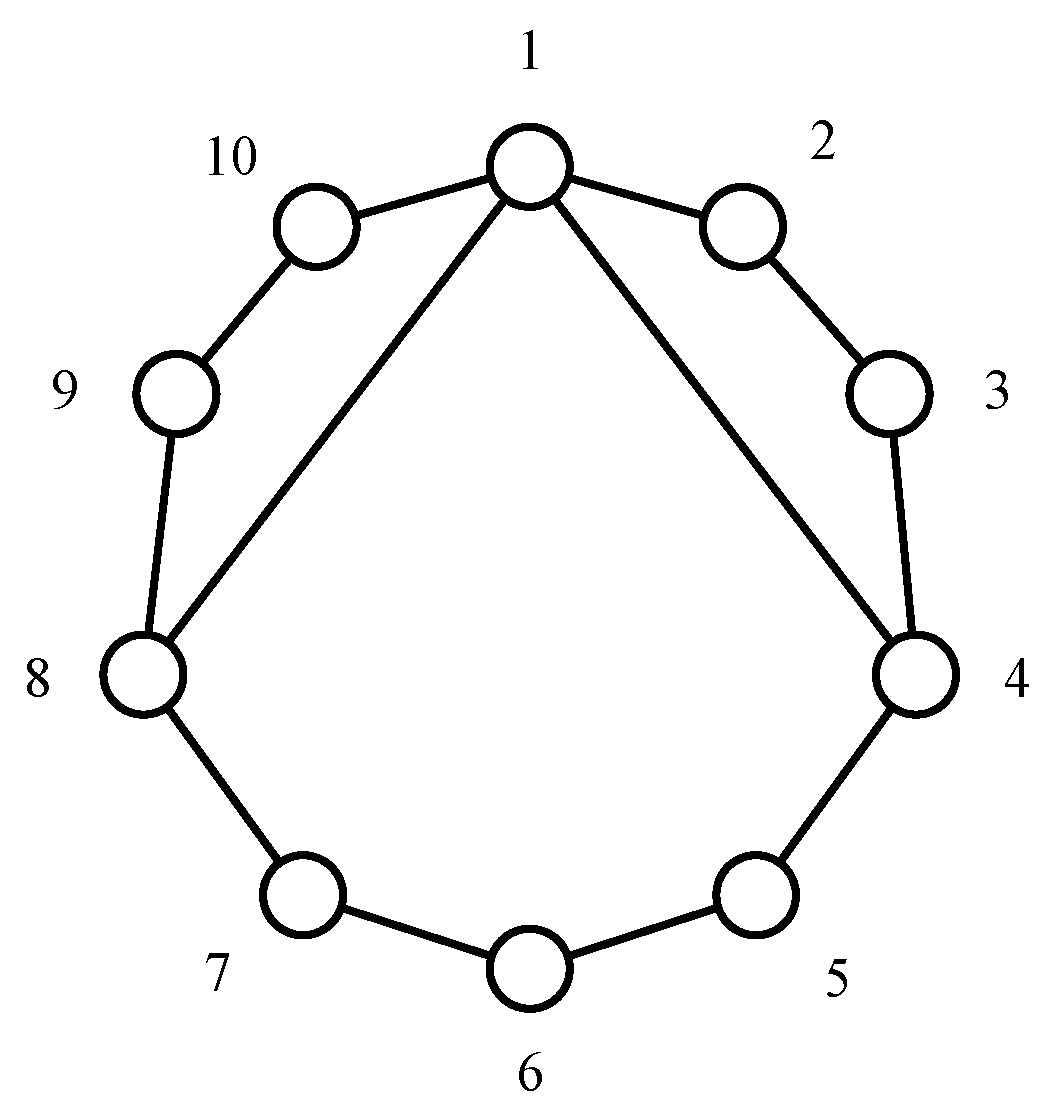
As illustrated by the graph in
Figure 5,
and
are symmetrical, similarly,
and
,
and
,
and
are symmetric. Hence, the
VS of this graph is given in Equation (8).
where
,
,
,
.
From each , select the vertex with the smallest label, the set of these representatives is called the VA. Obviously, any two vertices in VA are asymmetric.
For the graph in
Figure 5, the
VA set is given in Equation (9).
3. Construction of the Subchain Topological Graph Atlas
From
Figure 3c, KC2 is an
N4_
M1 NFKC with a unique configuration. Therefore, to build the subchain topological graph atlas, it suffices to synthesize all feasible configurtions of KC1 and KC3. As described in
Section 2.2, the equivalent-transformation approach that converts multiple-joint KCs into single-joint KCs is adopted. Accordingly, the FKC in
Figure 3a—
N18_
M5 with two MJs—is transformed into a single-joint FKC
N20_
M7; correspondingly, KC1 and KC3 are transformed into single-joint KCs
N10_
M3 and
N7_
M2, respectively. All atlases and screening results reported in
Section 3,
Section 4 and
Section 5 were generated using an in-house software implementation of the proposed workflow.
3.1. Synthesis of Contracted Graphs
This paper adopts the link assortment array (LAA) method from our earlier work to carry out contracted graph synthesis [
33]. The LAA of a kinematic chain is represented by
where
are the numbers of binary, ternary, quaternary links, etc., in that order. If the number is greater than nine, alphabetic letters are used instead in order to avoid multidigital numbers:
represents 10,
represents 11,
represents 12, and so on. For example, the link assortment array
denotes that the number of binary links (
) is 10.
For KC1 and KC3, the LAAs are shown in
Table 2. The contracted graphs synthesized from the four LAAs are given in
Table 3.
3.2. Synthesis of Topological Graphs
A contracted graph is obtained by replacing every binary path in a topological graph with an edge. Consequently, recovering the corresponding topological graph from a contracted graph amounts to inserting an appropriate number of binary vertices along each contracted graph edge. The procedure consists of three steps:
Step 1: Insert a predefined number of binary vertices into the contracted graphs to systematically generate all topological graphs that satisfy the basic synthesis constraints.
Step 2: Perform isomorphism discrimination to eliminate duplicate topological graphs.
Step 3: Conduct rigid-subchain detection to further exclude topological graphs lacking feasible mobility, thereby obtaining a complete topological atlas.
3.2.1. Rules for Binary Vertex Insertion
Suppose that a contracted graph contains n vertices, and its edge set is denoted as . The number of binary vertices inserted on edge is represented by , and the collection of all insertion numbers is denoted as . The process of obtaining a topological graph from a contracted graph can thus be regarded as sequentially inserting binary vertices along its edges. This process must satisfy the following rules:
Rule 1: The total number of inserted binary vertices must equal the difference between the links of the mechanism and the number of vertices in the contracted graph.
Rule 2: The number of binary vertices inserted on each edge cannot exceed its prescribed upper limit.
Rule 3: If the multiple edges between two vertices is denoted as
, the numbers of binary vertices inserted on these edges must satisfy the following constraints:
By combing Equations (11)–(13), equation set (14) can be obtained.
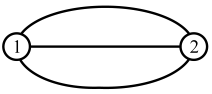
In particular, for the contracted graph consisting of only two vertices, as shown in
Table 3, Rule 3 must be modified according to the parity of the number of multiple edges. Two cases can be distinguished:
When the number of multiple edges is even, they should be divided into two groups, and the inserted binary vertices in each group must respectively satisfy the constraints of Rule 3.
When the number of multiple edges is odd, the
-th multiple edge should be selected as the middle edge, while the remaining edges are divided into two groups, and the inserted binary vertices in each group must respectively satisfy the constraints of Rule 3.
Accordingly, for the contracted graph corresponding to the LAA
in
Table 3, equation set (4) can be rewritten in the form of equation set (17).
By solving equation set (17), all integer solutions that satisfy the constraints can be obtained, and the corresponding adjacency matrices of the kinematic chains can be generated.
3.2.2. Isomorphism Discrimination
During the automatic synthesis process, a two-level isomorphism discrimination procedure is adopted to ensure the uniqueness and validity of the generated topological graphs. In the first stage, following the characteristic-code method proposed by Ding et al. [
11], candidate topological graphs are encoded based on their adjacency matrices and main-loop features, enabling rapid preliminary screening. This method offers advantages of low computational cost and high discrimination efficiency, thereby reducing redundancy in large-scale atlas generation. However, it has been observed that relying solely on the characteristic code entails certain limitations. For example, in the
N10_
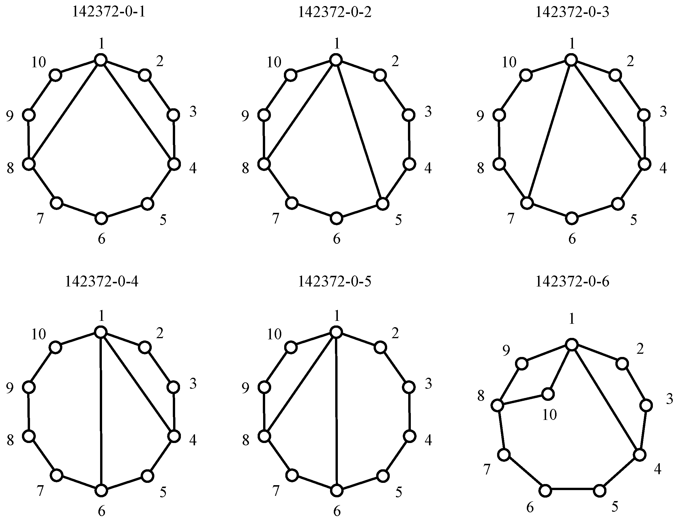
M3_721 topological atlas, some symmetric graphs cannot be completely eliminated (
Figure 6). Specifically, graphs 142372-0-2 and 142372-0-3 are in fact isomorphic, but their characteristic codes are A-1518 and A-1417, respectively, making accurate discrimination difficult when only the characteristic code is applied.
To overcome this limitation, the Weisfeiler–Lehman graph hashing (WL-hash) algorithm [
34,
35] is introduced as a secondary discrimination tool. By iteratively updating and compressing neighborhood labels, WL-hash can effectively distinguish graph structures by exhibiting strong symmetries. The combined strategy of preliminary screening by characteristic codes followed by strict discrimination via WL-hash achieves a balanced trade-off between computational efficiency and discrimination accuracy, thereby overcoming the limitations of a single method and ensuring the consistency and uniqueness of the final synthesis results.
3.2.3. Rigid-Subchain Detection
For a given planar kinematic chain, if there exists a closed loop subchain whose degrees of freedom () are less than or equal to zero, all links within this subchain cannot achieve relative motion and can therefore be solidified into a single rigid body. Such closed loop subchains are defined as rigid subchains. During planar kinematic chain synthesis, any structure containing rigid subchains must be eliminated.
3.2.4. Synthesis Results
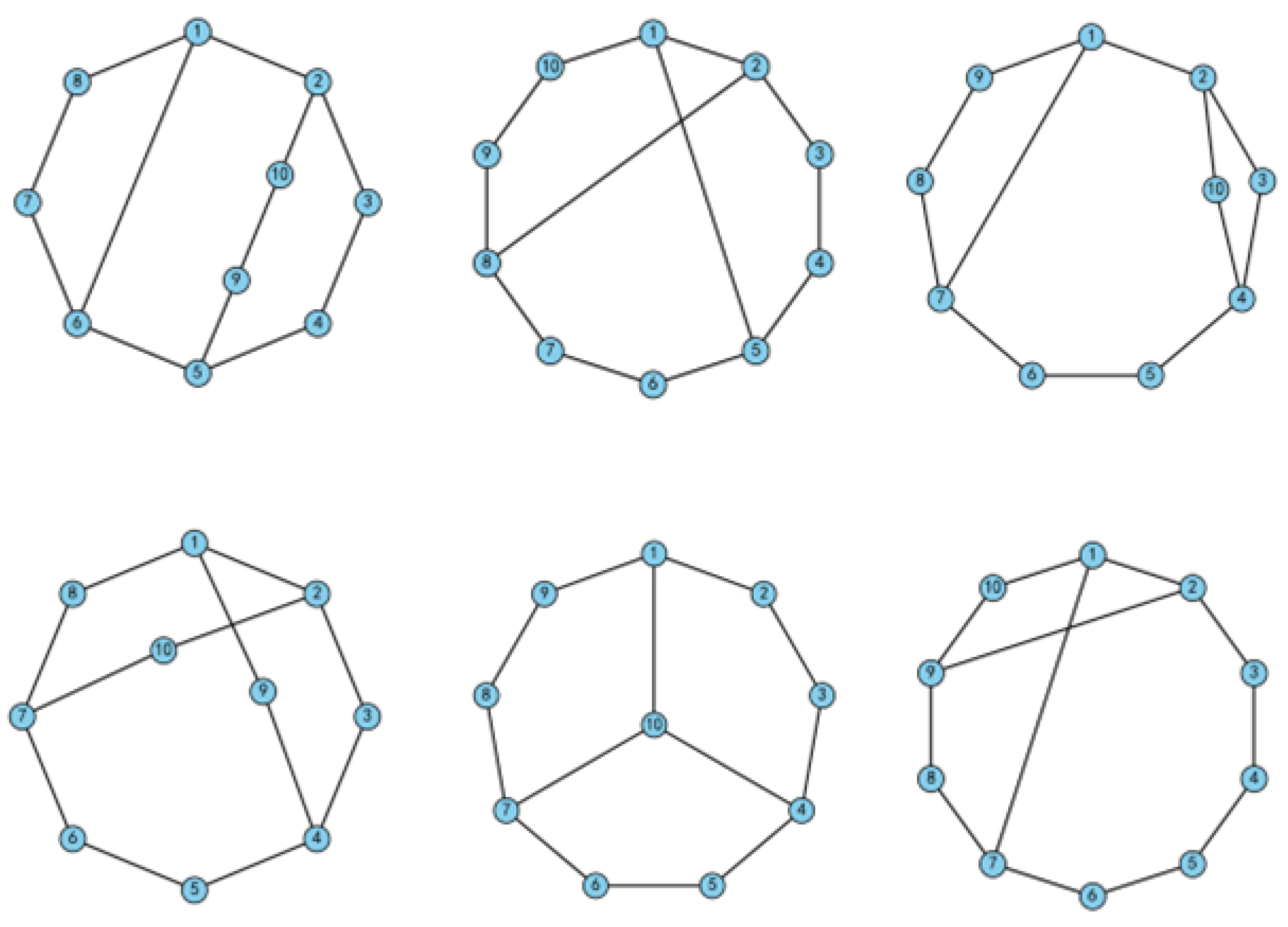
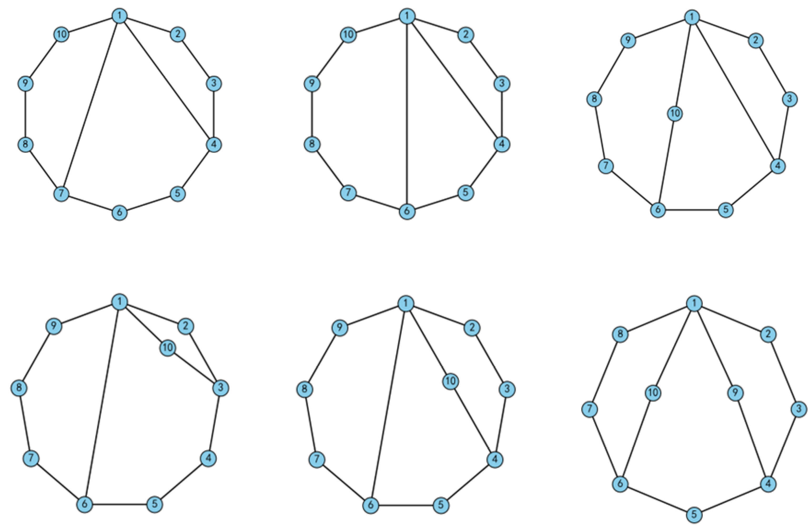
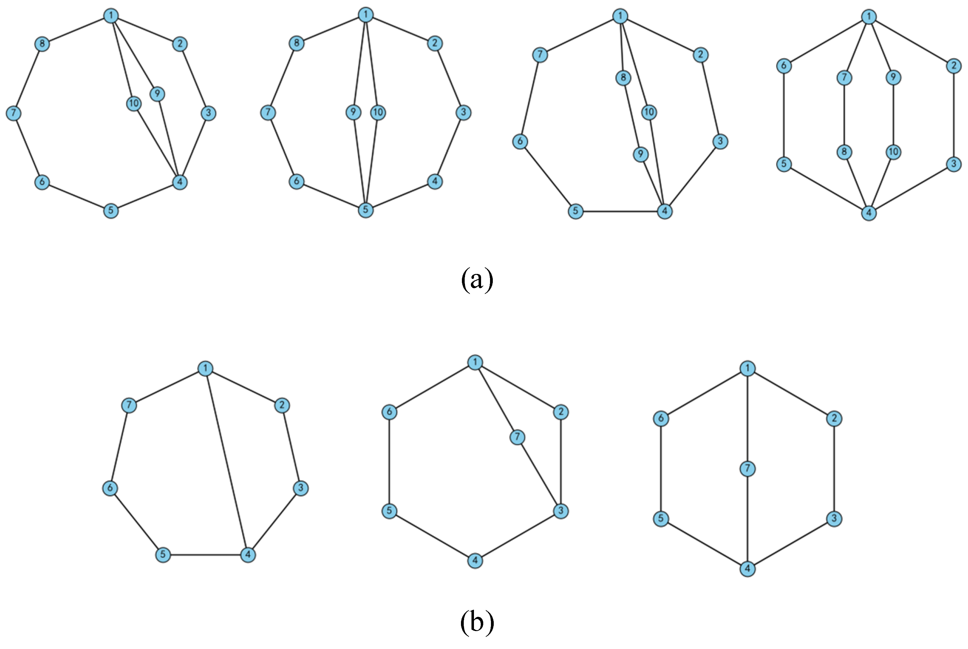
Based on the above procedure, the full set of topological graphs corresponding to any given contracted graph system can be generated. In total, seventy-four topological graphs were obtained for KC1 and three for KC3, as shown in
Figure 7,
Figure 8 and
Figure 9. The synthesis result of the KC1 graph atlas is shown in
Table 4.
4. Topological Graph Atlas of N20_M7 Simple-Joint FKC
For readability, a high-level overview of how the design space is progressively reduced from subchain atlas construction to the final non-isomorphic FKC atlas is provided.
Table 5 summarizes the major operations and intermediate sets, while
Section 4.1,
Section 4.2,
Section 4.3 and
Section 4.4 present the detailed combination rules and the AB/BA construction procedure.
4.1. Rules of Combination
As described in
Section 2, the target mechanism is an FKC
with two MJs. It can be decomposed into three non-fractionated subchains (KC1, KC2, KC3; see
Figure 3c), where the KC1 and KC2 interface follows joint-fractionation (A-mode) and the KC2 and KC3 interface follows link-fractionation (B-mode). In principle, the three subchains admit four combination classes: AA, AB, BA, and BB. However, due to conservation of link count and DOF under the chosen fractionation, AA yields
N19_
M6 and BB yields
N21_
M8, both deviating from the target
N20_
M7. Hence, this study focuses on the AB and BA modes.
To avoid isomorphism blow-up during synthesis, interfaces are enumerated over the VA sets of each subchain rather than over all vertices. For example, in the scheme of
Figure 10 with
and
, combining KC1 and KC3 alone gives
non-isomorphic results [
13]. In the three-subchain case, however, the full enumeration
may contain globally isomorphic graphs that differ only in interface placement. Therefore, after completing all AB and BA combinations, we perform isomorphism identification on the
candidate topological graph atlas, yielding a deduplicated atlas as the final result.
4.2. Isomorphism Discrimination for FKC
Research on isomorphism identification tailored to FKCs remains limited. In 2024, Huang et al. [
32] proposed a procedure for 2-DOF FKCs with a single MJ under two-subchain combinations. However, the method relies on specific premises—such as perimeter-loop localization with anchor setting and a fixed priority between the two subchains—and does not scale to the
N20_
M7 case with three-subchain combinations or to higher-order instances. In other words, a general framework for isomorphism identification with up to three subchains has not been systematically reported.
To this end, a WL-hash -based, general-purpose workflow is proposed. Vertex initial coloring encodes vertex type (simple joint or MJ) and multi-edge information, followed by Weisfeiler–Lehman color refinement to obtain a stable hash for high-throughput deduplication. Recognizing the theoretical indistinguishability limits of 1-WL on a few graph families, hash collisions are resolved via lightweight secondary checks (global degree sequence, consistent multi-edge counts, consistency of main-loop or maximum-loop sets, and multi-set consistency of interface vertices), ensuring zero false positives. The workflow is independent of perimeter-loop and anchor assumptions, parallelizable, and particularly sensitive to global isomorphism induced by permutations of subchain interface locations—well suited to the large candidate sets generated under AB and BA enumeration.
Isomorphism discrimination procedure:
Step 1. For each global FKC obtained by combining KC1, KC2, KC3, computes and stores its WL-hash.
Step 2. Bucket graphs by hash value and perform secondary checks within each bucket; when isomorphism is detected, keep only one representative. This yields a deduplicated candidate topological graph atlas.
The method has near-linear amortized complexity per refinement round, enabling fast, batched de-isomorphism for large three-subchain combinations. Compared with the specialized scheme in reference [
32] for 2-DOF FKCs with a single MJ under two-subchain combinations, the proposed approach is not constrained by DOF, the number of subchains, or the number of MJs, and therefore offers greater generality and scalability.
4.3. Combination of AB Type
The AB type denotes joint-fractionation (A) at the interface of KC1 and KC2 and link-fractionation (B) at the interface of KC2 and KC3. Leveraging the KC1 and KC3 topological graph atlases obtained in
Section 3, interface candidates are enumerated over the VA sets of each subchain, and consistency constraints—DOF conservation, interface–vertex degree matching, and multi-edge preservation—are imposed to systematically generate all AB-mode candidate FKCs. The procedure is as follows:
Step 1. For the -th topology from the KC1 atlas, read the representatives in and connect them, one by one, to the A-side interface of KC2 to form intermediate structures.
Step 2. For the -th topology from the KC3 atlas, read the representatives in and connect them, one by one, to the B-side interface of KC2 for each intermediate structure from Step 1; compute and store the WL-hash for every resulting global FKC.
Step 3. Traverse all pairs to complete enumeration.
Step 4. Bucket by WL-hash and deduplicate; within each bucket, perform lightweight consistency checks and keep a single representative, yielding a deduplicated candidate topological graph atlas.
Following this workflow, the AB-mode
N20_
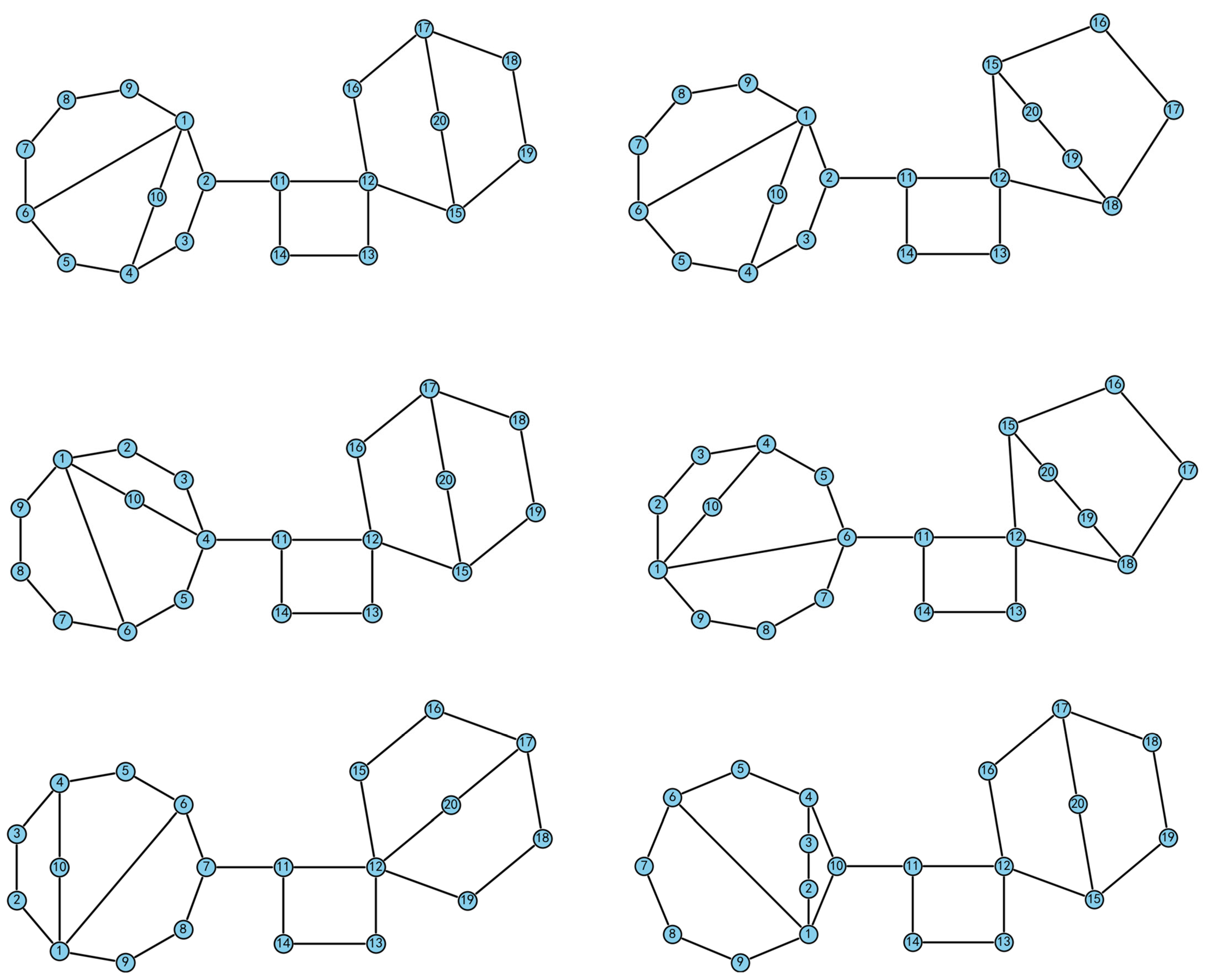
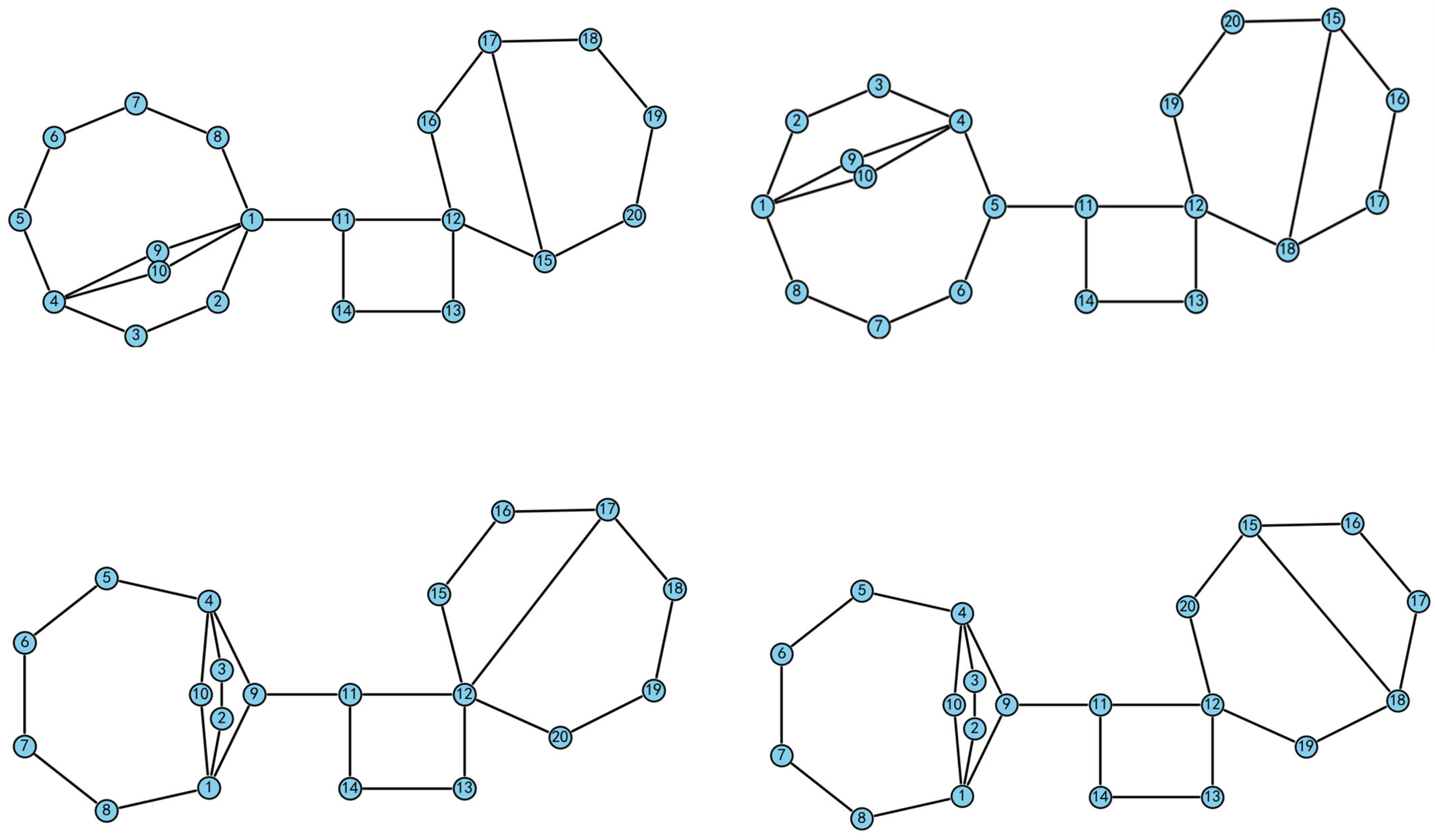
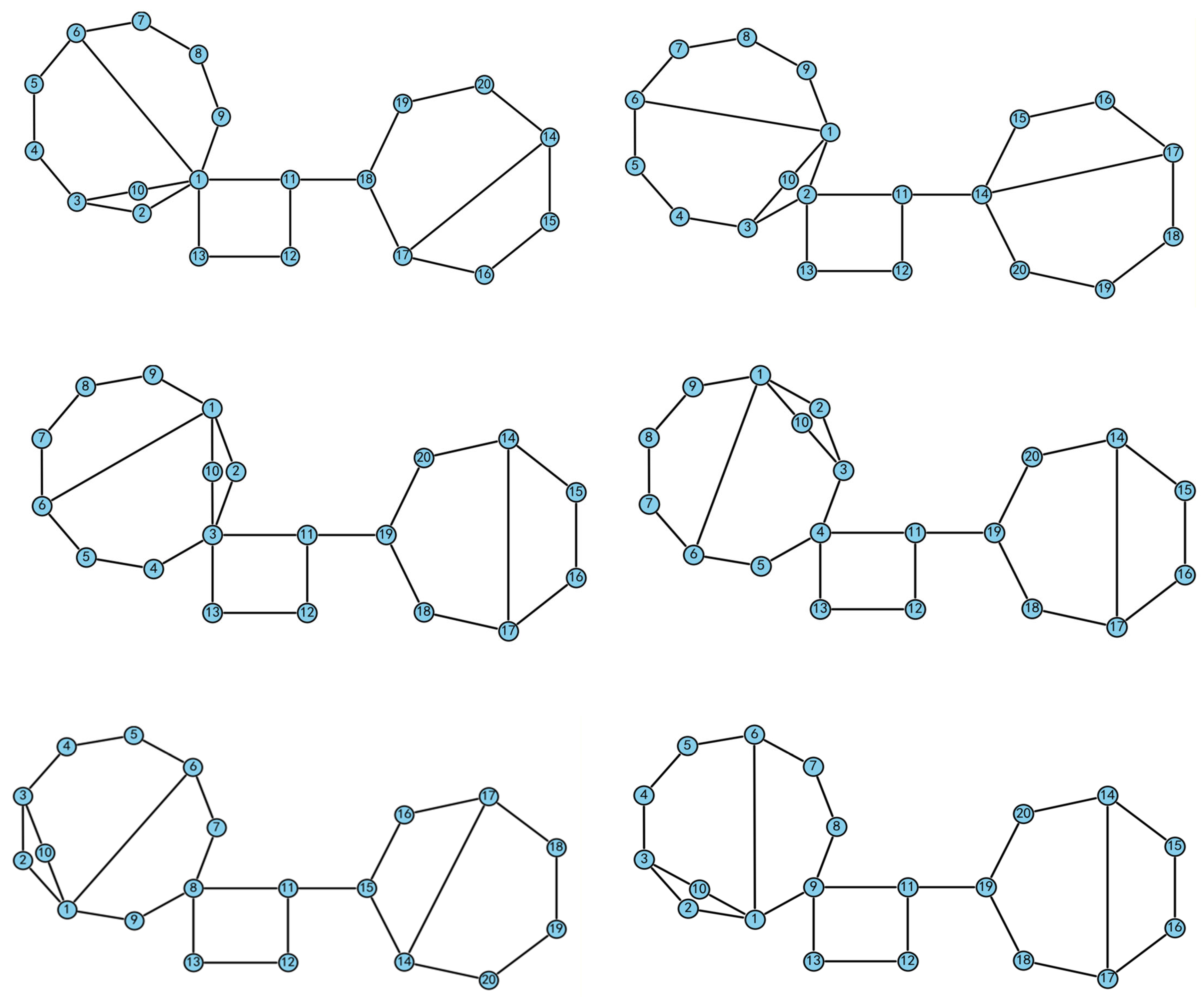
M7 deduplicated candidate atlas contains 5022 topological graphs. Representative FKCs of the atlas are shown in
Figure 11 and
Figure 12, the complete atlases are provided in the
Supplementary Materials S1 (PDF).
4.4. Combination of BA Type
The BA type denotes link-fractionation (B) at the interface of KC1 and KC2 and joint-fractionation (A) at the interface of KC2 and KC3. Building on the KC1 and KC3 topological graph atlases from
Section 3, interface candidates are enumerated over each subchain’s VA set, and consistency constraints—DOF conservation, interface–vertex degree matching, and multi-edge preservation—are imposed to systematically generate all BA-mode candidate FKCs. The procedure is as follows:
Step 1. For the -th topology in the KC1 atlas, read the representatives in and connect them, one by one, to the B-side interface of KC2 to form intermediate structures.
Step 2. For the -th topology in the KC3 atlas, read the representatives in and connect them, one by one, to the A-side interface of KC2 for each intermediate structure from Step 1; compute and store the WL-hash for every resulting global FKC.
Step 3. Traverse all pairs to complete enumeration.
Step 4. Bucket by WL-hash and deduplicate; within each bucket, perform lightweight consistency checks and keep a single representative, yielding a deduplicated candidate topological graph atlas.
Following the AB/BA combination and de-isomorphism workflow above, the topological graph atlas for the
N20_
M7 FKC composed of KC1 (
N10_
M3), KC2 (
N4_
M1), and KC3 (
N7_
M2) is constructed. Isomorphic duplicates were removed using WL-hash plus lightweight secondary checks.
Table 6 summarizes the post-deduplication counts for the AB and BA combinations.
5. Creative Design Based on the Topological Graph Atlas
In this section, the application-oriented screening stage of the proposed workflow is introduced. The screening procedure has been implemented in Python (v3.12), and the synthesized candidates and screening results are stored in JSON files to support traceability and reproducibility. It should be noted that the screening criteria are formulated at the topological and kinematic levels; therefore, performance metrics such as force transmission capability and stiffness are not explicitly evaluated at this stage, because they depend on geometric dimensions, material properties, and actuator parameters that are not defined during atlas construction. These aspects are intended to be addressed in subsequent dimensional synthesis and engineering verification.
In conventional mine-scaler manipulator design, feasible configurations are commonly generated through experience-driven conceptual design and iterative refinement. Topology exploration is largely performed manually, and only a limited portion of the design space can be examined. In contrast, the proposed workflow enables systematic enumeration, deduplication, and rule-based screening of candidate topologies, while maintaining a consistent and traceable record of intermediate and final results. As a result, manual trial-and-error in topology exploration can be reduced, and configuration exploration can be conducted in a more comprehensive and repeatable manner.
5.1. Design Constraints
Once the topological graph atlas is established, creative design for a given task reduces to selecting suitable topologies from the complete atlas under the proposed constraints. The constraints are divided into structural and functional; different combinations lead to different candidate sets and final schemes. The constraints for the mine scaler manipulator arm are summarized below.
- (1)
Structural constraints
S1: Rigid-subchain check after reverting to MJs.
The target
N20_
M7 FKC is derived from
N18_
M5 FKC with two MJs via equivalent transformation, one MJ is in KC1, the other is in KC3. Therefore, KC1 and KC3 must contain at least one multi-degree vertex to support the equivalence. But not every multi-degree vertex can be validly reverted to an MJ [
32]. If a subchain contains only four vertices, converting its multi-degree vertex into an MJ will produce a rigid subchain. Accordingly, a post-conversion rigidity test must be performed for each subchain; any configuration that yields a rigid subchain must be discarded.
S2: Consistency of fractionation modes.
Within the required workspace, minimize the overall envelope to fit narrow mine drifts. A telescopic arm is used and is typically arranged on the first arm segment (see
Figure 3a, the joint between links seven and eight). Therefore, KC1 and KC2 are connected by a hydraulic cylinder and are therefore defined as A-mode. Accordingly, to satisfy scale conservation and assembly constraints, KC2 and KC3 adopt B-mode, feasible solutions are screened only from the AB-mode topological graph atlas.
S3: Uniqueness of KC2 architecture.
KC2 contains one hydraulic cylinder. Its four vertices form two adjacent pairs: one adjacent pair serves as interfaces to KC1 and KC3, and the other adjacent pair are the two ends of the cylinder. Hence the layout of KC2 is unique.
- (2)
Functional constraints
F1: Actuator layout and redundancy.
The global configuration uses five hydraulic cylinders (KC1 × 2, KC2 × 1, KC3 × 1, and one between KC1 and KC2). When KC1 contains only two binary-vertex chains, it triggers redundancy checks:
F1.1: the two cylinders must not be connected in series.
F1.2: the two cylinders must not be simultaneously anchored to the same vertex pair within the same independent loop.
F2 Functional localization and connectivity index.
During configuration synthesis, the connectivity index is used to locate the base and end effector (EE). For simplicity, global localization is mapped to subchains: the FKC base is taken from the KC1 base; the interface of KC1 and KC2 is treated as the EE of KC1; the interface of KC2 and KC3 is treated as the base of KC3; and the FKC EE is taken from the EE of KC3. For the mine scaler manipulator arm, the EE has a single-DOF pitching motion in the longitudinal plane. After transforming the N18_M5 FKC with two MJs into its single-joint equivalent N20_M7 FKC, the mechanism gains two additional DOFs overall (with KC1 and KC3 each gaining one). Correspondingly, the required base/EE connectivity thresholds increase from 1 to reflect the added mobility, KC1 and KC2 are connected by joint-fractionation (A), with the interface realized by a hydraulic cylinder; accordingly, the connectivity index for KC1 must be increased by one. Hence, for KC1 and for KC3 are adopted as the screening criteria for base/EE placement.
These screening criteria are expected to influence downstream performance in several ways. The connectivity-index constraints strengthen kinematic coupling between the base, EE, and key interfaces, improving controllability by enabling effective propagation of actuator inputs and reducing weakly connected substructures that are sensitive to disturbances. The actuator-layout and redundancy rules (F1.1–F1.2) remove candidates prone to over-constraint or ineffective actuation, reducing internal load circulation and improving practical load-bearing behavior. Overall, these rules serve as topology-level pre-screening and help exclude designs with poor reachable motion or undesirable actuation interactions.
5.2. Results of Creative Design
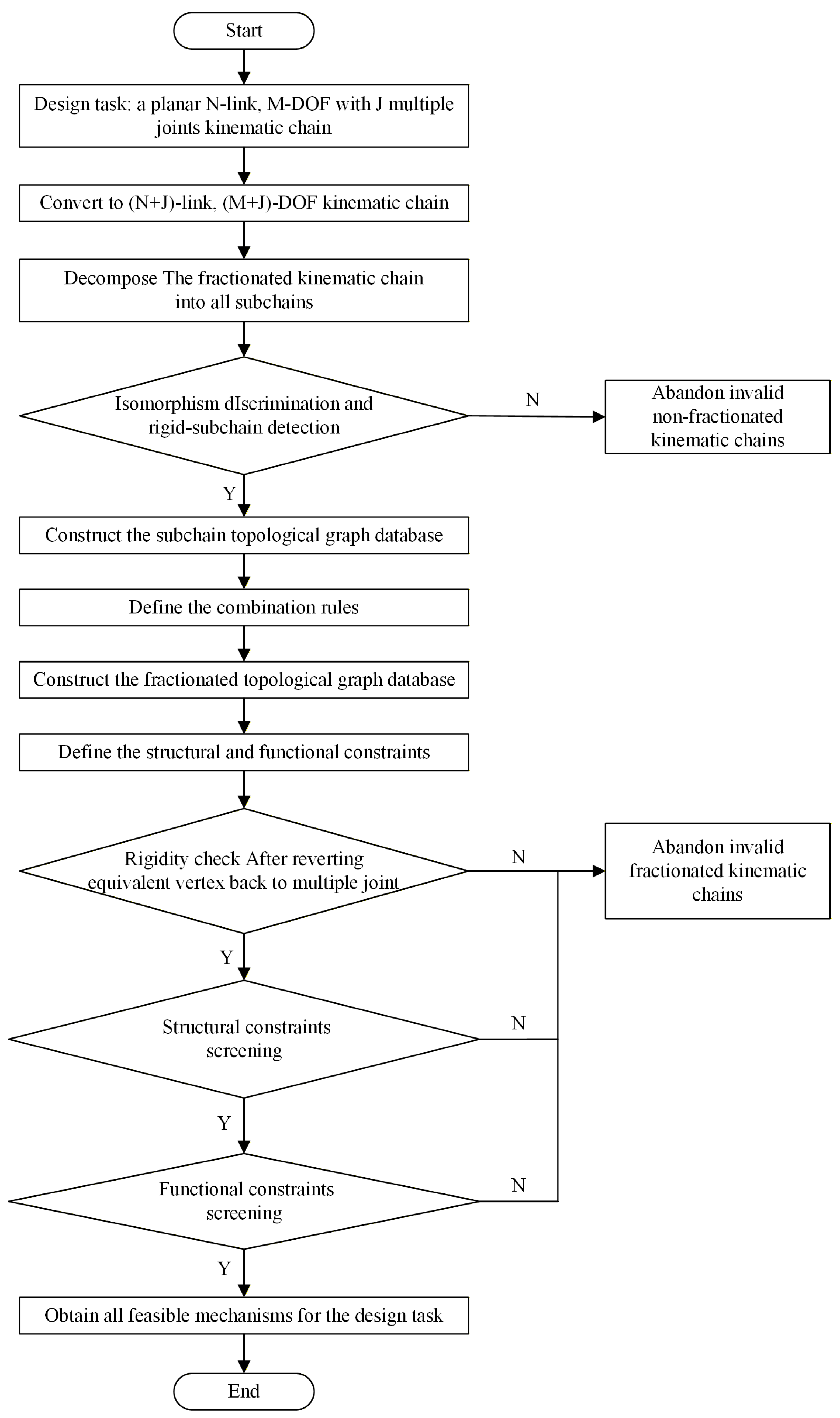
To improve screening efficiency, a rigidity check is first performed after reverting single-joint equivalents back to multiple-joint vertices. Next, the structural constraint screening is conducted. Then, candidate base and EE sets are then determined, and feasible base/EE pairs are identified using the connectivity matrix. Finally, actuator redundancy rules are applied to obtain the final set of solutions. The workflow is illustrated in
Figure 15. As N and DOF increase, the candidate set expands rapidly, and the repeated isomorphism discrimination during subchain/fractionated database construction becomes the primary bottleneck.
Under the structural constraints S1–S3 and functional constraints F1–F2 (including F1.1/F1.2) in
Section 5.1, the AB deduplicated candidate sets were filtered as follows:
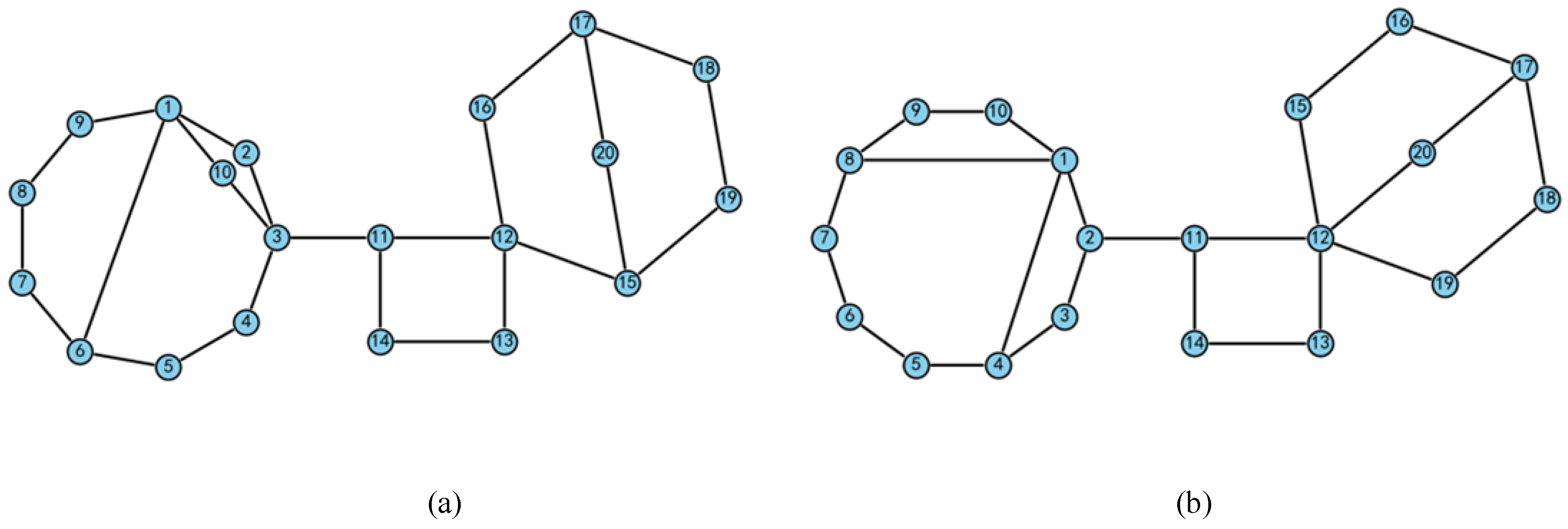
Step 1. For the AB mode atlas, determine the equivalent multiple-joint vertex in KC1 and in KC3. Check whether the independent loop containing each equivalent vertex includes a four-vertex loop. If there exists a vertex that can be transformed into an MJ, proceed to Step 2; otherwise discard the graph.
Example: In
Figure 16a, the candidate vertices in KC1 is
. There is a four-vertex cycle
including
and
, so these two vertices could not transform into MJs. However, independent loops containing vertex
are
and
, both loops have more than four vertices, therefore, this graph can be retained. In
Figure 16b, the candidate vertices in KC1 are
. There is a four-vertex cycle
including
and
, a four-vertex cycle
including
, S1 is triggered and the topology is discarded.
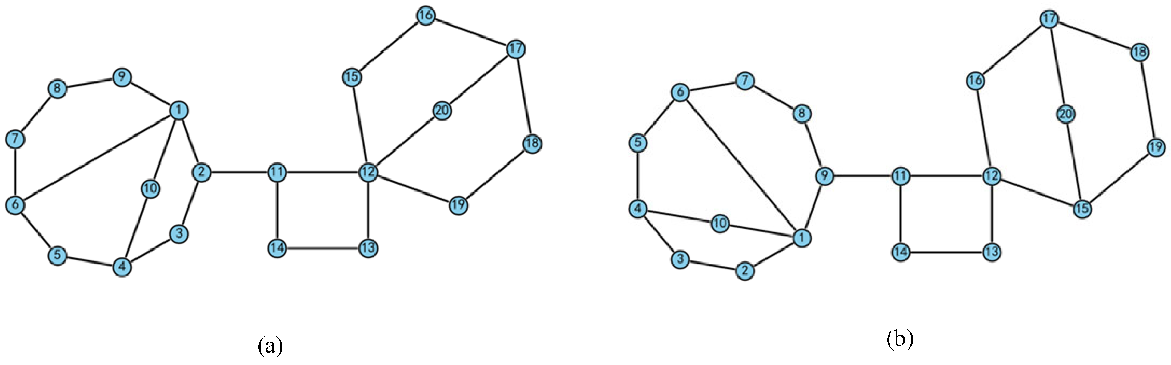
Step 2. Determine the candidate sets for base and EE. The base candidates are all multi-degree vertices in KC1 except ; the EE candidates are all binary vertices in KC3. Retrieve the corresponding connectivity matrix and interface vertices of the three subchains: the interface of KC1 and KC2 is and the interface of KC2 and KC3 is . Check the connectivity criteria and . If both are satisfied, the VS set of this topological graph is then used to verify the base vertices in the KC1 and KC3 subchains, perform isomorphism discrimination, and eliminate symmetric base vertices. After eliminating isomorphic cases, the process proceeds to Step 4; if no base–EE vertex pair satisfies the connectivity criterion, discard the topological graph and set k = k + 1.
Example: In
Figure 17a, the base candidate
in KC1 has connectivity 2 to the interface
, which fails the criterion, and the topology is discarded. In
Figure 17b, the base
in KC3 has connectivity 1 to the EE candidate
, which fails the criterion, and the topology is discarded.
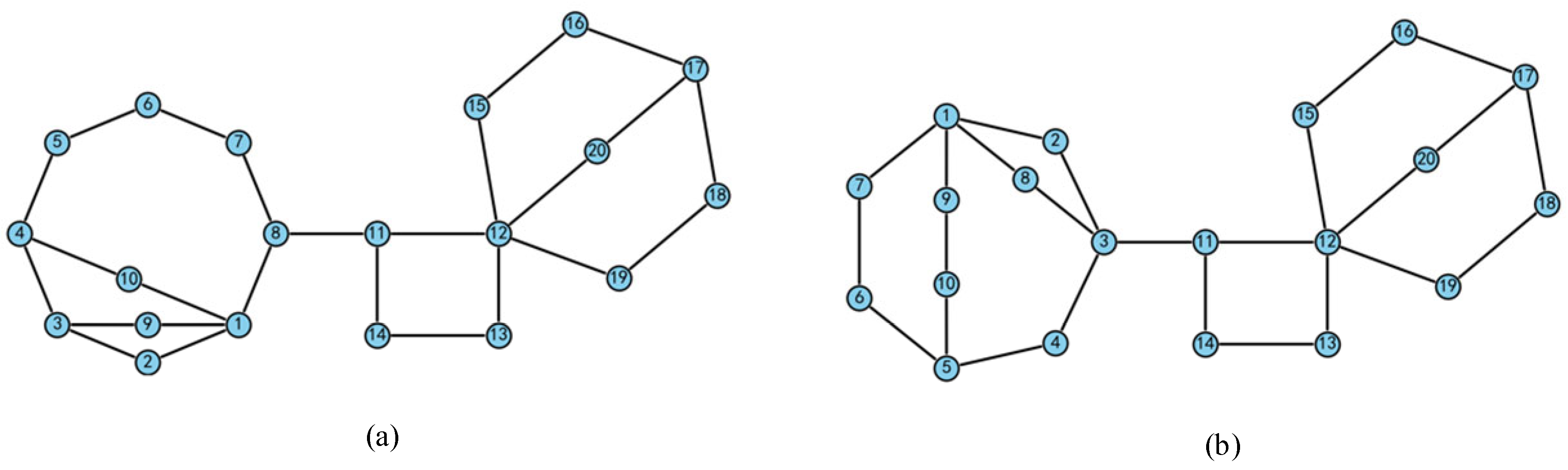
Step 3: Evaluate actuator placement in KC1 for redundancy. If no redundancy is detected (both F1.1 and F1.2), proceed to Step 5; otherwise discard and set k = k + 1.
Example: In
Figure 18a, the cylinder layout in KC1 admits only one option:
and
; they are in series, triggering F1.1, and must be discarded. In
Figure 18b, the cylinder layout in KC1 admits only one option:
and
, both of them connect
and
, which triggers F1.2, and must be discarded.
Step 4: Accepts the -th topology as feasible configuration, set k = k + 1.
Following the above procedure, the constructed FKC topological graph atlas is screened under the structural and functional constraints in
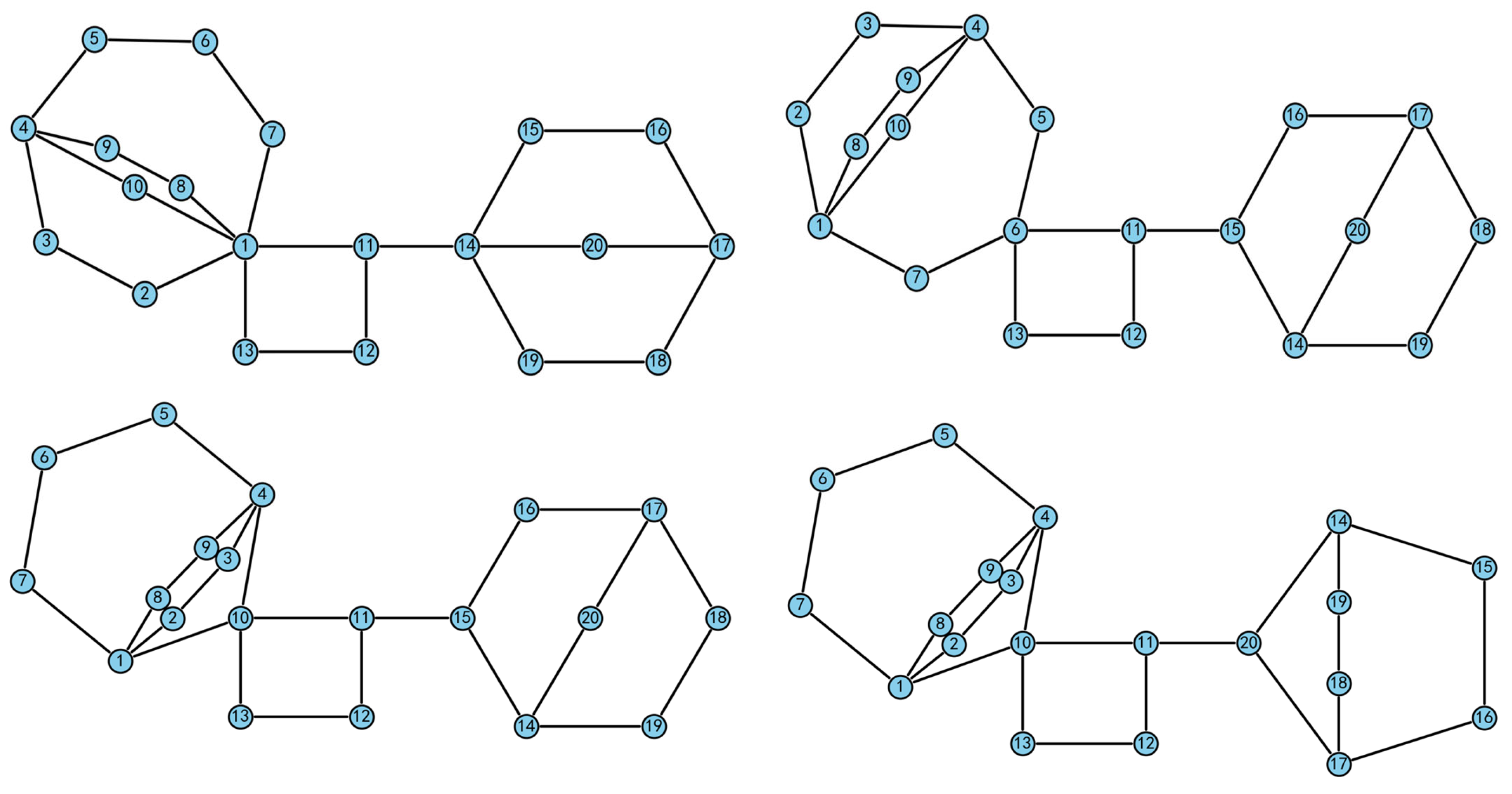
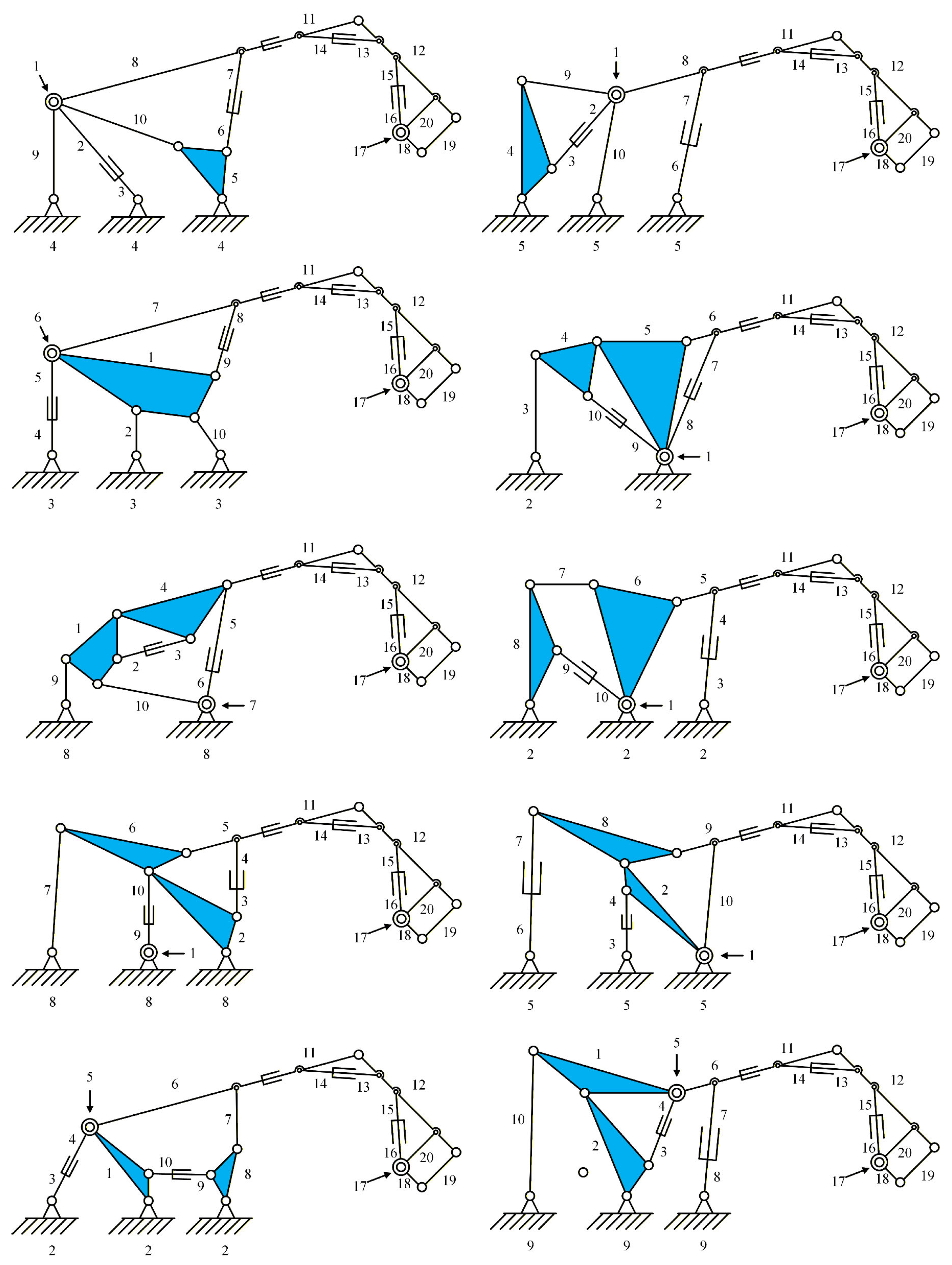
Section 5.1. The base and EE locations are then identified for each retained topology, yielding 249 feasible configurations. The result is shown in
Table 7, and representative mechanisms are illustrated in
Figure 19. Quantitative comparisons with the existing design in
Figure 1 are left for subsequent dimensional synthesis and performance optimization, whereas the present work focuses on topology-level generation and screening of feasible configurations.
6. Discussion
In
Section 5, 249 feasible configurations of the
N18_
M5 containing two MJs FKC were obtained from the separable topological graph atlas under the specified design constraints.
For a given KC1 subchain, multiple base–EE vertex pairs may satisfy the functional constraints. As shown in
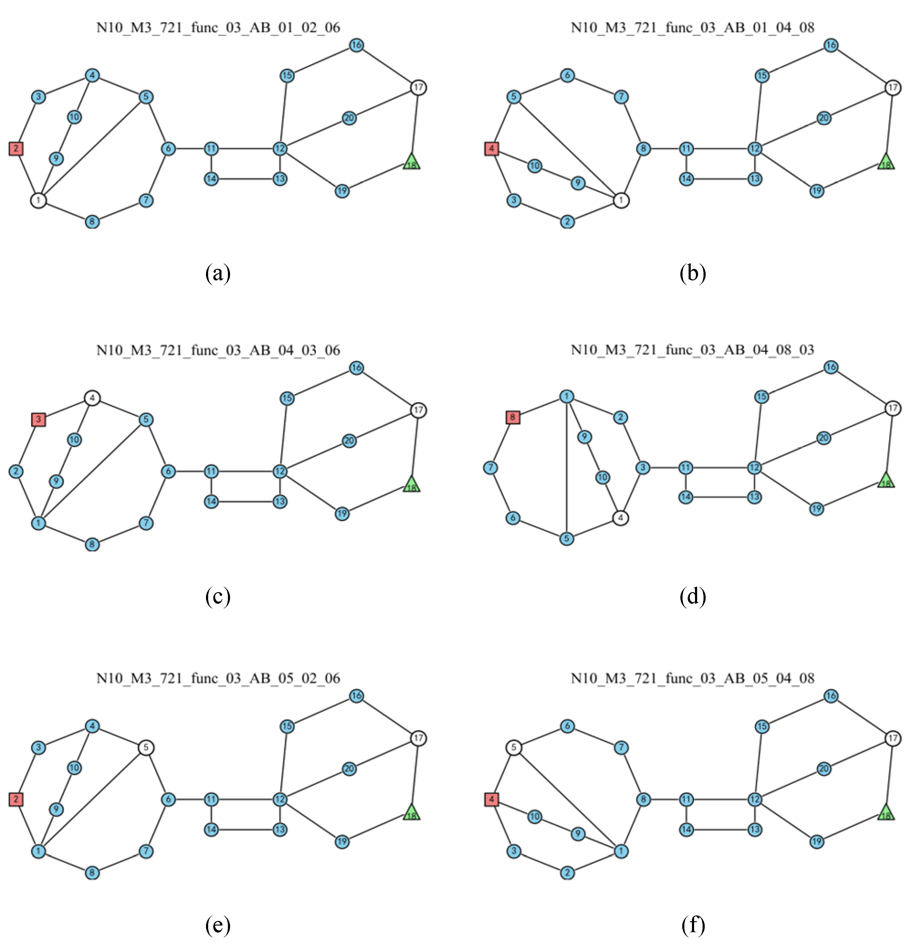
Figure 20, the six new mechanisms illustrated are all derived from the same topological graph. In this graph, the KC1 subchain contains three multiple-degree vertices,
,
and
, each of which can be equivalently transformed into an MJ. For each choice of multiple-joint vertex, several base–EE vertex pairs satisfy the connectivity criterion. Using the proposed method, this single topological graph yields 22 distinct configurations in total, providing a rich set of candidates for subsequent structural selection and dimensional optimization.
Examining all feasible configurations shows that the KC3 subchain admits a unique configuration. Under Rule S1, in order to allow the multiple-degree vertex to be equivalently transformed into an MJ, only the third topological graph in
Figure 9b is free of rigid subchains, all other candidates are excluded. This graph is symmetric, once the pair of binary vertices is modeled as a hydraulic cylinder, there is a single end-effector placement that satisfies the connectivity requirements. In the final KC3 configuration shown in
Figure 20a,
is the separation vertex between KC2 and KC3,
are equivalent to the hydraulic cylinder,
is equivalent to the MJ, and
serves as the EE.
Since KC2 and KC3 each have a unique configuration, each overall configuration can be labeled using the feature vertices of KC1. As shown in
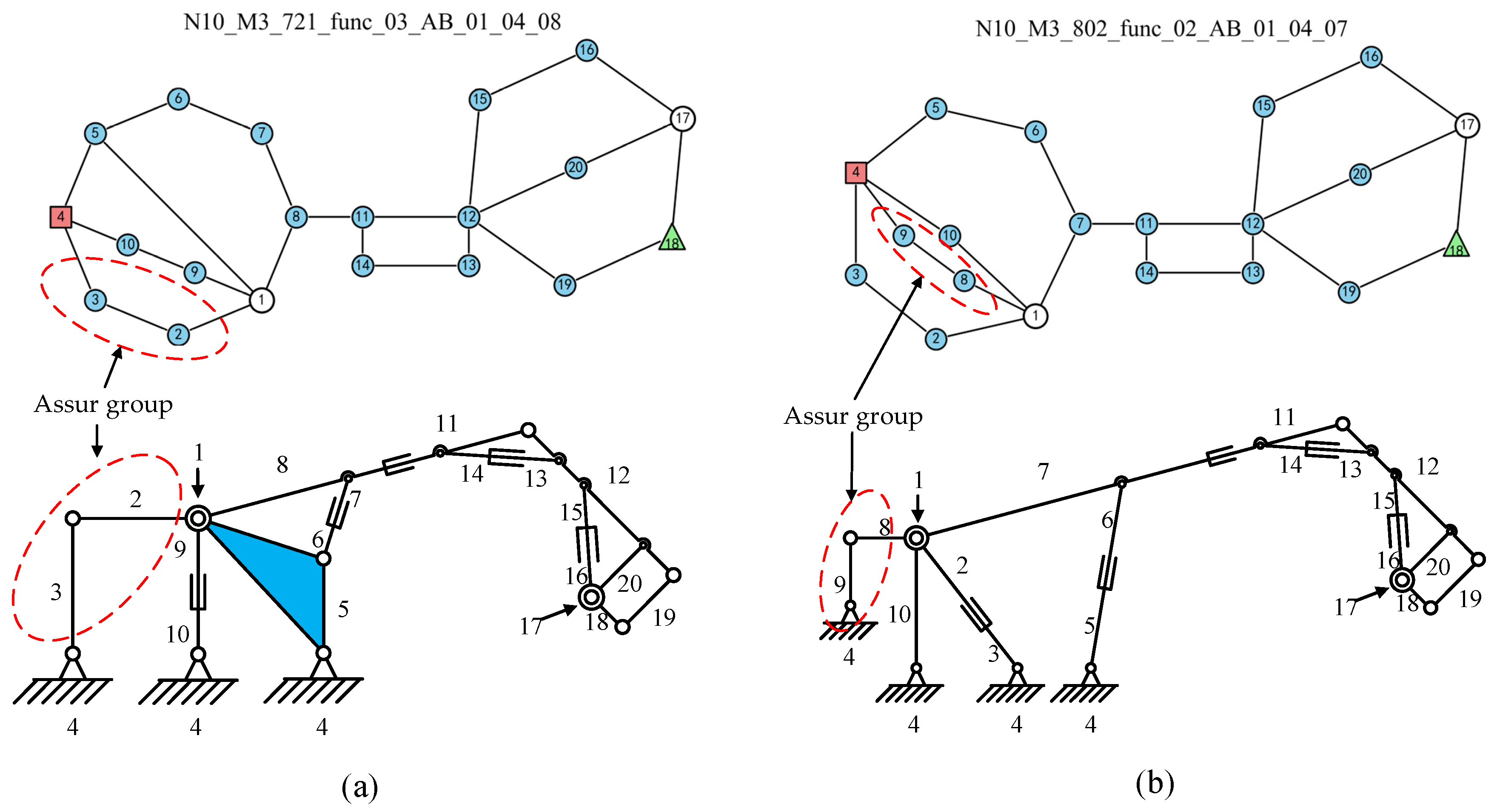
Figure 20b, the graph in this example is denoted as “N10_M3_721_func_03_AB_01_04_08”. Here, “N10_M3_721” encodes the link count, DOF, and LAA of KC1, respectively; “func_03” indicates that this configuration corresponds to the third topological graph, ordered by the base-vertex index in KC1 after functional-constraint screening within the LAA 721 atlas; “AB” specifies the combination mode of the three subchains; and “01_04_08” are the vertex labels of the MJ, the base, and the KC1–KC2 interface vertex in the KC1 subchain, respectively.
Some feasible configurations contain a second-order Assur group. As illustrated in
Figure 21a, when the link pairs
and
are modeled as hydraulic cylinders, links two and three form a second-order Assur group. Removing this Assur group does not change the overall DOF or the functional behavior of the mechanism. Consequently, the mine scaler manipulator arm can, in principle, be simplified from an
N18_
M5 FKC with two MJs to a
N16_
M5 FKC with two MJs while preserving its functionality.
A second-order Assur group appears only when the number of “22” binary–vertex chains in the topological graph exceeds two and the extra “22” chains cannot be converted into hydraulic cylinders. According to this rule, configurations containing a second-order Assur group can be identified in a straightforward manner. The corresponding statistics are summarized in
Table 8, and all topological graphs containing Assur group are listed in
Appendix A.1. From an engineering perspective, configurations without Assur groups are generally preferred as candidate configurations for the mine scaler manipulator arm.
Across all feasible configurations of the manipulator arm, three factors are found to influence performance. In addition to the choice of base degree and the selection of the equivalent multiple-joint vertex, as listed in
Table 7, the placement of the hydraulic driving pairs also has a significant impact on the workspace and dimensional design of the arm. According to whether the hydraulic actuator is directly connected to the telescopic boom, the configurations can be classified into two categories: directly connected and non-directly connected. Based on this classification, the statistics for all configurations are summarized in
Table 9, and the detailed statistics for each individual topological graph of KC1 are given in
Appendix A.2.
For the mine scaler application, directly connected structures with a multiple-degree base are preferred. Configurations that satisfy these criteria generally exhibit better workspace and closer similarity to existing industrial designs. This heuristic is used to form a shortlist; final selection requires dimensional optimization and performance evaluation.