1. Introduction
With the transformation of the global energy structure, renewable energy is developing rapidly. Energy storage technologies now face new opportunities and challenges. Among various energy storage solutions, FESS have been widely used. The energy storage system has the characteristics of high-power density, fast dynamic response, long cycle life, and excellent charge–discharge characteristics [
1,
2]. FESS applications include power quality improvement, aircraft power systems, marine power systems, and electric vehicles [
3,
4]. As the core component of FESS, the driving machine’s reliability and efficiency determine the overall system performance [
5]. Therefore, studying a high-reliability machine has significant engineering value.
Among the various machine types employed as drivers in FESS, permanent magnet synchronous machines (PMSMs) are a prominent choice due to their favorable characteristics. PMSMs are widely used not only in flywheel energy storage but also in transportation and industrial automation [
6,
7]. These machines exhibit high power density, efficient energy conversion, and an excellent dynamic response [
8,
9]. However, conventional three-phase PMSMs face limitations in high-speed operation, including limited fault tolerance, significant torque ripple, and high harmonic content. Such electromagnetic performance deficiencies restrict their applications in high-speed, high-reliability scenarios like flywheel storage. Therefore, innovative machine topology designs are urgently needed to enhance overall performance.
In recent years, remarkable progress has been made in the research on machine reliability [
10,
11]. Short-circuit current suppression has become a key focus in fault-tolerant permanent magnet (FTPM) machine studies. Multiple approaches have been proposed to address SCC mitigation. In [
12], the effectiveness of a phase shift (7.5 degrees) in a 48-slot 22-pole permanent magnet machine for reducing short-circuit current was studied. Concurrently, an FTPM generator with a secondary tooth structure was proposed [
13]. This structure can effectively suppress short-circuit current and ensure torque performance. In order to achieve high performance and strong fault-tolerant capability in key applications for machine drives, the double three-phase fault-tolerant machine adopts a multi-phase winding configuration and an optimized spatial layout. In [
14,
15], a permanent magnet fault-tolerant motor with a triple three-phase structure was proposed. This machine uses a star-triangle connected winding, demonstrating a higher fundamental winding factor and lower spatial harmonics, thereby generating greater average torque, less torque pulsation, and lower iron loss. Furthermore, a new auxiliary tooth structure for FTPM generators to achieve structural optimization was proposed [
16]. This structure not only enhances the fault-tolerant capability and reduces torque pulsation but also poses difficulties in manufacturing. Research on the analysis and modeling of machine fault currents has also been carried out in depth. To detect the fault current, an online short-circuit estimation method for permanent magnet motors was proposed [
17]. In order to analyze the short-circuit current during the inter-turn short-circuit fault of PMSMs, an equivalent circuit model was established [
18], which revealed the relationship between fault severity and circuit parameters. In [
19], the influence of contact resistance was further considered in the study, and the quantitative relationship between short-circuit current amplitude, fault resistance, and short-circuit turns was revealed. However, the assumption of constant contact resistance in these models shows limitations. Furthermore, the influence of healthy winding currents on the fault condition in the double three-phase surface-mount machines is mainly studied in [
20]. The study proposed suppression strategies for short-circuit currents and demagnetization. However, the insufficient consideration of various winding conditions limits the conclusion generality.
To address these needs and limitations, a double three-phase permanent magnet fault-tolerant machine (DTP-PMFTM) with low short-circuit current is proposed to meet the demands of high-reliability drive machines for FESS. The winding in this configuration is divided into multiple independent submodules. Through optimized spatial winding distribution, effective electrical, thermal, and physical isolation is achieved between the two winding sets. Consequently, the system’s fault-tolerant operation capability is significantly enhanced. The paper is organized as follows: In
Section 2, the basic structure of the DTP-PMFTM is introduced. In
Section 3, the different three-phase stator winding topologies are compared and analyzed based on the finite element method. In
Section 4, the influence of armature winding parameters on the electromagnetic performance of the machine is analyzed. In
Section 5, an experimental platform is built to verify the proposed topology. Finally, this article is concluded in
Section 6.
2. Machine Topology
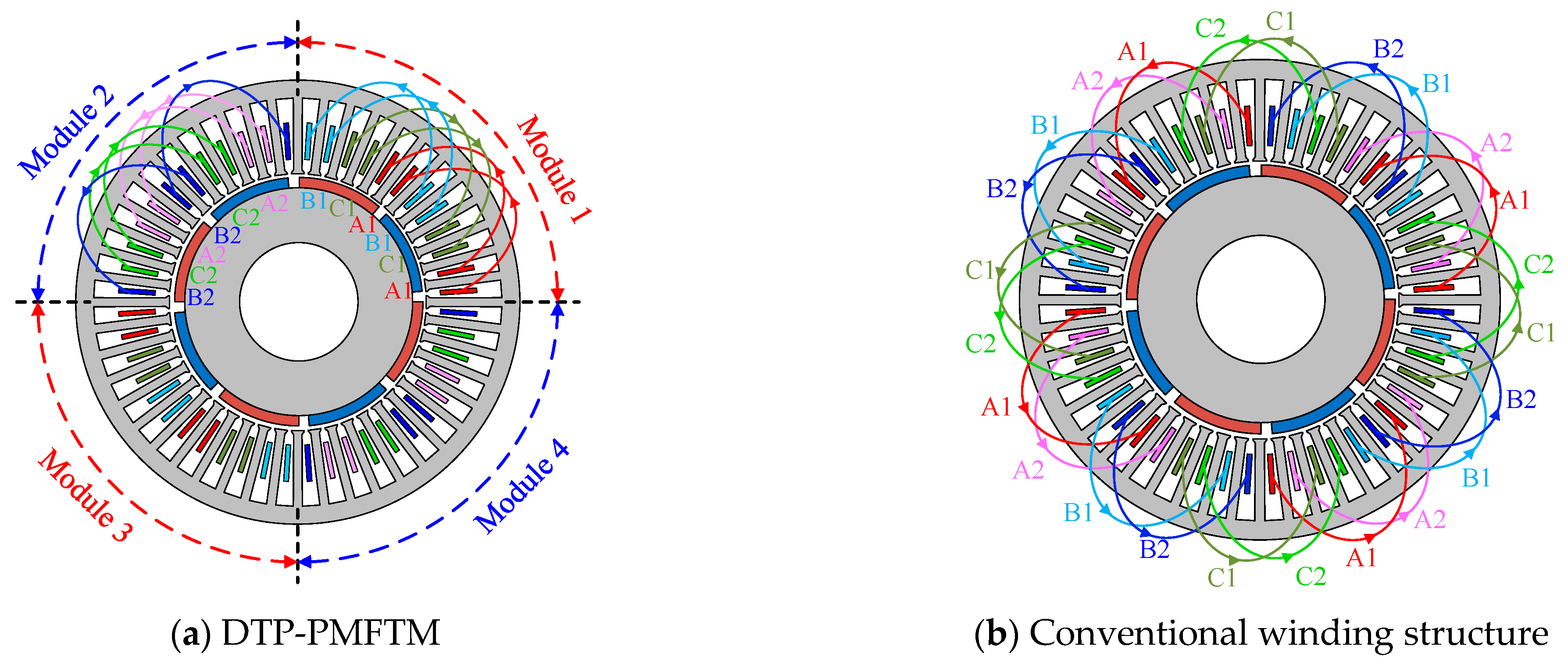
The proposed DTP-PMFTM is shown in
Figure 1a. The machine consists of an outer stator and an inner rotor. The stator contains armature windings and iron cores with a modular winding arrangement. Modules 1 and 3 share identical winding connections, while Modules 2 and 4 employ the same connection pattern. The three-phase windings of each module are independently distributed within the stator, with no spatial overlap between them. At the same time, the winding adopts a single-layer structure, which has the advantages of low harmonic content, simple structure, and excellent thermal dissipation. The conventional double-three-phase fault-tolerant machine topology is shown in
Figure 1b. Clearly, under the conventional winding structure, the coils of the two sets of windings are interleaved and stacked in space. Consequently, when one of the three-phase windings fails, it will cause the failure to spread to the other three-phase windings, thereby affecting the machine’s ability to operate with faults.
The rotor consists of iron rotor cores and surface-mounted PMs with radial magnetization. The magnets are directly attached to the rotor surface, resulting in a near-sinusoidal airgap flux distribution. This design effectively reduces torque ripple and improves operational stability.
4. Discussion
Based on the modular winding structure, the finite element model of the DTP-PMFTM is established. The dimension parameters of the machine are shown in
Table 1, and the simulation results are shown in
Figure 8. The no-load back EMF of the modular winding is approximately 302 V, which represents a 3.54% reduction in the fundamental amplitude of the back EMF compared to conventional designs. Moreover, the waveform quality is significantly improved by reducing the key harmonic components. Notably, phase B2’s special winding arrangement produces identical harmonic content to the other five phases. This indicates that there is no back EMF asymmetry problem in the modular winding structure.
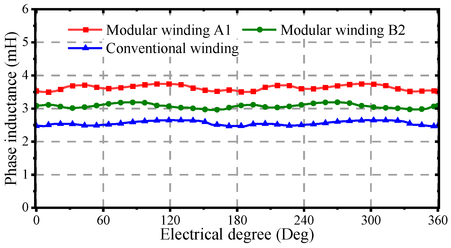
The phase inductance characteristics of the proposed DTP-PMFTM are further analyzed, with the results shown in
Figure 9. The conventional winding structure exhibits an average phase inductance of 2.8 mH. In contrast, the modular structure demonstrates 4.9 mH for phase A1 and 3.7 mH for phase B2. Compared with the traditional winding structure, the B2 phase inductance has increased by 32.1%. The results show that the inductance of each phase is significantly higher than that of the conventional structure after adopting the modular winding, and the fault tolerance performance is improved. Additionally, the inductance of phase B2 is obviously different from that of the other five phases due to its special winding arrangement.
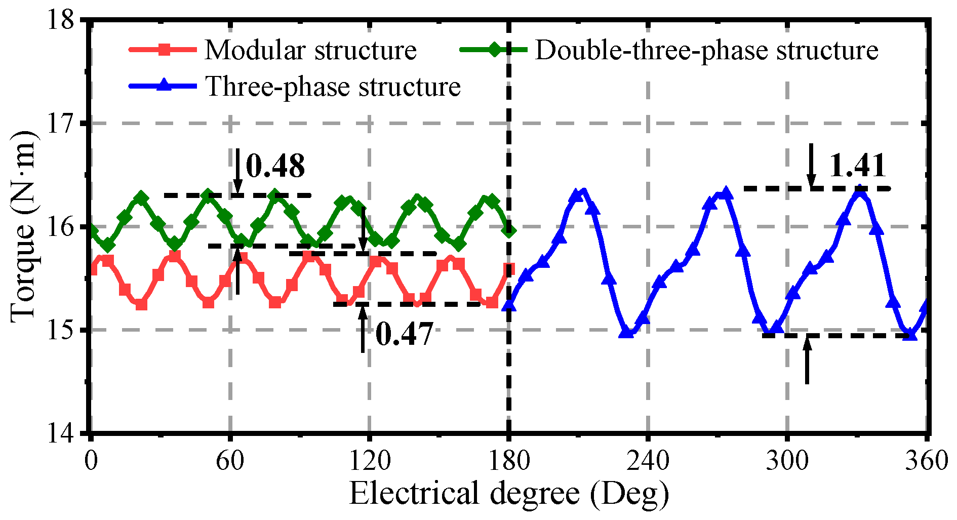
In order to evaluate the torque performance of the modular winding structure, a three-phase winding configuration serves as the control group. The simulation results are shown in
Figure 10. The average output torque of the modular winding structure is 15.48 N·m with a 10 A current. It is slightly lower than those of the conventional double-three-phase winding and three-phase winding structures. In addition, the double three-phase winding design exhibits superior torque ripple suppression. For these configurations, peak-to-peak torque ripples are 0.47 N·m, 0.48 N·m, and 1.41 N·m, respectively. These results confirm the effectiveness of modular winding in improving torque characteristics.
The flux density distributions of the modular and conventional structures are compared in
Figure 11. Under no-load conditions, the modular structure exhibits a peak flux density of 1.48 T in the stator yoke and approximately 0.67 T in the air gap, whereas the conventional structure shows 1.59 T in the yoke and 0.69 T in the air gap. Under load conditions, the modular structure reaches 1.60 T in the yoke and 0.76 T in the air gap, compared to 1.59 T (yoke) and 0.80 T (air gap) for the conventional structure. It can be seen that there are certain differences in the flux density distribution of the two structures. The air gap flux density in the modular structure is relatively stable and changes little, indicating that its magnetic field distribution is more uniform, which is conducive to improving the overall performance of the machine.
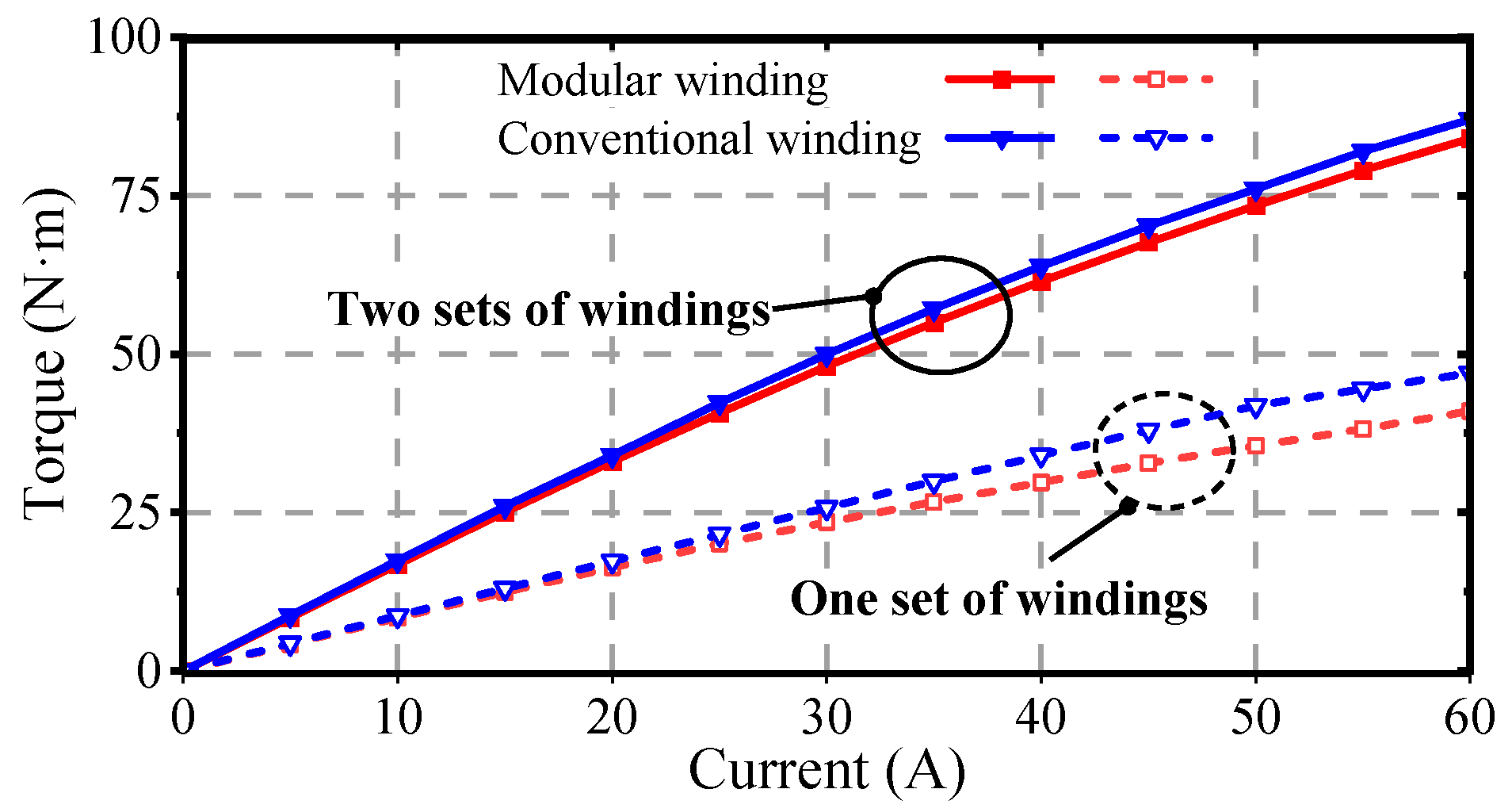
The peak-to-peak torque variation with current for the machines using different winding configurations is shown in
Figure 12. Overall, as the phase current amplitude increases, the conventional double three-phase winding shows a slight advantage in torque ripple suppression. The variation of average torque with phase current for the different winding configurations is shown in
Figure 13. It can be observed that the modular structure achieves a smaller torque ripple but compared to the traditional dual three-phase winding configuration, it exhibits a slight decrease in the average torque.
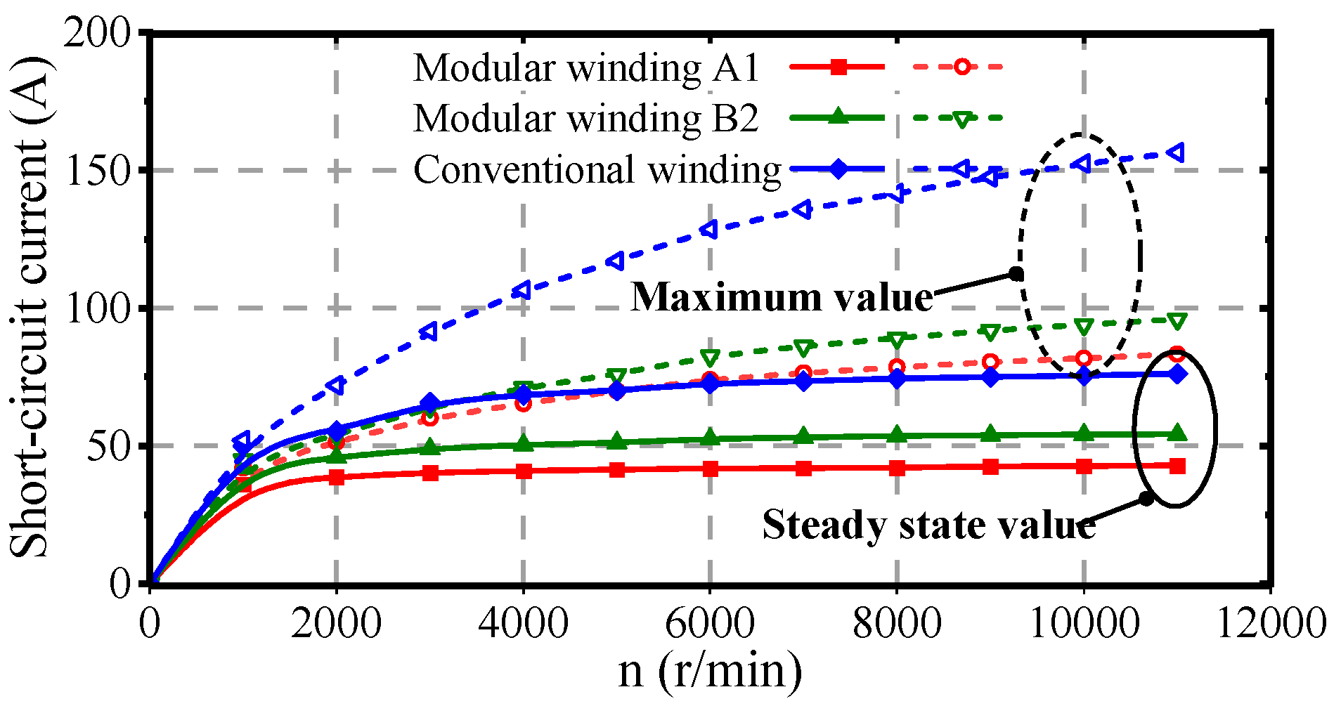
The modular winding structure leads to differences between the inductance characteristics of phase B2 and the other five phases. It is necessary to consider both phase A1 and phase B2 short-circuit conditions. The short-circuit current characteristics versus speed for different winding structures are shown in
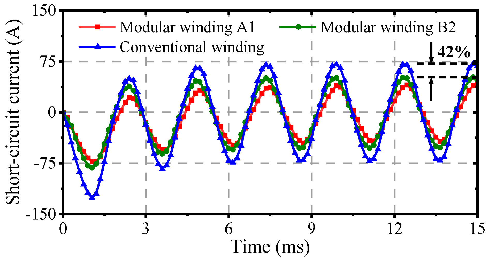
Figure 14, with identical phase resistance of 0.86 Ω. The results show that the modular winding structure is superior to the conventional structure in both the maximum and steady-state values of short-circuit current, demonstrating better short-circuit current suppression ability. Furthermore, the dynamic response curves of short-circuit currents at rated speed (6000 r/min) are shown in
Figure 15. The maximum short-circuit current is 72.5 A with the conventional winding structure but only 50.9 A with the modular winding, representing an approximately 29.7% reduction. These results clearly demonstrate the characteristic differences among various winding structures under short-circuit conditions.
5. Experimental Validation
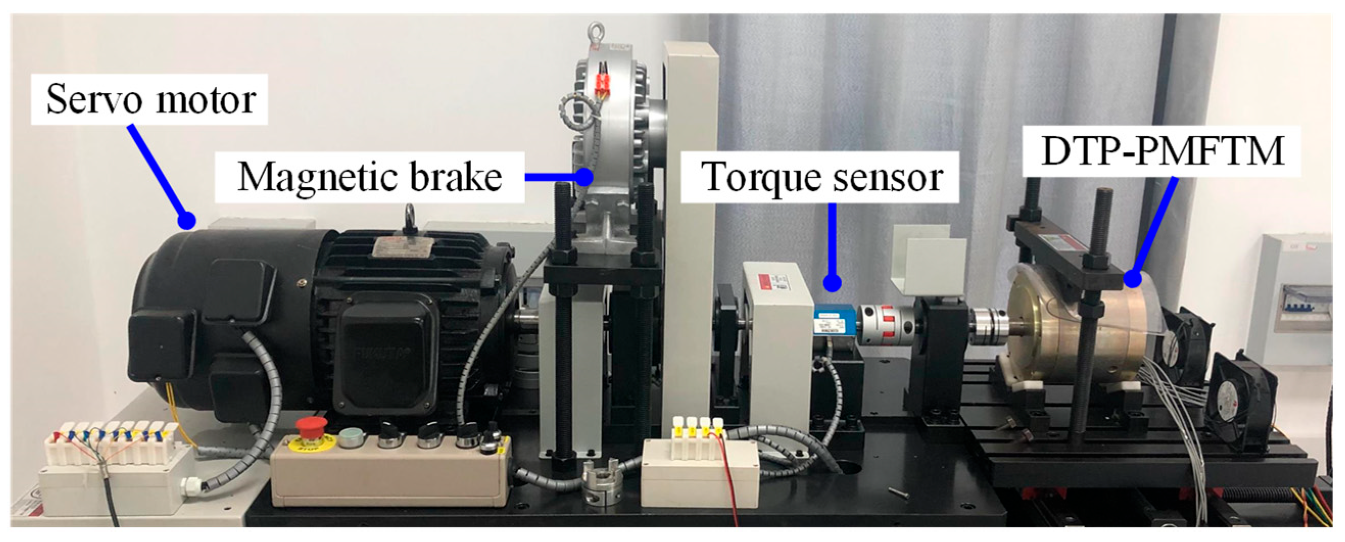
Based on the theoretical analysis above, the DTP-PMFTM can be built and tested. The experimental platform is shown in
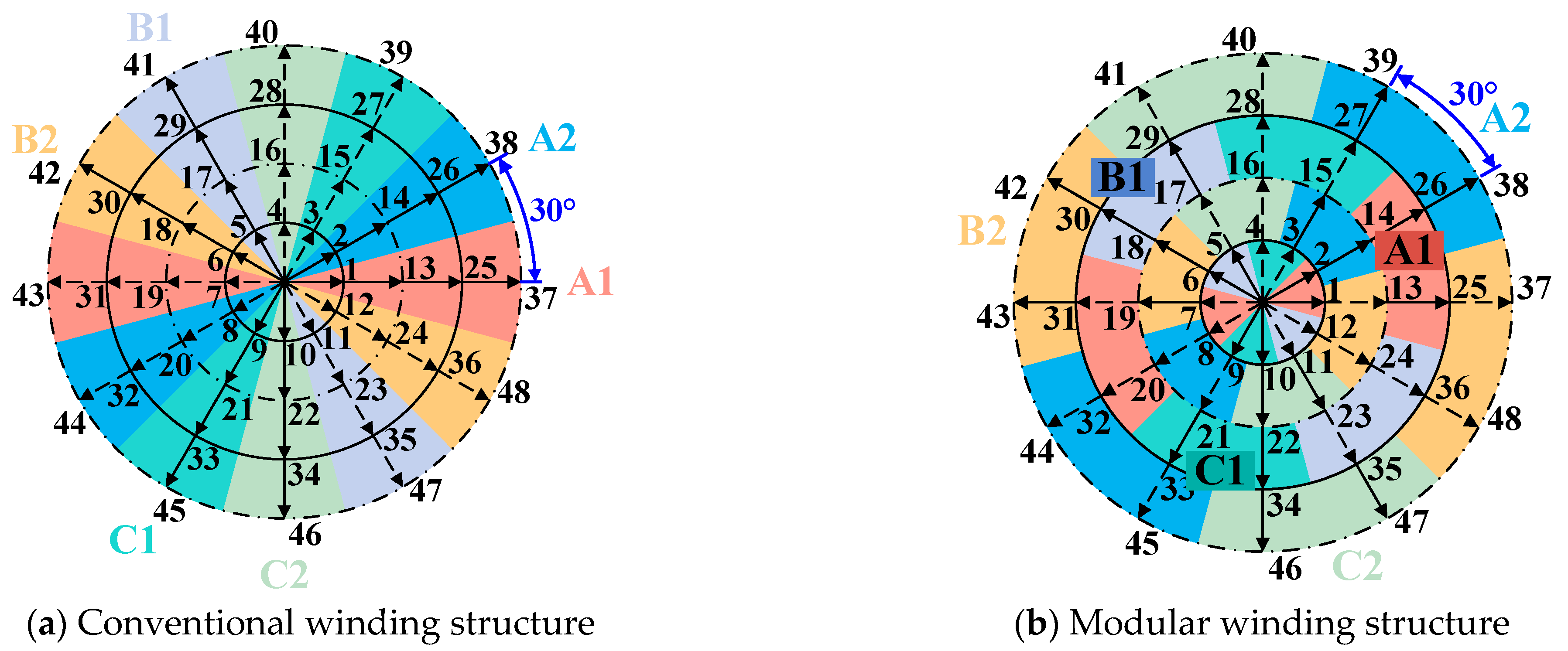
Figure 16. The stator windings employ a modular winding configuration with a 30° phase shift. To minimize iron losses, the core is constructed through axial stacking of silicon steel laminations.
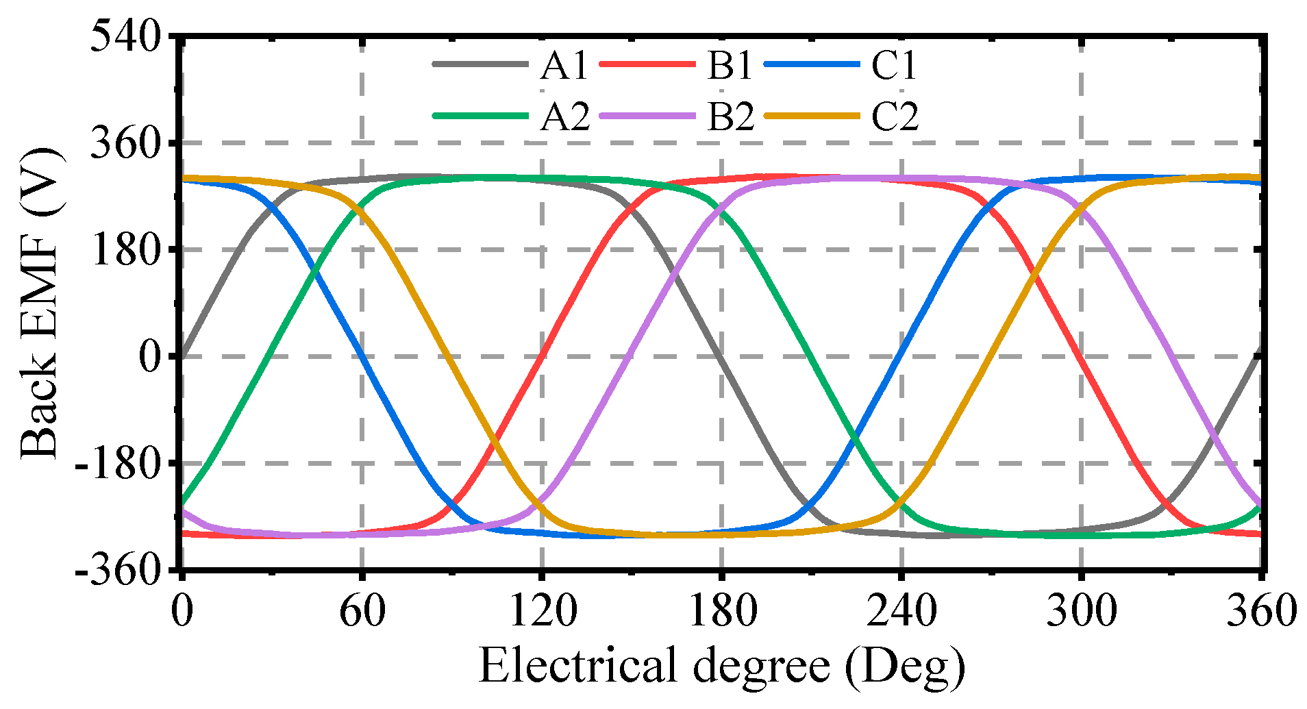
The back-EMF waveforms of the machine are presented in
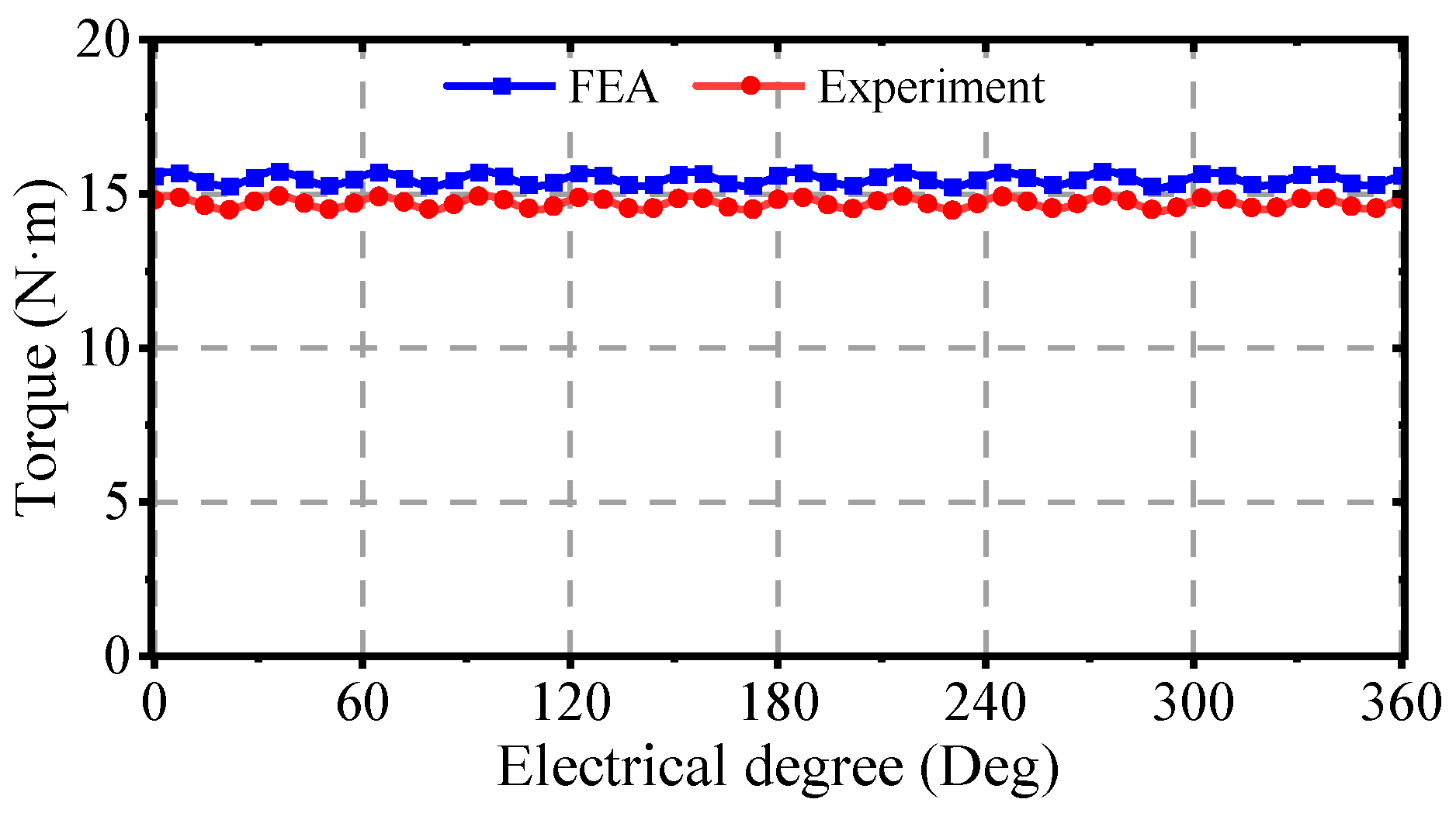
Figure 17. It can be seen that the back-EMF of phase B2 winding remains symmetric with the other five-phase windings, and the amplitude of each harmonic is equal to 302.2 V. However, the measured waveform amplitudes are lower than the simulated values. This discrepancy primarily results from manufacturing tolerances and measurement errors in the system. The torque–current characteristics of the prototype with modular winding configuration are shown in
Figure 18. The experimental results demonstrate an average torque of 14.7 N·m.
The experimental and simulated short-circuit current results of the DTP-PMFTM are shown in
Figure 19. The measured values for phases A1 and B2 under the modular winding configuration are 37.68 A and 47.19 A, respectively, while the corresponding simulated values are 40.54 A and 51.29 A. Overall, the tested current curves show good agreement with the simulation results, though with slightly lower magnitudes. This discrepancy primarily results from the 2D finite element model’s omission of winding end leakage inductance.
6. Conclusions
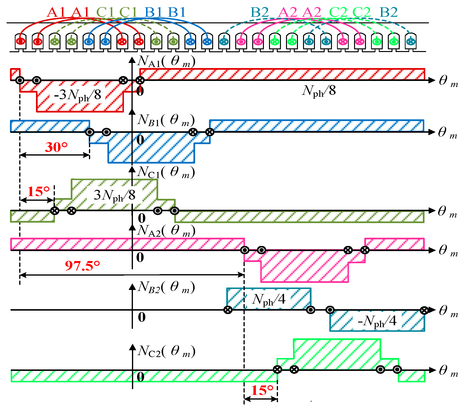
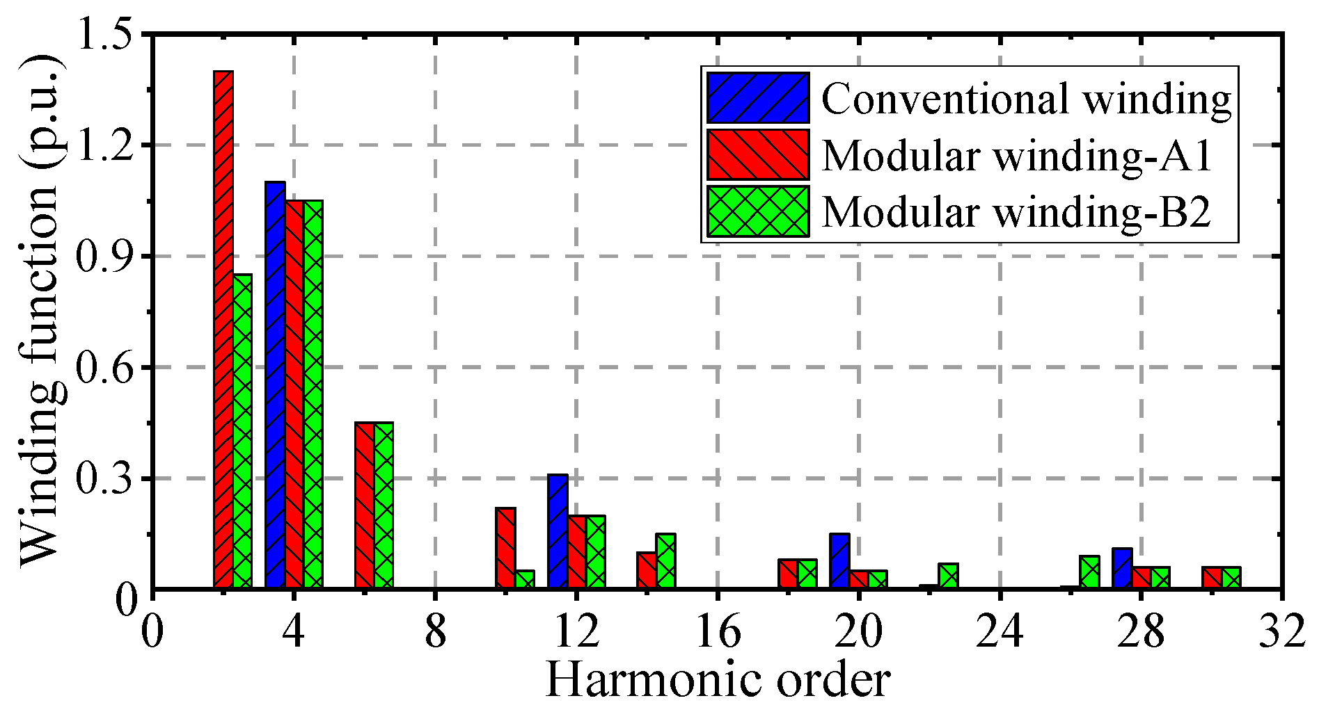
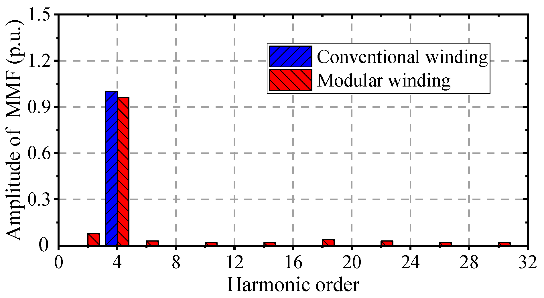
In this paper, a double three-phase permanent magnet fault-tolerant machine (DTP-PMFTM) is proposed for flywheel energy storage systems. The machine not only retains the advantage of low torque ripple offered by the conventional double three-phase 30° winding structure but also achieves excellent physical isolation through the optimization of the winding distribution. Compared to the conventional winding structure, the modular winding structure increases the phase inductance by approximately 32.1% and reduces the short-circuit current by more than 29.7%, thereby enhancing the machine’s fault-tolerant operation capability. However, the modular winding structure also results in an asymmetric spatial distribution of phase B2 relative to the other five phases, leading to an irregular distribution of the winding MMF. Research demonstrates that the modular structure introduces harmonic components at multiples of non-pole numbers such as the 2nd, 10th, 14th, and 18th harmonics, which increase the leakage inductance in the air gap. In addition, the harmonic content of phase B2 is different from the other five phases. The harmonic content of the 4th, 12th, and 20th harmonics affecting the no-load back EMF remains consistent, ensuring that the back EMF of each phase in the modular winding structure remains symmetric. It is worth noting that the modular winding structure also has the disadvantage of a slightly lower average torque when two sets of windings are in operation and a significant decrease in overload capacity when only one set of windings operates. Finally, a prototype was built and tested. The experimental results validate the theoretical analysis and simulation outcomes.
