
Fast Simulation and Optimization Design of a Slotless Micro-Motor for High-Speed and High-Flow Pumps

 , ,
, ,
Abstract
1. Introduction
- New Types of Winding: Burnand et al. designed a novel winding using additive manufacturing techniques, which resulted in reduced coil resistance and a 24% increase in the motor constant [15,16]. Dehez et al. optimized the geometry of flexible printed circuit board (FPCB) coils, thereby maximizing back electromotive force (back-EMF) and minimizing resistance [17,18,19,20,21].
- Halbach Magnet Array Rotor: When optimizing a slotless PMSM with a Halbach array for copper loss minimization, research indicates that a configuration utilizing a magnetic rotor and NdFeB magnets achieves the highest efficiency with sinusoidal input current. This is attributed to its superior utilization of magnetic loading, outperforming configurations with NdFeB magnet arrays on nonmagnetic rotors [22]. Furthermore, studies have confirmed that optimizing the Halbach magnet array enhances electromagnetic torque [23].
2. The Principle of Stratified Co-Simulation for a Slotless Motor
2.1. Hexagonal Winding Structure
2.2. Technical Principle
2.3. Segments Parameter Calculation
3. Motor Design
3.1. Requirements
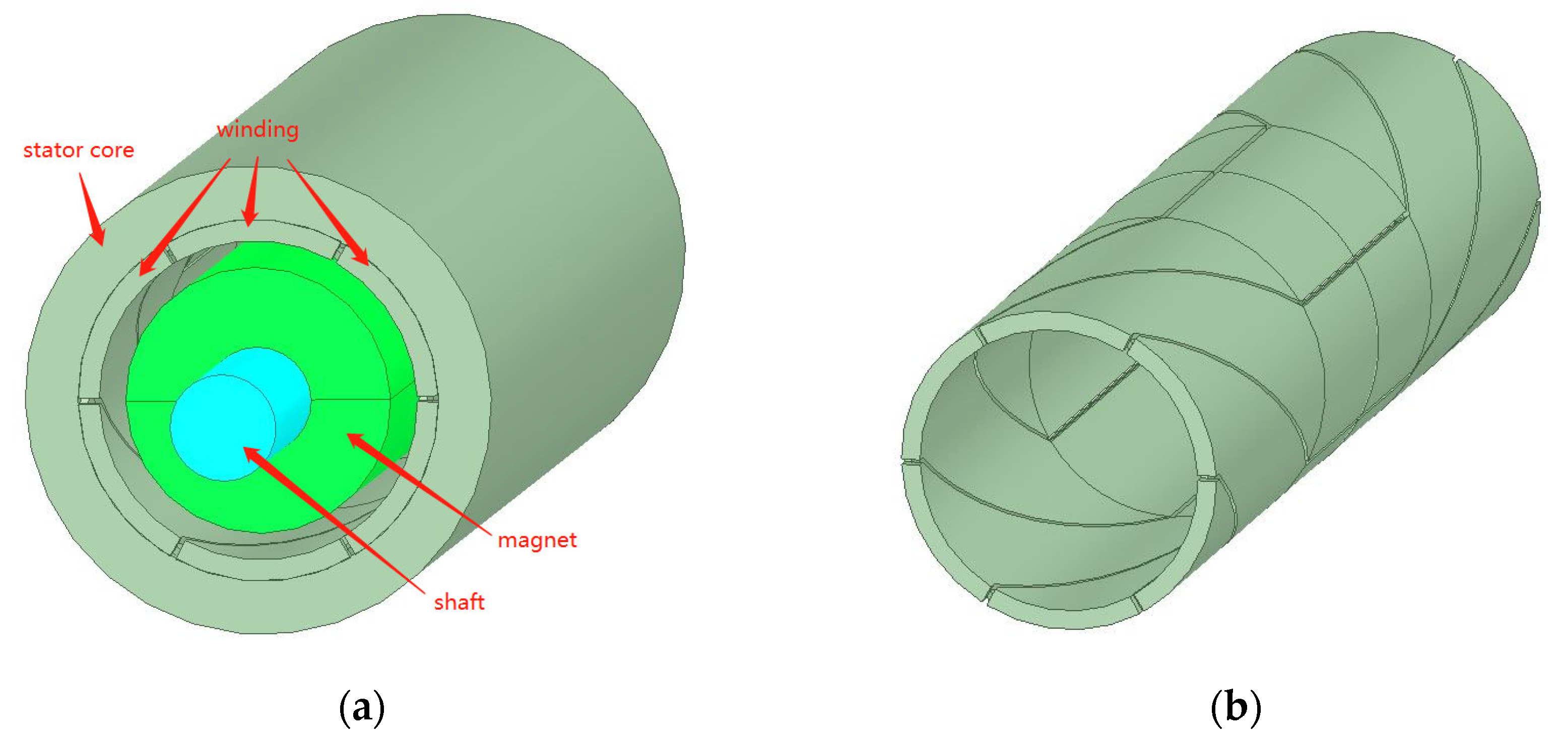
3.2. Model
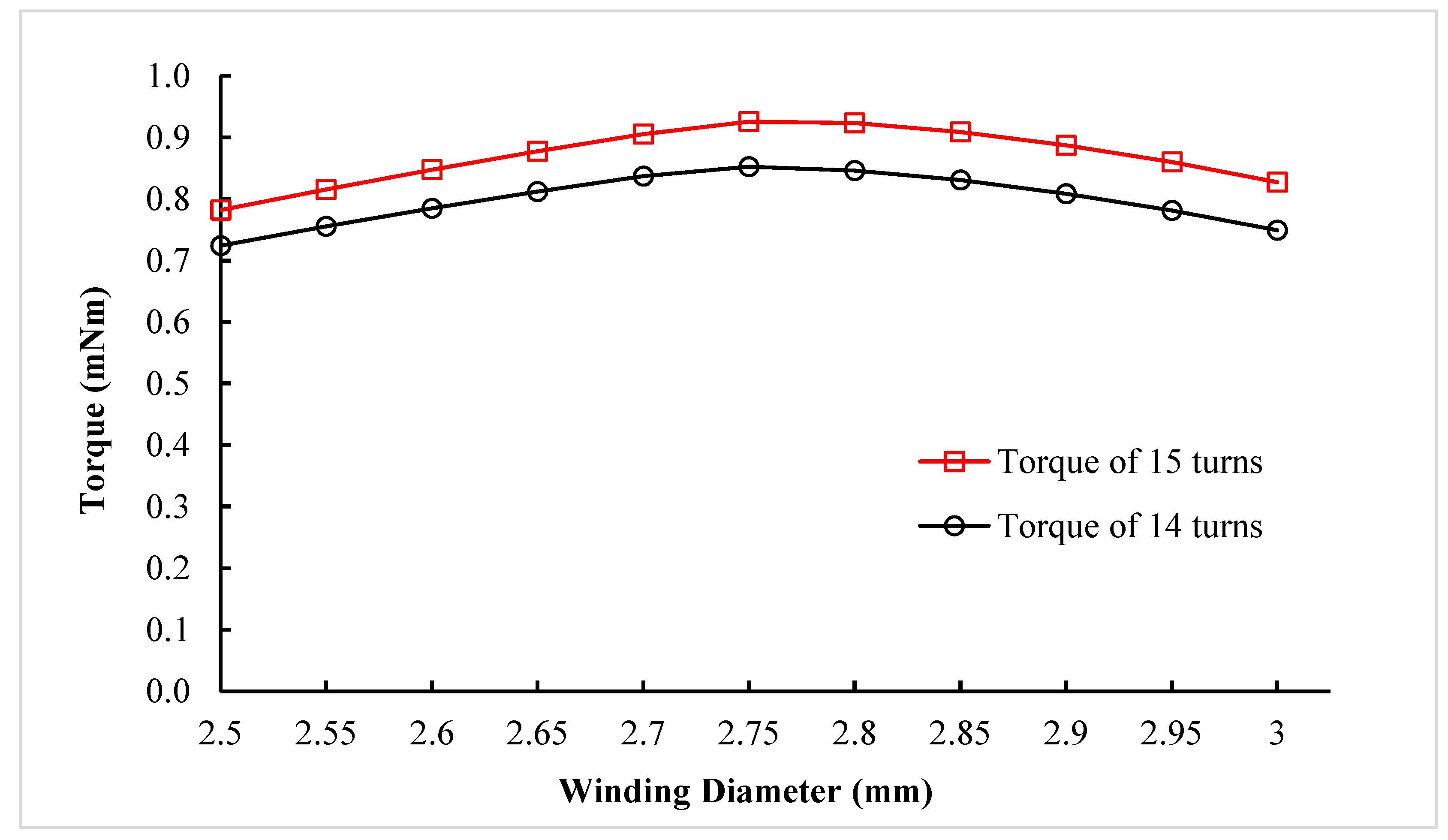
3.3. Optimization Design
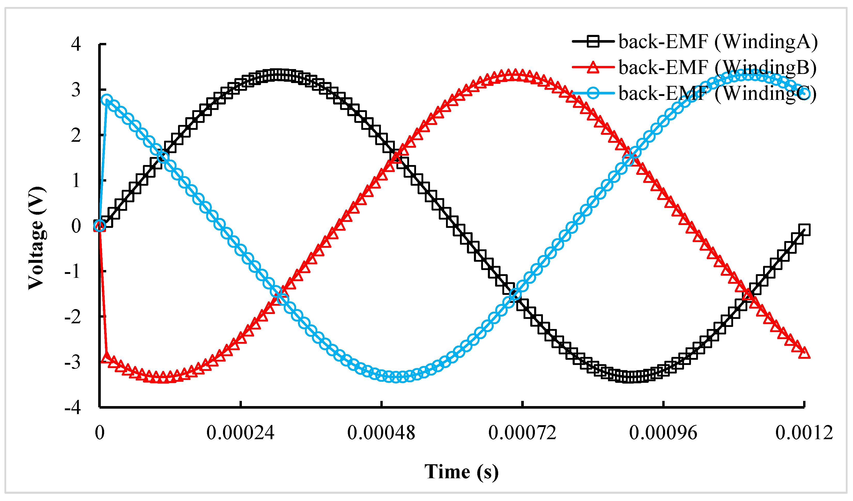
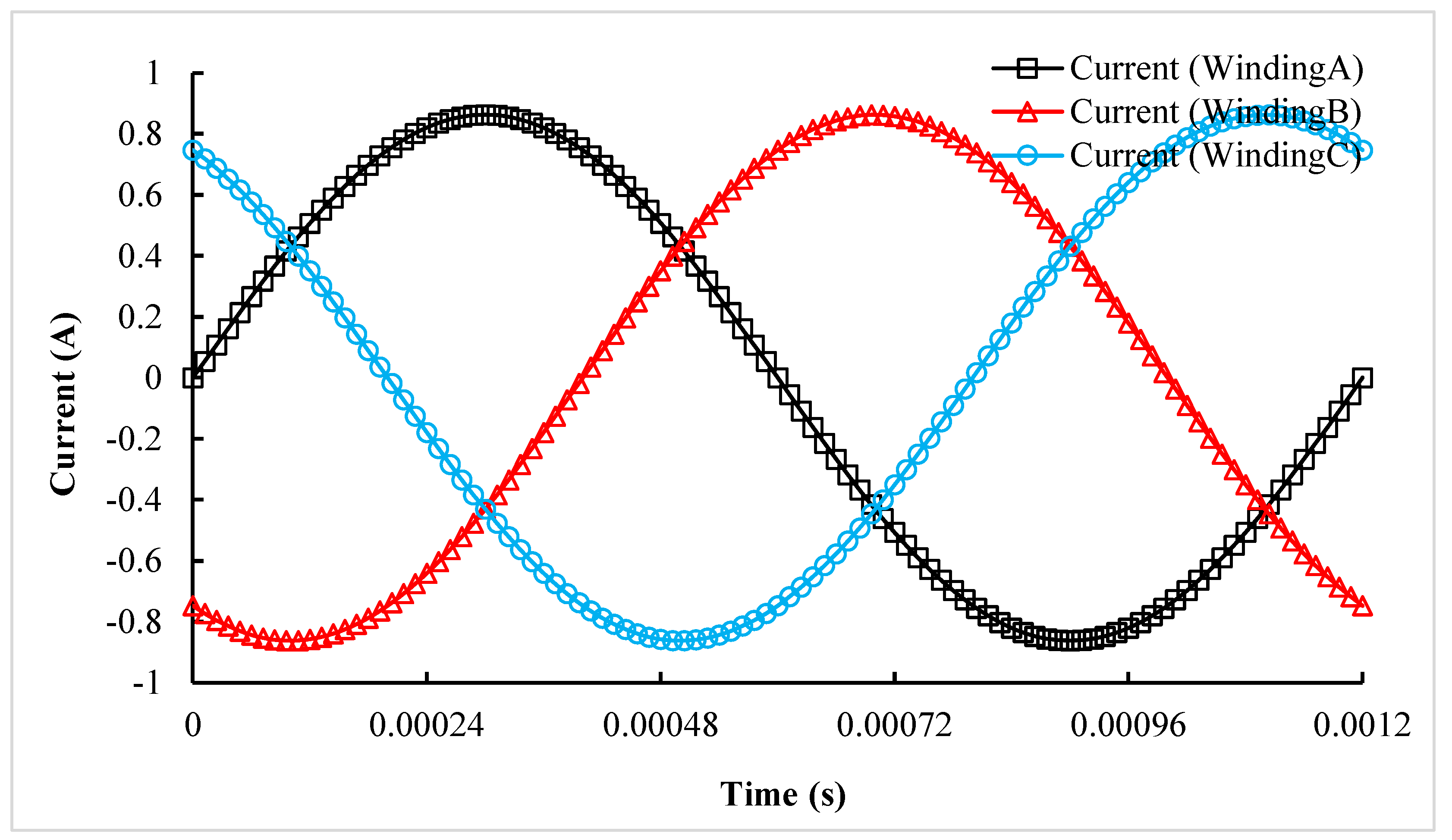
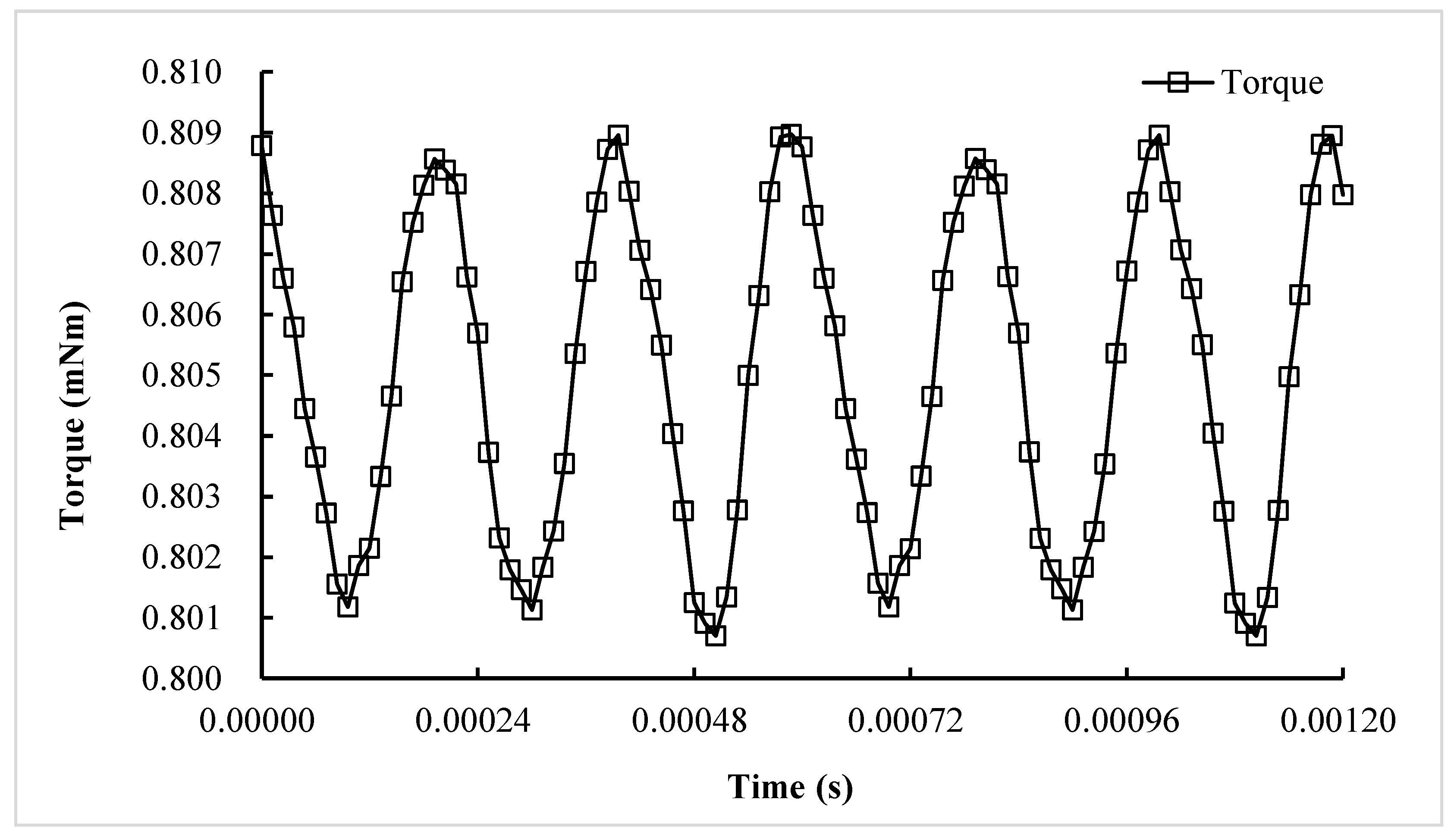
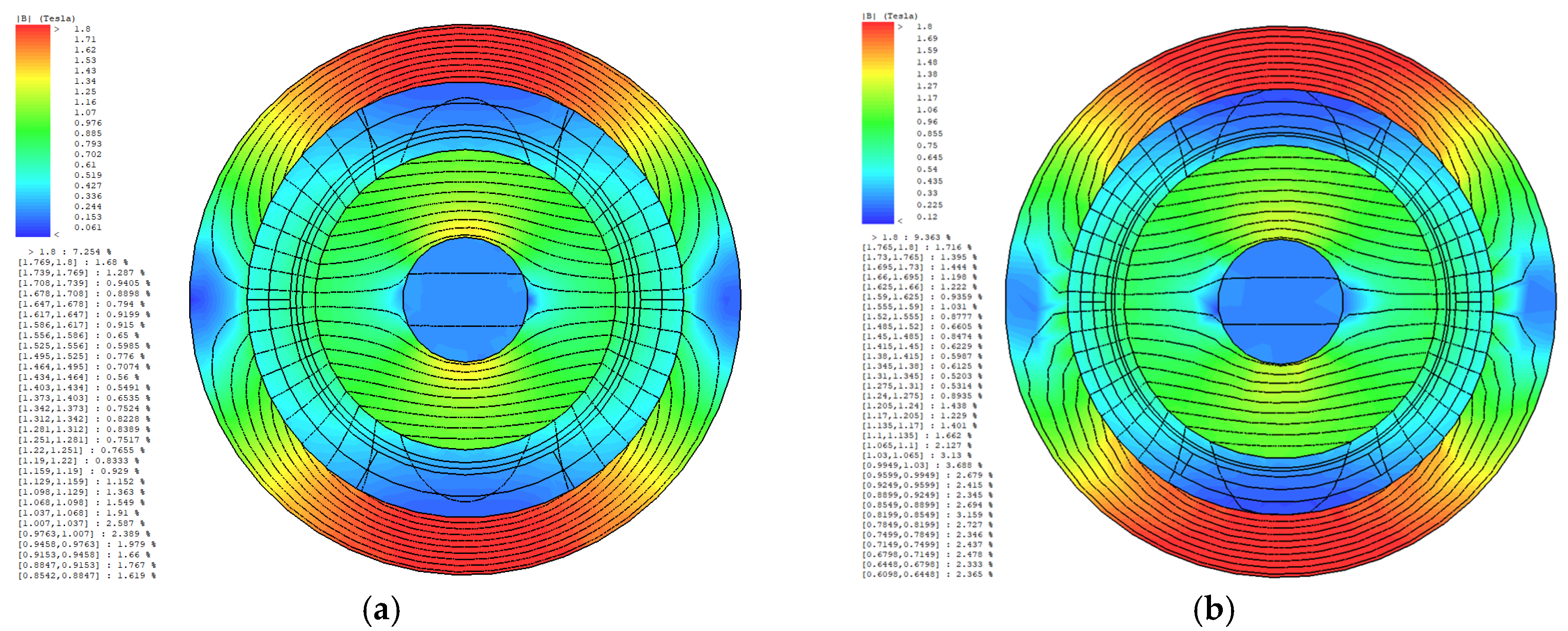
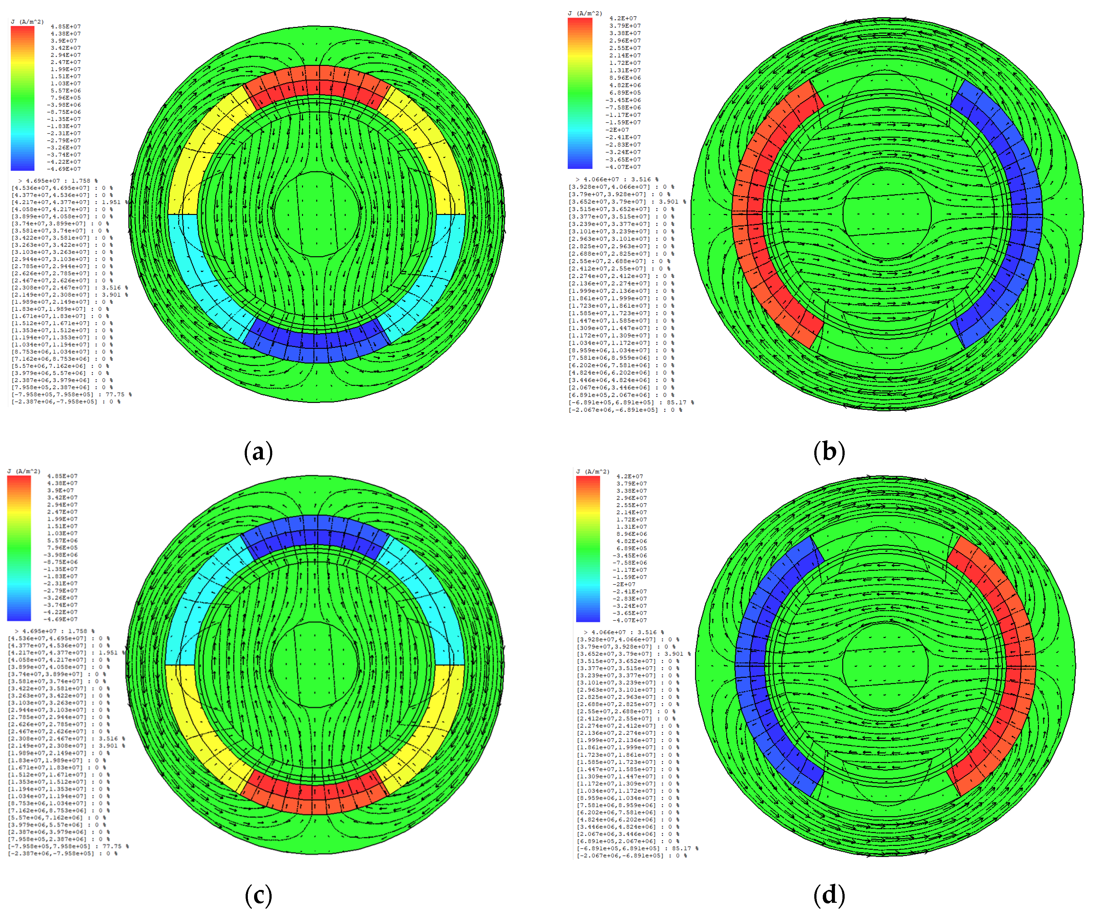
3.4. Two-Dimensional Optimal Solution Validation Simulation
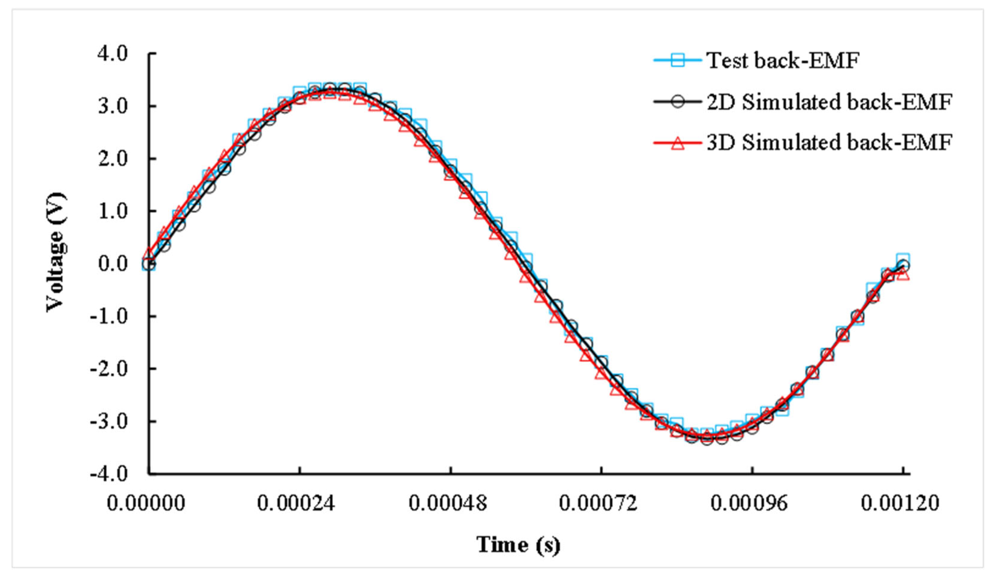
3.5. Three-Dimensional Optimal Solution Verification
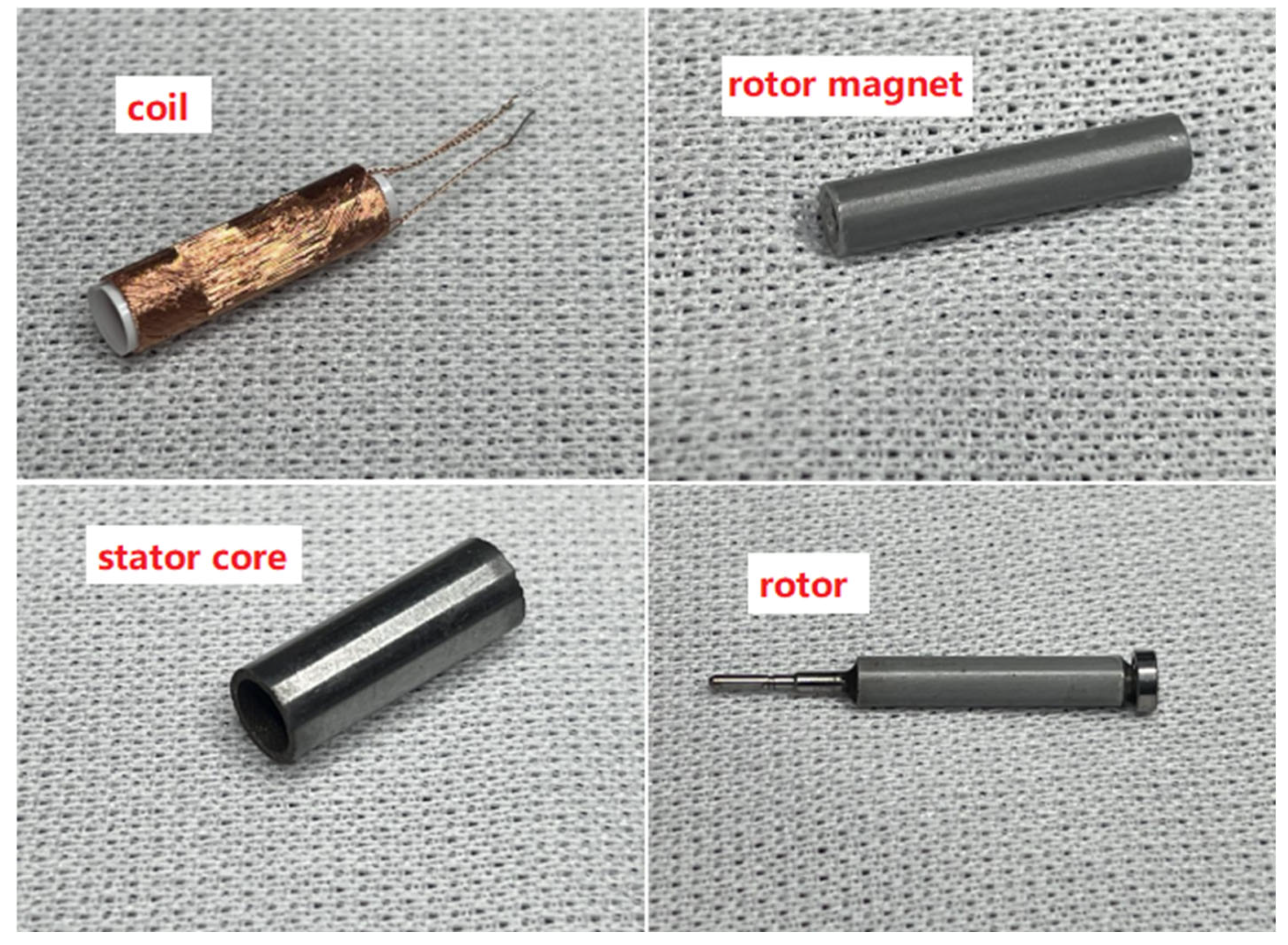
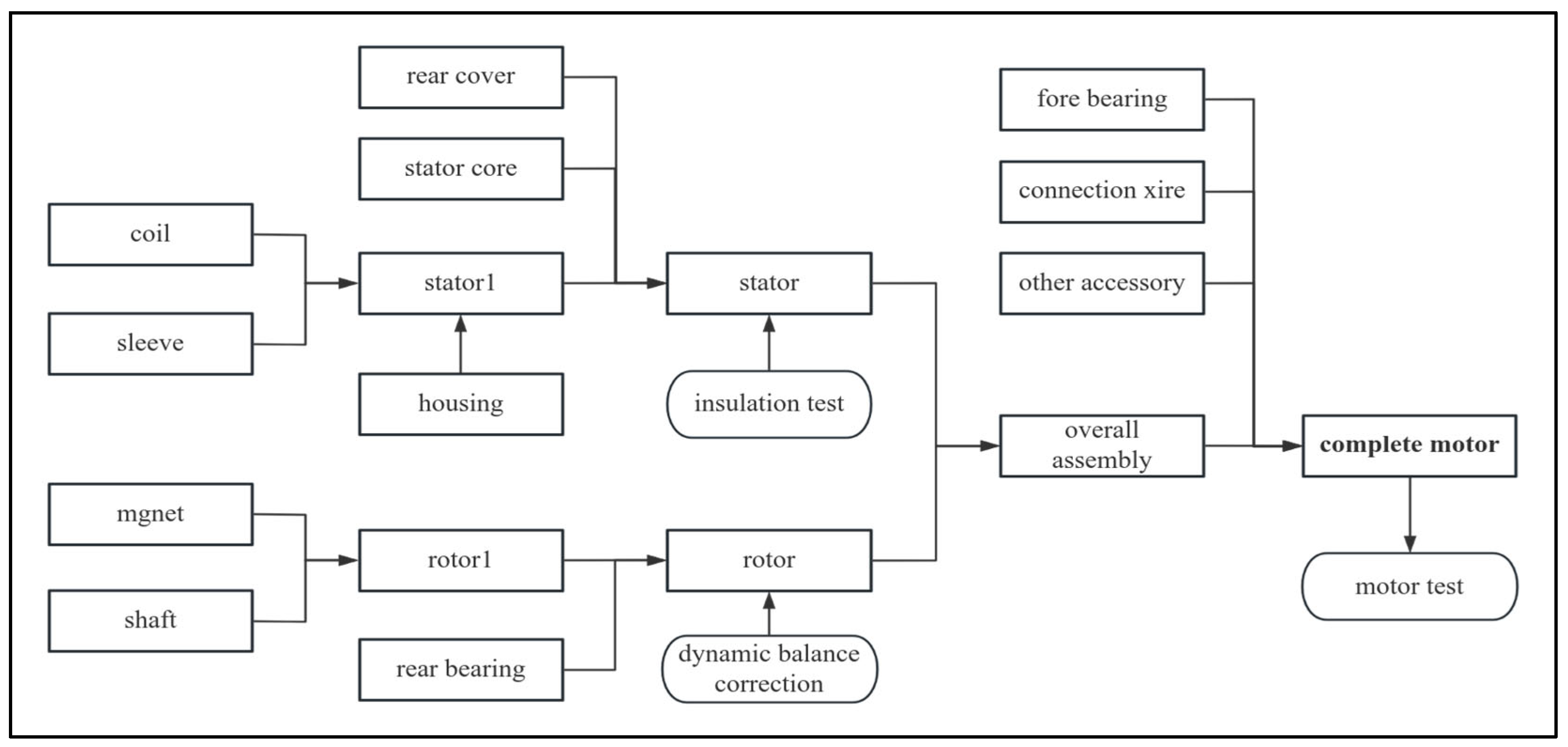
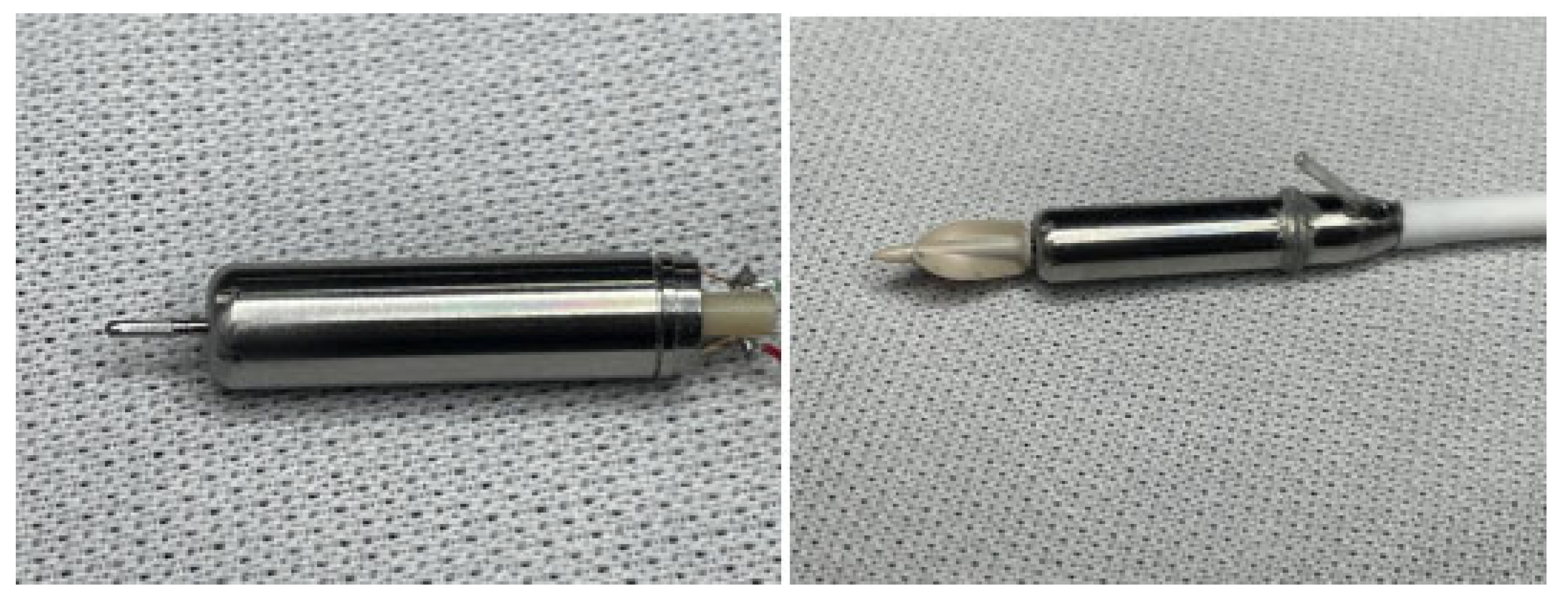
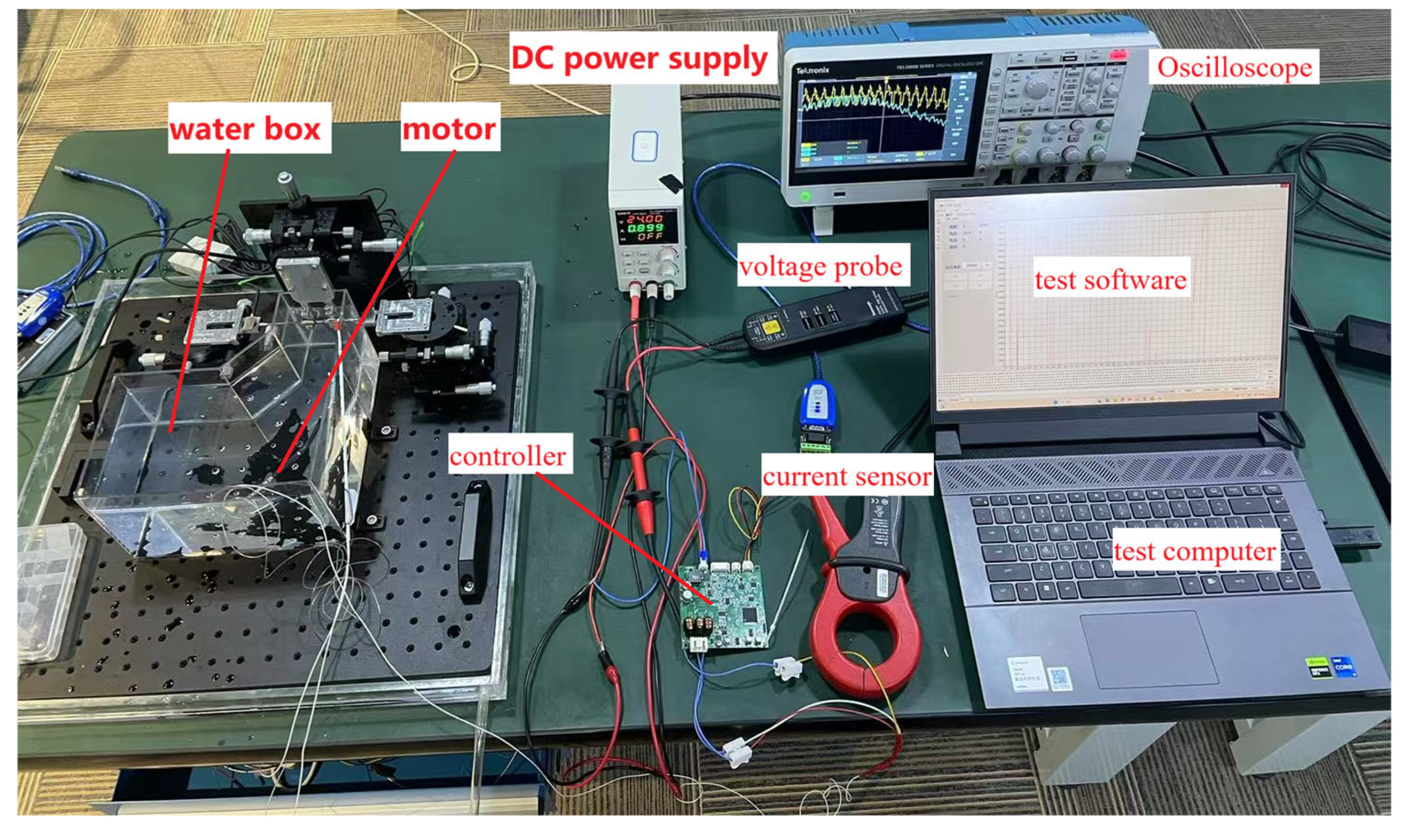
4. Prototype Manufacturing and Testing
5. Conclusions
- The novel 2D method overcomes traditional accuracy limitations, reducing simulation time to minutes while preserving electromagnetic fidelity, ideal for micromotor optimization.
- The 4.5 mm-diameter prototype exhibits back-EMF measurement errors within ±2% and stable performance at 50,000 r/min, validating the model’s engineering utility.
Limitations and Future Work
- The proposed method effectively addresses coil length variations relative to stator core and rotor magnet dimensions but has not yet investigated scenarios where stator core and rotor magnet lengths differ. Future research will prioritize simulations for designs with mismatched stator core, rotor, and winding lengths to improve accuracy.
- Load decoupling tests were limited by the motor’s low torque and the high dynamometer inertia, which prevented direct load measurements. Current tests rely on pump-head operation in water, which cannot quantify load torque–current relationships. Subsequent studies will focus on dynamometer-based load testing, loss separation, and thermal analysis for high-speed motors.
- A critical area for future exploration is bearingless magnetic suspension technology, which offers advantages such as eliminating material wear, reducing heat generation, and lowering sealing/corrosion resistance requirements. This innovation is particularly promising for applications like left ventricular assist pumps, where it minimizes red blood cell damage and thrombosis risks, thereby extending pump lifespan. Research on bearingless micromotors will be prioritized to leverage these benefits.
- Future work should address nonlinear materials, thermal coupling, and intelligent manufacturing integration.
Author Contributions
Funding
Data Availability Statement
Conflicts of Interest
References
- Liu, C. Emerging Electric Machines and Drives—An Overview. IEEE Trans. Energy Convers. 2018, 33, 2270–2280. [Google Scholar] [CrossRef]
- McKellar, S. A History of Mechanical Circulatory Support. In Mechanical Support for Heart Failure; Karimov, J., Fukamachi, K., Starling, R., Eds.; Springer: Cham, Switzerland, 2020. [Google Scholar] [CrossRef]
- Wang, F.; Zhu, Y.; Wang, H.; Zhao, D. Design and Analysis of a Bearingless Permanent-Magnet Motor for Axial Blood Pump Applications. IEEE Access 2020, 8, 7622–7627. [Google Scholar] [CrossRef]
- Sahnoune, A.; Hage-Hassan, M.; Krebs, G.; Marchand, C.; Guihaire, J.; Mercier, O. Design and analysis of a Circulatory Assistance Benchmark Actuator for an Artificial Lung. In Proceedings of the 2022 International Conference on Electrical Machines (ICEM), Valencia, Spain, 5–8 September 2022; pp. 827–833. [Google Scholar] [CrossRef]
- Arslan, S.; Iskender, I. Design aspects of a 26500-r/min: 2-kw high-speed permanent magnet synchronous generator for turbomachinery systems. In Proceedings of the 2016 8th International Conference on Electronics, Computers and Artificial Intelligence (ECAI), Ploiesti, Romania, 30 June–2 July 2016; pp. 1–6. [Google Scholar] [CrossRef]
- Liu, T.H.; Cheng, T.T. High-performance Micro-PMSM Control Systems including State-estimators. In Proceedings of the 2023 11th International Conference on Power Electronics and ECCE Asia (ICPE 2023—ECCE Asia), Jeju Island, Republic of Korea, 22–25 May 2023; pp. 675–680. [Google Scholar] [CrossRef]
- Yan, G.J.; Lin, R.B.; Jian, M.H. Improvement on the core loss of high speed slotless PMBLDC motor and its measurement. In Proceedings of the 2012 15th International Conference on Electrical Machines and Systems (ICEMS), Sapporo, Japan, 21–24 October 2012; pp. 1–4. [Google Scholar]
- Abdi, B.; Milimonfared, J.; Moghani, J.S. Simplified design of slotless halbach machine for micro-satellite Electro-Mechanical Batteries. In Proceedings of the 5th IET International Conference on Power Electronics, Machines and Drives (PEMD 2010), Brighton, UK, 19–21 April 2010; pp. 1–5. [Google Scholar] [CrossRef]
- Lee, Y.S.; Jang, I.S.; Yang, I.J.; Kim, K.S.; Kim, W.H. Study on the Slotless PM Motor Design Process Considering High Speed. IEEE Trans. Magn. 2024, 60, 8203804. [Google Scholar] [CrossRef]
- Bianchi, N.; Bolognani, S.; Luise, F. High speed drive using a slotless PM motor. IEEE Trans. Power Electron. 2006, 21, 1083–1090. [Google Scholar] [CrossRef]
- Burnand, G.; Perriard, Y. Very-High-Speed Miniaturized Permanent Magnet Motors: Modeling and Experimental Validation. In Proceedings of the 2019 IEEE Energy Conversion Congress and Exposition (ECCE), Baltimore, MD, USA, 29 September–3 October 2019; pp. 5251–5257. [Google Scholar] [CrossRef]
- Burnand, G.; Perriard, Y. Very-High-Speed Miniaturized Permanent Magnet Motors: Design and Optimization. In Proceedings of the 2019 IEEE Energy Conversion Congress and Exposition (ECCE), Baltimore, MD, USA, 29 September–3 October 2019; pp. 5258–5264. [Google Scholar] [CrossRef]
- Burnand, G.; Araujo, D.M.; Koechli, C.; Perriard, Y. Validation by measurements of a windage losses model for very-high-speed machines. In Proceedings of the 2017 20th International Conference on Electrical Machines and Systems (ICEMS), Sydney, NSW, Australia, 11–14 August 2017; pp. 1–4. [Google Scholar] [CrossRef]
- Burnand, G.; Araujo, D.M.; Perriard, Y. Very-high-speed permanent magnet motors: Mechanical rotor stresses analytical model. In Proceedings of the 2017 IEEE International Electric Machines and Drives Conference (IEMDC), Miami, FL, USA, 21–24 May 2017; pp. 1–7. [Google Scholar] [CrossRef]
- Burnand, G.; Araujo, D.M.; Perriard, Y. Optimization of Shape and Topology for Slotless Windings in BLDC Machines. In Proceedings of the 2018 21st International Conference on Electrical Machines and Systems (ICEMS), Jeju, Republic of Korea, 7–10 October 2018; pp. 31–36. [Google Scholar] [CrossRef]
- Burnand, G.; Thabuis, A.; Araujo, D.M.; Perriard, Y. Novel Optimized Shape and Topology for Slotless Windings in BLDC Machines. IEEE Trans. Ind. Appl. 2020, 56, 1275–1283. [Google Scholar] [CrossRef]
- Dehez, B.; Baudart, F.; Perriard, Y. Comparison of FPCB windings of BLDC machines with paralelly and radially magnetized rotor poles. In Proceedings of the 2014 17th International Conference on Electrical Machines and Systems (ICEMS), Hangzhou, China, 22–25 October 2014; pp. 3331–3337. [Google Scholar] [CrossRef]
- Baudart, F.; Dehez, B.; Denies, J.; Markovic, M.; Perriard, Y. Shape optimization of flexible PCB slotless windings in BLDC machines. In Proceedings of the 2013 International Conference on Electrical Machines and Systems (ICEMS), Busan, Republic of Korea, 26–29 October 2013; pp. 943–948. [Google Scholar] [CrossRef]
- Dehez, B.; Baudart, F.; Markovic, M.; Perriard, Y. Theoretical and Experimental Investigation of Flex-PCB Air-Gap Windings in Slotless BLDC Machines. IEEE Trans. Ind. Appl. 2014, 50, 3153–3160. [Google Scholar] [CrossRef]
- Dehez, B.; Baudart, F.; Perriard, Y. Analysis of a new topology of flexible PCB winding for slotless BLDC machines. In Proceedings of the 2017 IEEE International Electric Machines and Drives Conference (IEMDC), Miami, FL, USA, 21–24 May 2017; pp. 1–8. [Google Scholar] [CrossRef]
- Verbeek, N.; Baudart, F.; Dehez, B. Preliminary comparison of slotless FPC winding and slotted wire winding PM machines. In Proceedings of the 2020 23rd International Conference on Electrical Machines and Systems (ICEMS), Hamamatsu, Japan, 24–27 November 2020; pp. 1892–1897. [Google Scholar] [CrossRef]
- Jung, J.; Chattopadhyay, R.; Husain, I. Performance Evaluation of a Slotless Permanent Magnet Synchronous Machine with NdFeB/Ferrite Halbach Array under PWM Excitation. In Proceedings of the 2023 IEEE Energy Conversion Congress and Exposition (ECCE), Nashville, TN, USA, 29 October–2 November 2023; pp. 4393–4400. [Google Scholar] [CrossRef]
- Ni, Y.; Qiu, Z.; Chen, J. Analytical Optimization of Slotless Surface-Mounted Halbach Magnet Machines. In Proceedings of the 2023 International Conference on Power Energy Systems and Applications (ICoPESA), Nanjing, China, 24–26 February 2023; pp. 846–851. [Google Scholar] [CrossRef]
- Zhang, Q.; Chen, L.; Liu, A.; Yang, X. Characteristic Analysis of Slanting Winding and Concentric Winding of Coreless Motor. Micromotors 2020, 48, 22–24. [Google Scholar] [CrossRef]
- François, G.; Baudart, F.; Henrotte, F.; Dehez, B. Numerical Investigation of Eddy Current Losses in Airgap PCB Windings of Slotless BLDC Motors. In Proceedings of the 2018 21st International Conference on Electrical Machines and Systems (ICEMS), Jeju, Republic of Korea, 7–10 October 2018; pp. 2702–2708. [Google Scholar] [CrossRef]
- Liang, W.; Lu, T.; Zhang, X. Skew Effect Simulation Based on Multi-Slices Model. Trans. China Electrotech. Soc. 2011, 26, 135–140. [Google Scholar] [CrossRef]
- Hu, M.Q.; Huang, X.L. Motor Operation Performance Numerical Calculation Methods and Applications; Southeast University Press: Nanjing, China, 2003. [Google Scholar]
- Bastos, J.; Sadowski, N.; Dekker, M. Electromagnetic Modeling by Finite Element Methords; Marcel Oekker, Inc.: New York, NY, USA, 2003. [Google Scholar]
- Jin, J. The Finite Element Method in Electromagnetics; John Wiley& Sonc, Inc.: New York, NY, USA, 2002. [Google Scholar]
- Zad, H.S.; Khan, T.I.; Lazoglu, I. Design and Analysis of a Novel Bearingless Motor for a Miniature Axial Flow Blood Pump. IEEE Trans. Ind. Electron. 2018, 65, 4006–4016. [Google Scholar] [CrossRef]
- Karabulut, Y.; Ayhan, U.; Aktaş, S.; Ayaz, M.; Meşe, E. Thermal Analysis of Small-Scale Axial Flux Permanent Magnet Synchronous Motors for LVAD Systems. IEEE Trans. Ind. Appl. 2025, 61, 3701–3710. [Google Scholar] [CrossRef]


| Design Specifications | Value Requirements |
|---|---|
| Rated Voltage | 12 VDC |
| Rated Phase Current | ≤0.7 Arms |
| Rated Power | 2 W |
| Rated Speed | 40,000 r/min |
| Maximum Speed | 50,000 r/min |
| Rated Torque | 0.8 mN·m |
| Motor Outer Diameter | 5 mm |
| Motor Length | <25 mm |
| Number of Pole Pairs | 2 |
| Parameters | Value |
| Stator Outer Diameter | 4.5 mm |
| Stator/Magnet Length | 15 mm |
| Rotor Shaft Diameter | 1 mm |
| Air Gap | 0.2 mm |
| Winding Length | 15 mm |
| Number of Winding Layers | 2 |
| Components | Material |
| Slotless Winding | Copper |
| Stator Core | JFE_Steel_10JNEX900 |
| Permanent Magnet | NdFeB N48SH |
| Parameters | 2D Model | 3D Model |
|---|---|---|
| Phase Back-EMF Coefficient | 0.667 V/kr/min | 0.0653 V/kr/min |
| Torque Coefficient | 1.32 mN·m/A | 1.295 mN·m/A |
Disclaimer/Publisher’s Note: The statements, opinions and data contained in all publications are solely those of the individual author(s) and contributor(s) and not of MDPI and/or the editor(s). MDPI and/or the editor(s) disclaim responsibility for any injury to people or property resulting from any ideas, methods, instructions or products referred to in the content. |
© 2025 by the authors. Licensee MDPI, Basel, Switzerland. This article is an open access article distributed under the terms and conditions of the Creative Commons Attribution (CC BY) license (https://creativecommons.org/licenses/by/4.0/).
Share and Cite
Jin, Z.; Fang, W.; Xu, J.; Lu, T.; Yang, S.; Zhou, L.; Zhu, S. Fast Simulation and Optimization Design of a Slotless Micro-Motor for High-Speed and High-Flow Pumps. Machines 2025, 13, 649. https://doi.org/10.3390/machines13080649
Jin Z, Fang W, Xu J, Lu T, Yang S, Zhou L, Zhu S. Fast Simulation and Optimization Design of a Slotless Micro-Motor for High-Speed and High-Flow Pumps. Machines. 2025; 13(8):649. https://doi.org/10.3390/machines13080649
Chicago/Turabian StyleJin, Zhaohai, Weizhong Fang, Jiawei Xu, Tianxiong Lu, Shitao Yang, Li Zhou, and Sa Zhu. 2025. "Fast Simulation and Optimization Design of a Slotless Micro-Motor for High-Speed and High-Flow Pumps" Machines 13, no. 8: 649. https://doi.org/10.3390/machines13080649
APA StyleJin, Z., Fang, W., Xu, J., Lu, T., Yang, S., Zhou, L., & Zhu, S. (2025). Fast Simulation and Optimization Design of a Slotless Micro-Motor for High-Speed and High-Flow Pumps. Machines, 13(8), 649. https://doi.org/10.3390/machines13080649