Article

Event-Triggered H Control for Permanent Magnet Synchronous Motor via Adaptive Dynamic Programming

School of Information Science and Engineering, Northeastern University, Shenyang 110004, China
*
Author to whom correspondence should be addressed.
Machines 2025, 13(8), 715; https://doi.org/10.3390/machines13080715
Submission received: 28 June 2025 / Revised: 7 August 2025 / Accepted: 8 August 2025 / Published: 12 August 2025

Abstract

In this work, an adaptive dynamic programming (ADP)-based event-triggered infinite-horizon ( H ) control algorithm is proposed for high-precision speed regulation of permanent magnet synchronous motors (PMSMs). The H control problem of PMSM can be formulated as a two-player zero-sum differential game, and only a single critic neural network is needed to approximate the solution of the Hamilton–Jacobi–Isaacs (HJI) equations online, which significantly simplifies the control structure. Dynamically balancing control accuracy and update frequency through adaptive event-triggering mechanism significantly reduces the computational burden. Through theoretical analysis, the system state and critic weight estimation error are rigorously proved to be uniform ultimate boundedness, and the Zeno behavior is theoretically precluded. The simulation results verify the high accuracy tracking capability and the strong robustness of the algorithm under both load disturbance and shock load, and the event-triggering mechanism significantly reduces the computational resource consumption.

1. Introduction

The permanent magnet synchronous motor (PMSM) has been widely used in industrial robotics, new energy vehicles, and aerospace drive systems due to its high power density, low noise, and easy maintenance [1,2,3,4,5,6]. However, its dynamic model exhibits strong nonlinearity, multivariate coupling, and parameter sensitivity. Under complex working conditions, such as sudden load changes, external disturbances, and parameter uncertainties, traditional control methods, such as direct torque control (DTC), are prone to current harmonics, torque pulsation, and steady-state error. These methods struggle to meet the demands of high-precision scenarios [7]. With the increasing demand for high-precision speed tracking and energy efficiency optimization in industrial scenarios, the problem of how to achieve integrated PMSM control with optimal dynamic performance and energy consumption has become a focus of attention in both academia and engineering [8,9].
Traditional control strategies for speed tracking in PMSM often suffer from insufficient coordination between dynamic response and energy consumption optimization. Taking field-oriented control (FOC) as an example, this method achieves current decoupling control through a proportional–integral (PI) regulator, but this reduces the motor’s dynamic response speed, leading to torque regulation lag during sudden load changes [10,11]. Similarly, although DTC uses hysteresis comparators and switch tables to select voltage vectors to enhance dynamic response, its reliance on high-frequency sampling and high-performance processors for digital control significantly increases system implementation costs [12,13,14]. Furthermore, sliding mode control (SMC) can improve robustness through nonlinear compensation, but its fixed gain strategy or high-frequency jitter characteristics often lead to current distortion and mechanical losses [15,16,17]. In addition, optimal control methods for solving Hamilton–Jacobi–Bellman (HJB) equations are difficult to implement in practical applications, mainly due to the “curse of dimensionality” and their high model dependency. Obviously, the aforementioned traditional control strategies are unable to address the challenges of coordinating multiple objectives such as stability assurance, dynamic response speed, energy efficiency optimization, and cost control, highlighting the necessity of constructing a multi-objective collaborative optimization algorithm.
Adaptive dynamic programming (ADP) is a data-driven approach that solves the optimal solution of the HJB equation by integrating reinforcement learning and function approximation techniques. This approach provides an efficient solution to the problem of the “curse of dimensionality”, which is triggered by the expansion of state-space dimensions in traditional dynamic programming [18]. In recent years, ADP has made significant progress in the application of motor control. For instance, the dual-network architecture (critic–actor) significantly improves algorithm convergence speed and control accuracy by separating the functions of value evaluation and policy execution [19,20,21,22]. However, existing methods still face key challenges. For example, the time-triggered fixed-frequency control update mechanism requires high-frequency communication, which greatly increases the computational burden [23,24,25,26,27,28]. Furthermore, in practical applications, discriminator networks [29,30,31] are sometimes introduced, but this architecture significantly increases computational complexity. In addition, the actual PMSM drive system is inevitably affected by various disturbances. In order to ensure the robustness of the control method, the H control algorithm is a good choice. In summary, applying the ADP algorithm to the H control problem of PMSM requires reducing computational burden while ensuring control accuracy, and ensuring the convergence and closed-loop stability of neural network weights in the presence of disturbances, which is also the motivation for this work.
This work proposes an ADP-based event-triggered H control algorithm for PMSM. A single critic neural network is used to approximate the Hamilton–Jacobi–Isaacs (HJI) equation online, and an event-triggering mechanism is designed to balance control accuracy and update frequency. In addition, the uniform ultimate boundedness (UUB) of the tracking error and weight estimation is proven, and the Zeno behavior is rigorously precluded. The main contributions of this work are as follows.
1.
It is the first time that the ADP algorithm is applied in solving the H optimal control problem of PMSM, and the H control problem is formulated as a two-player zero-sum differential game. Compared with the traditional ADP structure, this algorithm only requires a single critic neural network to approximate the solution of the HJI equation online and adaptively learn the optimal controller, significantly simplifying the control architecture and reducing the online computational complexity.
2.
A collaborative optimization mechanism that combines a feedforward compensation structure and an event-triggering mechanism is proposed, significantly improving the real-time efficiency of the algorithm. Designing a feedforward compensation term omits the traditional disturbance observer. Combining this term with an event-triggering mechanism significantly reduces the computational burden while ensuring control accuracy.
3.
The Zeno behavior is rigorously precluded in theory. Apply the comparison lemma to derive a strictly positive lower bound time Δ t min > 0 , which theoretically precludes the Zeno behavior.
The remainder of this work is organized as follows. In Section 2, the dynamic model of PMSM in the d-q frame is given and converted into a nonlinear error space model. In Section 3, an event-based adaptive critic design is proposed and applied to the H control of PMSM. At the same time, the stability of the established closed-loop control system is proved by the Lyapunov method, followed by an analysis of the lower bound of the event interval. To verify the effectiveness of the method, a numerical example is given in Section 4, and the robustness of the control method is verified. Finally, Section 5 summarizes the research in this work and draws conclusions.
Notation: In this work, R denotes the set of real numbers, R n is used to denote the n-dimensional Euclidean space, · denotes the Euclidean norm of a vector or the norm of a matrix, and the maximum and minimum eigenvalues of a matrix are denoted by λ max ( · ) and λ min ( · ) , respectively.

2. System Descriptions and Preliminaries

In the field-oriented control, the PMSM dynamic in the dq-frame is modeled as
θ ˙ r = ω r ω ˙ r = B J ω r + 3 P Ψ m 2 J i q s r T L + d ( t ) J i ˙ q s r = R s L s i q s r ω r i d s r Ψ m L s ω r + 1 L s V q s r i ˙ d s r = R s L s i d s r + ω r i q s r + 1 L s V d s r
where θ r , ω r , T L , J, and P are the rotor mechanical angle (rad), mechanical angular velocity (rad/s), load torque (N·m), rotor inertia (kg·m2), and number of pole pairs, respectively. i qs r , i ds r , V qs r , and V ds r denote the stator currents (A) and voltages (V) of the quadrature-axis and direct-axis in the rotor reference frame. R s and L s represent the stator resistance ( Ω ) and inductance (H). B is the viscous damping coefficient (N·m·s/rad), and Ψ m is the permanent magnet flux linkage (Wb). d ( t ) represents an external random disturbance to motor torque and satisfies d ( t ) d max .
To facilitate subsequent analysis, the parameters are defined as follows
m 1 = 3 P Ψ m 2 J , m 2 = B J , m 3 = 1 J , m 4 = R s L s , m 5 = Ψ m L s , m 6 = P , m 7 = 1 L s .
In order to achieve high-precision tracking control, the system states are transformed into a tracking-error-centered form as
ω ˜ = ω r ω ref i ˜ q = i q s r i q * i ˜ d = i d s r
where i q * = 1 m 1 m 2 ω ref + ω ˙ ref + m 3 T L , and the reference value for the d axis current i d * is set to zero to maximize the torque–current ratio [32].
A voltage decomposition strategy is proposed as follows
V q s r = u c q + u s q V d s r = u c d + u s d
where u s q and u s d are components of the controller, and the feedforward compensation terms u c q and u c d are constructed as
u c q = 1 m 7 m 4 i q * + m 5 ω ref + i ˙ q * , u c d = 0 .
Through these transformations and compensations, the system (1) is converted into an error dynamic system as follows
ω ˜ ˙ = m 2 ω ˜ + m 1 i ˜ q m 3 d ( t ) i ˜ ˙ q = m 4 i ˜ q m 5 ω ˜ m 6 ( ω ˜ + ω ref ) i ˜ d + m 7 u s q i ˜ ˙ d = m 4 i ˜ d + m 6 ( ω ˜ + ω ref ) i ˜ q + m 7 u s d
where ω = ω ˜ + ω ref .
The PMSM speed tracking problem is formulated as a perturbed control-affine nonlinear system as follows
x ˙ = f ( x ) + g · u + w ,
where
x = ω ˜ i ˜ q i ˜ d , u = u s q u s d , w = m 3 d ( t ) 0 0 ,
f ( x ) = m 2 ω ˜ + m 1 i ˜ q m 4 i ˜ q m 5 ω ˜ m 6 ( ω ˜ + ω ref ) i ˜ d m 4 i ˜ d + m 6 ( ω ˜ + ω ref ) i ˜ q , g = 0 0 m 7 0 0 m 7 .

3. Event-Based Adaptive Control Design for the Zero Sum Games

3.1. Derivation of HJI Equation

To guarantee the disturbance decay performance of the closed-loop system in the sense of L 2 , the following dissipation inequality constraint is introduced as
t x T Q x + u T R u d τ γ 2 t w T P w d τ ,
holds for all w L 2 [ 0 , + ) .
As is well-known, the H control problem of PMSM can be formulated as a two-player zero-sum differential game. Therefore, the performance index function can be constructed as
V ( x ) = t r ( x , u , w ) d τ ,
where r ( x , u , w ) = x T Q x + u T R u γ 2 w T P w , Q R 3 × 3 is the positive definite state weight matrix, R R 2 × 2 is the positive definite control weight matrix, P R 3 × 3 is the disturbance weight matrix, and γ > 0 is the L 2 -gain coefficient.
Assuming that V ( x ) is continuously differentiable on [ 0 , + ) , the infinitesimal form of Equation (11) can be expressed as
r ( x , u , w ) + ( V ) T [ f ( x ) + g u + w ] = 0 , V ( 0 ) = 0 ,
where V V ( x ) / x .
The Hamiltonian function can be presented as
H x , u , w , V = r ( x , u , w ) + ( V ) T [ f ( x ) + g u + w ] .
The two-player zero-sum game associated with the system (7) aims to find the control policy u that minimizes the performance index (11) and the disturbance policy w that maximizes it. That is, the objective is to derive the saddle-point solution that
V * ( x ) = min u max w t r ( x , u , w ) d τ .
Assume that the optimal performance index V * ( x ) exists and is continuously differentiable over [ 0 , + ) . According to Bellman’s principle of optimality, the optimal control policy u * and the worst disturbance w * are defined as
u * = 1 2 R 1 g T V x * ,
w * = 1 2 γ 2 P 1 V x * ,
where V x * V * .
Substituting Equations (15) and (16) into (12), the HJI equation can be expressed as
H x , u * , w * , V * = r ( x , u * , w * ) + ( V * ) T [ f ( x ) + g u * + w * ] = 0 , V * ( 0 ) = 0 .
To ensure the mathematical completeness of the proposed optimal control framework, the following theoretical assumptions need to be established.
Assumption 1. 
For the given γ > 0 , system (7) has a L 2 -gain less than γ. That is, γ > γ * , with γ * being the smallest value such that the bounded L 2 -gain problem has a solution.
Assumption 2. 
The zero-sum game (14) admits a unique saddle-point solution ( u * , w * ) , satisfying the Nash equilibrium condition as
min u max w t r ( x , u , w ) d τ = max w min u t r ( x , u , w ) d τ .
To alleviate the high computational burden of traditional time-triggered control, a dynamic event-triggered approximate optimal control strategy is designed. Based on Equation (15), the event-triggered controller is designed as
u ˘ * u * ( x ˘ ) = 1 2 R 1 g T V ˘ x * , t l t < t l + 1 ,
where x ˘ x ( t l ) is the sampling state in this event-triggered mechanism and V ˘ x * V * ( x ˘ ) .
The event-triggered error z x is defined as
z x = x ( t ) x ( t l ) .
Similarly, Equation (17) can be converted into the corresponding event-triggered form as
H ( x , u ˘ * , w * , V * ) = r ( x , u ˘ * , w * ) + ( V * ) T f ( x ) + g u ˘ * + w * 0 .
Note that Equation (21) is not equal to 0 due to the introduction of the event triggering error z x .
To facilitate subsequent analysis, the following assumptions are given.
Assumption 3. 
The optimal controller u * satisfies the Lipschitz continuity condition with respect to the state-triggering error z x , that is, there exists a constant L u > 0 such that
u * u ˘ * L u z x ,
where L u is the Lipschitz constant.
By adopting the event-triggered mechanism, the control update mode transitions from fixed-frequency to state-driven, which significantly reduces computational resource consumption while ensuring the stability of the system.
Since the HJI Equation (17) is a nonlinear partial differential equation, it is generally difficult to obtain the analytical solution V * . That is, the optimal control strategy u * is not available. Therefore, in Section 3.2, the approximate optimal solution will be obtained by the ADP algorithm.

3.2. Event-Based Adaptive Critic Design

In this section, an event-triggered approximate optimal controller was developed via the ADP algorithm. By approximating the optimal performance index V * ( x ) through neural networks (NNs), the analytical intractability of directly solving the HJI equation is circumvented. By virtue of the NNs, the optimal performance index Equation (14) can be rewritten as
V * ( x ) = W * T φ ( x ) + τ ,
where W * R q denotes the ideal weight vector, φ ( x ) : R n R q represents the activation function, and τ is the approaching error of neural networks. Based on Equations (15) and (23), the optimal control policy is
u * = 1 2 R 1 g T ( φ ( x ) ) T W * + τ ( x ) ,
where φ ( x ) and τ ( x ) denote the partial derivatives of φ and τ , respectively, with respect to x.
Considering an event-triggered sampling mechanism that replaces the continuous state x with the trigger moment state x ˘ x ( t l ) , Equation (24) can be rewritten as
u ˘ * = 1 2 R 1 g T ( φ ( x ˘ ) ) T W * + τ ( x ˘ ) , t l t < t l + 1 .
In this form, continuous control updates are transformed into a discrete event-triggered mode, which significantly reduces computational frequency through intermittent updates of state samples x ˘ , where φ ( x ˘ ) is recomputed only at the triggering moment t l .
Since the ideal weight W * is unknown, a critic neural network is constructed as
V ^ ( x ) = W ^ T φ ( x ^ ) ,
where W ^ R q is the estimate of the ideal weight W * .
The event-triggered controller is constructed as
u ˘ = 1 2 R 1 g T ( φ ( x ˘ ) ) T W ^ ( t l ) , t [ t l , t l + 1 ) .
This structure keeps u ˘ constant within the event interval [ t l , t l + 1 ) , effectively reducing the amount of real-time computation.
Define the approximate Hamiltonian as
H ( x , u ˘ , w , W ^ ) = r ( x , u ˘ , w ) + W ^ T φ ( x ) x ˙ e c .
In addition, we define e H ( x , u ˘ , w , W * ) = r ( x , u ^ , w ) + W * T φ ( x ) x ˙ and the weight error W ˜ = W * W ^ . It holds
e c = e W ˜ T φ ( x ) x ˙ .
The objective of the adaptive critic design is to find the weights W ^ that minimize the error function as follows
E c = 1 2 H ( x , u ˘ , w , W ^ ) H ( x , u * , w * , W * ) 2 = e c 2 2 .
Equation (30) quantifies the performance gap between the current and ideal optimal strategies, serving as the optimization objective for weight updates.
Applying the normalized gradient descent method to adjust the critic network weights online, the adaptive law for W is designed as
W ^ ˙ = η 1 ψ T ψ + 1 2 E c W ^ = η ψ e c ψ T ψ + 1 2 = η ψ ̲ e ψ T ψ + 1 + η ψ ψ T ψ T ψ + 1 2 W ˜ ,
where ψ = φ ( x ) x ˙ R q , ψ ̲ = ψ / ( ψ T ψ + 1 ) , and η > 0 is the learning rate parameter. Considering that W * is a positive constant, the critic weight estimation error dynamic can be obtained as
W ˜ ˙ = η ψ ̲ e ψ T ψ + 1 η ψ ψ T ψ T ψ + 1 2 W ˜ .
The persistence of excitation (PE) assumption is proposed [27].
Assumption 4. 
There exist positive constants a , b , T > 0 , so that the signal ψ ̲ is persistently excited over the interval [ t , t + T ] , that is
a I q × q t t + T ψ ̲ ψ ̲ T d s b I q × q ,
and it can be further concluded that λ min ( ψ ̲ ψ ̲ T ) > ξ > 0 holds due to the PE condition. In practical simulations, this condition can be realized through the incorporation of detection noise into the system dynamic.
Assumption 5. 
The gradient of the optimal value index V * satisfies the Lipschitz continuity.
Assumption 6. 
The ideal weights of the critic network W * , the gradient of the activation function φ ( x ) , the auxiliary term e, and the gradient of the neural network approximation error τ ( x ) are all norm-bounded. There exist positive constants W ¯ , φ ¯ , e ¯ , and τ ¯ such that W * W ¯ , φ ( x ) φ ¯ , e e ¯ , and τ ( x ) τ ¯ .

3.3. Stability Analysis of the Closed-Loop System

Before establishing the closed-loop system stability proof, drawing inspiration from [28], the convergence property of the critic weight estimation error is presented in Lemma 1.
Lemma 1. 
Suppose that the nonlinear system (7) with event-triggered control policy (27) satisfying Assumptions 1–6, and the adjusting laws of the critic NN weights are presented by Equation (31). There exists T 1 > 0 such that, as t l > T 1 , the critic weight estimation error W ˜ is UUB.
Proof. 
The Lyapunov function candidate is defined as
L 1 = W ˜ T W ˜ .
Since W ˜ evolves continuously over time t [ 0 , + ) , its dynamic is governed by a continuous-time differential equation. At the triggering instant t = t l , the first difference of L 1 is Δ L 1 = 0 . The stability analysis is therefore confined to the inter-event intervals t ( t l , t l + 1 ) , where the control input remains invariant and the system dynamic is dominated by event-triggered updates.
For t ( t l , t l + 1 ) , invoking Equation (32) leads to
L 1 ˙ = 2 η W ˜ T ψ ̲ e ψ T ψ + 1 ψ ψ T ψ T ψ + 1 2 W ˜ η e 2 W ˜ T ψ ψ T W ˜ ψ T ψ + 1 2 η e ¯ 2 λ min ( ψ ̲ ψ ̲ T ) W ˜ 2 η e ¯ 2 η ξ W ˜ 2 .
When the critic weight estimation error satisfies W ˜ > η ¯ W ˜ e ¯ / ξ , it follows that L 1 ˙ 0 . Consequently, there exists T 1 > 0 such that, as t l > T 1 , the critic weight estimation error W ˜ is UUB.    □
To balance control accuracy and computational efficiency, the state-norm-based adaptive triggering condition is constructed as follows
Θ ( z x ) μ ( t ) α β + x x ,
with the operation of the dead zone expressed as
Θ ( z x ) = z x , x > D 0 , x D
where α > 0 is the trigger sensitivity coefficient, β > 0 is the denominator adjustment term to prevent the denominator from going to zero, and D > 0 is the dead zone threshold.
Theorem 1. 
Consider the system (1) subject to Assumptions 1–6 and the critic NN (26) applied, with the adaptive laws of the critic weights given by Equation (31). As the event-triggered control policy (27) and the event-triggering mechanisms (36) with dead zone operations (37) are used, the system state x and the critic weight estimation error W ˜ are all UUB.
Proof. 
In order to simultaneously analyze the convergence properties of the system state x and the critic weight estimation error W ˜ , the Lyapunov function is selected as
L = V * ( x ) + 1 2 W ˜ T W ˜ .
As the dynamics of W ˜ is a flow dynamics and time-continuous over the interval [ 0 , + ) . Therefore, at the triggering instants t = t l , the first difference in L is Δ L = 0 . Consequently, stability analysis focuses exclusively on inter-event intervals.
Within the inter-event intervals ( t l , t l + 1 ) , the derivative of Lyapunov’s function is
L ˙ = V * T ( f + g u ˘ + w ) + W ˜ T W ˜ ˙ = ( V * ) T [ f ( x ) + g u * + w * ] + ( V * ) T g ( u ˘ u * ) + ( V * ) T ( w w * ) + W ˜ T W ˜ ˙ .
Due to Equation (17)
V * T f + g u * + w * = x T Q x u * T R u * + γ 2 w * T P w * .
The gradient of the ideal performance index is approximated as follows
V * ( x ) = φ ( x ) T W * + τ ( x ) .
Therefore, considering Assumption 6, the norm of the gradient of the ideal performance index satisfies
V * ( x ) φ ¯ W ¯ + τ ¯ G .
From Equation (8), the norm of the disturbance w is bounded and satisfies
w m 3 d max w ¯ .
In addition, due to Equation (16), one has that
w * 1 2 γ 2 P 1 V * G 2 γ 2 P 1 w * ¯ .
Furthermore, it can be deduced that
γ 2 w * T P w * γ 2 λ max ( P ) w * ¯ 2 ,
( V * ) T ( w w * ) G ( w ¯ + w * ¯ ) ,
x T Q x λ min ( Q ) x 2 .
Combining the event-triggering conditions leads to
u * u ˘ * L u z x L u μ ( t ) = L u α β + x x L u α .
In addition, it can be deduced that
( V * ) T g ( u ˘ u * ) = 2 u * T R ( u ˘ u * ) R u * u ˘ 2 + u * T R u * 2 R u * u ˘ * 2 + 2 R u ˘ * u ˘ 2 + u * T R u * 2 R L u 2 α 2 + 2 R 1 2 R 1 g T ( ( φ ( x ˘ ) ) T W * + τ ( x ˘ ) ( φ ( x ˘ ) ) T W ^ ( t l ) ) 2 + u * T R u * 2 R L u 2 α 2 + R 1 φ ¯ 2 η ¯ W ˜ + R 1 τ ¯ 2 + u * T R u * .
According to Lemma 1, as t ( t l , t l + 1 ) , L 1 ˙ satisfies
L 1 ˙ η e ¯ 2 η a W ˜ 2 .
Combining all the above, the upper bound on the derivative of the Lyapunov function can be expressed as
L ˙ λ min ( Q ) x 2 η a W ˜ 2 + C .
where C = γ 2 λ max ( P ) w * ¯ 2 + 2 R L u 2 α 2 + R 1 φ ¯ 2 η ¯ W ˜ + R 1 τ ¯ 2 + G ( w ¯ + w * ¯ ) + η e ¯ 2 .
According to Equation (51), when at least one of the following conditions is satisfied:
x C λ min ( Q ) ,
W ˜ C η a ,
it holds that L ˙ 0 . During inter-trigger intervals, both the system state x and critic weight estimation error W ˜ are all UUB.
Thus, Theorem 1 is proven. The flow of the algorithm is shown in Figure 1 and Algorithm 1.    □
Algorithm 1: Adaptive dynamic programming with event-triggered control.
Initialization:
1. Set PMSM parameters (Table 1), control weights Q , R , learning rate η , event-trigger thresholds α , β , D .
2. Initialize critic NN weights W ^ ( 0 ) , sampling states x k x ( 0 ) , trigger counter l 0 .
Main Loop (for each time step t):
3. Compute state norm x ( t ) .
4. Event trigger condition:
   if  x ( t ) > D and x ( t ) x k > α β + x ( t ) x ( t ) :
      a. Update trigger time t l + 1 t .
      b. Sample state x k x ( t ) .
      c. Update control input:
          u ( t ) 1 2 R 1 g T ϕ ( x k ) T W ^ ( t l ) .
      d. Update critic weights:
          W ^ W ^ η ψ e c ( ψ T ψ + 1 ) 2 .
   else:
      Maintain previous control u ( t ) u ( t l ) .
5. Apply u ( t ) to PMSM dynamic (6).
6. Solve closed-loop system ODEs via ode45.
7. Record states x ( t ) , weights W ^ , trigger events.
Termination:
8. Stop when t T max . Plot results.
Table 1. PMSM parameters.
ParameterValue
J (rotor inertia) 7.06 × 10 4 kg · m 2
B (mechanical damping coefficient) 3.5 × 10 4 N · m · s / rad
P (number of pole pairs)4
R s (stator resistance) 0.72 Ω
L s (stator inductance) 4.0 × 10 4 H
Ψ m (permanent magnet flux linkage) 0.0192 Wb
ω ref (reference angular velocity) 100 rad / s

3.4. Lower Bound Analysis on Inter-Event Times

In this section, the existence of a positive lower bound on the event-triggering interval of the designed event-triggering control system is proved. That is, the Zeno behavior is rigorously precluded.
Assumption 7. 
For the system, the functions f ( x ) and w * are Lipschitz-continuous.
Theorem 2. 
Consider system (1) under event-based control policy (27). Suppose that Assumptions 1–7 are satisfied. When event-triggering mechanisms (36) with dead zone operations (37) are used, the lower bound of the inter-event time of the system is determined by a positive constant with
Δ t 1 Ξ ln 1 + Ξ α D ( Ξ α D β + D + Γ ) ( β + D ) Δ t min ,
where Γ = w ¯ + w * ¯ + ( 1 / 2 ) R 1 ( φ ¯ W ¯ + τ ¯ + φ ¯ W ^ max ) + Ξ x ˘ max .
Proof. 
It is known that z x = x ( t ) x ( t l ) , and its dynamic equation is
x ˙ = f ( x ) + g u * + w * + g ( u ˘ u * ) + ( w w * ) = f ( x ) + g u * + w * + ( w w * ) + 1 2 g R 1 g T ( φ ( x ) ) T W * + τ ( x ) ( φ ( x ˘ ) ) T W ^ ( t l ) .
Based on Assumptions 3 and 7, it can be concluded that the function f ( x ) + g u * + w * is also Lipschitz-continuous. Therefore, there exists a constant Ξ > 0 such that f ( x ) + g u * + w * Ξ x . Considering that x and W ˜ have been proven to be UUB in Theorem 1, the existence of x ˘ max and W ^ max is guaranteed.
Furthermore, since x ˘ remains unchanged in the interval [ t l , t l + 1 ) , it can be concluded that
z ˙ x = x ˙ x ˘ ˙ = x ˙ Ξ x + ( w ¯ + w * ¯ ) + 1 2 g R 1 g T ( ( φ ( x ) ) T W * + τ ( x ) ( φ ( x ˘ ) ) T W ^ ( t l ) ) = Ξ z x + x ˘ + κ Ξ z x + Γ ,
where κ = w ¯ + w * ¯ + ( 1 / 2 ) R 1 ( φ ¯ W ¯ + τ ¯ + φ ¯ W ^ max ) and Γ = κ + Ξ x ˘ max , applying the Comparison Lemma to the differential inequality (56), it can be deduced that
z x ( t ) z x ( t l ) + Γ Ξ e Ξ ( t t l ) Γ Ξ , t t l .
Triggering is suppressed when x D . Outside the dead-zone ( x > D ), the trigger threshold is satisfied
μ ( t l ) > α D β + D .
Considering the initial condition z x ( t l ) = μ ( t l ) , Equation (57) can be rewritten as
Δ t 1 Ξ ln 1 + Ξ α D ( Ξ α D β + D + Γ ) ( β + D ) Δ t min .
Since Ξ , Γ , α , β , D are all constants greater than zero, Δ t min is rigorously positive and the Zeno behavior is rigorously precluded. Thus, Theorem 2 is proven. □

4. Simulation Results and Analysis

This section validates the efficacy of the proposed ADP-based event-triggered H control algorithm through comprehensive MATLAB R2022a simulations. The performance of the algorithm is evaluated in high-precision speed tracking scenarios, including rated runs and robustness tests against step interference.

4.1. Simulation Parameter Setting

The PMSM parameters are shown in Table 1, and a MATLAB simulation model is constructed to verify the effectiveness of the proposed ADP-based event-triggered algorithm. The simulation time is set to 3 s, using a fixed step size of 0.001 s, the initial state is x ( 0 ) = [ 1 , 1 , 0.5 ] T , the control weight matrix is selected as Q = 2 I 3 , R = 0.2 I 2 , and the event-triggered threshold parameters are set as α = 0.1 , β = 0.5 , D = 2 × 10 6 .
Calculating the dynamic model parameters of the system by (2): m 1 = 163.23 , m 2 = 0.4958 , m 3 = 1417.43 , m 4 = 1800 , m 5 = 48 , m 6 = 4 , and m 7 = 2500 . Substituting these parameters into Equation (9), it can be obtained that
f ( x ) = 0.4958 x 1 + 163.23 x 2 1800 x 2 48 x 1 4 ( x 1 + 100 ) x 3 1800 x 3 + 4 ( x 1 + 100 ) x 2 , g = 0 0 2500 0 0 2500 .
The activation function used for the critic network is designed as
ϕ ( x ) = [ x 1 2 , x 1 x 2 , x 1 x 3 , x 2 2 , x 2 x 3 , x 3 2 ] T .
The initial value of the critic network weights is set to
W ^ = [ 0.00075 , 0.00036 , 0.00063 , 0.00051 , 0.00099 , 0.00045 ] T ,
which is designed to efficiently approximate the solution of the HJI equation through a quadratic polynomial basis function.
To obtain a learning rate with good system performance, steady-state error and convergence time are used as the main performance indicators to quantitatively evaluate the system’s performance under each different learning rate. When the learning rate is below 0.0001, although the system remains stable, the overall performance of steady-state error and convergence time is significantly worse than when the learning rate is 0.0001. Conversely, when the learning rate exceeds 5, the system begins to exhibit instability, characterized by difficulty in convergence and oscillation. Therefore, in the experiments, multiple learning rates were selected within the range of 0.0001 to 5, and multiple simulation runs were conducted for each learning rate. The relevant results are shown in Table 2.
As shown in Table 2, when the learning rate is 0.001, the system not only converges quickly, but also achieves the minimum steady-state error. This choice ensures the system’s rapid response while also ensuring its accuracy and stability. Therefore, a learning rate of 0.001 was ultimately selected.

4.2. Simulation Results and Analysis

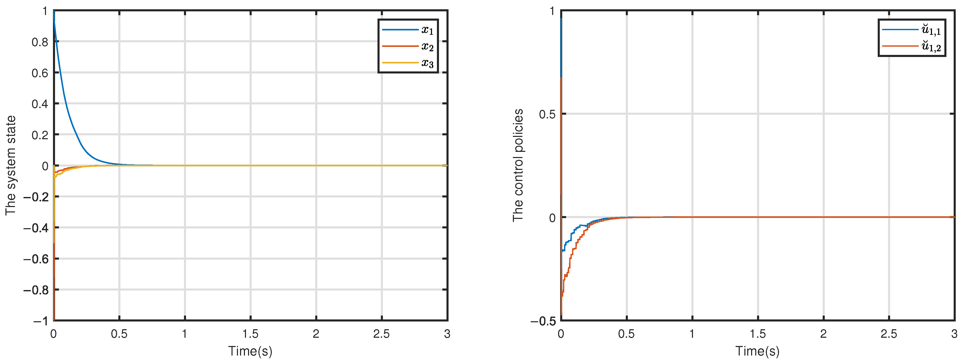
Figure 2a shows the convergence process of the system states ω ˜ , i ˜ q , i ˜ d , achieving rapid convergence to the zero-neighborhood within 0.5 s. The steady state errors are 1.749 × 10 6 rad / s , 5.419 × 10 9 A and 1.406 × 10 7 A , respectively. In particular, the angular velocity error ω ˜ decays to the order of 10 6 within the initial 0.2 s, confirming the reconfigured error model’s robustness against load disturbances.
The curves of u s q and u s d are illustrated in Figure 2b, where the control input amplitude is large in the initial stage to quickly suppress the state error. As the system approaches steady state, the control amount gradually decays to 0.366   μ V and 0.756   μ V , avoiding the current harmonics and energy loss caused by continuous high-frequency switching in traditional PI control.
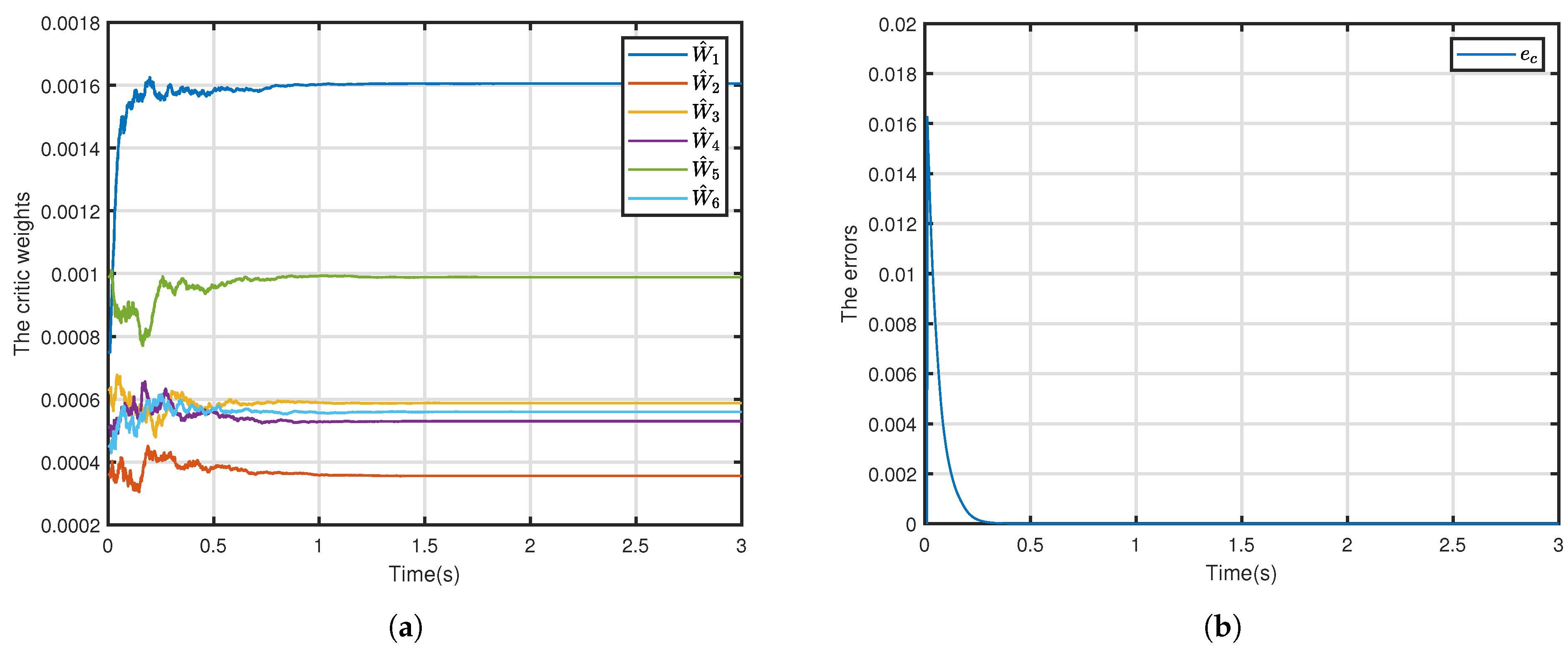
The convergence process of the critic NN weights W ^ 1 W ^ 6 is shown in Figure 3a, with steady state values of 0.0016 , 0.0004 , 0.0006 , 0.0005 , 0.0010 , 0.0006 , with the fluctuation amplitude always lower than 6 × 10 4 . The approximate Hamiltonian e c shown in Figure 3b indicates that the approximation accuracy of the critic network to the HJI equation has a maximum transient error e c max = 0.015 within the initial 0.1 s, followed by a rapid decay below 1.2 × 10 4 .
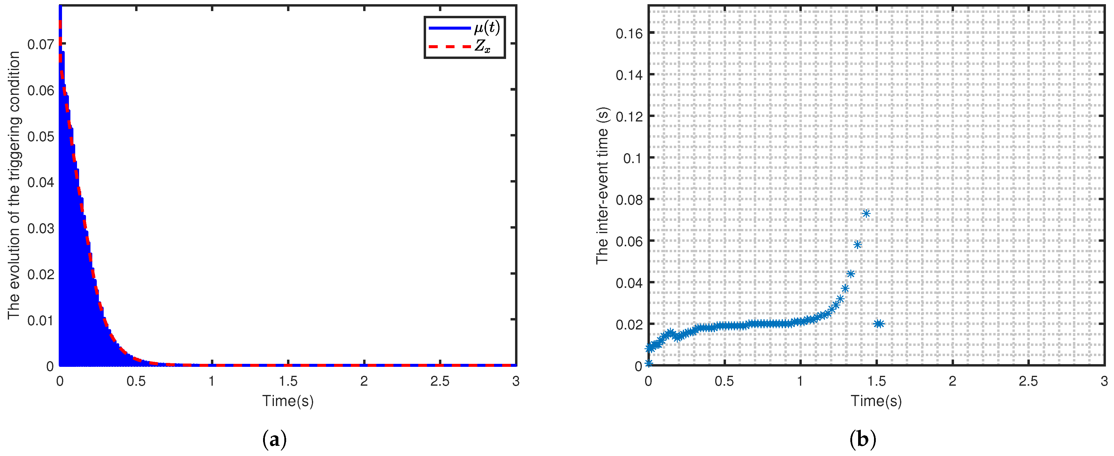
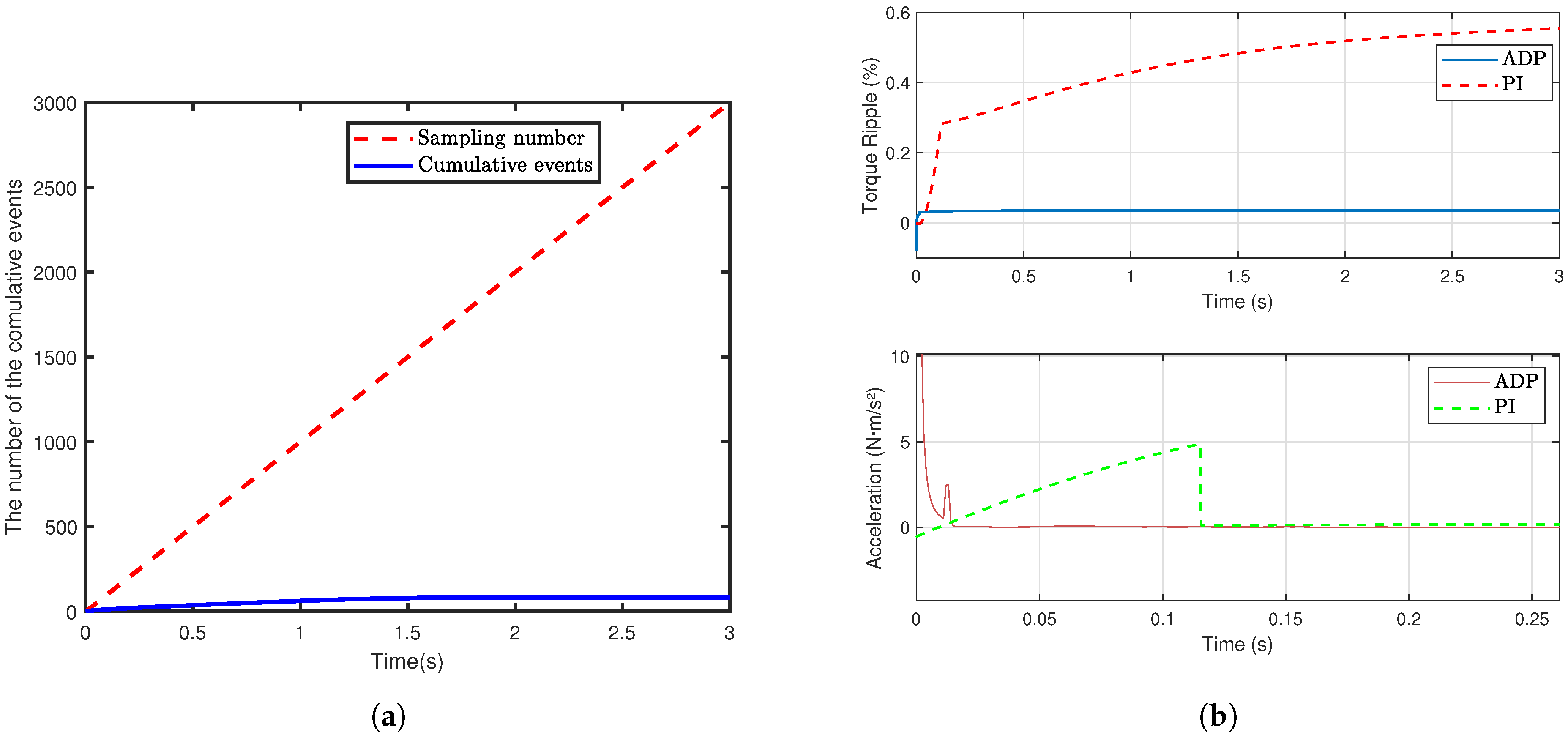
The performance of the event-triggering mechanism is evaluated by combining Figure 4. With the sensitivity parameter α = 0.1 , Figure 4a shows the relationship between the state error norm z x and the dynamic threshold μ ( t ) , both converging to zero as time increases. Figure 4b reveals the evolution of the event interval time. The minimum value of the trigger interval is 0.008 s in the initial stage. Then, it gradually increases until the system enters the dead zone and is no longer triggered. The trigger interval is always rigorously greater than zero throughout the whole process and maintains a significant safety margin after entering the steady state. In Figure 5a, the event trigger mechanism samples only 80 times, which reduces the computational load by 97.3% compared to 3001 samples of the time trigger mechanism. The mechanism is efficiently regulated by dynamic threshold design, which adaptively adjusts the trigger condition when the state norm x > 2 × 10 6 ; and switches to the deadband mode when x 2 × 10 6 to further suppress redundant events.
To comprehensively evaluate the effectiveness of the algorithm proposed in this work, three key performance indicators are introduced: torque ripple, total harmonic distortion (THD) of the q axis current, and vibration acceleration. These indicators are used to measure the steady-state stability of the system, the quality of the current waveform, and the level of mechanical vibration, respectively. The formulas for calculating these indicators are as follows
Torque Ripple = max ( T e ) min ( T e ) mean ( | T e | ) × 100 % ,
THD = n = 2 N V n 2 V 1 × 100 % ,
Vibration RMS = 1 N i = 1 N d T e d t 2 ,
where T e is the electromagnetic torque, V 1 is the amplitude of the fundamental component, V n are the amplitudes of the harmonic components, and d T e d t is the torque acceleration.
To further illustrate the advantages, a comparative experiment was conducted using an industrial-grade dual-loop PI controller as the baseline. The key parameters include speed loop proportional-integral gain of K p ω = 0.05 , K i ω = 0.2 ; current loop proportional–integral gain of K p i = 3 , K i i = 40 ; current limit of ± 5 A , and voltage limit of ± 20 V . Under the same motor model and operating conditions, the comparison results of the two controllers are shown in Figure 5b and Figure 6, and Table 3.
The results show that the torque ripple, THD of q axis current, and the vibration acceleration of the PI controller have higher values and it takes longer to reach steady state. In contrast, the event-triggered ADP controller proposed in this work suppresses torque ripple, THD of the q axis current, and vibration acceleration to extremely low levels through adaptive weight updating and H robust terms, demonstrating its significant advantages in high-precision PMSM drives.
To assess the feasibility of the algorithm proposed in this work in actual embedded systems, the core computational part of the algorithm was timed in the MATLAB environment, with a focus on measuring the time required for two key operations: online weight updating and gradient calculation.
The results show that the average time required for online weight updates is 1.4 µs, and the average time required for gradient calculations is 3.2 µs. Considering that the MATLAB R2022a runtime environment differs significantly from actual embedded systems such as the TI-C2000 DSP manufactured by Texas Instruments Inc. (Dallas, TX, USA) and STM32 microcontrollers supplied by STMicroelectronics N.V. (Plan-les-Ouates, Geneva, Switzerland), and that embedded systems may be subject to interference from other interruptions and tasks during runtime, leading to additional execution time. By scaling the MATLAB timing results by a factor of 10, the estimated execution time for online weight updates in actual embedded systems is 14 µs, gradient calculations take 32 µs, and the total execution time is 46 µs. The total execution time of the algorithm remains far below the common 1 kHz control cycle (1 ms), indicating that the algorithm has extremely high real-time feasibility in actual embedded systems.

4.3. Robustness Analysis

4.3.1. Robustness Analysis Against Step Disturbance

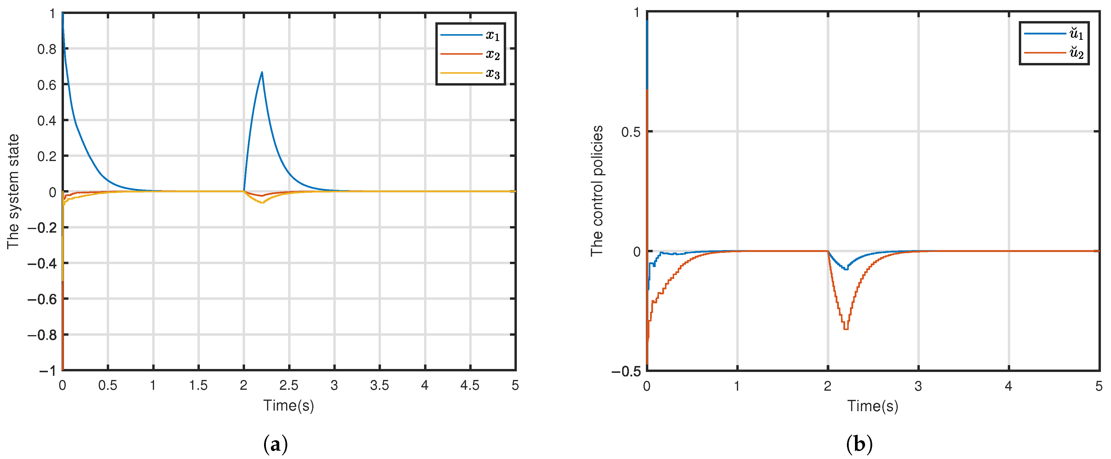
In order to evaluate the robustness of the ADP-based event-triggered H control algorithm proposed in this work, an additional step disturbance lasting 0.2 s is injected into the load torque at t = 2 s. The robustness of the system is analyzed through the dynamic response of the state variables, control inputs, and approximate Hamiltonian.
The state traces in Figure 7a show significant immunity to external disturbances. After injecting a disturbance at t = 2 s, the angular velocity error ω ˜ suddenly increases to 0.7 rad / s , reflecting the direct effect of the applied disturbance. However, the controller proposed in this work is able to suppress this deviation quickly, so ω ˜ is restored to the 10 6 level of accuracy in about 0.5 s. There is no oscillation phenomenon that may occur in traditional control methods.
The responses of u s q and u s d are shown in Figure 7b. After the injection of disturbance in t = 2 s , both u s q and u s d show a trend of first decreasing and then recovering. They both reach a minimum of 0.076 V and 0.327 V, respectively, at t = 2.2 s. Then, both control signals maintain their monotonic decay characteristics and return to a steady-state level close to zero around t = 3 s .
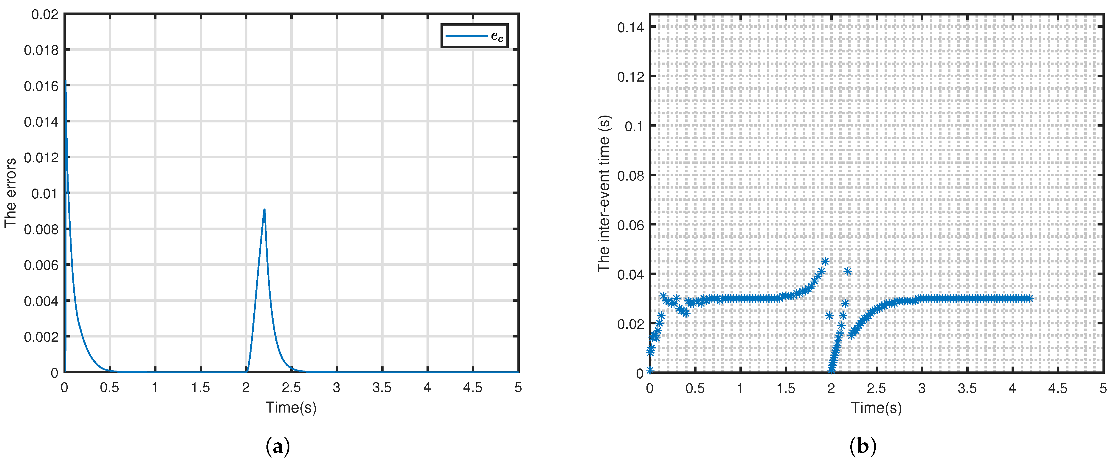
In Figure 8a, at the instant t = 2 s , the disturbance injection occurred. There are significant fluctuations in system error, where the approximate Hamiltonian increases rapidly to 9 × 10 3 . This error then exhibits a rapid decay characteristic and converges to a steady-state level close to zero around t = 2.6 s , returning to the pre-disturbance accuracy.
The above experimental results show that the proposed ADP-based event-triggered H control algorithm exhibits excellent robustness performance in dealing with step disturbances. The system is able to recover the angular velocity error to the order of 10 6 within 0.5 s , the Hamiltonian error converges to the near-zero steady state within 0.6 s , and the control signal always maintains a smooth decay characteristic. The inter-event time after an externally imposed disturbance is illustrated in Figure 8b. The controller achieves this robust performance while sampling only 169 times throughout the simulation, reducing the control updates by 96.6%, providing a more reliable solution for high-precision motor control.

4.3.2. Robustness Analysis Under Noise and Delay

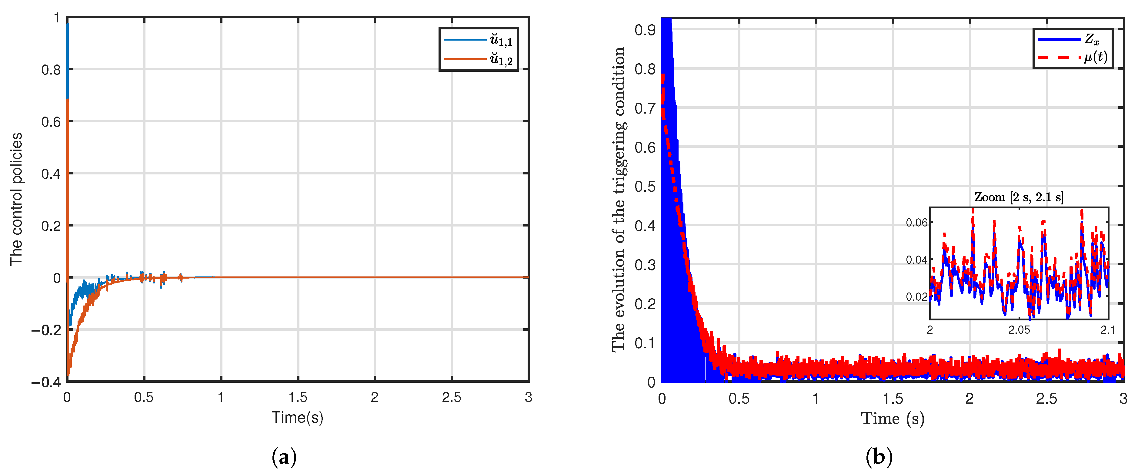
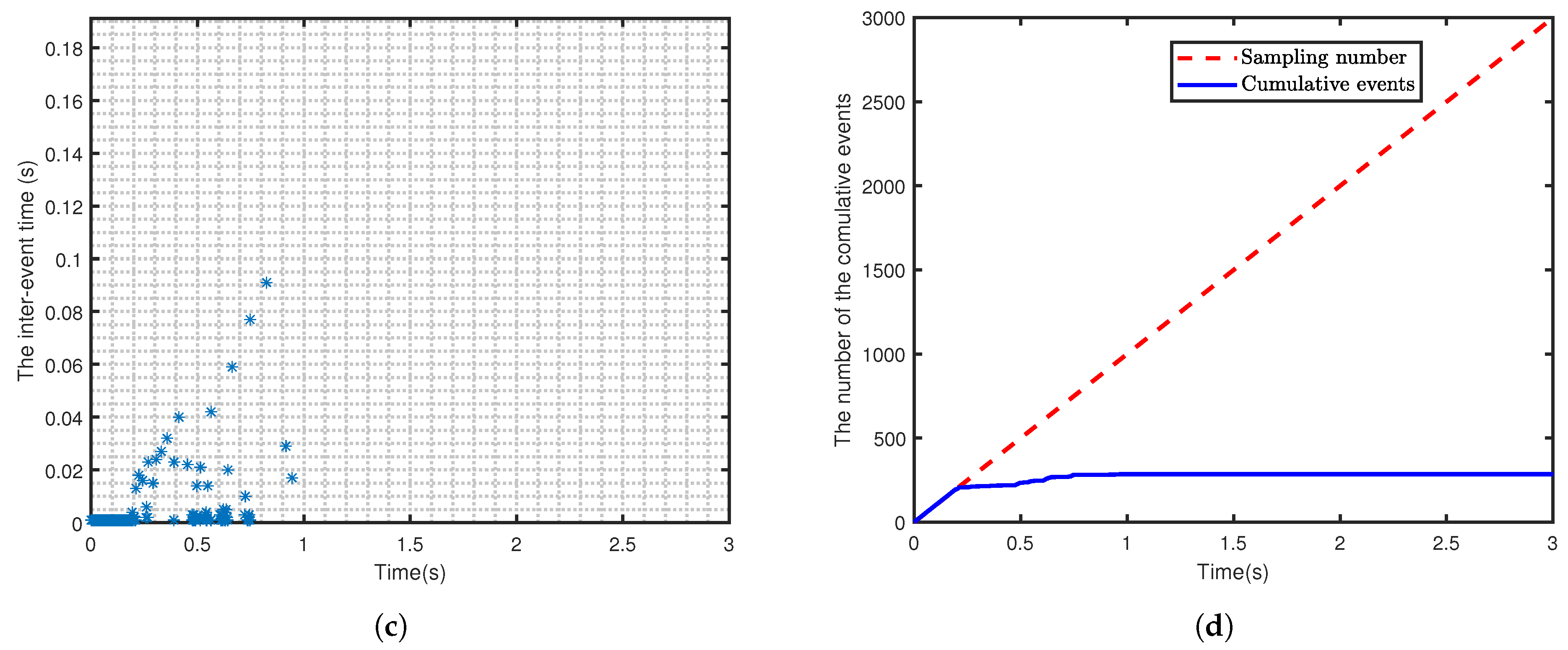
To verify the applicability of the method proposed in this work in actual embedded systems, the experiment introduced non-ideal conditions to simulate the real environment: Gaussian white noise with a mean of 0 and a standard deviation of 0.01 was added to the state measurements, and a fixed delay of 5 ms was applied to the control signal transmission.
Figure 9a shows that, compared to the ideal state, the waveforms of the control policies maintain the same convergence trend under non-ideal conditions, but periodic fluctuations of ± 0.05 V appear in the steady-state region. Figure 9b–d illustrates the operation of the event penalty mechanism under these non-ideal conditions. Compared to the ideal state, the number of event triggers has increased by several times, from 80 in the ideal state to 285. This indicates that noise and delay have a significant impact on the controller proposed in this work, increasing the computational burden on the system, but the system can still operate effectively. This demonstrates that the method proposed in this work also exhibits good robustness under non-ideal conditions.

5. Conclusions

In this work, an ADP-based event-triggered H control algorithm is applied to PMSM for the first time. The H control of PMSM is formulated as a two-player zero-sum differential game, which requires only a single critic network to approximate the solution of the HJI equation online, significantly simplifying the structure. The combination of feedforward compensation and the adaptive event-triggering mechanism effectively reduces the computational burden. It has been rigorously proven that both the system state x and the critic weight estimation error W ˜ are all UUB, and that the Zeno behavior is theoretically precluded. The simulation verifies that the method has high tracking accuracy and strong robustness under load disturbance and shock load, and the event-triggered mechanism reduces the amount of control updates by more than 96% compared to the time-triggered one, which provides a highly efficient and reliable control scheme for resource-constrained applications.

Author Contributions

Methodology, H.S. and W.Y.; Software, C.G. and W.Y.; Validation, H.S., W.Y. and Y.C.; Formal analysis, C.G. and Y.C.; Investigation, W.Y. and Y.C.; Writing—original draft, C.G.; Writing—review & editing, C.G. and H.S.; Visualization, C.G.; Supervision, H.S.; Project administration, H.S.; Funding acquisition, H.S. All authors have read and agreed to the published version of the manuscript.

Funding

This work was supported by National Natural Science Foundation of China (No. 62373091, 62103087, 62203311, 62473319 & U22A2055), China Postdoctoral Science Foundation (No. GZC20240227, 2024T170112, 2024M750373, 2023M740542 & 2021M690567), National Key R&D Program of China under grant 2018YFA0702200, the Fundamental Research Funds for the Central Universities (No. N25LPY031), Natural Science Foundation of Liaoning Province (No. 2023-MSBA-082), Natural Science Foundation of Shandong Province (No. ZR2024QF276), Natural Science Foundation of Guangdong Province (No. 2025A1515011504), Guangdong Basic and Applied Basic Research Foundation (No. 2023A1515110335), China Academy of Engineering institute of Land Cooperation Consulting Project (No. 2023-DFZD-60, 2023-DFZD-60-03) and Key Laboratory of Integrated Energy Optimization and Secure Operation of Liaoning Province.

Institutional Review Board Statement

Not applicable.

Informed Consent Statement

Not applicable.

Data Availability Statement

Data are contained within the article.

Conflicts of Interest

The authors declare no conflicts of interest.

References

  1. Nguyen, T.H.; Nguyen, T.T.; Nguyen, V.Q.; Le, K.M.; Tran, H.N.; Jeon, J.W. An Adaptive Sliding-Mode Controller with a Modified Reduced-Order Proportional Integral Observer for Speed Regulation of a Permanent Magnet Synchronous Motor. IEEE Trans. Ind. Electron. 2022, 69, 7181–7191. [Google Scholar] [CrossRef]
  2. Sanada, M.; Morimoto, S.; Takeda, Y. Interior Permanent Magnet Linear Synchronous Motor for High-Performance Drives. IEEE Trans. Ind. Appl. 1997, 33, 966–972. [Google Scholar] [CrossRef]
  3. Dhulipati, H.; Mukundan, S.; Li, Z.; Ghosh, E.; Tjong, J.; Kar, N.C. Torque Performance Enhancement in Consequent Pole PMSM Based on Magnet Pole Shape Optimization for Direct-Drive EV. IEEE Trans. Magn. 2021, 57, 8103407. [Google Scholar] [CrossRef]
  4. Liu, C.; Chau, K.T.; Lee, C.H.T.; Song, Z. A Critical Review of Advanced Electric Machines and Control Strategies for Electric Vehicles. Proc. IEEE 2020, 109, 1004–1028. [Google Scholar] [CrossRef]
  5. Ping, Z.; Wang, T.; Huang, Y.; Wang, H.; Lu, J.; Li, Y. Internal Model Control of PMSM Position Servo System: Theory and Experimental Results. IEEE Trans. Ind. Inf. 2020, 16, 2202–2211. [Google Scholar] [CrossRef]
  6. Liao, C.; Bianchi, N.; Zhang, Z. Recent Developments and Trends in High-Performance PMSM for Aeronautical Applications. Energies 2024, 17, 6199. [Google Scholar] [CrossRef]
  7. Niu, F.; Wang, B.; Babel, A.S.; Li, K.; Strangas, E.G. Comparative Evaluation of Direct Torque Control Strategies for Permanent Magnet Synchronous Machines. IEEE Trans. Power Electron. 2016, 31, 1408–1424. [Google Scholar] [CrossRef]
  8. Yu, Y.; Pan, Y.; Chen, Q.; Hu, Y.; Gao, J.; Zhao, Z.; Niu, S.; Zhou, S. Multi-Objective Optimization Strategy for Permanent Magnet Synchronous Motor Based on Combined Surrogate Model and Optimization Algorithm. Energies 2023, 16, 1630. [Google Scholar] [CrossRef]
  9. Fan, Z.-X.; Li, S.; Liu, R. ADP-Based Optimal Control for Systems with Mismatched Disturbances: A PMSM Application. IEEE Trans. Circuits Syst. II Express Briefs 2023, 70, 2057–2061. [Google Scholar] [CrossRef]
  10. Jung, J.; Leu, V.Q.; Do, T.D.; Kim, E.; Choi, H.H. Adaptive PID Speed Control Design for Permanent Magnet Synchronous Motor Drives. IEEE Trans. Power Electron. 2015, 30, 900–908. [Google Scholar] [CrossRef]
  11. Belkhier, Y.; Abdelyazid, A.; Oubelaid, A.; Khosravi, N.; Bajaj, M.; Vishnuram, P.; Zaitsev, I. Experimental Analysis of Passivity-Based Control Theory for Permanent Magnet Synchronous Motor Drive Fed by Grid Power. IET Control Theory Appl. 2024, 18, 495–510. [Google Scholar] [CrossRef]
  12. Soreshjani, M.H.; Heidari, R.; Ghafari, A. The Application of Classical Direct Torque and Flux Control (DTFC) for Line-Start Permanent Magnet Synchronous and Its Comparison with Permanent Magnet Synchronous Motor. J. Electr. Eng. Technol. 2014, 9, 1954–1959. [Google Scholar] [CrossRef]
  13. Nicola, M.; Nicola, C.-I.; Selișteanu, D.; Ionete, C.; Șendrescu, D. Improved Performance of the Permanent Magnet Synchronous Motor Sensorless Control System Based on Direct Torque Control Strategy and Sliding Mode Control Using Fractional Order and Fractal Dimension Calculus. Appl. Sci. 2024, 14, 8816. [Google Scholar] [CrossRef]
  14. Niu, F.; Huang, X.; Ge, L.; Zhang, J.; Wu, L.; Wang, Y. A Simple and Practical Duty Cycle Modulated Direct Torque Control for Permanent Magnet Synchronous Motors. IEEE Trans. Power Electron. 2018, 34, 1572–1579. [Google Scholar] [CrossRef]
  15. Fu, D.; Zhao, X.; Zhu, J. A Novel Robust Super-Twisting Nonsingular Terminal Sliding Mode Controller for Permanent Magnet Linear Synchronous Motors. IEEE Trans. Power Electron. 2021, 37, 2936–2945. [Google Scholar] [CrossRef]
  16. Qian, J.; Ji, C.; Pan, N.; Wu, J. Improved Sliding Mode Control for Permanent Magnet Synchronous Motor Speed Regulation System. Appl. Sci. 2018, 8, 2491. [Google Scholar] [CrossRef]
  17. Li, K.; Ding, J.; Sun, X.; Tian, X. Overview of Sliding Mode Control Technology for Permanent Magnet Synchronous Motor System. IEEE Access 2024, 12, 71685–71704. [Google Scholar] [CrossRef]
  18. Powell, W.B. Approximate Dynamic Programming: Solving the Curses of Dimensionality; John Wiley & Sons: Hoboken, NJ, USA, 2007. [Google Scholar]
  19. El-Sousy, F.F.M.; Amin, M.M.; Al-Durra, A. Adaptive Optimal Tracking Control via Actor-Critic-Identifier Based Adaptive Dynamic Programming for Permanent-Magnet Synchronous Motor Drive System. IEEE Trans. Ind. Appl. 2021, 57, 6577–6591. [Google Scholar] [CrossRef]
  20. Kiumarsi, B.; Lewis, F.L. Actor-Critic-Based Optimal Tracking for Partially Unknown Nonlinear Discrete-Time Systems. IEEE Trans. Neural Netw. Learn. Syst. 2015, 26, 140–151. [Google Scholar] [CrossRef] [PubMed]
  21. Vamvoudakis, K.G.; Lewis, F.L. Online Actor-Critic Algorithm to Solve the Continuous-Time Infinite Horizon Optimal Control Problem. Automatica 2010, 46, 878–888. [Google Scholar] [CrossRef]
  22. Khiabani, A.G.; Heydari, A. Optimal Torque Control of Permanent Magnet Synchronous Motors Using Adaptive Dynamic Programming. IET Power Electron. 2020, 13, 2442–2449. [Google Scholar] [CrossRef]
  23. Karg, P.; Köpf, F.; Braun, C.A.; Hohmann, S. Excitation for Adaptive Optimal Control of Nonlinear Systems in Differential Games. IEEE Trans. Autom. Control 2023, 68, 596–603. [Google Scholar] [CrossRef]
  24. Su, H.; Zhang, H.; Liang, Y.; Mu, Y. Online Event-Triggered Adaptive Critic Design for Non-Zero-Sum Games of Partially Unknown Networked Systems. Neurocomputing 2019, 368, 84–98. [Google Scholar] [CrossRef]
  25. Liang, Y.; Luo, Y.; Su, H.; Zhang, X.; Chang, H.; Zhang, J. Event-Triggered Explorized IRL-Based Decentralized Fault-Tolerant Guaranteed Cost Control for Interconnected Systems against Actuator Failures. Neurocomputing 2025, 615, 128837. [Google Scholar] [CrossRef]
  26. Zhong, X.; He, H. An Event-Triggered ADP Control Approach for Continuous-Time System with Unknown Internal States. IEEE Trans. Cybern. 2017, 47, 683–694. [Google Scholar] [CrossRef]
  27. Wang, D.; Mu, C.; He, H.; Liu, D. Event-Driven Adaptive Robust Control of Nonlinear Systems with Uncertainties through NDP Strategy. IEEE Trans. Syst. Man Cybern. Syst. 2017, 47, 1358–1370. [Google Scholar] [CrossRef]
  28. Sahoo, A.; Xu, H.; Jagannathan, S. Neural Network-Based Event-Triggered State Feedback Control of Nonlinear Continuous-Time Systems. IEEE Trans. Neural Netw. Learn. Syst. 2016, 27, 497–509. [Google Scholar] [CrossRef]
  29. Zhang, H.; Su, H.; Zhang, K.; Luo, Y. Event-Triggered Adaptive Dynamic Programming for Non-Zero-Sum Games of Unknown Nonlinear Systems via Generalized Fuzzy Hyperbolic Models. IEEE Trans. Fuzzy Syst. 2019, 27, 2202–2214. [Google Scholar] [CrossRef]
  30. Su, H.; Zhang, H.; Jiang, H.; Wen, Y. Decentralized Event-Triggered Adaptive Control of Discrete-Time Nonzero-Sum Games over Wireless Sensor-Actuator Networks with Input Constraints. IEEE Trans. Neural Netw. Learn. Syst. 2020, 31, 4254–4266. [Google Scholar] [CrossRef]
  31. Su, H.; Zhang, H.; Gao, D.W.; Luo, Y. Adaptive Dynamics Programming for H Control of Continuous-Time Unknown Nonlinear Systems via Generalized Fuzzy Hyperbolic Models. IEEE Trans. Syst. Man Cybern. Syst. 2019, 50, 3996–4008. [Google Scholar] [CrossRef]
  32. Dai, C.; Guo, T.; Yang, J.; Li, S. A Disturbance Observer-Based Current-Constrained Controller for Speed Regulation of PMSM Systems Subject to Unmatched Disturbances. IEEE Trans. Ind. Electron. 2021, 68, 767–775. [Google Scholar] [CrossRef]
Figure 1. Flowchart of the event-triggered ADP optimal control. Green rounded rectangles indicate the start and end points of the process. Blue rectangles are arranged in sequence and are used to initialise parameters, read statuses, update weights, calculate control quantities, and solve systems. Orange diamonds are located at branch points and are used to trigger conditional judgments that determine the direction of the process.
Machines 13 00715 g001
Figure 2. (a) System states. (b) Control policies.
Machines 13 00715 g002
Figure 3. (a) Critic weights. (b) Approximate Hamiltonian.
Machines 13 00715 g003
Figure 4. (a) Relationship between the event-triggered error and the triggering threshold. (b) Triggering instants for system. The horizontal axis of Blue Star represents the moment when the event is triggered, and the vertical axis represents the triggering instants.
Machines 13 00715 g004
Figure 5. (a) Cumulative events for system. (b) Comparison of torque ripple and vibration acceleration with ADP and PI controllers.
Machines 13 00715 g005
Figure 6. (a) Q axis current harmonic spectrum of ADP controller. (b) Q axis current harmonic spectrum of PI controller.
Machines 13 00715 g006
Figure 7. (a) System states after an externally imposed disturbance. (b) Control policies after an externally imposed disturbance.
Machines 13 00715 g007
Figure 8. (a) Approximate Hamiltonian after an externally imposed disturbance. (b) Triggering instants for system after an externally imposed disturbance.
Machines 13 00715 g008
Figure 9. (a) Control policies under noise and delay. (b) Relationship between the event-triggered error and the triggering threshold under noise and delay. (c) Triggering instants for the system under noise and delay. The horizontal axis of Blue Star represents the moment when the event is triggered, and the vertical axis represents the triggering instants. (d) Cumulative events for system under noise and delay.
Machines 13 00715 g009aMachines 13 00715 g009b
Table 2. Performance metrics for different learning rates.
Learning RateSteady-State ErrorConvergence Time (s)
0.0001 2.81 × 10 19 1.505
0.001 1.36 × 10 25 1.169
0.01 2.02 × 10 23 1.256
0.1 4.51 × 10 21 1.457
1.0 2.04 × 10 15 1.863
2.0 4.59 × 10 11 2.666
5.0 5.03 × 10 22 1.305
Table 3. Performance comparison results between ADP controller and PI controller.
Control StrategyTorque Ripple (%)THD (iq) (%)Vibration RMS
ADP0.0350.03 7 × 10 9
PI0.55333.34 8.16 × 10 4
Disclaimer/Publisher’s Note: The statements, opinions and data contained in all publications are solely those of the individual author(s) and contributor(s) and not of MDPI and/or the editor(s). MDPI and/or the editor(s) disclaim responsibility for any injury to people or property resulting from any ideas, methods, instructions or products referred to in the content.