Abstract
In the practical physical structure of the electromagnetic inerter–spring–damper (EM–ISD) suspension, parasitic damping inevitably coexists with the mechanical inerter effect. To investigate the intrinsic influence of this parasitic effect on the suspension system’s performance, this study first establishes a quarter-vehicle dynamic model that incorporates parasitic damping, based on the actual configuration of the EM–ISD suspension. Subsequently, the particle swarm optimization (PSO) algorithm is employed to optimize the key suspension parameters, with the objective of enhancing its comprehensive performance. The optimized parameters are then utilized to systematically analyze the dynamic characteristics of the suspension under the influence of parasitic damping. The results indicate that, compared to an ideal model that neglects parasitic damping, an increase in the parasitic damping coefficient leads to a deterioration in the root mean square (RMS) value of body acceleration, while concurrently reducing the RMS values of the suspension working space and dynamic tire load. However, by incorporating parasitic damping into the design considerations during the optimization phase, its adverse impact on ride comfort can be effectively mitigated. Compared with a traditional passive suspension, the optimized EM–ISD suspension, which accounts for parasitic damping, demonstrates superior performance. Specifically, the RMS values of body acceleration and suspension working space are significantly reduced by 11.1% and 17.6%, respectively, thereby effectively improving the vehicle’s ride comfort and handling stability.
1. Introduction
In recent years, the rapid development of lightweight manufacturing technology and advanced forming processes has established new paradigms for systematic optimization design in the field of vehicle engineering [1,2,3]. These technological advancements have enabled the fabrication of mechanical components with more complex geometric configurations and superior mechanical properties [4,5,6,7], thereby laying a critical foundation for the structural innovation and performance enhancement of suspension systems.
As a crucial component of vehicle vertical motion, the suspension is of great significance to ride comfort. Current research on suspension systems primarily encompasses three main areas: structural design [8,9], control strategies [10,11,12], and actuator development [13].
To overcome the inherent dynamic limitations constraining traditional passive suspensions, academia and industry have focused on the innovative methods, theories, and technologies in suspension design. Extensive research efforts have been dedicated to overcoming the inherent dynamic limitations of suspension systems through semi-active control and active control, resulting in the development of various innovative suspension design theories and methods. Xu et al. [14] proposed a novel semi-active quasi-zero-stiffness air suspension with H2/H∞ robust control for commercial vehicles, significantly enhancing multi-objective comprehensive performance under complex driving conditions. Savaresi et al. [15] proposed an acceleration-driven damper (ADD) control for semi-active suspensions, optimizing comfort by minimizing vertical body acceleration without a road preview. It offers simplicity comparable to skyhook control, with superior performance validated through theoretical and numerical analyses. Morselli et al. [16] proposed four novel control laws for dissipative components within the Port-Hamiltonian framework, enabling control objectives by managing subsystem energy or power flow, with feasibility demonstrated in semi-active suspension applications. Furthermore, Zhao et al. [17] proposed a semi-active seat suspension with a tunable electromagnetic damper (EMD) and a prescribed performance control strategy for force tracking. Experimental validation across various vibration conditions shows significant reductions in acceleration metrics compared to a passive system, enhancing ride comfort. Shen et al. [18] introduced the inerter element into the vehicle air suspension and investigated the dynamic behavior of the semi-active vehicle air ISD (inerter–spring–damper) suspension, optimized via a genetic algorithm, which significantly improves ride comfort, handling stability, and driving safety over conventional systems. Chen et al. [19] investigated an electric control air suspension system for agricultural transport vehicles, proposing a single-neuron adaptive PID controller to enhance stability and ride comfort. Cui et al. [20] performed a parameter optimization for a large spray boom suspension by combining rigid–flexible coupling modeling with a multi-objective genetic algorithm. Cui et al. [21] introduced and validated an active suspension control strategy for boom sprayers, using simulator and field tests to demonstrate its effectiveness in reducing roll disturbances and tracking low-frequency terrain changes. Shen et al. [22] proposed a design method for a mechatronic ISD suspension using a fractional-order biquadratic transfer function to overcome the performance limitations of traditional integer-order systems.
With the advent of the inerter [23], the traditional vibration isolation theory based on the “mass–spring–damper” model has been further advanced. Relevant vibration suppression devices and corresponding theories have emerged continuously [24], appearing in the form of an “inerter–spring–damper” vibration isolation system, which further enriches the design theory of vehicle suspension. The vehicle suspension that adopts the “inerter–spring–damper” vibration isolation system is called inerter–spring–damper (ISD) suspension, also called inertial suspension, typically comprising at least one inerter, a spring, and a damper element. Due to their substantial potential for enhancing vibration isolation performance, many scholars have conducted research on it [25]. Shen et al. utilized the characteristics of an inerter as a bidirectional endpoint component and successfully developed a novel inertial apparatus by replacing the conventional mass element-based dynamic vibration absorber. This innovation significantly weakened the vibration of the vehicle body at the offset frequency. Yang et al. [26] proposed a structure-based compensation approach for control phase deviation in semi-active inertial suspensions through complex-domain mechanical impedance analysis, and experimentally validated that the coordinated inertial suspension structure significantly enhances comprehensive performance. Liu et al. [27] investigated the road-friendliness of heavy vehicles under three different suspension layouts and demonstrated that integrating an inerter into the suspension system could markedly decrease road surface damage. Furthermore, Li et al. [28] proposed a two-stage ISD suspension system and substantiated its capability to significantly enhance overall vehicle ride comfort. Shen et al. [29] confirmed that the proposed fractional-order SH–GH ISD suspension with adaptive control reduces RMS body acceleration and tire load more effectively than integer-order and passive systems under both sinusoidal and random road excitations.
As research progresses, the structural layout of suspension systems has increasingly trended toward complexity, with a corresponding rise in their impedance order. Studies have demonstrated that suspension systems exhibiting higher-order impedance properties display superior vibration isolation performance. However, an overly high impedance order leads to greater complexity in the structural layout of suspension systems. Furthermore, constrained by the limited space of the vehicle chassis, it becomes challenging to implement such complex structures. Consequently, the practical implementation of these complex suspension structures has emerged as a pressing technical challenge that requires urgent resolution. In 2011, a suspension system design methodology grounded in the mechatronic network strut was introduced [30]. This theoretical framework has facilitated both structural innovation in inerters [31] and the development of their systematic optimization design architecture [32,33]. Research has demonstrated that such innovative designs can significantly reduce the structural complexity of ISD suspensions. According to Pantell [34] simplification, non-series-parallel networks can achieve higher impedance functions with fewer components. Wang et al. [35] studied biquadratic impedance and bicubic impedance using bridge networks and also provided the realization conditions of them. As a representative implementation within this framework, the electromagnetic inerter integrates fluid inerter [36] mechanisms with linear motor systems, forming a novel electromechanically coupled device with multifunctional capabilities. Its innovation is manifested in two dimensions: mechanically, it achieves the series characteristics of damper and inerter; electrically, it can simulate more complex suspension layouts through external circuits. This mechatronic approach decouples the physical mechanical structure from the desired dynamic behavior, offering a pathway to achieve high-order performance without corresponding mechanical complexity. Based on this technology, the developed vehicle suspension system is formally defined as an electromagnetic inerter–spring–damper suspension (EM–ISD suspension).
For the application of the electromagnetic inerter in vehicle suspension, previous studies have demonstrated that a mechanical damper and inerter in series have greater vibration suppression potential [37], while also conducting detailed analyses of the nonlinear characteristics of motor parameters in the EM–ISD suspension. However, these studies have not adequately considered the effect of parasitic damping generated by fluid flow through the external spiral tube. This parasitic damping is in parallel with the mechanical inerter. This paper focuses on this issue, investigating the impact of parasitic damping on suspension performance and providing a theoretical foundation for the engineering application of the EM–ISD suspension.
This paper is arranged as follows. In Section 2, an EM–ISD suspension quarter model considering parasitic damping is constructed. In Section 3, the particle swarm optimization algorithm is used to optimize the suspension system parameters. In Section 4, the influence of the variation in the parasitic damping coefficient on the performance index of suspension is analyzed. In Section 5, the suspension parameters are optimized and the performance indexes are analyzed under the consideration of parasitic damping. Section 6 draws some conclusions.
2. Dynamic Model of Vehicle EM–ISD Suspension
2.1. The Structure and Principle of the Electromagnetic Inerter
The EM–ISD suspension proposed in this study employs an electromagnetic inerter system, as depicted in Figure 1a. This system comprises two synergistic subsystems: an electromagnetic subsystem realized through a linear motor (Figure 1b) and a liquid subsystem constructed with the fluid inerter (Figure 1c) [38,39]. The electromagnetic subsystem (Figure 1b) includes the winding (shown in red), permanent magnet (in dark gray), flux ring (in light gray), and primary core (in gray), while the liquid subsystem (Figure 1c) features the helical tube (in orange), piston rod (in light gray), piston (in blue), damping hole (in black), and air chamber (in transparent).Compared with other types of mechanical inerter, the fluid inerter can achieve a series configuration between damper and inerter with enhanced energy dissipation efficiency. In this series configuration, when the piston rod undergoes vertical motion, the fluid sequentially passes through the helical tube (generating the mechanical response characteristics of the inerter) followed by the damping hole (producing the damping characteristics). The force–velocity conversion based on the electromechanical analogy theory is accomplished by a linear motor operating in power generation mode. Different suspension layouts can be simulated by changing the external circuit of the linear motor.
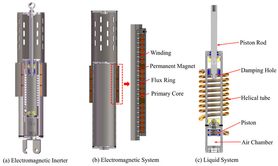
Figure 1.
Electromagnetic inerter and its mode of implementation.
2.2. Vehicle EM–ISD Suspension Model
Based on the analysis presented, the quarter model of the EM–ISD suspension is illustrated in Figure 2. The suspension system is composed of two primary subsystems: a mechanical network and an electrical network.
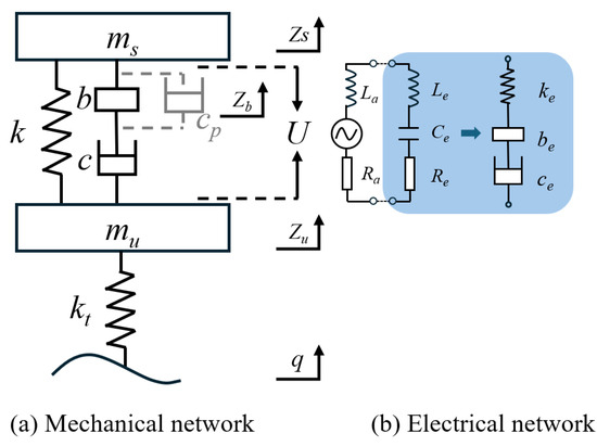
Figure 2.
The quarter model of EM–ISD suspension.
The mechanical network incorporates an electromagnetic inerter, characterized by the parameters b, c, and cp, where b denotes the inertance, c represents the damping coefficient, and cp signifies the parasitic damping. The network further includes the sprung mass ms, the unsprung mass mu, the spring stiffness k, and the tire stiffness kt. Zs, Zb, Zu, and q represent the sprung mass, electromagnetic inerter, unsprung mass, and vertical displacement of the road surface, respectively.
The electrical network is depicted in blue in Figure 2. The black dashed line represents the generation of the terminal voltage U by the linear motor through vertical vibrations of the suspension, serving as the power source for the external circuit. The armature resistance Ra and armature inductance La correspond to the internal resistance and inductance of the motor, respectively. Additionally, the external circuit comprises a resistor Re, an inductor Le, and a capacitor Ce, which collectively constitute the electrical components of the system. These elements are designed to emulate the mechanical counterparts in the suspension system, specifically the equivalent damping Ce, the equivalent spring stiffness ke, and the equivalent inertance be, respectively.
The dynamic equation for this suspension model is given by
Given that the primary focus of this study is to analyze the impact of parasitic resistance on the performance of the EM–ISD, and considering that the external circuit solely serves the purpose of implementing control functions (where the influence of its internal resistance and inductance is negligible), the armature resistance and inductance of the linear motor are therefore neglected. When the suspension system is subjected to road roughness excitation, a relative velocity arises between the two endpoints of the EM–ISD device. Consequently, the generated electromagnetic force can be expressed as
In the equation, is the Laplace transform of the force exerted by the linear motor on the endpoints of the EM–ISD device. and are the Laplace transforms of the vertical displacement of the sprung mass and the vertical displacement of the lower endpoint of the inerter, respectively. represents the impedance of the external circuit, and its expression, based on the series connections of the circuit components, is given by
The road condition adopted in this paper is the C-level random excitation described in reference [37], which can be described by the following equation:
where q(t) is the road input, f0 is the cut-off frequency, G0 is the road roughness coefficient, v is the vehicle speed, and w(t) is the random white noise with zero mean. The underlying parameters of the road model are shown in Table 1.

Table 1.
Parameters of road model.
3. Parameter Optimization
In this study, the classic particle swarm optimization (PSO) algorithm [40,41] is employed to obtain the optimal parameters for the EM–ISD suspension system. The algorithm has the advantages of simple calculation and fast convergence speed and is especially suitable for multi-parameter coupled optimization problems. This advantage is critical for the current study, as the EM–ISD suspension optimization involves five key parameters (b, c, be, ce, ke) that are intricately coupled and influence the complex dynamic response of the quarter-vehicle model under random excitation. Furthermore, the optimization objective requires minimizing body acceleration while constraining suspension working space and dynamic tire load, representing a problem with potential local minima. PSO uses individual cognition and global information sharing to find the optimal solution by simulating the behavior of biological groups. Following particle swarm initialization, the velocity and position of each particle are iteratively updated through fitness evaluation until the termination criteria are satisfied. The flowchart of the algorithm is shown in Figure 3. The parameter settings of the PSO algorithm are shown in Table 2.
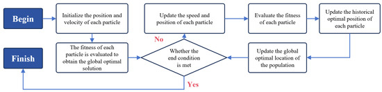
Figure 3.
Flow chart of particle swarm optimization algorithm.
Table 2.
Parameter settings of the PSO algorithm.
The optimization objectives are as follows:
RMS(BAEM–ISD), RMS(SWSEM–ISD), and RMS(DTLEM–ISD) represent the root mean square (RMS) values of the body acceleration, suspension working space, and dynamic tire load, respectively, for the EM–ISD suspension. RMS(DTLPA) and RMS(SWSPA) represent the RMS values of the dynamic tire load and suspension working space, respectively, for the traditional passive suspension. In the optimization process of EM–ISD suspension, the RMS of body acceleration, dynamic tire load, and suspension working space are used as the evaluation indexes. The reduction in the RMS of body acceleration is set as the primary goal, and it is necessary to ensure that the RMS of dynamic tire load and the RMS of suspension dynamic travel are not higher than that of traditional passive suspension.
The five parameters b, c, be, ce, and ke are the optimization parameters for the EM–ISD suspension, while the other parameters k, kt, ms, and mu remain consistent with those of the traditional passive suspension. The specific parameters of the traditional passive suspension are shown in Table 3. The parameters are taken from reference [37].
Table 3.
Basic parameters of traditional passive suspension.
4. Effect of Parasitic Damping on EM–ISD Suspension
Parasitic damping is a critical determinant influencing the performance of the electromagnetic inerter. In order to investigate the influence law of parasitic damping on the EM–ISD suspension, assuming that there is no parasitic damping force in the helical tube of the fluid inerter in the EM–ISD suspension, the RMS(BAEM–ISD), RMS(SWSEM–ISD), and RMS(DTLEM–ISD) are 1.63 m/s2, 14.98 mm, and 1088.87 N, respectively, using the PSO optimization described in Section 3. Compared with the traditional passive suspension, the acceleration reduction of the body reaches 17.81%. The specific values are shown in Table 4 and Table 5.
Table 4.
Optimized EM–ISD suspension parameters without parasitic damping.
Table 5.
Performance comparison without parasitic damping.
Based on this, parasitic damping was introduced into the reference condition, with the parasitic damping coefficient cp set to a range of 200–4000 N·s·m−1. The PSO algorithm was then reapplied, and the resulting optimization outcomes are presented as the black curve in Figure 4, which represents the performance change of the EM–ISD suspension when the parameters shown in Table 4 are kept in the ideal state and only the additional parasitic damping coefficient is added. Analyzing the black curve in Figure 4a shows that a significant nonlinear relationship between RMS(BAEM–ISD) and parasitic damping coefficient cp. When cp increases from 200 to 4000 N·s·m−1, RMS(BAEM–ISD) rises from 1.64 to 1.75 m/s2. This result demonstrates that cp plays a critical role in the system’s vibration response, and its influence on dynamic characteristics cannot be neglected. In contrast, the trends displayed by the black curves in Figure 4b, c are opposite: an increase in cp leads to a decreasing trend in both RMS(SWSEM–ISD) and RMS(DTLEM–ISD). From the overall change magnitude of the three graphs, this proves that the law of mutual restriction among the body acceleration, suspension working space, and dynamic tire load exists in the EM–ISD suspension system. Specifically, when one of the three parameters changes, the other two usually change in opposite directions. This mutual restriction relationship is closely related to the research core of this paper: how to reduce the body acceleration as much as possible under the influence of parasitic damping, while ensuring that the suspension working space and dynamic tire load do not exceed the corresponding index of the passive suspension.
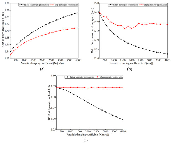
Figure 4.
Effect of parasitic damping force on suspension performance: (a) RMS of body acceleration; (b) RMS of suspension working space; (c) RMS of dynamic tire load.
Therefore, for parasitic damping coefficients cp varied in steps of 250, the optimized suspension performance of the electromagnetic inertial system, obtained using the PSO algorithm, is depicted by the red curve in Figure 4. By tracking the change in the damping coefficient in real time, the algorithm continuously updated the optimal suspension parameter configuration, so as to ensure that the system always maintained the best body acceleration suppression performance in the whole working range.
As shown by the red curve in Figure 4a, after EM–ISD suspension parameter optimization, RMS(BAEM–ISD) still exhibits a monotonically increasing trend with the rise of cp, but both its growth rate and amplitude are significantly reduced compared to before parameter optimization (black curve). When cp increases from 200 to 4000 N·s·m−1, RMS(BAEM–ISD) rises from 1.64 to 1.71 m/s2, representing a 36% reduction in growth amplitude compared to before parameter optimization. Meanwhile, the red curves in Figure 4b,c illustrate that, despite relaxing the constraint boundaries of RMS(SWSEM–ISD) and RMS(DTLEM–ISD) to passive suspension benchmarks, their performance remains effectively controlled within engineering-acceptable limits; RMS(SWSEM–ISD) stabilizes between 13.5–14.0 mm, achieving an 11.67–14.8% reduction compared to the passive suspension benchmark (15.85 mm); and RMS(DTLEM–ISD) remains constant at 1.088 KN across the entire cp range (fluctuation: ±0.002 KN).
Therefore, in view of the influence of parasitic damping force, the reasonable adjustment of the equivalent damping coefficient and inertance coefficient can effectively reduce the body vibration response caused by the parasitic damping force and maintain good suspension working space and dynamic tire load. By comparing the performance of the traditional passive suspension, the optimized EM–ISD suspension has significant advantages in vehicle ride comfort, which lays a foundation for further engineering applications of the suspension system.
5. Performance Analysis of EM–ISD Suspension Considering Parasitic Damping
For the parasitic damping force of the fluid inerter, the relevant formula has been given in the literature [36]:
where ρ is the fluid density, μ is the dynamic viscosity of the fluid, A1 is the effective cross-sectional area of the main cylinder, A2 is the cross-sectional area of the helical tube, Dh is the diameter of the helical tube, R is the rotation radius of the helical tube, ℓ is the total length of the helical tube, and is the moving speed of the piston.
Inertance coefficient b is calculated according to the formula in reference [42]:
where h is the pitch of the helical tube, and the meaning of the remaining variables is consistent with Formula (6). From the point of view of establishing the correlation between inertance coefficient and parasitic damping force, the original optimization parameter b is replaced with three parameters: number of turns n of the helical tube, rotational radius R of the helical tube, and pitch h of the helical tube, which determine the helical tube length ℓ, as shown below [42]:
Based on the theoretical framework after parameter optimization (red curve) described in Section 4, this study converts the mechanical inertance coefficient b into specific design parameters of the EM–ISD system using Equations (7) and (8), and uses Equation (6) to represent the value of in Equation (1), followed by a renewed PSO calculation. The optimized key parameters of the EM–ISD suspension system are detailed in Table 6. It should be noted that although both the effective cross-sectional area of the main cylinder and the cross-sectional area of the helical tube influence the value of inertance coefficient b, the main cylinder diameter is constrained to 40 mm, the piston rod diameter is specified as 14 mm, and the helical tube inner diameter is set at 8 mm due to the installation dimensional constraints of the suspension system, with these geometric parameters determined based on practical engineering assembly requirements.
Table 6.
Optimized EM–ISD suspension parameters with parasitic damping.
Based on the suspension parameters in Table 6, the dynamic changes of the body acceleration, suspension working space, and dynamic tire load under random road excitation, as shown in Figure 5, can be obtained. From this, the RMS(BA), RMS(SWS), and RMS(DTL) of EM–ISD suspension and traditional passive suspension listed in Table 7 can be obtained.
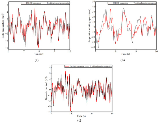
Figure 5.
Dynamic performance of vehicle suspension under random road surface: (a) body acceleration; (b) suspension working space; (c) dynamic tire load.
Table 7.
Performance comparison with parasitic damping.
From a numerical point of view, the RMS(DTL) of the EM–ISD suspension is not significantly different from that of traditional passive suspension, and the RMS(SWS) of the EM–ISD suspension is reduced by 17.6%. In terms of RMS(BA), the EM–ISD suspension can achieve a reduction of 11.1%. The simulation results demonstrate good consistency with the theoretical analysis presented in Section 4, which validates the necessity of introducing parasitic damping force constraints in the suspension parameter optimization model. Computational analysis reveals that systematic quantification of parasitic damping effects can reduce the body acceleration, while maintaining suspension working space and dynamic tire load within acceptable thresholds.
From the power spectral density (PSD) analysis results, Figure 6 clearly shows the frequency response characteristics of body acceleration, suspension working space, and dynamic tire load. It can be seen from the figure that EM–ISD suspension has an outstanding vibration suppression effect in the frequency range of 1–2 Hz, which significantly reduces the power spectral density of these three indexes. This frequency interval corresponds to the low-frequency resonance region of the vehicle body, which is a key factor affecting the ride comfort of the vehicle. The vibration transmission of traditional passive suspension is obvious in this frequency range, which easily causes body resonance and results in the increased fatigue of the occupant. By introducing the coordination between mechanical inerter and parasitic damping, EM–ISD suspension can significantly inhibit the transmission of offset frequency vibration, and effectively improve the vibration response characteristics of the body.
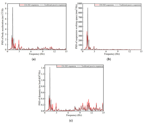
Figure 6.
Power spectral density: (a) PSD of body acceleration; (b) PSD of suspension working space; (c) PSD of dynamic tire load.
6. Conclusions
Parasitic damping in the electromagnetic inerter is one of the key factors determining the upper limit of the comfort performance of EM–ISD suspension. With the increase in the parasitic damping coefficient, the RMS(BAEM–ISD) will gradually increase regardless of whether this factor is considered in the optimization process. However, if parasitic damping is considered in the optimization and RMS(SWSEM–ISD) and RMS(DTLEM–ISD) are set as the boundaries of the optimization objective, the rising trend of RMS(BAEM–ISD) can be effectively suppressed. After establishing the EM–ISD suspension model, which is related to the inertance and parasitic damping coefficient, a set of EM–ISD suspension parameters that take into account the inertance and parasitic damping generated in the helical tube is obtained. It achieved 11.1% and 17.6% reductions in RMS(BA) and RMS(SWS) compared to conventional passive suspension, demonstrating excellent vibration isolation performance at the body offsets frequency.
Author Contributions
Conceptualization, Z.J. and C.L.; methodology, Y.L.; software, Y.S.; validation, Z.J., Y.S., and X.Y.; formal analysis, C.L.; investigation, Y.L.; resources, X.Y.; data curation, Z.J.; writing—original draft preparation, Z.J.; writing—review and editing, Y.S.; visualization, Z.J.; supervision, Y.L.; project administration, X.Y.; funding acquisition, Y.S. All authors have read and agreed to the published version of the manuscript.
Funding
This work was supported by the Young Elite Scientists Sponsorship Program by CAST (Grant No. 2022QNRC001) and Qing Lan Project of Jiangsu Province, China.
Data Availability Statement
The original contributions presented in this study are included in the article.
Conflicts of Interest
The authors declare no conflicts of interest.
References
- Daehn, G.S.; Daehn, K.E.; Kuttner, O. Environmentally Responsible Lightweight Passenger Vehicle Design and Manufacturing. Automot. Innov. 2023, 6, 300–310. [Google Scholar] [CrossRef]
- Dardaei, J.H.; Hölker, J.R.; Komodromos, A.; Tekkaya, A.E. Hybrid Additive Manufacturing of Forming Tools. Automot. Innov. 2023, 6, 311–323. [Google Scholar] [CrossRef]
- Hou, Y.; Min, J.Y.; Lee, M.G. Non-Associated and Non-Quadratic Characteristics in Plastic Anisotropy of Automotive Lightweight Sheet Metals. Automot. Innov. 2023, 6, 364–378. [Google Scholar] [CrossRef]
- Liu, J.; Xia, C.; Jiang, D. Development and Testing of the Power Transmission System of a Crawler Electric Tractor for Greenhouses. Appl. Eng. Agric. 2020, 36, 797–805. [Google Scholar] [CrossRef]
- Han, J.; Wang, F. Design and Testing of a Small Orchard Tractor Driven by a Power Battery. Eng. Agric. 2023, 43, e20220195. [Google Scholar]
- Tao, Y.; Ge, C.; Feng, H.; Xue, H.; Yao, M.; Tang, H.; Liao, Z.; Chen, P. A novel approach for adaptively separating and extracting compound fault features of the in-wheel motor bearing. ISA Trans. 2025, 159, 337–351. [Google Scholar] [CrossRef]
- Feng, H.; Tao, Y.; Feng, J.; Zhang, Y.; Xue, H.; Wang, T.; Xu, X.; Chen, P. Fault-tolerant collaborative control of four-wheel-drive electric vehicle for one or more in-wheel motors’ faults. Sensors 2025, 25, 1540. [Google Scholar] [CrossRef]
- Zhang, R.; Wu, M.; Pan, C.; Wang, C.; Hao, L. Design of MDOF structure with damping enhanced inerter systems. Adv. Inerter-Based Seism. Prot. Struct. 2023, 21, 1685–1711. [Google Scholar] [CrossRef]
- Pan, C.; Zhang, R. Design of structure with inerter system based on stochastic response mitigation ratio. Struct. Control Health Monit. 2018, 25, 2169. [Google Scholar] [CrossRef]
- Zhu, Z.; Yang, Y.; Wang, D.; Cai, Y.; Lai, L. Energy saving performance of agricultural tractor equipped with mechanic-electronic-hydraulic powertrain system. Agriculture 2022, 12, 436. [Google Scholar] [CrossRef]
- Zhu, Z.; Zeng, L.; Chen, L.; Zou, R.; Cai, Y. Fuzzy adaptive energy management strategy for a hybrid agricultural tractor equipped with HMCVT. Agriculture 2022, 12, 1986. [Google Scholar] [CrossRef]
- Liu, H.; Yan, S.; Shen, Y.; Li, C.; Zhang, Y.; Hussain, F. Model predictive control system based on direct yaw moment control for 4WID self-steering agriculture vehicle. Int. J. Agric. Biol. Eng. 2021, 14, 175–181. [Google Scholar] [CrossRef]
- Liang, Z.; Li, Y.; Xu, L.; Zhao, Z.; Tang, Z. Optimum design of an array structure for the grain loss sensor to upgrade its resolution for harvesting rice in a combine harvester. Biosyst. Eng. Vol. 2017, 157, 24–34. [Google Scholar] [CrossRef]
- Xu, X.; Jiang, X.W.; Chen, L.; Wang, F.; Atindana, V.A. Semi-active control of a new quasi-zero stiffness air suspension for commercial vehicles based on event-triggered H∞ dynamic output feedback. Nonlinear Dyn. 2023, 111, 12161–12180. [Google Scholar] [CrossRef]
- Savaresi, S.M.; Silani, E.; Bittanti, S. Acceleration-driven-damper (ADD): An optimal control algorithm for comfort-oriented semiactive suspensions. Am. Soc. Mech. Eng. 2005, 127, 218–229. [Google Scholar] [CrossRef]
- Morselli, R.; Zanasi, R. Control of port Hamiltonian systems by dissipative devices and its application to improve the semi-active suspension behaviour. Mechatronics 2008, 18, 364–369. [Google Scholar] [CrossRef]
- Zhao, J.J.; Liu, P.F.; Leng, D.X.; Zhan, H.Y.; Luan, G.R.; Ning, D.H.; Yu, J.Q. Prescribed performance control-based semi-active vibration controller for seat suspension equipped with an electromagnetic damper. Vibration 2023, 6, 303–318. [Google Scholar] [CrossRef]
- Shen, Y.J.; Chen, A.; Du, F.; Yang, X.F.; Liu, Y.L.; Chen, L. Performance enhancements of semi-active vehicle air ISD suspension. Proc. Inst. Mech. Eng. Part D J. Automob. Eng. 2024, 239, 2952–2963. [Google Scholar] [CrossRef]
- Chen, Y.; Chen, L.; Wang, R.; Xu, X.; Shen, Y.; Liu, Y. Modeling and test on height adjustment system of electrically-controlled air suspension for agricultural vehicles. Int. J. Agric. Biol. Eng. 2016, 9, 40–47. [Google Scholar]
- Cui, L.F.; Mao, H.P.; Xue, X.Y.; Ding, S.M.; Qiao, B.Y. Optimized design and test for a pendulum suspension of the crop spray boom in dynamic conditions based on a six DOF motion simulator. Int. J. Agric. Biol. Eng. 2018, 11, 76–85. [Google Scholar]
- Cui, L.F.; Xue, X.Y.; Le, F.X.; Mao, H.P.; Ding, S.M. Design and experiment of electro hydraulic active suspension for controlling the rolling motion of spray boom. Int. J. Agric. Biol. Eng. 2019, 12, 72–81. [Google Scholar] [CrossRef]
- Shen, Y.J.; Li, Z.; Tian, X.; Ji, K.; Yang, X.F. Vibration Suppression of the Vehicle Mechatronic ISD Suspension Using the Fractional-Order Biquadratic Electrical Network. Fractal Fract. 2025, 9, 106. [Google Scholar] [CrossRef]
- Smith, M.C. Synthesis of mechanical networks: The inerter. IEEE Trans. Autom. Control 2020, 47, 1648–1662. [Google Scholar] [CrossRef]
- Liu, C.N.; Chen, L.; Lee, H.P.; Yang, Y.; Zhang, X.L. A review of the inerter and inerter-based vibration isolation: Theory, devices, and applications. J. Frankl. Inst. 2022, 359, 7677–7707. [Google Scholar] [CrossRef]
- Yang, X.F.; Zhang, T.Y.; Shen, Y.J.; Liu, Y.L.; Bui, V.C.; Qiu, D.D. Tradeoff analysis of the energy-harvesting vehicle suspension system employing inerter element. Energy 2024, 308, 132841. [Google Scholar] [CrossRef]
- Yang, Y.; Liu, C.N.; Chen, L.; Zhang, X.L. Phase deviation of semi-active suspension control and its compensation with inertial suspension. Acta Mech. Sin. 2024, 40, 523367. [Google Scholar] [CrossRef]
- Liu, X.F.; Jiang, J.Z.; Harrison, A.; Na, X.X. Truck suspension incorporating inerters to minimise road damage. J. Automob. Eng. 2020, 234, 2693–2705. [Google Scholar] [CrossRef]
- Li, X.; Li, F.; Cao, Z.; Yang, L. Vibration Performance of Two-Stage Vehicle Suspension with Inerters. J. Northeast. Univ. (Nat. Sci.) 2019, 40, 1448. [Google Scholar]
- Shen, Y.; Li, J.; Huang, R.; Yang, X.; Chen, J.; Chen, L.; Li, M. Vibration control of vehicle ISD suspension based on the fractional-order SH-GH strategy. Mech. Syst. Signal Process. 2025, 234, 112880. [Google Scholar] [CrossRef]
- Wang, F.C.; Chan, H.A. Vehicle suspensions with a mechatronic network strut. Veh. Syst. Dyn. 2011, 49, 811–830. [Google Scholar] [CrossRef]
- Yang, Y.; Liu, C.N.; Lai, S.-K. Frequency-dependent equivalent impedance analysis for optimizing vehicle inertial suspensions. Nonlinear Dyn. 2024, 113, 9373–9398. [Google Scholar] [CrossRef]
- Yang, X.F.; Zeng, S.C.; Liu, C.N.; Liu, X.F.; Wang, Z.P.; Yang, Y. Optimal Design and Performance Evaluation of HMDV Inertial Suspension Based on Generalized Skyhook Control. Int. J. Struct. Stab. Dyn. 2022, 25, 2550069. [Google Scholar] [CrossRef]
- Yang, X.F.; Yan, Y.; Shen, Y.J.; Liu, X.F.; Wang, Z.P. Optimal Design and Dynamic Performance Analysis of HMDV Suspension Based on Bridge Network. Acta Mech. Sin. 2025, 41, 524208. [Google Scholar] [CrossRef]
- Pantell, R.H. A New Method of Driving-Point Impedance Synthesis; The University of Arizona: Tucson, AZ, USA, 1954; p. 861. [Google Scholar]
- Wang, K.; Chen, M.Z.Q. Passive mechanical realizations of bicubic impedances with no more than five elements for inerter-based control design. J. Frankl. Inst. 2021, 358, 5353–5385. [Google Scholar] [CrossRef]
- Swift, S.J.; Smith, M.C.; Glover, A.R.; Papageorgiou, C.; Gartner, B.; Houghton, N.E. Design and modelling of a fluid inerter. Int. J. Control 2013, 86, 2035–2051. [Google Scholar] [CrossRef]
- Luo, C.; Yang, X.F.; Jia, Z.H.; Liu, C.N. Layout Optimization and Performance Analysis of Vehicle Suspension System Using an Electromagnetic Inerter. World Electr. Veh. J. 2023, 14, 318. [Google Scholar] [CrossRef]
- Li, Y.; Zhu, H. Three-Vector Model Predictive Suspension Force Control for Bearingless Permanent Magnet Slice Motor. IEEE Trans. Power Electron. 2023, 38, 8282–8290. [Google Scholar] [CrossRef]
- Lu, C.; Yang, Z.; Sun, X.; Ding, Q. Modelling and optimization for a special pole bearingless induction motor. Eng. Optim. 2023, 55, 1704–1722. [Google Scholar] [CrossRef]
- Eberhart, R.; Kennedy, J. A new optimizer using particle swarm theory. In Proceedings of the Sixth International Symposium on Micro Machine and Human Science, Nagoya, Japan, 4–6 October 1995; pp. 39–43. [Google Scholar]
- Guo, J.; Wang, B. Particle Swarm Optimization with Gaussian Disturbance. In Proceedings of the 2017 International Conference on Industrial Informatics—Computing Technology, Intelligent Technology, Industrial Information Integration (ICIICII), Singapore, 27–29 December 2017; pp. 266–269. [Google Scholar]
- Luo, C.; Yang, X.F.; Jia, Z.H.; Liu, C.N.; Yang, Y. The Performance Enhancement of a Vehicle Suspension System Employing an Electromagnetic Inerter. World Electr. Veh. J. 2024, 15, 162. [Google Scholar] [CrossRef]


Disclaimer/Publisher’s Note: The statements, opinions and data contained in all publications are solely those of the individual author(s) and contributor(s) and not of MDPI and/or the editor(s). MDPI and/or the editor(s) disclaim responsibility for any injury to people or property resulting from any ideas, methods, instructions or products referred to in the content. |
© 2025 by the authors. Licensee MDPI, Basel, Switzerland. This article is an open access article distributed under the terms and conditions of the Creative Commons Attribution (CC BY) license (https://creativecommons.org/licenses/by/4.0/).